EP4549268A1 - Verfahren zur steuerung des radschlupfs eines kraftfahrzeugs, steuergerät und kraftfahrzeug - Google Patents
Verfahren zur steuerung des radschlupfs eines kraftfahrzeugs, steuergerät und kraftfahrzeug Download PDFInfo
- Publication number
- EP4549268A1 EP4549268A1 EP24208958.9A EP24208958A EP4549268A1 EP 4549268 A1 EP4549268 A1 EP 4549268A1 EP 24208958 A EP24208958 A EP 24208958A EP 4549268 A1 EP4549268 A1 EP 4549268A1
- Authority
- EP
- European Patent Office
- Prior art keywords
- target
- longitudinal
- wheels
- motor vehicle
- slip values
- Prior art date
- Legal status (The legal status is an assumption and is not a legal conclusion. Google has not performed a legal analysis and makes no representation as to the accuracy of the status listed.)
- Granted
Links
Images
Classifications
-
- B—PERFORMING OPERATIONS; TRANSPORTING
- B60—VEHICLES IN GENERAL
- B60W—CONJOINT CONTROL OF VEHICLE SUB-UNITS OF DIFFERENT TYPE OR DIFFERENT FUNCTION; CONTROL SYSTEMS SPECIALLY ADAPTED FOR HYBRID VEHICLES; ROAD VEHICLE DRIVE CONTROL SYSTEMS FOR PURPOSES NOT RELATED TO THE CONTROL OF A PARTICULAR SUB-UNIT
- B60W10/00—Conjoint control of vehicle sub-units of different type or different function
- B60W10/04—Conjoint control of vehicle sub-units of different type or different function including control of propulsion units
- B60W10/08—Conjoint control of vehicle sub-units of different type or different function including control of propulsion units including control of electric propulsion units, e.g. motors or generators
-
- B—PERFORMING OPERATIONS; TRANSPORTING
- B60—VEHICLES IN GENERAL
- B60W—CONJOINT CONTROL OF VEHICLE SUB-UNITS OF DIFFERENT TYPE OR DIFFERENT FUNCTION; CONTROL SYSTEMS SPECIALLY ADAPTED FOR HYBRID VEHICLES; ROAD VEHICLE DRIVE CONTROL SYSTEMS FOR PURPOSES NOT RELATED TO THE CONTROL OF A PARTICULAR SUB-UNIT
- B60W30/00—Purposes of road vehicle drive control systems not related to the control of a particular sub-unit, e.g. of systems using conjoint control of vehicle sub-units
- B60W30/02—Control of vehicle driving stability
-
- B—PERFORMING OPERATIONS; TRANSPORTING
- B60—VEHICLES IN GENERAL
- B60T—VEHICLE BRAKE CONTROL SYSTEMS OR PARTS THEREOF; BRAKE CONTROL SYSTEMS OR PARTS THEREOF, IN GENERAL; ARRANGEMENT OF BRAKING ELEMENTS ON VEHICLES IN GENERAL; PORTABLE DEVICES FOR PREVENTING UNWANTED MOVEMENT OF VEHICLES; VEHICLE MODIFICATIONS TO FACILITATE COOLING OF BRAKES
- B60T8/00—Arrangements for adjusting wheel-braking force to meet varying vehicular or ground-surface conditions, e.g. limiting or varying distribution of braking force
- B60T8/17—Using electrical or electronic regulation means to control braking
- B60T8/1755—Brake regulation specially adapted to control the stability of the vehicle, e.g. taking into account yaw rate or transverse acceleration in a curve
-
- B—PERFORMING OPERATIONS; TRANSPORTING
- B60—VEHICLES IN GENERAL
- B60T—VEHICLE BRAKE CONTROL SYSTEMS OR PARTS THEREOF; BRAKE CONTROL SYSTEMS OR PARTS THEREOF, IN GENERAL; ARRANGEMENT OF BRAKING ELEMENTS ON VEHICLES IN GENERAL; PORTABLE DEVICES FOR PREVENTING UNWANTED MOVEMENT OF VEHICLES; VEHICLE MODIFICATIONS TO FACILITATE COOLING OF BRAKES
- B60T8/00—Arrangements for adjusting wheel-braking force to meet varying vehicular or ground-surface conditions, e.g. limiting or varying distribution of braking force
- B60T8/17—Using electrical or electronic regulation means to control braking
- B60T8/1755—Brake regulation specially adapted to control the stability of the vehicle, e.g. taking into account yaw rate or transverse acceleration in a curve
- B60T8/17552—Brake regulation specially adapted to control the stability of the vehicle, e.g. taking into account yaw rate or transverse acceleration in a curve responsive to the tyre sideslip angle or the vehicle body slip angle
-
- B—PERFORMING OPERATIONS; TRANSPORTING
- B60—VEHICLES IN GENERAL
- B60T—VEHICLE BRAKE CONTROL SYSTEMS OR PARTS THEREOF; BRAKE CONTROL SYSTEMS OR PARTS THEREOF, IN GENERAL; ARRANGEMENT OF BRAKING ELEMENTS ON VEHICLES IN GENERAL; PORTABLE DEVICES FOR PREVENTING UNWANTED MOVEMENT OF VEHICLES; VEHICLE MODIFICATIONS TO FACILITATE COOLING OF BRAKES
- B60T8/00—Arrangements for adjusting wheel-braking force to meet varying vehicular or ground-surface conditions, e.g. limiting or varying distribution of braking force
- B60T8/17—Using electrical or electronic regulation means to control braking
- B60T8/176—Brake regulation specially adapted to prevent excessive wheel slip during vehicle deceleration, e.g. ABS
- B60T8/1761—Brake regulation specially adapted to prevent excessive wheel slip during vehicle deceleration, e.g. ABS responsive to wheel or brake dynamics, e.g. wheel slip, wheel acceleration or rate of change of brake fluid pressure
- B60T8/17616—Microprocessor-based systems
-
- B—PERFORMING OPERATIONS; TRANSPORTING
- B60—VEHICLES IN GENERAL
- B60W—CONJOINT CONTROL OF VEHICLE SUB-UNITS OF DIFFERENT TYPE OR DIFFERENT FUNCTION; CONTROL SYSTEMS SPECIALLY ADAPTED FOR HYBRID VEHICLES; ROAD VEHICLE DRIVE CONTROL SYSTEMS FOR PURPOSES NOT RELATED TO THE CONTROL OF A PARTICULAR SUB-UNIT
- B60W10/00—Conjoint control of vehicle sub-units of different type or different function
- B60W10/18—Conjoint control of vehicle sub-units of different type or different function including control of braking systems
- B60W10/184—Conjoint control of vehicle sub-units of different type or different function including control of braking systems with wheel brakes
-
- B—PERFORMING OPERATIONS; TRANSPORTING
- B60—VEHICLES IN GENERAL
- B60W—CONJOINT CONTROL OF VEHICLE SUB-UNITS OF DIFFERENT TYPE OR DIFFERENT FUNCTION; CONTROL SYSTEMS SPECIALLY ADAPTED FOR HYBRID VEHICLES; ROAD VEHICLE DRIVE CONTROL SYSTEMS FOR PURPOSES NOT RELATED TO THE CONTROL OF A PARTICULAR SUB-UNIT
- B60W10/00—Conjoint control of vehicle sub-units of different type or different function
- B60W10/18—Conjoint control of vehicle sub-units of different type or different function including control of braking systems
- B60W10/184—Conjoint control of vehicle sub-units of different type or different function including control of braking systems with wheel brakes
- B60W10/192—Conjoint control of vehicle sub-units of different type or different function including control of braking systems with wheel brakes electric brakes
-
- B—PERFORMING OPERATIONS; TRANSPORTING
- B60—VEHICLES IN GENERAL
- B60W—CONJOINT CONTROL OF VEHICLE SUB-UNITS OF DIFFERENT TYPE OR DIFFERENT FUNCTION; CONTROL SYSTEMS SPECIALLY ADAPTED FOR HYBRID VEHICLES; ROAD VEHICLE DRIVE CONTROL SYSTEMS FOR PURPOSES NOT RELATED TO THE CONTROL OF A PARTICULAR SUB-UNIT
- B60W10/00—Conjoint control of vehicle sub-units of different type or different function
- B60W10/20—Conjoint control of vehicle sub-units of different type or different function including control of steering systems
-
- B—PERFORMING OPERATIONS; TRANSPORTING
- B60—VEHICLES IN GENERAL
- B60W—CONJOINT CONTROL OF VEHICLE SUB-UNITS OF DIFFERENT TYPE OR DIFFERENT FUNCTION; CONTROL SYSTEMS SPECIALLY ADAPTED FOR HYBRID VEHICLES; ROAD VEHICLE DRIVE CONTROL SYSTEMS FOR PURPOSES NOT RELATED TO THE CONTROL OF A PARTICULAR SUB-UNIT
- B60W50/00—Details of control systems for road vehicle drive control not related to the control of a particular sub-unit, e.g. process diagnostic or vehicle driver interfaces
- B60W50/08—Interaction between the driver and the control system
- B60W50/085—Changing the parameters of the control units, e.g. changing limit values, working points by control input
-
- B—PERFORMING OPERATIONS; TRANSPORTING
- B60—VEHICLES IN GENERAL
- B60W—CONJOINT CONTROL OF VEHICLE SUB-UNITS OF DIFFERENT TYPE OR DIFFERENT FUNCTION; CONTROL SYSTEMS SPECIALLY ADAPTED FOR HYBRID VEHICLES; ROAD VEHICLE DRIVE CONTROL SYSTEMS FOR PURPOSES NOT RELATED TO THE CONTROL OF A PARTICULAR SUB-UNIT
- B60W50/00—Details of control systems for road vehicle drive control not related to the control of a particular sub-unit, e.g. process diagnostic or vehicle driver interfaces
- B60W50/08—Interaction between the driver and the control system
- B60W50/087—Interaction between the driver and the control system where the control system corrects or modifies a request from the driver
-
- B—PERFORMING OPERATIONS; TRANSPORTING
- B60—VEHICLES IN GENERAL
- B60W—CONJOINT CONTROL OF VEHICLE SUB-UNITS OF DIFFERENT TYPE OR DIFFERENT FUNCTION; CONTROL SYSTEMS SPECIALLY ADAPTED FOR HYBRID VEHICLES; ROAD VEHICLE DRIVE CONTROL SYSTEMS FOR PURPOSES NOT RELATED TO THE CONTROL OF A PARTICULAR SUB-UNIT
- B60W50/00—Details of control systems for road vehicle drive control not related to the control of a particular sub-unit, e.g. process diagnostic or vehicle driver interfaces
- B60W50/08—Interaction between the driver and the control system
- B60W50/14—Means for informing the driver, warning the driver or prompting a driver intervention
-
- B—PERFORMING OPERATIONS; TRANSPORTING
- B60—VEHICLES IN GENERAL
- B60T—VEHICLE BRAKE CONTROL SYSTEMS OR PARTS THEREOF; BRAKE CONTROL SYSTEMS OR PARTS THEREOF, IN GENERAL; ARRANGEMENT OF BRAKING ELEMENTS ON VEHICLES IN GENERAL; PORTABLE DEVICES FOR PREVENTING UNWANTED MOVEMENT OF VEHICLES; VEHICLE MODIFICATIONS TO FACILITATE COOLING OF BRAKES
- B60T2230/00—Monitoring, detecting special vehicle behaviour; Counteracting thereof
- B60T2230/02—Side slip angle, attitude angle, floating angle, drift angle
-
- B—PERFORMING OPERATIONS; TRANSPORTING
- B60—VEHICLES IN GENERAL
- B60T—VEHICLE BRAKE CONTROL SYSTEMS OR PARTS THEREOF; BRAKE CONTROL SYSTEMS OR PARTS THEREOF, IN GENERAL; ARRANGEMENT OF BRAKING ELEMENTS ON VEHICLES IN GENERAL; PORTABLE DEVICES FOR PREVENTING UNWANTED MOVEMENT OF VEHICLES; VEHICLE MODIFICATIONS TO FACILITATE COOLING OF BRAKES
- B60T2270/00—Further aspects of brake control systems not otherwise provided for
- B60T2270/86—Optimizing braking by using ESP vehicle or tyre model
-
- B—PERFORMING OPERATIONS; TRANSPORTING
- B60—VEHICLES IN GENERAL
- B60W—CONJOINT CONTROL OF VEHICLE SUB-UNITS OF DIFFERENT TYPE OR DIFFERENT FUNCTION; CONTROL SYSTEMS SPECIALLY ADAPTED FOR HYBRID VEHICLES; ROAD VEHICLE DRIVE CONTROL SYSTEMS FOR PURPOSES NOT RELATED TO THE CONTROL OF A PARTICULAR SUB-UNIT
- B60W2510/00—Input parameters relating to a particular sub-units
- B60W2510/20—Steering systems
- B60W2510/205—Steering speed
-
- B—PERFORMING OPERATIONS; TRANSPORTING
- B60—VEHICLES IN GENERAL
- B60W—CONJOINT CONTROL OF VEHICLE SUB-UNITS OF DIFFERENT TYPE OR DIFFERENT FUNCTION; CONTROL SYSTEMS SPECIALLY ADAPTED FOR HYBRID VEHICLES; ROAD VEHICLE DRIVE CONTROL SYSTEMS FOR PURPOSES NOT RELATED TO THE CONTROL OF A PARTICULAR SUB-UNIT
- B60W2520/00—Input parameters relating to overall vehicle dynamics
- B60W2520/26—Wheel slip
-
- B—PERFORMING OPERATIONS; TRANSPORTING
- B60—VEHICLES IN GENERAL
- B60W—CONJOINT CONTROL OF VEHICLE SUB-UNITS OF DIFFERENT TYPE OR DIFFERENT FUNCTION; CONTROL SYSTEMS SPECIALLY ADAPTED FOR HYBRID VEHICLES; ROAD VEHICLE DRIVE CONTROL SYSTEMS FOR PURPOSES NOT RELATED TO THE CONTROL OF A PARTICULAR SUB-UNIT
- B60W2710/00—Output or target parameters relating to a particular sub-units
- B60W2710/20—Steering systems
- B60W2710/207—Steering angle of wheels
-
- B—PERFORMING OPERATIONS; TRANSPORTING
- B60—VEHICLES IN GENERAL
- B60W—CONJOINT CONTROL OF VEHICLE SUB-UNITS OF DIFFERENT TYPE OR DIFFERENT FUNCTION; CONTROL SYSTEMS SPECIALLY ADAPTED FOR HYBRID VEHICLES; ROAD VEHICLE DRIVE CONTROL SYSTEMS FOR PURPOSES NOT RELATED TO THE CONTROL OF A PARTICULAR SUB-UNIT
- B60W2720/00—Output or target parameters relating to overall vehicle dynamics
- B60W2720/20—Sideslip angle
-
- B—PERFORMING OPERATIONS; TRANSPORTING
- B60—VEHICLES IN GENERAL
- B60W—CONJOINT CONTROL OF VEHICLE SUB-UNITS OF DIFFERENT TYPE OR DIFFERENT FUNCTION; CONTROL SYSTEMS SPECIALLY ADAPTED FOR HYBRID VEHICLES; ROAD VEHICLE DRIVE CONTROL SYSTEMS FOR PURPOSES NOT RELATED TO THE CONTROL OF A PARTICULAR SUB-UNIT
- B60W2720/00—Output or target parameters relating to overall vehicle dynamics
- B60W2720/26—Wheel slip
Definitions
- the invention relates to a method for controlling the wheel slip of a motor vehicle, a control device and a motor vehicle.
- the maximum transmissible longitudinal and lateral forces of a wheel depend primarily on wheel slip, wheel load, and the coefficient of friction between the wheel and the road surface. Since wheel load and friction are only partially controllable, wheel slip is the key control variable for actively ensuring the driving stability of a motor vehicle.
- Wheel slip is typically controlled by wheel actuators that decelerate and/or accelerate the wheels to adjust the actual longitudinal and lateral slip values of the wheels to the desired longitudinal and lateral slip values. It is known to determine the desired longitudinal and lateral slip values based on a desired trajectory provided by a human-machine interface, for example, an operating system with a steering wheel, pedals, and/or gearshift lever, or software for automated and/or autonomous driving.
- a human-machine interface for example, an operating system with a steering wheel, pedals, and/or gearshift lever, or software for automated and/or autonomous driving.
- Controlling wheel slip involves overcoming inertia and is subject to modeling and estimation errors. To ensure the vehicle's driving stability in every situation, control is typically performed with a safety margin from the adhesion limit, meaning that the available power potential of the wheels is only utilized to a certain extent. However, this can lead to deviations from the target trajectory, particularly in extreme situations, and thus limit driving safety.
- the invention is therefore based on the object of providing a method that enables the control of wheel slip of a motor vehicle with a reduced safety margin from the wheel grip limit.
- the invention is further based on the object of providing a corresponding control unit and a motor vehicle.
- the object is achieved with regard to the method by the subject matter of claim 1, with regard to the control device by the subject matter of claim 7 and with regard to the motor vehicle by the subject matter of claim 8.
- the method according to the invention is based, on the one hand, on the idea of translating the target trajectory into a target movement of the motor vehicle in an intermediate step.
- This allows the target longitudinal and lateral slip values to be determined using a vehicle and tire model in such a way that they represent the target movement with particular precision. This reduces modeling or estimation errors when determining the target longitudinal and lateral slip values, so that only a small safety margin from the wheel grip limit needs to be maintained.
- a trajectory is understood in particular to be the temporal development of the position of the motor vehicle, i.e., in particular, the combination of the route or path and the speed profile along the route.
- the longitudinal or lateral slip of a wheel is understood in particular to be the ratio of the longitudinal or lateral speed at the outer circumference of the wheel to the longitudinal or lateral speed at the wheel center.
- the wheel load is understood in particular to be the force acting on the wheel perpendicular to the road surface.
- control is not understood in the strict sense of control technology, but also encompasses closed-loop control.
- the invention thus also relates in particular to a method for controlling wheel slip, as well as a corresponding control unit and motor vehicle.
- the target longitudinal and target lateral slip values are determined based on the actual longitudinal and actual lateral slip values.
- the actual longitudinal and actual lateral slip values are therefore included in the determination of the next target longitudinal and target lateral slip values.
- the vehicle and tire model represents the relationship between the wheels' longitudinal and lateral slip values and the maximum transmissible longitudinal and lateral forces.
- the vehicle and tire model maps the ratio of the longitudinal and lateral slip values to the maximum transferable longitudinal and lateral forces as a function of the wheel loads of the wheels, in particular as a function of predicted static and/or dynamic wheel loads of the wheels.
- the ratio of the longitudinal and lateral slip values to the maximum transferable longitudinal and lateral forces is advantageously mapped as a function of a friction coefficient, in particular an estimated friction coefficient, between the wheels and the road surface.
- the target trajectory is provided by a human-machine interface and/or a computer-implemented method, for example, for automated or autonomous driving.
- a human-machine interface and/or a computer-implemented method, for example, for automated or autonomous driving.
- the invention is compatible with known interfaces in motor vehicles and/or applicable to standard systems.
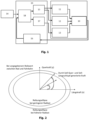
- Fig. 1 is a block diagram of a method for controlling wheel slip of a motor vehicle (not shown).
- the motor vehicle includes a corresponding control unit 19 configured to carry out the method.
- the motor vehicle also has wheel actuators and wheels 10, specifically four wheels 10.
- the wheel actuators include an electromechanical braking system 11, an electric drive system 12, and a steer-by-wire steering system 13.
- the method provides, as a first step, the translation of a target trajectory 14 of the motor vehicle into a target movement of the motor vehicle.
- a target movement generator 18 converts the target trajectory 14 into a two- or three-dimensional target movement of the motor vehicle, specifically of the wheels 10 of the motor vehicle.
- the target trajectory 14 is provided by a human-machine interface, specifically an operating system with a steering wheel, pedals, and/or gearshift lever, and/or a computer-implemented method, specifically software for automated or autonomous driving.
- the human-machine interface and the computing unit on which the computer-implemented method is executed are part of the motor vehicle, i.e., are arranged internally within the vehicle. Both the human-machine interface and the computing unit on which the computer-implemented method is executed can also be arranged externally of the vehicle, for example, in a remote control center.
- the target trajectory 14 can also be provided by other systems or computer-implemented methods.
- the target motion generator 18 determines wheel-specific target longitudinal and target lateral slip values 15 for the wheels 10 based on the target motion using a vehicle and tire model 16.
- the target motion generator 18 thus translates the target motion of the motor vehicle into a separate target longitudinal and target lateral slip value for each wheel, using the vehicle and tire model 16.
- the target longitudinal and target transverse slip values 15 are determined based on the actual longitudinal and actual transverse slip values. Specifically, the target motion generator 18 takes the current actual longitudinal and actual transverse slip values into account when determining the next target longitudinal and target transverse slip values 15. This creates a closed-loop control system.
- the target motion generator 18 also determines a target steering angle 17 for the steer-by-wire steering system 13 based on the target motion. Additionally, the target steering angle 17 can also be determined as a function of the target longitudinal and target lateral slip values 15. It is therefore possible for the target steering angle 17 to be determined in such a way that it supports achieving the target longitudinal and target lateral slip values 15 using the actual longitudinal and actual lateral slip values.
- the last step of the procedure involves adjusting the actual longitudinal and actual lateral slip values of the wheels 10 to the respective target longitudinal and target lateral slip values 15 by the electromechanical braking system 11 and the electric drive system 12 as a function of a steering angle, in particular the target steering angle 17 and/or the actual steering angle, of the steer-by-wire steering system 13.
- the wheels 10 are driven and/or braked by the electromechanical braking system 11 and/or the electric drive system 12 as a function of the steering angle in such a way that a change in the actual longitudinal and actual lateral slip values towards the target longitudinal and target lateral slip values 15 is effected.
- the steer-by-wire steering system 13 adjusts the actual steering angle to the target steering angle 17.
- Fig. 2 shows a visualization of the vehicle and tire model 16 used in the method of Fig. 1 is used.
- the vehicle and tire model 16 maps the relationship between the longitudinal and lateral slip values and the maximum transmissible longitudinal and lateral forces of the wheels 10.
- the vehicle and tire model 16 can determine the force generated by the target longitudinal and lateral slip values 15, i.e., the longitudinal and lateral force acting between the wheel and the road surface, and relate it to the maximum transmissible force.
- the vehicle and tire model 16 can determine the combination of target longitudinal and lateral slip values 15 for each wheel at which the essentially maximum transmissible longitudinal and lateral force, or a longitudinal and lateral force with a reduced, in particular minimal, distance from the adhesion limit, acts.
- the ratio of the longitudinal and transverse slip values to the maximum transferable longitudinal and transverse forces is mapped as a function of wheel loads of the wheels 10, in particular of predicted, static and/or dynamic wheel loads of the wheels 10.
- the ratio of the longitudinal and lateral slip values to the maximum transmittable longitudinal and lateral forces is also mapped as a function of a friction coefficient between the wheels 10 and the road surface, wherein the friction coefficient can be determined in particular based on an estimate.
- the vehicle model can comprise a friction ellipse, in particular a Krempel friction ellipse, i.e. a representation of the transferable, in particular the maximum transferable, longitudinal and transverse forces of a wheel with combined longitudinal and transverse slip of the wheel.
- a friction ellipse in particular a Krempel friction ellipse, i.e. a representation of the transferable, in particular the maximum transferable, longitudinal and transverse forces of a wheel with combined longitudinal and transverse slip of the wheel.
- Fig. 1 and Fig. 2 This example illustrates two driving maneuvers on a slippery road surface, where the objective is to prevent a collision between the motor vehicle and an obstacle toward which the vehicle is moving.
- the driving maneuvers are performed by a human driver using an operating system with at least a steering wheel and a brake pedal.
- the driving maneuvers can also be performed by a machine.
- the driver notices the obstacle and depresses the brake pedal while holding the steering wheel straight, i.e., at a steering angle of essentially 0°.
- the method determines the target longitudinal and target lateral slip values 15 such that deceleration is maximized, taking into account disturbing forces on the wheels 10 and the forward weight shift, i.e., the distribution of the wheel loads to the front wheels 10.
- the driver realizes that the obstacle must be avoided by steering, as the vehicle would not come to a stop in front of it.
- the driver therefore moves the steering wheel so that a steering angle of greater than/less than 0° is established while depressing the brake pedal.
- the method then dynamically selects the target longitudinal and target lateral slip values 15 depending on the respective relationship between the wheel and the vehicle alignment, i.e., depending on the steering angle, such that essentially the maximum available lateral force is transmitted between the wheel and the road surface at each steering angle.
- the vehicle and tire model 16 follows the friction ellipse of each wheel, which represents the maximum transmittable longitudinal and lateral force or adhesion limit, as a function of the steering angle.
- the priority according to the method can be to prevent the motor vehicle from rolling over its longitudinal axis.
- the target longitudinal and target lateral slip values 15 are determined such that the lateral forces between the wheels 10 and the road surface tend to decrease, for example, due to the wheels 10 locking, so that the motor vehicle is more likely to slide than roll over.
- the method shown can also be used to manipulate the understeer or oversteer characteristics of the motor vehicle by controlling the longitudinal and lateral slip values for each wheel, especially for driving modes such as sport, off-road and/or comfort.
Landscapes
- Engineering & Computer Science (AREA)
- Transportation (AREA)
- Mechanical Engineering (AREA)
- Automation & Control Theory (AREA)
- Chemical & Material Sciences (AREA)
- Combustion & Propulsion (AREA)
- Human Computer Interaction (AREA)
- Microelectronics & Electronic Packaging (AREA)
- Physics & Mathematics (AREA)
- Fluid Mechanics (AREA)
- Steering Control In Accordance With Driving Conditions (AREA)
- Regulating Braking Force (AREA)
Abstract
- Übersetzen einer Soll-Trajektorie (14) des Kraftfahrzeugs in eine Soll-Bewegung des Kraftfahrzeugs;
- Bestimmen von radindividuellen Soll-Längs- und Soll-Querschlupfwerten (15) für die Räder (10) basierend auf der Soll-Bewegung unter Verwendung eines Fahrzeug- und Reifenmodells (16); und
- Angleichen von Ist-Längs- und Ist-Querschlupfwerten der Räder (10) an die jeweiligen Soll-Längs- und Soll-Querschlupfwerte (15) durch das elektromechanische Bremssystem (11) und das elektrische Antriebssystem (12) in Abhängigkeit von einem Lenkwinkel des Steer-by-Wire-Lenksystems (13).
Description
- Die Erfindung betrifft ein Verfahren zur Steuerung des Radschlupfs eines Kraftfahrzeugs, ein Steuergerät und ein Kraftfahrzeug.
- Zur Fortbewegung eines Kraftfahrzeugs werden Längs- und Seitenkräfte zwischen den Rädern bzw. Reifen und der Fahrbahn übertragen. Dabei ist die Fahrstabilität des Kraftfahrzeugs gegeben, solange die maximal übertragbaren Längs- und Querkräfte, d. h. das verfügbare Kraftpotential bzw. die Haftgrenze, der Räder nicht überschritten werden.
- Die maximal übertragbare Längs- und Querkraft eines Rades hängen im Besonderen vom Radschlupf, von der Radlast sowie vom Reibwert zwischen dem Rad und der Fahrbahn ab. Da die Radlast und der Reibwert nur bedingt steuerbar sind, ist der Radschlupf die wesentliche Stellgröße, um die Fahrstabilität eines Kraftfahrzeugs aktiv sicherzustellen.
- Die Steuerung des Radschlupfs erfolgt typischerweise durch Radaktuatoren, die die Räder abbremsen und/oder beschleunigen, um die Ist-Längs- und Ist-Querschlupfwerte der Räder an Soll-Längs- und Soll-Querschlupfwerte anzugleichen. Dabei ist bekannt, die Soll-Längs- und Soll-Querschlupfwerte auf Basis einer Soll-Trajektorie zu ermitteln, die von einer Mensch-Maschine-Schnittstelle, beispielsweise einem Bediensystem mit Lenkrad, Pedalen und/oder Schalthebel, oder einer Software für automatisiertes und/oder autonomes Fahren bereitgestellt wird.
- Die Steuerung des Radschlupfs ist mit der Überwindung von Trägheiten verbunden und mit Modell- bzw. Schätzfehlern behaftet. Um die Fahrstabilität des Kraftfahrzeugs in jeder Situation sicherzustellen, erfolgt die Steuerung daher üblicherweise mit einem Sicherheitsabstand zur Haftgrenze, also so, dass das verfügbare Kraftpotential der Räder nur bis zu einem gewissen Grad ausgenutzt wird. Dies kann allerdings, insbesondere in Extremsituationen, zu Abweichungen von der Soll-Trajektorie führen und auf diese Weise die Fahrsicherheit einschränken.
- Der Erfindung liegt daher die Aufgabe zu Grunde, ein Verfahren anzugeben, das eine Steuerung des Radschlupfs eines Kraftfahrzeugs mit reduziertem Sicherheitsabstand zur Haftgrenze der Räder ermöglicht. Der Erfindung liegt ferner die Aufgabe zu Grunde, ein entsprechendes Steuergerät sowie ein Kraftfahrzeug anzugeben.
- Erfindungsgemäß wird die Aufgabe mit Blick auf das Verfahren durch den Gegenstand des Anspruchs 1, mit Blick auf das Steuergerät durch den Gegenstand des Anspruchs 7 und mit Blick auf das Kraftfahrzeug durch den Gegenstand des Anspruchs 8 gelöst.
- Konkret wird die Aufgabe durch ein Verfahren zur Steuerung des Radschlupfs eines Kraftfahrzeugs, das wenigstens zwei Räder, ein elektromechanisches Bremssystem, ein elektrisches Antriebssystem und ein Steer-by-Wire-Lenksystem aufweist, gelöst. Das Verfahren umfasst folgende Schritte:
- Übersetzen einer Soll-Trajektorie des Kraftfahrzeugs in eine Soll-Bewegung des Kraftfahrzeugs;
- Bestimmen von radindividuellen Soll-Längs- und Soll-Querschlupfwerten für die Räder basierend auf der Soll-Bewegung unter Verwendung eines Fahrzeug- und Reifenmodells; und
- Angleichen von Ist-Längs- und Ist-Querschlupfwerten der Räder an die jeweiligen Soll-Längs- und Soll-Querschlupfwerte durch das elektromechanische Bremssystem und das elektrische Antriebssystem in Abhängigkeit von einem Lenkwinkel des Steer-by-Wire-Lenksystems.
- Das erfindungsgemäße Verfahren beruht zum einen auf dem Gedanken, die Soll-Trajektorie in einem Zwischenschritt in eine Soll-Bewegung des Kraftfahrzeugs zu übersetzen. Dadurch können die Soll-Längs- und Soll-Querschlupfwerte mittels eines Fahrzeug- und Reifenmodells so bestimmt werden, dass sie die Soll-Bewegung besonders präzise abbilden. Auf diese Weise werden Modell- bzw. Schätzfehler bei der Ermittlung der Soll-Längs- und Soll-Querschlupfwerte reduziert, sodass nur ein geringer Sicherheitsabstand zur Haftgrenze der Räder eingehalten werden muss.
- Zum anderen ist vorteilhafterweise vorgesehen, zum Angleichen der Ist-Längs- und Ist-Querschlupfwerte an die Soll-Längs- und Soll-Querschlupfwerte ein elektromechanisches Bremssystem und ein elektrisches Antriebssystem zu verwenden. Diese Systeme ermöglichen aufgrund ihrer reduzierten Trägheiten ein besonders schnelles Angleichen der Ist-Längs- und Ist-Querschlupfwerte an die Soll-Längs- und Soll-Querschlupfwerte, sodass der erforderliche Sicherheitsabstand zur Haftgrenze vorteilhafterweise weiter reduziert ist.
- Die im Zusammenhang mit dem Verfahren genannten Vorteile gelten in entsprechender Weise auch für das erfindungsgemäße Steuergerät. Die im Zusammenhang mit dem Verfahren beschriebenen Verfahrensschritte sind auch im Zusammenhang mit dem Steuergerät offenbart und zwar in der Form, dass das Steuergerät dazu konfiguriert bzw. angepasst ist, diese Verfahrensschritte durchzuführen.
- Unter einer Trajektorie wird insbesondere die zeitliche Entwicklung der Position des Kraftfahrzeugs, also insbesondere die Kombination aus der Route bzw. dem Fahrweg und dem Geschwindigkeitsprofil entlang der Route, verstanden. Unter dem Längs- bzw. Querschlupf eines Rades wird insbesondere das Verhältnis der Längs bzw. der Quergeschwindigkeit am Radaußenumfang zur Längs bzw. Quergeschwindigkeit am Radmittelpunkt verstanden. Unter der Radlast wird insbesondere die Kraft verstanden, die senkrecht zur Fahrbahn von ihr auf das Rad wirkt.
- Die Begriffe Rad und Reifen werden vorliegend synonym verwendet. Der Begriff Steuerung wird hier nicht im regelungstechnisch strengen Sinn verstanden, sondern umfasst auch eine Regelung (closed control). Die Erfindung betrifft somit insbesondere auch ein Verfahren zur Regelung eines des Radschlupfs sowie ein entsprechendes Steuergerät und Kraftfahrzeug.
- Bevorzugte Ausführungsformen der Erfindung sind in den Unteransprüchen angegeben.
- In einer vorteilhaften Ausführungsform der Erfindung werden die Soll-Längs- und Soll-Querschlupfwerte basierend auf den Ist-Längs- und Ist-Querschlupfwerten bestimmt. Vorteilhafterweise fließen also die Ist-Längs- und Ist-Querschlupfwerte in die Bestimmung der nächsten Soll-Längs- und Soll-Querschlupfwerte mit ein. Mit einer solchen dynamischen Steuerung des Radschlupfs, insbesondere einer Closed-Loop-Steuerung, kann vorteilhafterweise auf Abweichungen von der Soll-Bewegung, beispielsweise aufgrund von Störungen in der Realität, schneller reagiert werden, sodass der Sicherheitsabstand zur Haftgrenze der Räder vorteilhafterweise weiter reduziert werden kann.
- In einer weiteren vorteilhaften Ausführungsform der Erfindung bildet das Fahrzeug- und Reifenmodell das Verhältnis von Längs- und Querschlupfwerten der Räder zu maximal übertragbaren Längs- und Querkräften der Räder ab. Durch die Berücksichtigung der maximal übertragbaren Längs- und Querkräfte beim Bestimmen der Soll-Längs- und Soll-Querschlupfwerte kann das verfügbare Reifenkraftpotential vorteilhafterweise besser ausgenutzt werden.
- Für ein besonders präzises Bestimmen der Soll-Längs- und Soll-Querschlupfwerte ist es vorteilhaft, wenn das Fahrzeug- und Reifenmodell das Verhältnis der Längs- und Querschlupfwerte zu den maximal übertragbaren Längs- und Querkräften in Abhängigkeit von Radlasten der Räder abbildet, insbesondere in Abhängigkeit von prognostizierten, statischen und/oder dynamischen Radlasten der Räder.
- Um die Soll-Längs- und Soll-Querschlupfwerte noch präziser zu bestimmen, wird das Verhältnis der Längs- und Querschlupfwerten zu den maximal übertragbaren Längs- und Querkräften vorteilhafterweise in Abhängigkeit von einem Reibwert, insbesondere einem geschätzten Reibwert, zwischen den Rädern und der Fahrbahn abgebildet.
- Vorzugsweise wird die Soll-Trajektorie von einer Mensch-Maschine-Schnittstelle und/oder einem computerimplementierten Verfahren, beispielsweise für automatisiertes oder autonomes Fahren, bereitgestellt. Dies hat den Vorteil, dass die Erfindung mit bekannten Schnittstellen im Kraftfahrzeug kompatibel und/oder auf Standardsysteme anwendbar ist.
- Die Erfindung wird nachstehend anhand eines Ausführungsbeispiels unter Bezug auf die beigefügten schematischen Figuren mit weiteren Einzelheiten näher erläutert.
- Dabei zeigen
- Fig. 1
- ein Blockschaltbild eines erfindungsgemäßen Ausführungsbeispiels eines Verfahrens zur Steuerung des Radschlupfs eines Kraftfahrzeugs; und
- Fig. 2
- eine Visualisierung des Fahrzeug- und Reifenmodells, das in dem Verfahren aus
Fig. 1 verwendet wird. - In
Fig. 1 ist ein Blockschaltbild eines Verfahrens zur Steuerung des Radschlupfs eines Kraftfahrzeugs (nicht gezeigt). - Das Kraftfahrzeug umfasst ein entsprechendes Steuergerät 19, das zur Durchführung des Verfahrens konfiguriert ist. Das Kraftfahrzeug weist darüber hinaus Radaktuatoren und Räder 10, konkret vier Räder 10, auf. Die Radaktuatoren umfassen ein elektromechanisches Bremssystem 11, ein elektrisches Antriebssystem 12 und ein Steer-by-Wire-Lenksystem 13.
- Das Verfahren sieht als ersten Schritt vor, eine Soll-Trajektorie 14 des Kraftfahrzeugs in eine Soll-Bewegung des Kraftfahrzeugs zu übersetzen. Dazu rechnet ein Soll-Bewegungsgenerator 18 die Soll-Trajektorie 14 in eine zwei- oder dreidimensionale Soll-Bewegung des Kraftfahrzeugs, konkret der Räder 10 des Kraftfahrzeugs, um.
- Die Soll-Trajektorie 14 wird von einer Mensch-Maschine-Schnittstelle, konkret einem Bediensystem mit Lenkrad, Pedalen und/oder Schalthebel, und/oder einem computerimplementierten Verfahren, konkret einer Software für automatisiertes oder autonomes Fahren, bereitgestellt wird. Im gezeigten Ausführungsbeispiel sind die Mensch-Maschine-Schnittstelle und die Recheneinheit, auf der das computerimplementierte Verfahren ausgeführt wird, Teil des Kraftfahrzeugs, also fahrzeugintern angeordnet. Sowohl die Mensch-Maschine-Schnittstelle als auch die Recheneinheit, auf der das computerimplementierte Verfahren ausgeführt wird, können auch fahrzeugextern, beispielsweise in einer entfernten Zentrale, angeordnet sein. Die Soll-Trajektorie 14 kann auch von anderen Systemen oder computerimplementierten Verfahren bereitgestellt werden.
- Gemäß dem nächsten Schritt des Verfahrens bestimmt der Soll-Bewegungsgenerator 18 radindividuelle Soll-Längs- und Soll-Querschlupfwerte 15 für die Räder 10 basierend auf der Soll-Bewegung unter Verwendung eines Fahrzeug- und Reifenmodells 16. Der Soll-Bewegungsgenerator 18 übersetzt also die Soll-Bewegung des Kraftfahrzeugs in jeweils einen eigenen Soll-Längs- und Soll-Querschlupfwert pro Rad, wobei er auf das Fahrzeug- und Reifenmodell 16 zurückgreift.
- Die Soll-Längs- und Soll-Querschlupfwerte 15 werden dabei basierend auf den Ist-Längs- und Ist-Querschlupfwerten bestimmt. Konkret berücksichtigt der Soll-Bewegungsgenerator 18 die aktuellen Ist-Längs- und Ist-Querschlupfwerte beim Bestimmen der nächsten Soll-Längs- und Soll-Querschlupfwerte 15. Dadurch wird ein geschlossener Steuerkreis bzw. eine Closed-Loop-Steuerung gebildet.
- Der Soll-Bewegungsgenerator 18 bestimmt darüber hinaus einen Soll-Lenkwinkel 17 für das Steer-by-Wire-Lenksystem 13 basierend auf der Soll-Bewegung. Zusätzlich kann der Soll-Lenkwinkel 17 auch in Abhängigkeit der Soll-Längs- und Soll-Querschlupfwerte 15 bestimmt werden. Es ist also möglich, dass der Soll-Lenkwinkel 17 derart bestimmt wird, dass er ein Erreichen der Soll-Längs- und Soll-Querschlupfwerte 15 durch die Ist-Längs- und Ist-Querschlupfwerte unterstützt.
- Der letzte Schritt des Verfahrens sieht ein Angleichen der Ist-Längs- und Ist-Querschlupfwerte der Räder 10 an die jeweiligen Soll-Längs- und Soll-Querschlupfwerte 15 durch das elektromechanische Bremssystem 11 und das elektrische Antriebssystem 12 in Abhängigkeit von einem Lenkwinkel, insbesondere Soll-Lenkwinkel 17 und/oder Ist-Lenkwinkel, des Steer-by-Wire-Lenksystems 13 vor. Hierzu werden die Räder 10 in Abhängigkeit vom Lenkwinkel derart durch das elektromechanische Bremssystem 11 und/oder das elektrische Antriebssystem 12 angetrieben und/oder abgebremst, dass eine Änderung der Ist-Längs- und Ist-Querschlupfwerte in Richtung Soll-Längs- und Soll-Querschlupfwerte 15 bewirkt wird.
- Das Steer-by-Wire-Lenksystem 13 gleicht den Ist-Lenkwinkel an den Soll-Lenkwinkel 17 an.
-
Fig. 2 zeigt eine Visualisierung des Fahrzeug- und Reifenmodells 16, das in dem Verfahren ausFig. 1 verwendet wird. - Das Fahrzeug- und Reifenmodell 16 bildet das Verhältnis der Längs- und Querschlupfwerte zu den maximal übertragbaren Längs- und Querkräften der Räder 10 ab. So kann das Fahrzeug- und Reifenmodell 16 die durch die Soll-Längs- und Soll-Querschlupfwerte 15 generierte Kraft, d. h. Längs- und Querkraft, die zwischen dem Rad und der Fahrbahn wirkt, bestimmen und in Beziehung zur maximal übertragebaren Kraft setzen. Ebenso kann das Fahrzeug- und Reifenmodell 16 die Kombination aus Soll-Längs- und Soll-Querschlupfwerten 15 jedes Rades bestimmen, bei der die im Wesentlichen maximal übertragebare Längs- und Querkraft bzw. eine Längs- und Querkraft mit reduziertem, insbesondere minimalen, Abstand zur Haftgrenze wirkt.
- Dabei wird das Verhältnis von den Längs- und Querschlupfwerten zu den maximal übertragbaren Längs- und Querkräften in Abhängigkeit von Radlasten der Räder 10 abgebildet, insbesondere von prognostizierten, statischen und/oder dynamischen Radlasten der Räder 10 abgebildet.
- Das Verhältnis von den Längs- und Querschlupfwerten zu den maximal übertragbaren Längs- und Querkräften wird außerdem in Abhängigkeit von einem Reibwert zwischen den Rädern 10 und der Fahrbahn abgebildet, wobei der Reibwert insbesondere basierend auf einer Schätzung bestimmt werden kann.
- Das Fahrzeugmodell kann eine Reibungsellipse, insbesondere eine Krempelsche Reibungsellipse umfassen, also eine Darstellung der übertragbaren, insbesondere der maximal übertragbaren, Längs- und Querkräfte eines Rades bei kombiniertem Längs- und Querschlupf des Rades.
- Nachstehend wird das Verfahren aus
Fig. 1 und Fig. 2 anhand von zwei beispielhaften Fahrmanövern auf einer glatten Fahrbahn erläutert, wobei ein Zusammenstoß des Kraftfahrzeugs mit einem Hindernis, auf das sich das Kraftfahrzeug zubewegt, verhindert werden soll. Die Fahrmanöver werden von einem menschlichen Fahrer durch ein Bediensystem mit wenigstens einem Lenkrad und einem Bremspedal ausgeführt. Die Fahrmanöver können auch von einer Maschine ausgeführt werden. - In einem ersten Fahrmanöver bemerkt der Fahrer das Hindernis und betätigt das Bremspedal, während der Fahrer das Lenkrad gerade, also bei einem Lenkwinkel von im Wesentlichen 0°, hält. Daraufhin werden gemäß dem Verfahren die Soll-Längs- und Soll-Querschlupfwerte 15 derart bestimmt, dass die Verzögerung unter Berücksichtigung von Störkräften auf die Räder 10 und der Gewichtsverlagerung nach vorne, d. h. der Verteilung der Radlasten auf die vorderen Räder 10, maximiert wird.
- In einem zweiten Fahrmanöver bemerkt der Fahrer, dass das Hindernis durch ein Lenkmanöver umfahren werden muss, da das Kraftfahrzeug vor dem Hindernis nicht zum Stehen kommen würde. Also bewegt der Fahrer das Lenkrad, sodass sich ein Lenkwinkel von größer/kleiner 0° einstellt, während er das Bremspedal betätigt. Daraufhin werden gemäß dem Verfahren die Soll-Längs- und Soll-Querschlupfwerte 15 dynamisch in Abhängigkeit vom jeweiligen Verhältnis zwischen dem Rad und der Fahrzeugausrichtung, also in Abhängigkeit vom Lenkwinkel, derart gewählt, dass zwischen dem Rad und der Fahrbahn bei jedem Lenkwinkel die im Wesentlichen maximal verfügbare Querkraft übertragen wird. Dazu folgt das Fahrzeug- und Reifenmodell 16 der Reibungsellipse jedes Rades, die die maximal übertragebare Längs- und Querkraft bzw. Haftgrenze repräsentiert, in Abhängigkeit des Lenkwinkels.
- Wird während eines hochdynamischen Fahrmanövers die Radlast auf einer Seite des Kraftfahrzeugs besonders gering, so kann gemäß dem Verfahren die Priorität darin bestehen, ein Überrollen des Kraftfahrzeugs um seine Längsachse zu vermeiden. Dazu werden die Soll-Längs- und Soll-Querschlupfwerte 15 derart bestimmt, dass die Querkräfte zwischen den Rädern 10 und der Fahrbahn, beispielsweise durch ein Blockieren der Räder 10, tendenziell abnehmen, sodass das Kraftfahrzeug eher rutscht als überrollt.
- Das gezeigte Verfahren kann auch dazu verwendet werden, die Unter- bzw. Übersteuerungscharakteristik des Kraftfahrzeugs durch die radindividuelle Steuerung der Längs- und Querschlupfwerte, insbesondere für Fahrmodi wie Sport, Offroad und/oder Komfort, zu manipulieren.
-
- 10
- Räder
- 11
- elektromechanisches Bremssystem
- 12
- elektrisches Antriebssystem
- 13
- Steer-by-Wire-Lenksystem
- 14
- Soll-Trajektorie
- 15
- Soll-Längs- und Soll-Querschlupfwerte
- 16
- Fahrzeug- und Reifenmodell
- 17
- Soll-Lenkwinkel
- 18
- Soll-Bewegungsgenerator
- 19
- Steuergerät
Claims (8)
- Verfahren zur Steuerung des Radschlupfs eines Kraftfahrzeugs, das wenigstens zwei Räder (10), ein elektromechanisches Bremssystem (11), ein elektrisches Antriebssystem (12) und ein Steer-by-Wire-Lenksystem (13) aufweist, wobei das Verfahren folgende Schritte umfasst:- Übersetzen einer Soll-Trajektorie (14) des Kraftfahrzeugs in eine Soll-Bewegung des Kraftfahrzeugs;- Bestimmen von radindividuellen Soll-Längs- und Soll-Querschlupfwerten (15) für die Räder (10) basierend auf der Soll-Bewegung unter Verwendung eines Fahrzeug- und Reifenmodells (16); und- Angleichen von Ist-Längs- und Ist-Querschlupfwerten der Räder (10) an die jeweiligen Soll-Längs- und Soll-Querschlupfwerte (15) durch das elektromechanische Bremssystem (11) und das elektrische Antriebssystem (12) in Abhängigkeit von einem Lenkwinkel des Steer-by-Wire-Lenksystems (13).
- Verfahren nach Anspruch 1,
dadurch gekennzeichnet, dass die Soll-Längs- und Soll-Querschlupfwerte (15) basierend auf den Ist-Längs- und Ist-Querschlupfwerten bestimmt werden. - Verfahren nach Anspruch 1 oder 2,
dadurch gekennzeichnet, dass das Fahrzeug- und Reifenmodell (16) das Verhältnis von Längs- und Querschlupfwerten der Räder (10) zu maximal übertragbaren Längs- und Querkräften der Räder (10) abbildet. - Verfahren nach Anspruch 3,
dadurch gekennzeichnet, dass das Verhältnis in Abhängigkeit von, insbesondere prognostizierten, statischen und/oder dynamischen Radlasten der Räder (10) abgebildet wird. - Verfahren nach Anspruch 3 oder 4,
dadurch gekennzeichnet, dass das Verhältnis in Abhängigkeit von einem, insbesondere geschätzten, Reibwert zwischen den Rädern (10) und der Fahrbahn abgebildet wird. - Verfahren nach einem der vorhergehenden Ansprüche,
dadurch gekennzeichnet, dass die Soll-Trajektorie (14) von einer Mensch-Maschine-Schnittstelle und/oder einem computerimplementierten Verfahren bereitgestellt wird. - Steuergerät zu Steuerung des Radschlupfs eines Kraftfahrzeugs, das wenigstens zwei Räder (10), ein elektromechanisches Bremssystem (11), ein elektrisches Antriebssystem (12) und ein Steer-by-Wire-Lenksystem (13) aufweist, wobei das Steuergerät zur Durchführung folgender Schritte angepasst ist:- Übersetzen einer Soll-Trajektorie (14) des Kraftfahrzeugs in eine Soll-Bewegung des Kraftfahrzeugs;- Bestimmen von radindividuellen Soll-Längs- und Soll-Querschlupfwerten (15) für die Räder (10) basierend auf der Soll-Bewegung unter Verwendung eines Fahrzeug- und Reifenmodells (16); und- Angleichen von Ist-Längs- und Ist-Querschlupfwerten der Räder (10) an die jeweiligen Soll-Längs- und Soll-Querschlupfwerte (15) durch das elektromechanische Bremssystem (11) und das elektrische Antriebssystem (12) in Abhängigkeit eines Lenkwinkels des Steer-by-Wire-Lenksystems (13).
- Kraftfahrzeug mit einem Steuergerät (19) nach Anspruch 7.
Applications Claiming Priority (1)
| Application Number | Priority Date | Filing Date | Title |
|---|---|---|---|
| BE20235904A BE1032111B1 (de) | 2023-11-02 | 2023-11-02 | Verfahren zur Steuerung des Radschlupfs eines Kraftfahrzeugs, Steuergerät und Kraftfahrzeug |
Publications (2)
| Publication Number | Publication Date |
|---|---|
| EP4549268A1 true EP4549268A1 (de) | 2025-05-07 |
| EP4549268B1 EP4549268B1 (de) | 2026-05-13 |
Family
ID=88689593
Family Applications (1)
| Application Number | Title | Priority Date | Filing Date |
|---|---|---|---|
| EP24208958.9A Active EP4549268B1 (de) | 2023-11-02 | 2024-10-25 | Verfahren zur steuerung des radschlupfs eines kraftfahrzeugs, steuergerät und kraftfahrzeug |
Country Status (3)
| Country | Link |
|---|---|
| US (1) | US20250145147A1 (de) |
| EP (1) | EP4549268B1 (de) |
| BE (1) | BE1032111B1 (de) |
Citations (4)
| Publication number | Priority date | Publication date | Assignee | Title |
|---|---|---|---|---|
| US20200247394A1 (en) * | 2017-09-20 | 2020-08-06 | Hitachi Automotive Systems, Ltd. | Vehicle Control Apparatus, Vehicle Control Method, and Vehicle Control System |
| EP3694766B1 (de) * | 2017-10-10 | 2021-11-24 | Volvo Truck Corporation | Verfahren zur steuerung eines lenksystems eines fahrzeugs |
| US20230311849A1 (en) * | 2020-08-13 | 2023-10-05 | Continental Automotive Technologies GmbH | Motion control in motor vehicles |
| US20230322207A1 (en) * | 2020-08-19 | 2023-10-12 | Zf Cv Systems Global Gmbh | Method for the automated guidance of a vehicle, journey control unit and vehicle |
-
2023
- 2023-11-02 BE BE20235904A patent/BE1032111B1/de active IP Right Grant
-
2024
- 2024-10-25 EP EP24208958.9A patent/EP4549268B1/de active Active
- 2024-10-31 US US18/933,441 patent/US20250145147A1/en active Pending
Patent Citations (4)
| Publication number | Priority date | Publication date | Assignee | Title |
|---|---|---|---|---|
| US20200247394A1 (en) * | 2017-09-20 | 2020-08-06 | Hitachi Automotive Systems, Ltd. | Vehicle Control Apparatus, Vehicle Control Method, and Vehicle Control System |
| EP3694766B1 (de) * | 2017-10-10 | 2021-11-24 | Volvo Truck Corporation | Verfahren zur steuerung eines lenksystems eines fahrzeugs |
| US20230311849A1 (en) * | 2020-08-13 | 2023-10-05 | Continental Automotive Technologies GmbH | Motion control in motor vehicles |
| US20230322207A1 (en) * | 2020-08-19 | 2023-10-12 | Zf Cv Systems Global Gmbh | Method for the automated guidance of a vehicle, journey control unit and vehicle |
Also Published As
| Publication number | Publication date |
|---|---|
| US20250145147A1 (en) | 2025-05-08 |
| BE1032111A1 (de) | 2025-05-28 |
| EP4549268B1 (de) | 2026-05-13 |
| BE1032111B1 (de) | 2025-06-02 |
Similar Documents
| Publication | Publication Date | Title |
|---|---|---|
| EP1459928B1 (de) | Vorrichtung zum Beschleunigen und/oder Verzögern eines Kraftfahrzeugs und Verfahren zur Einstellung der Geschwindigkeit eines Kraftfahrzeugs | |
| DE102013216630B4 (de) | Verfahren und Vorrichtung zur Steuerung eines assistierten Parkvorgangs eines Kraftfahrzeugs | |
| DE10203954B4 (de) | Fahrzeugfahrsteuerungsvorrichtung | |
| EP3057841B1 (de) | Verfahren zum führen eines kraftfahrzeugs und kraftfahrzeug zum ausführen des verfahrens | |
| EP3489112B1 (de) | Verfahren und lenksystem zum lenken eines fahrzeugs | |
| DE102019135087A1 (de) | Verfahren und Vorrichtung zur Schlupfregelung eines Fahrzeugrades | |
| EP3544849B1 (de) | Allradsystem für ein elektrisches kraftfahrzeug und verfahren zum betreiben eines allradsystems eines solchen fahrzeugs | |
| WO2008037347A1 (de) | Bremssystem und verfahren zum bremsen eines fahrzeugs mit einem hybridantrieb | |
| EP2487079B1 (de) | Verfahren zum Betreiben eines Kraftfahrzeugs bei Durchfahren einer Kurve | |
| WO2018036580A1 (de) | Fahrzeug sowie verfahren zum lenken des fahrzeugs | |
| DE102017011802A1 (de) | Verfahren zur Stabilisierung einer Fahrzeugkombination | |
| EP3496970B1 (de) | Verfahren und vorrichtung zum betreiben eines kraftfahrzeugs, kraftfahrzeug | |
| WO2008028821A1 (de) | Vorausschauendes fahren mit acc | |
| DE102021117960B4 (de) | Verfahren zum fahrsituationsabhängigen Reduzieren einer Raddrehmomentüberhöhung | |
| WO2007051717A1 (de) | Verfahren zum betreiben eines bremssystems eines kraftfahrzeugs | |
| DE102022205632A1 (de) | Verfahren zum Erzeugen eines Sollwerts, Verfahren zum Steuern eines Aktuators und Steuerungsvorrichtung | |
| BE1032111B1 (de) | Verfahren zur Steuerung des Radschlupfs eines Kraftfahrzeugs, Steuergerät und Kraftfahrzeug | |
| WO2021197694A1 (de) | Verfahren sowie kraftfahrzeug | |
| DE102013002890A1 (de) | Verfahren und Vorrichtung zur Unterstützung eines Fahrzeugführers eines Kraftfahrzeuges zum Einhalten eines Geschwindigkeitsbereiches | |
| EP3844040A1 (de) | Verfahren zum betreiben eines kraftfahrzeugs sowie entsprechendes kraftfahrzeug | |
| DE102020101977A1 (de) | Verfahren zum Steuern eines Fahrzeugs | |
| DE102017010500A1 (de) | Nutzfahrzeug | |
| EP1462292A2 (de) | Steuersystem zur variablen Drehmomentenverteilung | |
| DE102016202950A1 (de) | Verfahren für einen Geschwindigkeitsregler und Geschwindigkeitsregler | |
| DE102024202107A1 (de) | Verfahren und Vorrichtung zum Betreiben eines Kraftfahrzeugs |
Legal Events
| Date | Code | Title | Description |
|---|---|---|---|
| PUAI | Public reference made under article 153(3) epc to a published international application that has entered the european phase |
Free format text: ORIGINAL CODE: 0009012 |
|
| STAA | Information on the status of an ep patent application or granted ep patent |
Free format text: STATUS: THE APPLICATION HAS BEEN PUBLISHED |
|
| AK | Designated contracting states |
Kind code of ref document: A1 Designated state(s): AL AT BE BG CH CY CZ DE DK EE ES FI FR GB GR HR HU IE IS IT LI LT LU LV MC ME MK MT NL NO PL PT RO RS SE SI SK SM TR |
|
| STAA | Information on the status of an ep patent application or granted ep patent |
Free format text: STATUS: REQUEST FOR EXAMINATION WAS MADE |
|
| 17P | Request for examination filed |
Effective date: 20250515 |
|
| STAA | Information on the status of an ep patent application or granted ep patent |
Free format text: STATUS: EXAMINATION IS IN PROGRESS |
|
| 17Q | First examination report despatched |
Effective date: 20250808 |
|
| GRAJ | Information related to disapproval of communication of intention to grant by the applicant or resumption of examination proceedings by the epo deleted |
Free format text: ORIGINAL CODE: EPIDOSDIGR1 |
|
| GRAP | Despatch of communication of intention to grant a patent |
Free format text: ORIGINAL CODE: EPIDOSNIGR1 |
|
| GRAP | Despatch of communication of intention to grant a patent |
Free format text: ORIGINAL CODE: EPIDOSNIGR1 |
|
| STAA | Information on the status of an ep patent application or granted ep patent |
Free format text: STATUS: GRANT OF PATENT IS INTENDED |
|
| INTG | Intention to grant announced |
Effective date: 20260226 |
|
| GRAS | Grant fee paid |
Free format text: ORIGINAL CODE: EPIDOSNIGR3 |
|
| GRAA | (expected) grant |
Free format text: ORIGINAL CODE: 0009210 |
|
| STAA | Information on the status of an ep patent application or granted ep patent |
Free format text: STATUS: THE PATENT HAS BEEN GRANTED |
|
| AK | Designated contracting states |
Kind code of ref document: B1 Designated state(s): AL AT BE BG CH CY CZ DE DK EE ES FI FR GB GR HR HU IE IS IT LI LT LU LV MC ME MK MT NL NO PL PT RO RS SE SI SK SM TR |
|
| REG | Reference to a national code |
Ref country code: CH Ref legal event code: F10 Free format text: ST27 STATUS EVENT CODE: U-0-0-F10-F00 (AS PROVIDED BY THE NATIONAL OFFICE) Effective date: 20260513 |