EP4549247A1 - Light control device - Google Patents
Light control device Download PDFInfo
- Publication number
- EP4549247A1 EP4549247A1 EP24207229.6A EP24207229A EP4549247A1 EP 4549247 A1 EP4549247 A1 EP 4549247A1 EP 24207229 A EP24207229 A EP 24207229A EP 4549247 A1 EP4549247 A1 EP 4549247A1
- Authority
- EP
- European Patent Office
- Prior art keywords
- light
- rotary operator
- mode
- case
- small light
- Prior art date
- Legal status (The legal status is an assumption and is not a legal conclusion. Google has not performed a legal analysis and makes no representation as to the accuracy of the status listed.)
- Pending
Links
Images


Classifications
-
- B—PERFORMING OPERATIONS; TRANSPORTING
- B60—VEHICLES IN GENERAL
- B60Q—ARRANGEMENT OF SIGNALLING OR LIGHTING DEVICES, THE MOUNTING OR SUPPORTING THEREOF OR CIRCUITS THEREFOR, FOR VEHICLES IN GENERAL
- B60Q1/00—Arrangement of optical signalling or lighting devices, the mounting or supporting thereof or circuits therefor
- B60Q1/0076—Switches therefor
-
- B—PERFORMING OPERATIONS; TRANSPORTING
- B60—VEHICLES IN GENERAL
- B60Q—ARRANGEMENT OF SIGNALLING OR LIGHTING DEVICES, THE MOUNTING OR SUPPORTING THEREOF OR CIRCUITS THEREFOR, FOR VEHICLES IN GENERAL
- B60Q1/00—Arrangement of optical signalling or lighting devices, the mounting or supporting thereof or circuits therefor
- B60Q1/02—Arrangement of optical signalling or lighting devices, the mounting or supporting thereof or circuits therefor the devices being primarily intended to illuminate the way ahead or to illuminate other areas of way or environments
- B60Q1/04—Arrangement of optical signalling or lighting devices, the mounting or supporting thereof or circuits therefor the devices being primarily intended to illuminate the way ahead or to illuminate other areas of way or environments the devices being headlights
- B60Q1/14—Arrangement of optical signalling or lighting devices, the mounting or supporting thereof or circuits therefor the devices being primarily intended to illuminate the way ahead or to illuminate other areas of way or environments the devices being headlights having dimming means
- B60Q1/1446—Arrangement of optical signalling or lighting devices, the mounting or supporting thereof or circuits therefor the devices being primarily intended to illuminate the way ahead or to illuminate other areas of way or environments the devices being headlights having dimming means controlled by mechanically actuated switches
- B60Q1/1453—Hand actuated switches
- B60Q1/1461—Multifunction switches for dimming headlights and controlling additional devices, e.g. for controlling direction indicating lights
- B60Q1/1469—Multifunction switches for dimming headlights and controlling additional devices, e.g. for controlling direction indicating lights controlled by or attached to a single lever, e.g. steering column stalk switches
- B60Q1/1476—Multifunction switches for dimming headlights and controlling additional devices, e.g. for controlling direction indicating lights controlled by or attached to a single lever, e.g. steering column stalk switches comprising switch controlling means located near the free end of the lever, e.g. press buttons, rotatable rings
-
- B—PERFORMING OPERATIONS; TRANSPORTING
- B60—VEHICLES IN GENERAL
- B60Q—ARRANGEMENT OF SIGNALLING OR LIGHTING DEVICES, THE MOUNTING OR SUPPORTING THEREOF OR CIRCUITS THEREFOR, FOR VEHICLES IN GENERAL
- B60Q2300/00—Indexing codes for automatically adjustable headlamps or automatically dimmable headlamps
- B60Q2300/10—Indexing codes relating to particular vehicle conditions
- B60Q2300/11—Linear movements of the vehicle
- B60Q2300/112—Vehicle speed
-
- B—PERFORMING OPERATIONS; TRANSPORTING
- B60—VEHICLES IN GENERAL
- B60Q—ARRANGEMENT OF SIGNALLING OR LIGHTING DEVICES, THE MOUNTING OR SUPPORTING THEREOF OR CIRCUITS THEREFOR, FOR VEHICLES IN GENERAL
- B60Q2300/00—Indexing codes for automatically adjustable headlamps or automatically dimmable headlamps
- B60Q2300/10—Indexing codes relating to particular vehicle conditions
- B60Q2300/11—Linear movements of the vehicle
- B60Q2300/116—Vehicle at a stop
-
- B—PERFORMING OPERATIONS; TRANSPORTING
- B60—VEHICLES IN GENERAL
- B60Q—ARRANGEMENT OF SIGNALLING OR LIGHTING DEVICES, THE MOUNTING OR SUPPORTING THEREOF OR CIRCUITS THEREFOR, FOR VEHICLES IN GENERAL
- B60Q2300/00—Indexing codes for automatically adjustable headlamps or automatically dimmable headlamps
- B60Q2300/30—Indexing codes relating to the vehicle environment
- B60Q2300/31—Atmospheric conditions
- B60Q2300/314—Ambient light
Definitions
- the present disclosure relates to a light control device.
- JP-A Japanese Patent Application Laid-Open
- JP-A No. 2020-062929 discloses a lever switch including a momentary mechanism that automatically returns a rotary operator provided at a distal end portion of a lever main body to an automatic light position when there is no longer a rotation operation force at a position between the automatic light position and a light OFF position.
- JP-A Japanese Patent Application Laid-Open
- 2020-062929 also discloses transitioning from a lights-completely-on state to a vehicle width light state, and further transitioning from a vehicle width light state to a lights-completely-off state, in a case in which the duration of an OFF operation that causes the rotary operator to be held at the light OFF position is longer than or equal to a predetermined time period.
- the present disclosure provides a light control device capable of suppressing occurrence of an operation error.
- a light control device includes: a rotary operator that is rotatable at least between an automatic light position for instructing to switch to an automatic light mode and a small light position for instructing to switch to a small light lighting mode in which a small light is turned on; a lever main body portion at which a light switch is incorporated, the lever main body having a distal end at which the rotary operator is provided, and the light switch being provided with a momentary mechanism that automatically returns the rotary operator to the automatic light position when there is no longer a rotation operation force on the rotary operator at a position between the automatic light position and the small light position; and a light control section that, in a case in which the rotary operator is at the small light position for a first period of time, deactivates the automatic light mode and switches to the small light lighting mode, and that, in a case in which the rotary operator is at the small light position for a second period of time, which is longer that the first period of time, deactivates the automatic light mode and switches to a light
- the light control section performs control so as to deactivate the automatic light mode and switch to the small light lighting mode in a case in which the rotary operator is at the small light position for a first period of time, and to deactivate the automatic light mode and switch to the light off mode in which lights are completely turned off in a case in which the rotary operator is at the small light position for a second period of time that is longer than the first period of time. For this reason, there is a possibility that an operation error may arise during a period of time until, for example, the procedure of an operation is acquired.
- the rotary operator in accordance with a peripheral environment and a state of a vehicle, one of the following is performed: (1) causing display of, at the display device, the operation condition for switching to the small light lighting mode and the operation condition for switching to the light off mode, (2) causing display of, at the display device, the operation condition for switching to the small light lighting mode, or (3) not causing display of an operation condition at the display device.
- This enables the user to recognize the operation condition by visually checking the operation condition that is displayed at the display device, enabling the occurrence of an operation error to be suppressed even until the user learns the procedure of an operation.
- the above-described (1) to (3) are selected in accordance with the peripheral environment and the state of the vehicle. This enables (2) to be selected in a case in which, for example, the peripheral environment and the state of the vehicle are conditions under which although switching to the small light lighting mode may be instructed, switching to the light off mode is not instructed. Further, in a case in which the peripheral environment and the state of the vehicle are conditions under which neither switching to the small light lighting mode nor switching to the light off mode is instructed, (3) can be selected. This enables the display at the display device to be suppressed from becoming complicated.
- a second aspect is the first aspect, wherein, in a case in which the rotary operator is held at the small light position and a peripheral luminance exceeds a predetermined value, or in a case in which the rotary operator is held at the small light position, the peripheral luminance is less than or equal to the predetermined value, and a drive system of the vehicle is suspended or a shift position is in parking or a parking brake is in operation, the light control section performs processing to (1) cause display of, at the display device, the operation condition for switching to the small light lighting mode and the operation condition for switching to the light off mode.
- the condition "in a case in which a peripheral luminance exceeds a predetermined value” and the condition "the peripheral luminance is less than or equal to the predetermined value, and a drive system of the vehicle is suspended or a shift position is in parking or a parking brake is in operation” in the second aspect are conditions under which switching to the small light lighting mode or switching to the light off mode may be instructed. In this case, selecting the above-described (1) enables appropriate display at the display device.
- a third aspect is the first aspect, wherein, in a case in which the rotary operator is held at the small light position, a peripheral luminance is less than or equal to a predetermined value, a shift position is not in parking, and a parking brake is not in operation, the light control section performs processing to (2) cause display of, at the display device, the operation condition for switching to the small light lighting mode.
- the condition in the third aspect that "a peripheral luminance is less than or equal to a predetermined value, a shift position is not in parking, and a parking brake is not in operation" is a condition under which although switching to the small light lighting mode may be instructed, switching to the light off mode is not instructed. In this case, selecting the above-described (2) enables appropriate display at the display device.
- a fourth aspect is the first aspect, wherein, in a case in which the rotary operator is held at the small light position, a peripheral luminance is less than or equal to a predetermined value, and a vehicle speed is greater than or equal to a predetermined vehicle speed, the light control section does (3) not cause display of an operation condition at the display device.
- the condition in the fourth aspect that "a peripheral luminance is less than or equal to a predetermined value, and a vehicle speed is greater than or equal to a predetermined vehicle speed" is a condition under which neither switching to the small light lighting mode nor switching to the light off mode is instructed. In this case, selecting the above-described (3) enables appropriate display at the display device.
- occurrence of an operation error can be suppressed.
- An onboard system 10 illustrated in Fig. 1 is installed at a vehicle, and includes a vehicle speed determination electronic control unit (ECU) 12, a shift position determination ECU 14, a parking brake ECU 16, a surrounding environment determination ECU 18, a display device 20, and a light control ECU 22.
- the vehicle speed determination ECU 12, the shift position determination ECU 14, the parking brake ECU 16, the surrounding environment determination ECU 18, the display device 20, and the light control ECU 22 are connected via a communication line (for example, a controller area network (CAN) bus).
- a communication line for example, a controller area network (CAN) bus
- the above-described ECUs respectively include a central processing unit (CPU), memory such as read only memory (ROM), or random access memory (RAM), and a non-volatile storage section such as a hard disk drive (HDD) or a solid state drive (SSD).
- CPU central processing unit
- ROM read only memory
- RAM random access memory
- non-volatile storage section such as a hard disk drive (HDD) or a solid state drive (SSD).
- HDD hard disk drive
- SSD solid state drive
- the vehicle speed determination ECU 12 acquires a detection signal from a vehicle speed sensor, which is not illustrated in the drawings, and determines a vehicle speed of the vehicle based on the acquired detection signal.
- the shift position determination ECU 14 acquires a detection signal from a shift position sensor, which is not illustrated in the drawings, and determines a shift position of the vehicle based on the acquired detection signal.
- the parking brake ECU 16 acquires a detection signal from a parking brake sensor, which is not illustrated in the drawings, and determines an operating state (in operation/not in operation) of a parking brake of the vehicle based on the acquired detection signal.
- the surrounding environment determination ECU 18 acquires a detection signal from a sensor, which is not illustrated in the drawings, that detects the luminance around the vehicle, and based on the acquired detection signal, determines the luminance around the vehicle as the surrounding environment of the vehicle.
- a luminance sensor that is provided at the vehicle in order to perform automatic-light control in which a headlight of the vehicle is turned on and off in accordance with the luminance around the vehicle, or a camera that is provided at the vehicle to image the surroundings of the vehicle, can be applied.
- the surrounding environment determination ECU 18 may be configured to estimate the luminance around the vehicle by acquiring weather information from an external weather information server or the like, and determining day and night from the acquired weather information and/or determining the weather to be fine weather, cloudy weather or the like. Further, the surrounding environment determination ECU 18 may be configured to estimate the luminance around the vehicle by acquiring a current position of the vehicle from, for example, a global navigation satellite system (GNSS) device, and determining whether or not the vehicle is traveling through a tunnel.
- GNSS global navigation satellite system
- the display device 20 is a display that enables the light control ECU 22 to display an operation method of an operation lever 32 for deactivating an automatic light mode.
- a meter display provided at an instrument panel of the vehicle can be applied.
- a light switch 34 which is incorporated at the operation lever 32, is connected to the light control ECU 22 via a communication line such as a CAN bus, and a headlight device 26 is also connected to the light control ECU 22.
- the headlight device 26 is provided with a headlight 28 and a small light (also referred to as a position light) 30.
- the operation lever 32 includes a lever main body 36 and a rotary operator 38.
- the lever main body 36 is a rod-shaped member, and is supported at a side portion of a steering column of the vehicle such that the lever main body 36 is able to operate to tilt in a vehicle front-rear direction and a vehicle vertical direction.
- the light control ECU 22 switches the optical axis of the headlight 28 or turns on or off a turn signal lamp in accordance with a direction in which the lever main body 36 is tilted.
- the light switch 34 is incorporated at the lever main body 36 (see Fig. 1 ).
- the rotary operator 38 is provided at a distal end portion of the lever main body 36 so as to be rotatable around the axis of the lever main body 36.
- a light ON position (HEAD) 40 for instructing constant lighting of the headlight 28 and the small light
- an automatic light position (AUTO) 42 for setting an automatic light mode in which the turning on and off of the headlight 28 and the small light 30 is controlled based on the luminance around the vehicle
- a small light position 44 for instructing to switch to a small light lighting mode in which the small light 30 is turned on are provided in this order along the rotation direction of the rotary operator 38.
- the contact points of the light switch 34 are switched by a user, who is an occupant of the vehicle, rotating the rotary operator 38.
- the light switch 34 then outputs, to the light control ECU 22, switch contact information that indicates which one of the light ON position 40, the automatic light position 42, or the small light position 44 the rotary operator 38 is positioned at.
- the rotary operator 38 In a case in which the rotary operator 38 is positioned at the light ON position 40, the rotary operator 38 is held at the light ON position 40 even if there is no longer an operation force of a rotation operation by the user. Moreover, in a case in which the rotary operator 38 is positioned at the automatic light position 42, the rotary operator 38 is held at the automatic light position 42 even if there is no longer the operation force of the rotation operation by the user.
- the light switch 34 is provided with a momentary mechanism that, in a case in which the rotary operator 38 is positioned between the automatic light position 42 and the small light position 44, automatically returns the rotary operator 38 to the automatic light position 42 when there is no longer the operation force of the rotation operation by the user.
- the momentary mechanism can be implemented by, for example, using a spring mechanism, which is not illustrated in the drawings, to continuously apply a rotation urging force to the rotary operator 38 at the small light position 44 toward an automatic light position 42 side to an extent that enables the user to perform a rotation operation.
- the storage section of the light control ECU 22 stores a light control program that is not illustrated in the drawings.
- the light control ECU 22 functions as the light control section 24 illustrated in Fig. 1 by reading the light control program from the storage section and loading the light control program in the memory, and the light control program that has been loaded in the memory being executed by the CPU.
- the light control section 24 Based on the switch contact information that is input from the light switch 34, in a case in which the rotary operator 38 is positioned at the light ON position 40, the light control section 24 turns on all of the headlights 28 and the small lights 30 regardless of the luminance around the vehicle (day or night). Moreover, in a case in which the rotary operator 38 is positioned at the automatic light position 42, if the luminance around the vehicle exceeds a predetermined value (during daytime or the like), the light control section 24 turns off all of the headlights 28 and the small lights 30, and if the luminance around the vehicle is less than or equal to a predetermined value, the light control section 24 turns on all of the headlights 28 and the small lights 30.
- the light control section 24 performs the light control processing described below.
- the operation lever 32 which includes the lever main body 36 and the rotary operator 38, and the light control ECU 22, which functions as the light control section 24, are examples of a light control device according to the present disclosure.
- the light control section 24 determines whether or not the rotary operator 38 is held at the small light position 44 against the rotation urging force of the momentary mechanism. In a case in which the determination at step 60 is negative, the light control processing is ended. On the other hand, after the rotary operator 38 has been rotated to the small light position 44 against the rotation urging force of the momentary mechanism as illustrated by the arrow A in Fig. 4A , in a case in which the rotary operator 38 is held at the small light position 44 as illustrated in Fig. 4B , the determination at step 60 is affirmative, and the processing transitions to step 62. At step 62, the light control section 24 starts timing a period of time (a holding time period) during which the rotary operator 38 is held at the small light position 44.
- a period of time a holding time period
- the light control section 24 acquires the peripheral environment of the vehicle and the state of the vehicle. Namely, as the peripheral environment of the vehicle, the light control section 24 acquires the luminance around the vehicle from the surrounding environment determination ECU 18. Further, the light control section 24 acquires, as the state of the vehicle, the vehicle speed of the vehicle from the vehicle speed determination ECU 12, acquires the shift position of the vehicle from the shift position determination ECU 14, and acquires the operating state of the parking brake of the vehicle from the parking brake ECU 16. Moreover, the light control section 24 acquires a state of an ignition switch of the vehicle as the state of the vehicle. In a case in which the acquired state of the ignition switch of the vehicle is "OFF", the light control section 24 determines that the drive system of the vehicle is suspended.
- the light control section 24 determines whether or not the peripheral luminance of the vehicle acquired at step 64 exceeds a predetermined value.
- the predetermined value at step 66 is set to a value for determining whether or not the peripheral environment is daytime or nighttime. Accordingly, at step 66, it is determined whether or not the surroundings of the vehicle are daytime. In a case in which the determination at step 66 is affirmative, the processing transitions to step 70, while in a case in which the determination at step 66 is negative, the processing transitions to step 68.
- the light control section 24 branches the processing based on the peripheral environment of the vehicle and the state of the vehicle acquired at step 64. More specifically, in a case in which the peripheral luminance of the vehicle is less than or equal to a predetermined value, and the drive system of the vehicle is suspended or the shift position is in parking or the parking brake is in operation (hereinafter referred to as "condition A"), the processing transitions to step 70. Further, in a case in which the peripheral luminance of the vehicle is less than or equal to the predetermined value and the shift position is not in parking and the parking brake is not in operation (hereinafter referred to as "condition B"), the processing transitions to step 74.
- condition A the peripheral luminance of the vehicle is less than or equal to a predetermined value, and the drive system of the vehicle is suspended or the shift position is in parking or the parking brake is in operation
- condition B the processing transitions to step 74.
- condition C a predetermined vehicle speed
- the light control section 24 causes display of, at the display device 20, an operation method of deactivating the automatic light mode and turning on the small light 30, and an operation method of deactivating the automatic light mode and completely turning off the lights.
- an operation method of deactivating the automatic light mode and turning on the small light 30 is an operation method of holding the rotary operator 38 at the small light position 44 for one second (or longer).
- an operation method of deactivating the automatic light mode and completely turning off the lights is an operation method of holding the rotary operator 38 at the small light position 44 for two seconds (or longer).
- the light control section 24 causes display of, at the display device 20, an operation method of deactivating the automatic light mode and turning on the small light 30.
- an operation method of deactivating the automatic light mode and turning on the small light 30 is an operation method of holding the rotary operator 38 at the small light position 44 for one second (or longer).
- the light control section 24 does not cause display of an operation method at the display device 20.
- the light control section 24 sets the processing number to "3" at the next step 80, and the processing transitions to step 82.
- step 82 the light control section 24 determines whether or not the operation of holding the rotary operator 38 at the small light position 44 has ended. In a case in which the determination at step 82 is negative, step 82 is repeated until the determination is affirmative. In a case in which the determination at step 82 is affirmative, the timing of the holding time period is ended, and the processing transitions to step 84. At step 84, the light control section 24 then determines the processing number, and branches the processing in accordance with the processing number.
- step 86 the light control section 24 determines whether or not the measured holding time period is longer than or equal to a second time period t2. It should be noted that a time period of, for example, approximately 2 seconds is set as the second time period t2. In a case in which the determination at step 86 is affirmative, the processing transitions to step 90. At step 90, the light control section 24 deactivates the automatic light mode and completely turns off the lights, and ends the light control processing.
- step 88 the light control section 24 determines whether or not the holding time period is longer than or equal to a first time period tl and less than the second time period t2. It should be noted that a time of, for example, approximately 1 second is set as the first time period 11. In a case in which the determination at step 88 is affirmative, the processing transitions to step 94. Then, at step 94, the light control section 24 deactivates the automatic light mode and turns on the small light 30, and ends the light control processing. Further, in a case in which the determination at step 88 is negative, the light control processing is ended.
- the operation is performed in accordance with the operation method illustrated in Fig. 5A .
- the processing transitions from step 84 to step 92.
- the light control section 24 determines whether or not the holding time period is longer than or equal to first time period 11. In a case in which the determination at step 92 is affirmative, the processing transitions to step 94. Then, at step 94, the light control section 24 deactivates the automatic light mode and turns on the small light 30, and ends the light control processing. Further, in a case in which the determination at step 92 is negative, the light control processing is ended.
- the operation is performed in accordance with the operation method illustrated in Fig. 5B . Further, in a case in which the processing number is 3, that is, in a case in which the above-described condition C is satisfied, the light control processing is ended.
- the rotary operator 38 is provided at the distal end portion of the lever main body 36, and is rotatable at least between the automatic light position 42 for instructing to switch to the automatic light mode, and the small light position 44 for instructing to switch to the small light lighting mode in which the small light is turned on.
- the lever main body 36 incorporates the light switch 34 that is provided with the momentary mechanism that automatically returns the rotary operator 38 to the automatic light position 42 when there is no longer the rotation operation force on the rotary operator 38 at a position between the automatic light position 42 and the small light position 44.
- the light control section 24 deactivates the automatic light mode and switches to the small light lighting mode
- the light control section 24 deactivates the automatic light mode and switches to a light off mode in which the lights are completely turned off.
- the light control section 24 performs one of: (1) causing display of, at the display device 20, the operation condition for switching to the small light lighting mode and the operation condition for switching to the light off mode, (2) causing display of, at the display device 20, the operation condition for switching to the small light lighting mode, or (3) not causing display of an operation condition at the display device 20.
- This enables the user to recognize the operation condition by visually checking the operation condition that is displayed at the display device 20, enabling the occurrence of an operation error to be suppressed even until the user learns the procedure of an operation.
- complicated display at the display device 20 can be suppressed.
Landscapes
- Engineering & Computer Science (AREA)
- Mechanical Engineering (AREA)
- Lighting Device Outwards From Vehicle And Optical Signal (AREA)
Abstract
Description
- The present disclosure relates to a light control device.
- Japanese Patent Application Laid-Open (
JP-A) No. 2020-062929 JP-A) No. 2020-062929 - In the technology described in Japanese Patent Application Laid-Open (
JP-A) No. 2020-062929 - The present disclosure provides a light control device capable of suppressing occurrence of an operation error.
- A light control device according to a first aspect includes: a rotary operator that is rotatable at least between an automatic light position for instructing to switch to an automatic light mode and a small light position for instructing to switch to a small light lighting mode in which a small light is turned on; a lever main body portion at which a light switch is incorporated, the lever main body having a distal end at which the rotary operator is provided, and the light switch being provided with a momentary mechanism that automatically returns the rotary operator to the automatic light position when there is no longer a rotation operation force on the rotary operator at a position between the automatic light position and the small light position; and a light control section that, in a case in which the rotary operator is at the small light position for a first period of time, deactivates the automatic light mode and switches to the small light lighting mode, and that, in a case in which the rotary operator is at the small light position for a second period of time, which is longer that the first period of time, deactivates the automatic light mode and switches to a light off mode in which lights are completely turned off, wherein, in a case in which the rotary operator is held at the small light position, in accordance with a peripheral environment and a state of a vehicle, the light control section performs one of: (1) causing display of, at a display device, an operation condition for switching to the small light lighting mode and an operation condition for switching to the light off mode, (2) causing display of, at the display device, the operation condition for switching to the small light lighting mode, or (3) not causing display of an operation condition at the display device.
- In the first aspect, the light control section performs control so as to deactivate the automatic light mode and switch to the small light lighting mode in a case in which the rotary operator is at the small light position for a first period of time, and to deactivate the automatic light mode and switch to the light off mode in which lights are completely turned off in a case in which the rotary operator is at the small light position for a second period of time that is longer than the first period of time. For this reason, there is a possibility that an operation error may arise during a period of time until, for example, the procedure of an operation is acquired.
- In this regard, in the first aspect, in a case in which the rotary operator is held at the small light position, in accordance with a peripheral environment and a state of a vehicle, one of the following is performed: (1) causing display of, at the display device, the operation condition for switching to the small light lighting mode and the operation condition for switching to the light off mode, (2) causing display of, at the display device, the operation condition for switching to the small light lighting mode, or (3) not causing display of an operation condition at the display device. This enables the user to recognize the operation condition by visually checking the operation condition that is displayed at the display device, enabling the occurrence of an operation error to be suppressed even until the user learns the procedure of an operation.
- The above-described (1) to (3) are selected in accordance with the peripheral environment and the state of the vehicle. This enables (2) to be selected in a case in which, for example, the peripheral environment and the state of the vehicle are conditions under which although switching to the small light lighting mode may be instructed, switching to the light off mode is not instructed. Further, in a case in which the peripheral environment and the state of the vehicle are conditions under which neither switching to the small light lighting mode nor switching to the light off mode is instructed, (3) can be selected. This enables the display at the display device to be suppressed from becoming complicated.
- A second aspect is the first aspect, wherein, in a case in which the rotary operator is held at the small light position and a peripheral luminance exceeds a predetermined value, or in a case in which the rotary operator is held at the small light position, the peripheral luminance is less than or equal to the predetermined value, and a drive system of the vehicle is suspended or a shift position is in parking or a parking brake is in operation, the light control section performs processing to (1) cause display of, at the display device, the operation condition for switching to the small light lighting mode and the operation condition for switching to the light off mode.
- The condition "in a case in which a peripheral luminance exceeds a predetermined value" and the condition "the peripheral luminance is less than or equal to the predetermined value, and a drive system of the vehicle is suspended or a shift position is in parking or a parking brake is in operation" in the second aspect are conditions under which switching to the small light lighting mode or switching to the light off mode may be instructed. In this case, selecting the above-described (1) enables appropriate display at the display device.
- A third aspect is the first aspect, wherein, in a case in which the rotary operator is held at the small light position, a peripheral luminance is less than or equal to a predetermined value, a shift position is not in parking, and a parking brake is not in operation, the light control section performs processing to (2) cause display of, at the display device, the operation condition for switching to the small light lighting mode.
- The condition in the third aspect that "a peripheral luminance is less than or equal to a predetermined value, a shift position is not in parking, and a parking brake is not in operation" is a condition under which although switching to the small light lighting mode may be instructed, switching to the light off mode is not instructed. In this case, selecting the above-described (2) enables appropriate display at the display device.
- A fourth aspect is the first aspect, wherein, in a case in which the rotary operator is held at the small light position, a peripheral luminance is less than or equal to a predetermined value, and a vehicle speed is greater than or equal to a predetermined vehicle speed, the light control section does (3) not cause display of an operation condition at the display device.
- The condition in the fourth aspect that "a peripheral luminance is less than or equal to a predetermined value, and a vehicle speed is greater than or equal to a predetermined vehicle speed" is a condition under which neither switching to the small light lighting mode nor switching to the light off mode is instructed. In this case, selecting the above-described (3) enables appropriate display at the display device.
- According to the present disclosure, occurrence of an operation error can be suppressed.
- An exemplary embodiment of the present disclosure will be described in detail based on the following figures, wherein:
-
Fig. 1 is a block diagram illustrating a schematic configuration of an onboard system according to an exemplary embodiment; -
Fig. 2 is a perspective view illustrating an operation lever; -
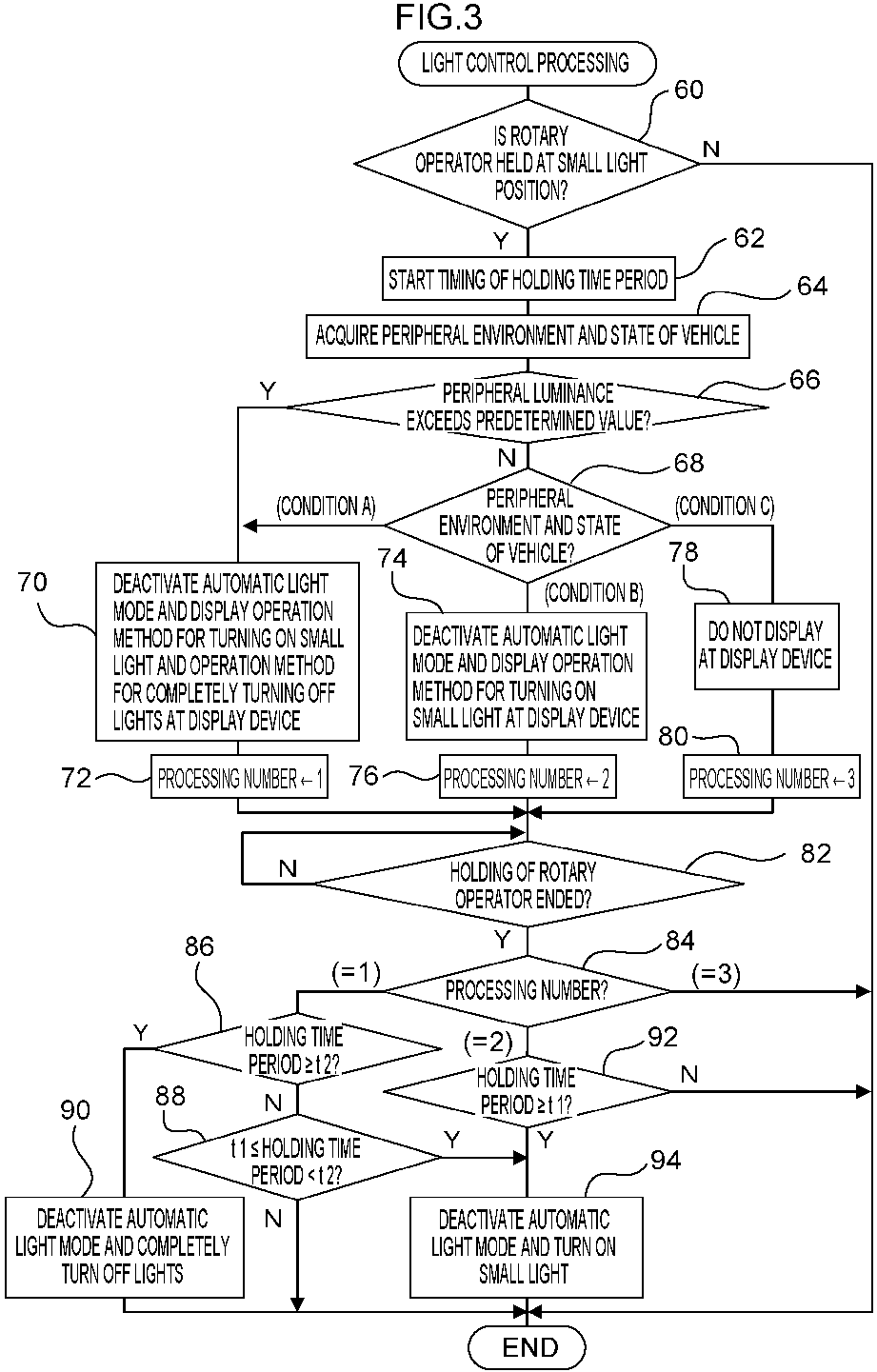
Fig. 3 is a flowchart illustrating light control processing executed by a light control ECU; -
Fig. 4A is a conceptual diagram illustrating a state in which a rotary operator of an operation lever has been rotated to a small light position; -
Fig. 4B is a conceptual diagram illustrating a state in which a rotary operator of an operation lever is held at a small light position; -
Fig. 5A is a conceptual diagram illustrating an operation method that is displayed at a display device in a case in which a peripheral luminance exceeds a predetermined value, or in a case in which a peripheral luminance is less than or equal to a predetermined value, and a drive system of a vehicle is suspended or a shift position is in parking or a parking brake is in operation; and -
Fig. 5B is a conceptual diagram illustrating an operation method that is displayed at a display device under the conditions that a peripheral luminance is less than or equal to a predetermined value, a shift position is not in parking, and a parking brake is not in operation. - Detailed explanation follows of an example of an exemplary embodiment of the present disclosure, with reference to the drawings. An
onboard system 10 illustrated inFig. 1 is installed at a vehicle, and includes a vehicle speed determination electronic control unit (ECU) 12, a shiftposition determination ECU 14, aparking brake ECU 16, a surroundingenvironment determination ECU 18, adisplay device 20, and alight control ECU 22. The vehiclespeed determination ECU 12, the shiftposition determination ECU 14, theparking brake ECU 16, the surroundingenvironment determination ECU 18, thedisplay device 20, and thelight control ECU 22 are connected via a communication line (for example, a controller area network (CAN) bus). - Although not illustrated in the drawings, the above-described ECUs respectively include a central processing unit (CPU), memory such as read only memory (ROM), or random access memory (RAM), and a non-volatile storage section such as a hard disk drive (HDD) or a solid state drive (SSD).
- The vehicle speed determination ECU 12 acquires a detection signal from a vehicle speed sensor, which is not illustrated in the drawings, and determines a vehicle speed of the vehicle based on the acquired detection signal. The shift
position determination ECU 14 acquires a detection signal from a shift position sensor, which is not illustrated in the drawings, and determines a shift position of the vehicle based on the acquired detection signal. Theparking brake ECU 16 acquires a detection signal from a parking brake sensor, which is not illustrated in the drawings, and determines an operating state (in operation/not in operation) of a parking brake of the vehicle based on the acquired detection signal. - The surrounding environment determination ECU 18 acquires a detection signal from a sensor, which is not illustrated in the drawings, that detects the luminance around the vehicle, and based on the acquired detection signal, determines the luminance around the vehicle as the surrounding environment of the vehicle. As the above-described sensors, a luminance sensor that is provided at the vehicle in order to perform automatic-light control in which a headlight of the vehicle is turned on and off in accordance with the luminance around the vehicle, or a camera that is provided at the vehicle to image the surroundings of the vehicle, can be applied.
- It should be noted that the surrounding environment determination ECU 18 may be configured to estimate the luminance around the vehicle by acquiring weather information from an external weather information server or the like, and determining day and night from the acquired weather information and/or determining the weather to be fine weather, cloudy weather or the like. Further, the surrounding environment determination ECU 18 may be configured to estimate the luminance around the vehicle by acquiring a current position of the vehicle from, for example, a global navigation satellite system (GNSS) device, and determining whether or not the vehicle is traveling through a tunnel.
- The
display device 20 is a display that enables thelight control ECU 22 to display an operation method of anoperation lever 32 for deactivating an automatic light mode. As thedisplay device 20, for example, a meter display provided at an instrument panel of the vehicle can be applied. Alight switch 34, which is incorporated at theoperation lever 32, is connected to thelight control ECU 22 via a communication line such as a CAN bus, and aheadlight device 26 is also connected to thelight control ECU 22. Theheadlight device 26 is provided with aheadlight 28 and a small light (also referred to as a position light) 30. - As illustrated in
Fig. 2 , theoperation lever 32 includes a levermain body 36 and arotary operator 38. The levermain body 36 is a rod-shaped member, and is supported at a side portion of a steering column of the vehicle such that the levermain body 36 is able to operate to tilt in a vehicle front-rear direction and a vehicle vertical direction. In a case in which the axis of the levermain body 36 is tilted, thelight control ECU 22 switches the optical axis of theheadlight 28 or turns on or off a turn signal lamp in accordance with a direction in which the levermain body 36 is tilted. Thelight switch 34 is incorporated at the lever main body 36 (seeFig. 1 ). - The
rotary operator 38 is provided at a distal end portion of the levermain body 36 so as to be rotatable around the axis of the levermain body 36. As illustrated inFig. 4A and Fig. 4B , as rotation positions of therotary operator 38, a light ON position (HEAD) 40 for instructing constant lighting of theheadlight 28 and thesmall light 30, an automatic light position (AUTO) 42 for setting an automatic light mode in which the turning on and off of theheadlight 28 and thesmall light 30 is controlled based on the luminance around the vehicle, and asmall light position 44 for instructing to switch to a small light lighting mode in which thesmall light 30 is turned on are provided in this order along the rotation direction of therotary operator 38. - The contact points of the
light switch 34 are switched by a user, who is an occupant of the vehicle, rotating therotary operator 38. Thelight switch 34 then outputs, to thelight control ECU 22, switch contact information that indicates which one of the light ONposition 40, the automaticlight position 42, or the smalllight position 44 therotary operator 38 is positioned at. - In a case in which the
rotary operator 38 is positioned at the light ONposition 40, therotary operator 38 is held at the light ONposition 40 even if there is no longer an operation force of a rotation operation by the user. Moreover, in a case in which therotary operator 38 is positioned at the automaticlight position 42, therotary operator 38 is held at the automaticlight position 42 even if there is no longer the operation force of the rotation operation by the user. - On the other hand, the
light switch 34 is provided with a momentary mechanism that, in a case in which therotary operator 38 is positioned between the automaticlight position 42 and the smalllight position 44, automatically returns therotary operator 38 to the automaticlight position 42 when there is no longer the operation force of the rotation operation by the user. The momentary mechanism can be implemented by, for example, using a spring mechanism, which is not illustrated in the drawings, to continuously apply a rotation urging force to therotary operator 38 at the smalllight position 44 toward an automaticlight position 42 side to an extent that enables the user to perform a rotation operation. - The storage section of the
light control ECU 22 stores a light control program that is not illustrated in the drawings. Thelight control ECU 22 functions as thelight control section 24 illustrated inFig. 1 by reading the light control program from the storage section and loading the light control program in the memory, and the light control program that has been loaded in the memory being executed by the CPU. - Based on the switch contact information that is input from the
light switch 34, in a case in which therotary operator 38 is positioned at the light ONposition 40, thelight control section 24 turns on all of theheadlights 28 and thesmall lights 30 regardless of the luminance around the vehicle (day or night). Moreover, in a case in which therotary operator 38 is positioned at the automaticlight position 42, if the luminance around the vehicle exceeds a predetermined value (during daytime or the like), thelight control section 24 turns off all of theheadlights 28 and thesmall lights 30, and if the luminance around the vehicle is less than or equal to a predetermined value, thelight control section 24 turns on all of theheadlights 28 and the small lights 30. - Moreover, in a case in which the
rotary operator 38 is held at the smalllight position 44 against the rotation urging force of the momentary mechanism, thelight control section 24 performs the light control processing described below. It should be noted that theoperation lever 32, which includes the levermain body 36 and therotary operator 38, and thelight control ECU 22, which functions as thelight control section 24, are examples of a light control device according to the present disclosure. - Next, as operation of the present exemplary embodiment, explanation follows regarding light control processing that is executed by the
light control section 24, with reference toFig. 3 . It should be noted that the light control processing is repeatedly executed by thelight control section 24 while a user is onboard the vehicle. - At
step 60 of the light control processing, thelight control section 24 determines whether or not therotary operator 38 is held at the smalllight position 44 against the rotation urging force of the momentary mechanism. In a case in which the determination atstep 60 is negative, the light control processing is ended. On the other hand, after therotary operator 38 has been rotated to the smalllight position 44 against the rotation urging force of the momentary mechanism as illustrated by the arrow A inFig. 4A , in a case in which therotary operator 38 is held at the smalllight position 44 as illustrated inFig. 4B , the determination atstep 60 is affirmative, and the processing transitions to step 62. Atstep 62, thelight control section 24 starts timing a period of time (a holding time period) during which therotary operator 38 is held at the smalllight position 44. - At
step 64, thelight control section 24 acquires the peripheral environment of the vehicle and the state of the vehicle. Namely, as the peripheral environment of the vehicle, thelight control section 24 acquires the luminance around the vehicle from the surroundingenvironment determination ECU 18. Further, thelight control section 24 acquires, as the state of the vehicle, the vehicle speed of the vehicle from the vehiclespeed determination ECU 12, acquires the shift position of the vehicle from the shiftposition determination ECU 14, and acquires the operating state of the parking brake of the vehicle from theparking brake ECU 16. Moreover, thelight control section 24 acquires a state of an ignition switch of the vehicle as the state of the vehicle. In a case in which the acquired state of the ignition switch of the vehicle is "OFF", thelight control section 24 determines that the drive system of the vehicle is suspended. - At
step 66, thelight control section 24 determines whether or not the peripheral luminance of the vehicle acquired atstep 64 exceeds a predetermined value. The predetermined value atstep 66 is set to a value for determining whether or not the peripheral environment is daytime or nighttime. Accordingly, atstep 66, it is determined whether or not the surroundings of the vehicle are daytime. In a case in which the determination atstep 66 is affirmative, the processing transitions to step 70, while in a case in which the determination atstep 66 is negative, the processing transitions to step 68. - At
step 68, thelight control section 24 branches the processing based on the peripheral environment of the vehicle and the state of the vehicle acquired atstep 64. More specifically, in a case in which the peripheral luminance of the vehicle is less than or equal to a predetermined value, and the drive system of the vehicle is suspended or the shift position is in parking or the parking brake is in operation (hereinafter referred to as "condition A"), the processing transitions to step 70. Further, in a case in which the peripheral luminance of the vehicle is less than or equal to the predetermined value and the shift position is not in parking and the parking brake is not in operation (hereinafter referred to as "condition B"), the processing transitions to step 74. Moreover, in a case in which the peripheral luminance of the vehicle is less than or equal to the predetermined value and the vehicle speed is higher than or equal to a predetermined vehicle speed (hereinafter referred to as "condition C"), the processing transitions to step 78. - In a case in which the processing transitions to step 70 from
step 66 or fromstep 68, as illustrated inFig. 5A , thelight control section 24 causes display of, at thedisplay device 20, an operation method of deactivating the automatic light mode and turning on thesmall light 30, and an operation method of deactivating the automatic light mode and completely turning off the lights. InFig. 5A , an operation method of deactivating the automatic light mode and turning on thesmall light 30 is an operation method of holding therotary operator 38 at the smalllight position 44 for one second (or longer). Further, an operation method of deactivating the automatic light mode and completely turning off the lights is an operation method of holding therotary operator 38 at the smalllight position 44 for two seconds (or longer). After performing the processing ofstep 70, thelight control section 24 sets the processing number to " 1" at thenext step 72, and the processing transitions to step 82. - Moreover, in a case in which the processing transitions from
step 68 to step 74, as illustrated inFig. 5B , thelight control section 24 causes display of, at thedisplay device 20, an operation method of deactivating the automatic light mode and turning on thesmall light 30. InFig. 5B , an operation method of deactivating the automatic light mode and turning on thesmall light 30 is an operation method of holding therotary operator 38 at the smalllight position 44 for one second (or longer). After performing the processing ofstep 74, thelight control section 24 sets the processing number to "2" at thenext step 76, and the processing transitions to step 82. - Further, in a case in which the processing transitions from
step 68 to step 78, thelight control section 24 does not cause display of an operation method at thedisplay device 20. Thelight control section 24 then sets the processing number to "3" at thenext step 80, and the processing transitions to step 82. - At
step 82, thelight control section 24 determines whether or not the operation of holding therotary operator 38 at the smalllight position 44 has ended. In a case in which the determination atstep 82 is negative,step 82 is repeated until the determination is affirmative. In a case in which the determination atstep 82 is affirmative, the timing of the holding time period is ended, and the processing transitions to step 84. Atstep 84, thelight control section 24 then determines the processing number, and branches the processing in accordance with the processing number. - In a case in which the processing number is 1, the processing transitions from
step 84 to step 86. Atstep 86, thelight control section 24 determines whether or not the measured holding time period is longer than or equal to a second time period t2. It should be noted that a time period of, for example, approximately 2 seconds is set as the second time period t2. In a case in which the determination atstep 86 is affirmative, the processing transitions to step 90. Atstep 90, thelight control section 24 deactivates the automatic light mode and completely turns off the lights, and ends the light control processing. - In a case in which the determination at
step 86 is negative, the processing transitions to step 88. Atstep 88, thelight control section 24 determines whether or not the holding time period is longer than or equal to a first time period tl and less than the second time period t2. It should be noted that a time of, for example, approximately 1 second is set as the first time period 11. In a case in which the determination atstep 88 is affirmative, the processing transitions to step 94. Then, atstep 94, thelight control section 24 deactivates the automatic light mode and turns on thesmall light 30, and ends the light control processing. Further, in a case in which the determination atstep 88 is negative, the light control processing is ended. - As described above, in a case in which the processing number is 1, that is, in a case in which the peripheral luminance of the vehicle exceeds the predetermined value, or in a case in which the above-described condition A is satisfied, the operation is performed in accordance with the operation method illustrated in
Fig. 5A . - Moreover, in a case in which the processing number is 2, the processing transitions from
step 84 to step 92. Atstep 92, thelight control section 24 determines whether or not the holding time period is longer than or equal to first time period 11. In a case in which the determination atstep 92 is affirmative, the processing transitions to step 94. Then, atstep 94, thelight control section 24 deactivates the automatic light mode and turns on thesmall light 30, and ends the light control processing. Further, in a case in which the determination atstep 92 is negative, the light control processing is ended. - As described above, in a case in which the processing number is 2, that is, in a case in which the above-described condition B is satisfied, the operation is performed in accordance with the operation method illustrated in
Fig. 5B . Further, in a case in which the processing number is 3, that is, in a case in which the above-described condition C is satisfied, the light control processing is ended. - As described above, in the present exemplary embodiment, the
rotary operator 38 is provided at the distal end portion of the levermain body 36, and is rotatable at least between the automaticlight position 42 for instructing to switch to the automatic light mode, and the smalllight position 44 for instructing to switch to the small light lighting mode in which the small light is turned on. Further, the levermain body 36 incorporates thelight switch 34 that is provided with the momentary mechanism that automatically returns therotary operator 38 to the automaticlight position 42 when there is no longer the rotation operation force on therotary operator 38 at a position between the automaticlight position 42 and the smalllight position 44. Moreover, in a case in which therotary operator 38 is at the smalllight position 44 for the first period of time, thelight control section 24 deactivates the automatic light mode and switches to the small light lighting mode, and in a case in which therotary operator 38 is at the smalllight position 44 for the second period of time, which is longer than the first period of time, thelight control section 24 deactivates the automatic light mode and switches to a light off mode in which the lights are completely turned off. Further, in a case in which therotary operator 38 is held at the smalllight position 44, in accordance with the peripheral environment and the state of the vehicle, thelight control section 24 performs one of: (1) causing display of, at thedisplay device 20, the operation condition for switching to the small light lighting mode and the operation condition for switching to the light off mode, (2) causing display of, at thedisplay device 20, the operation condition for switching to the small light lighting mode, or (3) not causing display of an operation condition at thedisplay device 20. This enables the user to recognize the operation condition by visually checking the operation condition that is displayed at thedisplay device 20, enabling the occurrence of an operation error to be suppressed even until the user learns the procedure of an operation. Moreover, complicated display at thedisplay device 20 can be suppressed.
Claims (4)
- A light control device, comprising:a rotary operator (38) that is rotatable at least between an automatic light position (42) for instructing to switch to an automatic light mode and a small light position (44) for instructing to switch to a small light lighting mode in which a small light is turned on;a lever main body portion (36) at which a light switch (34) is incorporated, the lever main body (36) having a distal end at which the rotary operator (38) is provided, and the light switch (34) being provided with a momentary mechanism configured to automatically return the rotary operator (38) to the automatic light position (42) when there is no longer a rotation operation force on the rotary operator (38) at a position between the automatic light position (42) and the small light position (44); anda light control section (24) configured to, in a case in which the rotary operator (38) is at the small light position (44) for a first period of time, deactivate the automatic light mode and switch to the small light lighting mode, and to, in a case in which the rotary operator (38) is at the small light position (44) for a second period of time, which is longer that the first period of time, deactivate the automatic light mode and switch to a light off mode in which lights are completely turned off,wherein, in a case in which the rotary operator (38) is held at the small light position (44), in accordance with a peripheral environment and a state of a vehicle, the light control section (24) is configured to perform one of:(1) causing display (70) of, at a display device (20), an operation condition for switching to the small light lighting mode and an operation condition for switching to the light off mode,(2) causing display (74) of, at the display device (20), the operation condition for switching to the small light lighting mode, or(3) not causing display (78) of an operation condition at the display device (20).
- The light control device according to claim 1, wherein:
in a case in which the rotary operator (38) is held at the small light position (44) and a peripheral luminance exceeds a predetermined value, or in a case in which the rotary operator (38) is held at the small light position (44), the peripheral luminance is less than or equal to the predetermined value, and a drive system of the vehicle is suspended or a shift position is in parking or a parking brake is in operation, the light control section (24) is configured to perform processing to (1) cause display (70) of, at the display device (20), the operation condition for switching to the small light lighting mode and the operation condition for switching to the light off mode. - The light control device according to claim 1 or 2, wherein:
in a case in which the rotary operator (38) is held at the small light position (44), a peripheral luminance is less than or equal to a predetermined value, a shift position is not in parking, and a parking brake is not in operation, the light control section (24) is configured to perform processing to (2) cause display (74) of, at the display device (20), the operation condition for switching to the small light lighting mode. - The light control device according to any one of claims 1 to 3, wherein:
in a case in which the rotary operator (38) is held at the small light position (44), a peripheral luminance is less than or equal to a predetermined value, and a vehicle speed is greater than or equal to a predetermined vehicle speed, the light control section (24) is configured to (3) not cause display (78) of an operation condition at the display device (20).
Applications Claiming Priority (1)
| Application Number | Priority Date | Filing Date | Title |
|---|---|---|---|
| JP2023188661A JP7838561B2 (en) | 2023-11-02 | 2023-11-02 | Light control device |
Publications (1)
| Publication Number | Publication Date |
|---|---|
| EP4549247A1 true EP4549247A1 (en) | 2025-05-07 |
Family
ID=93154356
Family Applications (1)
| Application Number | Title | Priority Date | Filing Date |
|---|---|---|---|
| EP24207229.6A Pending EP4549247A1 (en) | 2023-11-02 | 2024-10-17 | Light control device |
Country Status (2)
| Country | Link |
|---|---|
| EP (1) | EP4549247A1 (en) |
| JP (1) | JP7838561B2 (en) |
Citations (5)
| Publication number | Priority date | Publication date | Assignee | Title |
|---|---|---|---|---|
| DE102014011118A1 (en) * | 2014-07-26 | 2016-01-28 | Audi Ag | Method for operating a light function of motor vehicle headlights and motor vehicle with a display device and an operating element for operating the light function of the motor vehicle headlights |
| US20170297475A1 (en) * | 2014-09-05 | 2017-10-19 | Audi Ag | Lighting system for a motor vehicle and motor vehicle having a lighting system |
| EP3640088A1 (en) * | 2018-10-16 | 2020-04-22 | Toyota Jidosha Kabushiki Kaisha | Lever switch and automatic light control device |
| US20210284060A1 (en) * | 2020-03-16 | 2021-09-16 | Honda Motor Co., Ltd. | Vehicle light system |
| JP2023150252A (en) * | 2022-03-31 | 2023-10-16 | 三菱自動車工業株式会社 | light control device |
Family Cites Families (8)
| Publication number | Priority date | Publication date | Assignee | Title |
|---|---|---|---|---|
| JP2002002370A (en) * | 2000-06-21 | 2002-01-09 | Mitsubishi Motors Corp | Headlamp control device |
| KR101047663B1 (en) * | 2004-12-14 | 2011-07-08 | 현대자동차주식회사 | Combination switch structure and control method of vehicle |
| JP2008056056A (en) * | 2006-08-30 | 2008-03-13 | Denso Corp | Vehicle headlight control system |
| JP2008149755A (en) * | 2006-12-14 | 2008-07-03 | Matsushita Electric Ind Co Ltd | Vehicle operation display device |
| JP2014213695A (en) * | 2013-04-24 | 2014-11-17 | オムロンオートモーティブエレクトロニクス株式会社 | Operation switch of vehicle head light, and head light control device |
| DE102013215104A1 (en) * | 2013-08-01 | 2015-02-05 | Ford Global Technologies, Llc | Light switch unit, and method for controlling the exterior lighting of a motor vehicle |
| JP7274643B2 (en) * | 2020-03-16 | 2023-05-16 | 本田技研工業株式会社 | vehicle light system |
| JP7697285B2 (en) * | 2021-06-18 | 2025-06-24 | スズキ株式会社 | Vehicle headlamp mode selection device |
-
2023
- 2023-11-02 JP JP2023188661A patent/JP7838561B2/en active Active
-
2024
- 2024-10-17 EP EP24207229.6A patent/EP4549247A1/en active Pending
Patent Citations (6)
| Publication number | Priority date | Publication date | Assignee | Title |
|---|---|---|---|---|
| DE102014011118A1 (en) * | 2014-07-26 | 2016-01-28 | Audi Ag | Method for operating a light function of motor vehicle headlights and motor vehicle with a display device and an operating element for operating the light function of the motor vehicle headlights |
| US20170297475A1 (en) * | 2014-09-05 | 2017-10-19 | Audi Ag | Lighting system for a motor vehicle and motor vehicle having a lighting system |
| EP3640088A1 (en) * | 2018-10-16 | 2020-04-22 | Toyota Jidosha Kabushiki Kaisha | Lever switch and automatic light control device |
| JP2020062929A (en) | 2018-10-16 | 2020-04-23 | トヨタ自動車株式会社 | Lever switch and auto light control device |
| US20210284060A1 (en) * | 2020-03-16 | 2021-09-16 | Honda Motor Co., Ltd. | Vehicle light system |
| JP2023150252A (en) * | 2022-03-31 | 2023-10-16 | 三菱自動車工業株式会社 | light control device |
Also Published As
| Publication number | Publication date |
|---|---|
| JP7838561B2 (en) | 2026-04-01 |
| JP2025076795A (en) | 2025-05-16 |
Similar Documents
| Publication | Publication Date | Title |
|---|---|---|
| US7755294B2 (en) | Vehicle headlight beam controls | |
| US7759819B2 (en) | Illumination control device for vehicle | |
| US11383730B2 (en) | Method and device for assisting a driver during the deactivation of a highly automated driving mode of a vehicle | |
| US11661000B2 (en) | Lever switch and automatic light control device | |
| EP3763578B1 (en) | Vehicle-mounted equipment control device | |
| US12054090B2 (en) | Vehicle light system | |
| EP4549247A1 (en) | Light control device | |
| JP6942293B2 (en) | Vehicle display control device, vehicle display device, and vehicle display control method | |
| CN112776707A (en) | Method and system for reducing interference of music atmosphere lamp on steering view of driver | |
| JP7331788B2 (en) | headlamp controller | |
| JP4351132B2 (en) | In-vehicle night vision system | |
| JP7175321B2 (en) | Driving support device and driving support method | |
| US20200148109A1 (en) | Automated drive system | |
| US7131741B2 (en) | Automatic beam-axis adjustment system for vehicular headlights | |
| JP2018200593A (en) | Brake determination method and brake determination device | |
| JP7116670B2 (en) | TRIP CONTROL DEVICE, CONTROL METHOD AND PROGRAM | |
| KR20180065547A (en) | Apparatus for preventing vehicle collision and mehtod for controlling the same | |
| JP4609275B2 (en) | Vehicle headlight control device | |
| CN115230587B (en) | Auxiliary driving method and device for vehicle, electronic equipment and storage medium | |
| JP2025082400A (en) | Vehicle attitude calculation device and optical axis control device of headlight | |
| KR100302728B1 (en) | Road marker recognition device and the method for vehicle | |
| JP2020059294A (en) | Door mirror display control device | |
| JP2006001434A (en) | In-vehicle night vision system | |
| JP2018103677A (en) | Indicator light control device and computer program | |
| JP2008143421A (en) | Headlight control device |
Legal Events
| Date | Code | Title | Description |
|---|---|---|---|
| PUAI | Public reference made under article 153(3) epc to a published international application that has entered the european phase |
Free format text: ORIGINAL CODE: 0009012 |
|
| STAA | Information on the status of an ep patent application or granted ep patent |
Free format text: STATUS: REQUEST FOR EXAMINATION WAS MADE |
|
| 17P | Request for examination filed |
Effective date: 20241017 |
|
| AK | Designated contracting states |
Kind code of ref document: A1 Designated state(s): AL AT BE BG CH CY CZ DE DK EE ES FI FR GB GR HR HU IE IS IT LI LT LU LV MC ME MK MT NL NO PL PT RO RS SE SI SK SM TR |
|
| RIC1 | Information provided on ipc code assigned before grant |
Ipc: B60Q 1/00 20060101AFI20251220BHEP Ipc: B60Q 1/14 20060101ALN20251220BHEP |
|
| GRAP | Despatch of communication of intention to grant a patent |
Free format text: ORIGINAL CODE: EPIDOSNIGR1 |
|
| STAA | Information on the status of an ep patent application or granted ep patent |
Free format text: STATUS: GRANT OF PATENT IS INTENDED |
|
| INTG | Intention to grant announced |
Effective date: 20260312 |