EP4549233A1 - Monitoring system - Google Patents
Monitoring system Download PDFInfo
- Publication number
- EP4549233A1 EP4549233A1 EP23831011.4A EP23831011A EP4549233A1 EP 4549233 A1 EP4549233 A1 EP 4549233A1 EP 23831011 A EP23831011 A EP 23831011A EP 4549233 A1 EP4549233 A1 EP 4549233A1
- Authority
- EP
- European Patent Office
- Prior art keywords
- battery
- monitoring
- working machine
- area
- case
- Prior art date
- Legal status (The legal status is an assumption and is not a legal conclusion. Google has not performed a legal analysis and makes no representation as to the accuracy of the status listed.)
- Pending
Links
Images









Classifications
-
- A—HUMAN NECESSITIES
- A01—AGRICULTURE; FORESTRY; ANIMAL HUSBANDRY; HUNTING; TRAPPING; FISHING
- A01B—SOIL WORKING IN AGRICULTURE OR FORESTRY; PARTS, DETAILS, OR ACCESSORIES OF AGRICULTURAL MACHINES OR IMPLEMENTS, IN GENERAL
- A01B76/00—Parts, details or accessories of agricultural machines or implements, not provided for in groups A01B51/00 - A01B75/00
-
- B—PERFORMING OPERATIONS; TRANSPORTING
- B60—VEHICLES IN GENERAL
- B60L—PROPULSION OF ELECTRICALLY-PROPELLED VEHICLES; SUPPLYING ELECTRIC POWER FOR AUXILIARY EQUIPMENT OF ELECTRICALLY-PROPELLED VEHICLES; ELECTRODYNAMIC BRAKE SYSTEMS FOR VEHICLES IN GENERAL; MAGNETIC SUSPENSION OR LEVITATION FOR VEHICLES; MONITORING OPERATING VARIABLES OF ELECTRICALLY-PROPELLED VEHICLES; ELECTRIC SAFETY DEVICES FOR ELECTRICALLY-PROPELLED VEHICLES
- B60L15/00—Methods, circuits, or devices for controlling the traction-motor speed of electrically-propelled vehicles
-
- B—PERFORMING OPERATIONS; TRANSPORTING
- B60—VEHICLES IN GENERAL
- B60L—PROPULSION OF ELECTRICALLY-PROPELLED VEHICLES; SUPPLYING ELECTRIC POWER FOR AUXILIARY EQUIPMENT OF ELECTRICALLY-PROPELLED VEHICLES; ELECTRODYNAMIC BRAKE SYSTEMS FOR VEHICLES IN GENERAL; MAGNETIC SUSPENSION OR LEVITATION FOR VEHICLES; MONITORING OPERATING VARIABLES OF ELECTRICALLY-PROPELLED VEHICLES; ELECTRIC SAFETY DEVICES FOR ELECTRICALLY-PROPELLED VEHICLES
- B60L50/00—Electric propulsion with power supplied within the vehicle
- B60L50/50—Electric propulsion with power supplied within the vehicle using propulsion power supplied by batteries or fuel cells
- B60L50/60—Electric propulsion with power supplied within the vehicle using propulsion power supplied by batteries or fuel cells using power supplied by batteries
- B60L50/64—Constructional details of batteries specially adapted for electric vehicles
-
- B—PERFORMING OPERATIONS; TRANSPORTING
- B60—VEHICLES IN GENERAL
- B60L—PROPULSION OF ELECTRICALLY-PROPELLED VEHICLES; SUPPLYING ELECTRIC POWER FOR AUXILIARY EQUIPMENT OF ELECTRICALLY-PROPELLED VEHICLES; ELECTRODYNAMIC BRAKE SYSTEMS FOR VEHICLES IN GENERAL; MAGNETIC SUSPENSION OR LEVITATION FOR VEHICLES; MONITORING OPERATING VARIABLES OF ELECTRICALLY-PROPELLED VEHICLES; ELECTRIC SAFETY DEVICES FOR ELECTRICALLY-PROPELLED VEHICLES
- B60L53/00—Methods of charging batteries, specially adapted for electric vehicles; Charging stations or on-board charging equipment therefor; Exchange of energy storage elements in electric vehicles
- B60L53/60—Monitoring or controlling charging stations
- B60L53/68—Off-site monitoring or control, e.g. remote control
-
- B—PERFORMING OPERATIONS; TRANSPORTING
- B60—VEHICLES IN GENERAL
- B60L—PROPULSION OF ELECTRICALLY-PROPELLED VEHICLES; SUPPLYING ELECTRIC POWER FOR AUXILIARY EQUIPMENT OF ELECTRICALLY-PROPELLED VEHICLES; ELECTRODYNAMIC BRAKE SYSTEMS FOR VEHICLES IN GENERAL; MAGNETIC SUSPENSION OR LEVITATION FOR VEHICLES; MONITORING OPERATING VARIABLES OF ELECTRICALLY-PROPELLED VEHICLES; ELECTRIC SAFETY DEVICES FOR ELECTRICALLY-PROPELLED VEHICLES
- B60L53/00—Methods of charging batteries, specially adapted for electric vehicles; Charging stations or on-board charging equipment therefor; Exchange of energy storage elements in electric vehicles
- B60L53/80—Exchanging energy storage elements, e.g. removable batteries
-
- B—PERFORMING OPERATIONS; TRANSPORTING
- B60—VEHICLES IN GENERAL
- B60L—PROPULSION OF ELECTRICALLY-PROPELLED VEHICLES; SUPPLYING ELECTRIC POWER FOR AUXILIARY EQUIPMENT OF ELECTRICALLY-PROPELLED VEHICLES; ELECTRODYNAMIC BRAKE SYSTEMS FOR VEHICLES IN GENERAL; MAGNETIC SUSPENSION OR LEVITATION FOR VEHICLES; MONITORING OPERATING VARIABLES OF ELECTRICALLY-PROPELLED VEHICLES; ELECTRIC SAFETY DEVICES FOR ELECTRICALLY-PROPELLED VEHICLES
- B60L58/00—Methods or circuit arrangements for monitoring or controlling batteries or fuel cells, specially adapted for electric vehicles
- B60L58/10—Methods or circuit arrangements for monitoring or controlling batteries or fuel cells, specially adapted for electric vehicles for monitoring or controlling batteries
-
- B—PERFORMING OPERATIONS; TRANSPORTING
- B60—VEHICLES IN GENERAL
- B60Q—ARRANGEMENT OF SIGNALLING OR LIGHTING DEVICES, THE MOUNTING OR SUPPORTING THEREOF OR CIRCUITS THEREFOR, FOR VEHICLES IN GENERAL
- B60Q9/00—Arrangement or adaptation of signal devices not provided for in one of main groups B60Q1/00 - B60Q7/00, e.g. haptic signalling
-
- B—PERFORMING OPERATIONS; TRANSPORTING
- B62—LAND VEHICLES FOR TRAVELLING OTHERWISE THAN ON RAILS
- B62D—MOTOR VEHICLES; TRAILERS
- B62D49/00—Tractors
-
- G—PHYSICS
- G06—COMPUTING OR CALCULATING; COUNTING
- G06Q—INFORMATION AND COMMUNICATION TECHNOLOGY [ICT] SPECIALLY ADAPTED FOR ADMINISTRATIVE, COMMERCIAL, FINANCIAL, MANAGERIAL OR SUPERVISORY PURPOSES; SYSTEMS OR METHODS SPECIALLY ADAPTED FOR ADMINISTRATIVE, COMMERCIAL, FINANCIAL, MANAGERIAL OR SUPERVISORY PURPOSES, NOT OTHERWISE PROVIDED FOR
- G06Q10/00—Administration; Management
- G06Q10/06—Resources, workflows, human or project management; Enterprise or organisation planning; Enterprise or organisation modelling
-
- G—PHYSICS
- G06—COMPUTING OR CALCULATING; COUNTING
- G06Q—INFORMATION AND COMMUNICATION TECHNOLOGY [ICT] SPECIALLY ADAPTED FOR ADMINISTRATIVE, COMMERCIAL, FINANCIAL, MANAGERIAL OR SUPERVISORY PURPOSES; SYSTEMS OR METHODS SPECIALLY ADAPTED FOR ADMINISTRATIVE, COMMERCIAL, FINANCIAL, MANAGERIAL OR SUPERVISORY PURPOSES, NOT OTHERWISE PROVIDED FOR
- G06Q50/00—Information and communication technology [ICT] specially adapted for implementation of business processes of specific business sectors, e.g. utilities or tourism
- G06Q50/02—Agriculture; Fishing; Forestry; Mining
-
- B—PERFORMING OPERATIONS; TRANSPORTING
- B60—VEHICLES IN GENERAL
- B60L—PROPULSION OF ELECTRICALLY-PROPELLED VEHICLES; SUPPLYING ELECTRIC POWER FOR AUXILIARY EQUIPMENT OF ELECTRICALLY-PROPELLED VEHICLES; ELECTRODYNAMIC BRAKE SYSTEMS FOR VEHICLES IN GENERAL; MAGNETIC SUSPENSION OR LEVITATION FOR VEHICLES; MONITORING OPERATING VARIABLES OF ELECTRICALLY-PROPELLED VEHICLES; ELECTRIC SAFETY DEVICES FOR ELECTRICALLY-PROPELLED VEHICLES
- B60L2200/00—Type of vehicles
- B60L2200/40—Working vehicles
Definitions
- the present invention relates to a monitoring system of a storing device that stores an energy source for driving a working machine including, for example, an agricultural machine, a construction machine, and the like.
- a monitoring system of Patent Literature 1 is known as a system for monitoring a working machine such as an agricultural machine.
- the monitoring system of Patent Literature 1 includes a notification unit that makes a notification for a working body based on whether or not the working body is located in an area determined for the working body. As a result, in a case where it is determined that the working body is located outside the area, the notification for the working body is made, so that the working body can be easily monitored.
- Patent Literature 1 JP 2021-106555 A (claim 1 and the like)
- a prime mover for example, a motor or the like may be used.
- a battery or the like that supplies electric energy to the prime mover is often used.
- Such a type of battery or the like may be replaceable.
- a case in which a new replacement battery or the like is left in a farm field or the like in advance or a used battery or the like is left in the farm field or the like for efficient work is assumed. That is, the battery or the like may be left at a position different from a position of the working machine performing work. In this case, there is a great demand for monitoring the battery and the like. In addition, there is a great demand for monitoring the battery or the like even in a state in which the battery or the like is mounted on the working machine. It is difficult for the technology described in Patent Literature 1 to meet the above demand.
- an object of the present invention is to provide a monitoring system capable of easily monitoring a storing device that stores an energy source for driving a working machine.
- a monitoring system includes: a storing device that stores an energy source for driving a working machine; and a monitoring device including an area setting unit that sets an area for the storing device, and a first monitoring unit that monitors the storing device by making a notification for the storing device or a restriction for the storing device in a case where the storing device is not located in the set area.
- the storing device is attachable to and detachable from the working machine, and the first monitoring unit makes the notification for the storing device in a case where the storing device that is not mounted on the working machine is not located in the set area.
- the storing device is attachable to and detachable from the working machine, and the first monitoring unit restricts replenishment of the storing device with the energy source in a case where the storing device that is not mounted on the working machine is not located in the set area.
- the storing device is attachable to and detachable from the working machine, and the first monitoring unit restricts supply of the energy source to the working machine in a case where the storing device mounted on the working machine is not located in the set area.
- the storing device is attachable to and detachable from the working machine, and the first monitoring unit restricts attachment and detachment of the storing device to and from the working machine in a case where the storing device mounted on the working machine is not located in the set area.
- the storing device is attachable to and detachable from the working machine and is conveyable in a state of not being mounted on the working machine, and the first monitoring unit cancels the monitoring in a case where the storing device for replacing the storing device mounted on the working machine is conveyed, and the first monitoring unit starts the monitoring in a case where the storing device for the replacement is mounted on the working machine while the monitoring is cancelled.
- the first monitoring unit maintains the monitoring in a case where the monitoring is started, and the first monitoring unit cancels the monitoring in a case where the storing device that is not mounted on the working machine is conveyed while the monitoring is maintained.
- the storing device mounted on the working machine is replaced such that the energy source for maintaining the monitoring remains.
- the monitoring device includes a second monitoring unit that monitors whether or not the working machine is located in the area, the area setting unit sets the area for the storing device based on a position of the working machine, and the first monitoring unit performs the monitoring of the storing device in a case where the second monitoring unit performs the monitoring of the working machine.
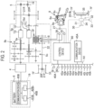
- Fig. 1 shows a working machine and a monitoring system that monitors a battery of the working machine.
- the monitoring system includes a monitoring device 100.
- the monitoring device 100 is a device that monitors a working machine 101 and a battery 6.
- the working machine 101 includes an agricultural machine 101a such as a tractor, a combine harvester, or a rice transplanter, and an implement 101b couplable to the agricultural machine 101a (see Fig. 20 ).
- the monitoring device 100 is an installation type computer such as a server, a portable type computer such as a smartphone, a tablet, or a notebook computer, or the like. In the present embodiment, the monitoring device 100 will be described as a server.
- the working machine 101 may be a construction machine or the like instead of the agricultural machine 101a.
- Fig. 20 is a side view showing a tractor which is one of the agricultural machines 101a, and the implement 101b mountable to the tractor.
- a front side of a driver seated on a driver seat 10 of the tractor will be described as a front side
- a rear side of the driver will be described as a rear side
- a left side of the driver will be described as a left side
- a right side of the driver will be described as a right side.
- a horizontal direction which is a direction orthogonal to a front-rear direction of the tractor, will be described as a vehicle body width direction.
- the tractor (agricultural machine 101a) includes a vehicle body 3, a prime mover 4, a transmission device 5, and a battery (storing device) 6.
- the vehicle body 3 includes a traveling device 7 and can travel.
- the traveling device 7 is a device including front wheels 7F and rear wheels 7R.
- the front wheel 7F may be a tire type or a crawler type.
- the rear wheel 7R may also be a tire type or a crawler type.
- the prime mover 4 is an electric motor.
- the prime mover 4 is driven by electric energy (energy source) supplied from the battery 6.
- the prime mover 4 and the battery 6 are disposed at a front portion of the vehicle body 3, and the battery 6 is attachable to and detachable from a battery mounting portion 19 included in the vehicle body 3 (see Fig. 4 ).
- the battery 6 mounted on the battery mounting portion 19 is replaceable, and details thereof are described below.
- the transmission device 5 can switch a propulsive force of the traveling device 7 by shifting, and can switch forward movement and backward movement of the traveling device 7.
- the driver seat 10 is provided at a rear portion of the vehicle body 3.
- a steering wheel 30 is provided at the front of the driver seat 10.
- a coupling portion configured by a three-point link mechanism or the like is provided at the rear portion of the vehicle body 3.
- the coupling portion is a lifting device 8 to and from which the working device (implement) 101b is attachable and detachable and which enables the working device (implement) 101b to travel.
- the implement 101b is coupled to the lifting device 8, enabling the vehicle body 3 to tow the implement 101b.
- the coupling portion may be a towing device that does not lift and lower the implement 101b.
- the implement 101b is a tilling device for tilling, a ridging device for ridging, a planting device for planting crops, a fertilizer spreading device for spreading a fertilizer, a pesticide spreading device for spreading a pesticide, a harvesting device for harvesting, a mowing device for mowing grass or the like, a distributing device for distributing grass or the like, a grass gathering device for gathering grass or the like, and a shaping device for shaping grass or the like.
- the transmission device 5 includes a main shaft (propulsion shaft) 5a, a main transmission unit 5b, an auxiliary transmission unit 5c, a shuttle unit 5d, a PTO power transmission unit 5e, and a front transmission unit 5f.
- the propulsion shaft 5a is rotatably supported by a housing case (transmission case) of the transmission device 5, and power from a crankshaft of the prime mover 4 is transmitted to the propulsion shaft 5a.
- the main transmission unit 5b includes a plurality of gears and a shifter that changes connection of the gears.
- the main transmission unit 5b changes and outputs (shifts) rotation input from the propulsion shaft 5a by appropriately changing connection (meshing) of the plurality of gears with the shifter.
- the auxiliary transmission unit 5c includes a plurality of gears and a shifter that changes connection of the gears.
- the auxiliary transmission unit 5c changes and outputs (shifts) rotation input from the main transmission unit 5b by appropriately changing connection (meshing) of the plurality of gears with the shifter.
- the shuttle unit 5d includes a shuttle shaft 12 and a forward/backward switching unit 13.
- the power output from the auxiliary transmission unit 5c is transmitted to the shuttle shaft 12 via a gear or the like.
- the forward/backward switching unit 13 is configured by, for example, a hydraulic clutch, and switches a rotation direction of the shuttle shaft 12, that is, forward movement and backward movement of the tractor by being turned on and off.
- the shuttle shaft 12 is connected to a rear wheel differential device 20R.
- the rear wheel differential device 20R rotatably supports a rear axle 21R to which the rear wheels 7R are attached.
- the PTO power transmission unit 5e includes a PTO propulsion shaft 14 and a PTO clutch 15.
- the PTO propulsion shaft 14 is rotatably supported, and can transmit power from the propulsion shaft 5a.
- the PTO propulsion shaft 14 is connected to the PTO shaft 16 via a gear or the like.
- the PTO clutch 15 is configured by, for example, a hydraulic clutch, and is switched between a state in which the power of the propulsion shaft 5a is transmitted to the PTO propulsion shaft 14 and a state in which the power of the propulsion shaft 5a is not transmitted to the PTO propulsion shaft 14 by being turned on and off.
- the front transmission unit 5f includes a first clutch 17 and a second clutch 18.
- the first clutch 17 and the second clutch 18 can transmit the power from the propulsion shaft 5a, and for example, the power of the shuttle 12 is transmitted via a gear and a transmission shaft.
- the power from the first clutch 17 and the second clutch 18 can be transmitted to a front axle 21F via a front transmission shaft 22.
- the front transmission shaft 22 is connected to a front wheel differential device 20F, and the front wheel differential device 20F rotatably supports the front axle 21F to which front wheels 7F are attached.
- the first clutch 17 and the second clutch 18 are configured by a hydraulic clutch or the like.
- An oil passage is connected to the first clutch 17, and the oil passage is connected to a first operation valve 25 to which hydraulic oil discharged from a hydraulic pump is supplied.
- the first clutch 17 is switched between a connected state and a disconnected state depending on an opening degree of the first operation valve 25.
- An oil passage is connected to the second clutch 18, and a second operation valve 26 is connected to the oil passage.
- the second clutch 18 is switched between the connected state and the disconnected state depending on an opening degree of the second operation valve 26.
- the first operation valve 25 and the second operation valve 26 are, for example, solenoid valve equipped two-position switching valves, and are switched to the connected state or the disconnected state by exciting or demagnetizing a solenoid of the solenoid valve.
- the lifting device 8 includes a lift arm 8a, a lower link 8b, a top link 8c, a lift rod 8d, and a lift cylinder 8e.
- a front end portion of the lift arm 8a is swingably supported upward or downward on a rear upper portion of the case (transmission case) that houses the transmission device 5.
- the lift arm 8a swings (is lifted and lowered) by driving of the lift cylinder 8e.
- the lift cylinder 8e is configured by a hydraulic cylinder.
- the lift cylinder 8e is connected to a hydraulic pump via a control valve 27.
- the lift cylinder 8e is switched between the connected state and the disconnected state depending on an opening degree of the control valve 27.
- the control valve 27 is, for example, a solenoid valve equipped two-position switching valve, and is switched to the connected state or the disconnected state by exciting or demagnetizing a solenoid of the solenoid valve.
- the control valve 27 is in the connected state, the lift cylinder 8e is driven (expanded and contracted) by the hydraulic pump, and when the control valve 27 is in the disconnected state, the driving of the lift cylinder 8e is restricted (locked).
- a front end portion of the lower link 8b is swingably supported upward or downward on a rear lower portion of the transmission device 5.
- a front end portion of the top link 8c is swingably supported upward or downward on a rear portion of the transmission device 5 above the lower link 8b.
- the lift rod 8d couples the lift arm 8a and the lower link 8b.
- the implement 101b is coupled to a rear portion of the lower link 8b and a rear portion of the top link 8c.
- the implement 101b swings upward or downward (is lifted or lowered) with a front portion of the lower link 8b as a fulcrum.
- the lifting and lowering of the implement 101b is also locked.
- the battery 6 includes a battery pack and an electric unit (a relay, a fuse, or the like) inside a substantially rectangular parallelepiped casing.
- the battery pack includes a plurality of battery modules.
- the battery module includes a plurality of cells.
- the battery 6 configured as described above is a battery capable of charging and discharging electric energy, specifically, a lithium ion battery.
- the battery 6 is held by a holder 6a from the outside of the casing, and a grip portion 6b is provided at a front side end portion of the holder 6a.
- the battery mounting portion 19 of the vehicle body 3 includes a housing portion 19a that is a space capable of housing the entire battery 6, an opening 19b provided on a front side of the housing portion 19a in the vehicle width direction, and a flap type lid portion 19c capable of closing the opening 19b. Normally, in a state in which the battery 6 is housed in the housing portion 19a, the opening 19b is closed by the lid portion 19c, and electric power can be supplied from the battery 6 to the tractor.
- the opening 19b is exposed by opening the lid portion 19c.
- the battery 6 is taken out from the housing portion 19a while being slid toward the front side in the vehicle width direction.
- a back side end portion of the new replacement battery 6 is inserted into the empty housing portion 19a through the opening 19b.
- the holder 6a is pushed toward a back side while gripping the grip portion 6b of the new replacement battery 6, and the new replacement battery 6 is slid toward the back side in the vehicle width direction.
- the opening 19b is closed by closing the lid portion 19c.
- the battery 6 is replaced.
- the configurations of the battery 6 and the battery mounting portion 19 are examples, and any configuration may be adopted as long as the battery 6 can be mounted on and separated from the battery mounting portion 19.
- the battery 6 is replaced.
- a package capable of storing the energy source may be replaced.
- a hydrogen tank, a liquified petroleum gas (LPG) tank, or the like may be used as the package.
- the hydrogen tank is loaded, for example, a fuel cell that generates electric power with hydrogen and oxygen in the air may be mounted on the tractor, and hydrogen from the tank may be supplied to the fuel cell.
- the LPG tank is loaded, for example, a generator that generates electric power by a gas engine may be mounted on the tractor, and gas from the tank may be supplied to the gas engine.
- the tractor includes a steering device 29.
- the steering device 29 includes a steering wheel 30, a rotation shaft (steering shaft) 31 that rotates with the rotation of the steering wheel 30, and an assist mechanism (power steering mechanism) 32 that assists the steering of the steering wheel 30.
- the assist mechanism 32 includes a hydraulic pump 33, a control valve 34 to which hydraulic oil discharged from the hydraulic pump 33 is supplied, and a steering cylinder 35 operated by the control valve 34.
- the control valve 34 is a solenoid valve that operates based on a control signal.
- the control valve 34 is, for example, a three-position switching valve that can be switched by movement of a spool or the like.
- the control valve 34 can also be switched by steering of the steering shaft 31.
- the steering cylinder 35 is connected to an arm (knuckle arm) that changes an orientation of the front wheel 7F.
- a switching position and an opening degree of the control valve 34 are switched according to the steering wheel 30, and a steering direction of the front wheel 7F can be changed by expanding and contracting the steering cylinder 35 to the left or right according to the switching position and the opening degree of the control valve 34.
- the steering device 29 described above is an example, and is not limited to the above-described configuration.
- the tractor includes a positioning device 40A.
- the positioning device 40A can detect its own position (positioning information including latitude and longitude) by a satellite positioning system (positioning satellite) such as D-GPS, GPS, GLONASS, BeiDou, Galileo, or Michibiki. That is, the positioning device 40A receives a satellite signal (a position of the positioning satellite, a transmission time, correction information, or the like) transmitted from the positioning satellite, and detects a position (for example, latitude and longitude) based on the satellite signal.
- the positioning device 40A includes a reception device 41 and an inertial measurement unit (IMU) 42.
- IMU inertial measurement unit
- the reception device 41 is a device that includes an antenna or the like and receives the satellite signal transmitted from the positioning satellite, and is attached to the vehicle body 3 separately from the inertial measurement unit 42.
- the reception device 41 is attached to a cabin 9 provided in the vehicle body 3. Note that an attachment location of the reception device 41 is not limited to that in the embodiment.
- the inertial measurement unit 42 includes an acceleration sensor that detects an acceleration, a gyro sensor that detects an angular velocity, and the like.
- the inertial measurement unit 42 is provided below the vehicle body 3, for example, the driver seat 10, and can detect a roll angle, a pitch angle, a yaw angle, and the like of the vehicle body 3.
- the tractor includes a communication device 45A.
- the communication device 45A is connected to the positioning device 40A, a control device 60, an operation member (a lever, a switch, a dial, or the like), and sensors via an in-vehicle communication network N1, and an electric signal is input to the communication device 45A.
- the communication device 45A can communicate with an external network (outside) different from the in-vehicle communication network N1.
- the communication device 45A can perform radio communication by, for example, wireless fidelity (Wi-Fi) (registered trademark) of the IEEE 802.11 series which is a communication standard, Bluetooth (registered trademark) low energy (BLE), low power wide area (LPWA), low-power wide-area network (LPWAN), or the like.
- Wi-Fi wireless fidelity
- BLE Bluetooth
- LPWA low power wide area
- LPWAN low-power wide-area network
- the communication device 45A can perform radio communication by, for example, a mobile phone communication network, a data communication network, or the like.
- the communication device 45A transmits a vehicle body position (a position of the tractor) detected by the positioning device 40A to the monitoring device 100.
- the communication device 45A transmits, to the monitoring device 100, a working machine monitoring signal for monitoring whether or not the working machine 101 is in an area, a battery monitoring signal for monitoring whether or not the battery 6 is in the area, and a battery monitoring cancellation signal for cancelling monitoring of the battery 6.
- the battery 6 includes a positioning device 40B.
- the positioning device 40B has a configuration similar to that of the positioning device 40A. That is, the positioning device 40B receives a satellite signal (a position of the positioning satellite, a transmission time, correction information, or the like) transmitted from the positioning satellite, and detects a position (for example, latitude and longitude) based on the satellite signal.
- the positioning device 40B includes a reception device 41B and an inertial measurement unit 42B, and obtains the position by the reception device 41 and the inertial measurement unit 42.
- the reception device 41B is a device that includes an antenna or the like and receives the satellite signal transmitted from the positioning satellite, and is attached to the battery 6 separately from the inertial measurement unit 42B. In the embodiment, the reception device 41B is attached to the outer surface of the battery 6. Note that an attachment location of the reception device 41B is not limited to that in the embodiment.
- the battery 6 includes a communication device 45B.
- the communication device 45B can communicate with an external network (outside) different from the in-vehicle network N1.
- the communication device 45B can perform radio communication by, for example, wireless fidelity (Wi-Fi) (registered trademark) of the IEEE 802.11 series which is a communication standard, Bluetooth (registered trademark) low energy (BLE), low power wide area (LPWA), low-power wide-area network (LPWAN), or the like.
- Wi-Fi wireless fidelity
- BLE Bluetooth
- LPWA low power wide area
- LPWAN low-power wide-area network
- the communication device 45B can perform radio communication by, for example, a mobile phone communication network, a data communication network, or the like.
- the communication device 45B transmits a position (a position of the battery 6) detected by the positioning device 40B to the monitoring device 100.
- the positioning device 40B and the communication device 45B are provided in each of the battery 6 mounted on the tractor and the battery 6 that is not mounted on the tractor, that is, the new replacement battery 6 and the used battery 6.
- the electric energy is supplied to the positioning device 40B and the communication device 45B from the battery 6 in which the positioning device 40B and the communication device 45B are provided. That is, in a case where the electric energy of the battery 6 remains, the detected position of the battery 6 can be transmitted to the monitoring device 100.
- the tractor includes the control device 60.
- the control device 60 includes a computation unit (a central processing unit (CPU) or the like), a storage unit (memory), and the like, and performs predetermined control based on a program stored in the storage unit. More specifically, the control device 60 controls a traveling system or work system of the tractor based on an operation signal when the operation member (the lever, the switch, the dial, or the like) installed around the driver seat 10 is operated, detection signals of various sensors loaded on the vehicle body 3, and the like.
- the operation member the lever, the switch, the dial, or the like
- the control device 60 switches the forward/backward switching unit 13 to forward movement to move the vehicle body 3 forward.
- the control device 60 switches the forward/backward switching unit 13 to backward movement to move the vehicle body 3 backward.
- the control device 60 starts the prime mover 4 through predetermined processing, and in a case where the ignition switch 43b is operated to be turned off, the control device 60 stops the driving of the prime mover 4.
- the control device 60 switches a position of the PTO clutch 15 to one of a neutral position, an ON position, and an OFF position to turn on and off the driving of the PTO shaft 16.
- the control device 60 changes a rotation speed (referred to as a PTO rotation speed) of the PTO shaft 16 by switching a PTO shift gear embedded in the transmission device 5.
- the control device 60 automatically switches any one of the main transmission unit 5b or the auxiliary transmission unit 5c according to a state of the tractor, and automatically changes a shift stage (shift level) of the transmission device 5 to a predetermined shift stage (shift level).
- the shift changeover switch 43e is switched to manual shift, the control device 60 automatically switches any one of the main transmission unit 5b or the auxiliary transmission unit 5c according to a shift stage (shift level) set by a shift lever 43f and changes the shift stage of the transmission device 5.
- the control device 60 changes a vehicle speed (speed) of the vehicle body 3 by changing a rotation speed of the prime mover 4 (referred to as a prime mover rotation speed) according to an operation amount of the accelerator lever 43g.
- control device 60 controls the control valve 27 to expand the lift cylinder 8e and lift a rear end portion (an end portion adjacent to the implement 101b) of the lift arm 8a.
- control device 60 controls the control valve 27 to contract the lift cylinder 8e and lower the rear end portion (the end portion adjacent to the implement 101b) of the lift arm 8a.
- the control device 60 is set to an automated driving mode in a case where a driving changeover switch 43i is operated to be turned on, and is set to a manual driving mode in a case where the driving changeover switch 43i is operated to be turned off.
- the control device 60 performs automated driving of the tractor.
- the control device 60 automatically changes a rotation angle of the steering shaft (rotation shaft) 31 based on a deviation between the detected vehicle body position and a set scheduled travel route.
- the control device 60 automatically changes the shift stage of the transmission device 5, the rotation speed of the prime mover 4, and the like such that the current vehicle speed matches a vehicle speed corresponding to the scheduled travel route.
- the vehicle body 3 can perform automated driving on the scheduled travel route.
- the control device 60 acquires a remaining level of the battery 6 being mounted based on a potential detected by a potential sensor 43j of the battery 6, the rotation speed of the prime mover 4, the vehicle speed of the vehicle body 3, and the like. In a case where the control device 60 determines that replacement of the battery 6 being mounted is necessary based on the acquired remaining level of the battery 6, the control device 60 controls the communication device 45A to transmit the battery monitoring cancellation signal to the monitoring device 100. When the control device 60 determines that the mounted battery 6 has been replaced with the replacement battery 6 based on the potential detected by the potential sensor 43j of the battery 6, the control device 60 controls the communication device 45A to transmit the battery monitoring signal to the monitoring device 100. A specific aspect of the transmission of the battery monitoring signal and the battery monitoring cancellation signal based on the potential sensor 43j is described below.
- the control device 60 controls the communication device 45A to transmit the working machine monitoring signal.
- the working machine monitoring switch 43k may be configured as a switch that can be turned on and off, and the control device 60 may transmit the working machine monitoring signal in a case where the working machine monitoring switch 43k is turned on, and transmit, to the monitoring device 100, a working machine monitoring cancellation signal for cancelling the monitoring of the working machine 101 in a case where the working machine monitoring switch 43k is turned off.
- the prime mover 4 is driven by the battery 6.
- the battery 6 As the tractor travels and the work of the working device 101b progresses, the remaining level of the battery 6 being mounted decreases.
- the battery 6 is replaced in the farm field.
- the replacement of the battery 6 may be performed, for example, in an area A that is outside a work area of a farm field F and is in contact with an agricultural road R (see Figs. 7 , 8 , 9 , and the like).
- the "area A that is in contact with the agricultural road R" can be an area for replenishing the working device 101b with the material.
- the working machine 101 performing the work is moved to the area A.
- the working machine 101 performing the work may be moved to the area A in order to replace the battery 6. That is, an area for material replenishment can be used as an area for replacement of the battery 6.
- the battery 6 that is not mounted is stored in a delivery base (delivery center) away from the farm field F.
- the delivery base it is possible to store the replacement battery 6 to be delivered toward the farm field F, or to charge the used battery 6 collected in the farm field F.
- the delivery of the replacement battery 6 and the collection of the used battery 6 are performed by a transport vehicle such as a truck that can be loaded with and transport the battery 6.
- the replacement battery 6 is a battery that is sufficiently charged, for example, a battery whose charge amount is 80% or more in a case where the maximum charge amount of the battery is 100%. Note that the charge amount is not limited to 80% or more.
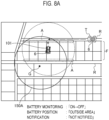
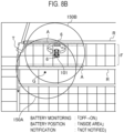
- the replacement battery 6 stored in the delivery base is loaded on a transport vehicle T, and as shown in Fig. 8(a) , the transport vehicle T travels from the delivery base toward the farm field F and reaches the area A of the farm field F that is in contact with the agricultural road R. Then, as shown in Fig. 8(b) , in the area A (for example, the area for material replenishment), the battery 6 loaded on the transport vehicle T is unloaded as the replacement battery 6. On the other hand, the battery 6 separated from the working machine 101 is left as the used battery 6 in the area A, and the replacement battery 6 that has already been left is mounted on the working machine 101. Note that the transport vehicle T after unloading moves to another farm field and collects another battery, and then returns to the delivery base.
- the used battery 6 that has been left is loaded on the transport vehicle T that has reached the area A via the agricultural road R, and the transport vehicle T travels toward the delivery base.
- the unloading of the battery 6 from the transport vehicle T and the loading of the battery 6 on the transport vehicle T may be performed by a driver of the transport vehicle T.
- the separation of the mounted battery 6 from the working machine 101 and the mounting of the replacement battery 6 on the working machine 101 may be performed by the driver of the tractor, or may be performed by the driver of the transport vehicle T as a service of the delivery base.
- a computer 106 is installed in the delivery base (delivery center).
- the computer 106 and the communication device 45A of the working machine (tractor) 101 can communicate with each other via a network or the like.
- the computer 106 acquires various information (hereinafter, referred to as delivery information) regarding delivery, and controls various equipment and devices installed in the delivery base (delivery center) based on the acquired delivery information.
- the delivery information includes an instruction signal (request signal) for requesting delivery of the battery 6, an instruction signal (collection signal) for requesting collection of the battery 6, the vehicle body position of the working machine (tractor) 101, and the like.
- the request signal, the collection signal, and the vehicle body position are transmitted from the communication device 45A of the working machine (tractor) 101, for example, and are received (acquired) by the computer 106.
- the control device 60 determines that the remaining level of the battery 6 being mounted is lower than a predetermined value and replacement of the battery 6 being mounted is necessary, the control device 60 instructs the communication device 45A to transmit the request signal and the vehicle body position, and the communication device 45A transmits the request signal and a vehicle body signal to the computer 106 (delivery base).
- the computer 106 that has received the request signal and the vehicle body position displays information indicating that "there is a battery delivery request" and the vehicle body position on a display unit 106A such as a monitor of the computer 106.
- a display unit 106A such as a monitor of the computer 106.
- an operator confirms the above information displayed on the display unit 106A, and instructs a delivery driver to move toward the farm field corresponding to the vehicle body position and deliver the replacement battery 6.
- the control device 60 determines that the remaining level is restored by mounting of the battery 6 and the mounted battery 6 is replaced with the replacement battery 6 after a potential temporarily becomes zero by the separation of the battery 6 while the working machine 101 is stopped
- the control device 60 instructs the communication device 45A to transmit the collection signal and the vehicle body position
- the communication device 45A transmits the collection signal and the vehicle body signal to the computer 106 (delivery base).
- the computer 106 that has received the collection signal and the vehicle body position displays information indicating that "there is a battery collection request" and the vehicle body position on a display unit 106A such as a monitor of the computer 106.
- the operator confirms the above information displayed on the display unit 106A, and instructs the delivery driver to move toward the farm field corresponding to the vehicle body position and collect the used battery 6.
- the control device 60 controls a steering device 29 and the prime mover 4 to automatically move the tractor to the area A (for example, the area for material replenishment) of the farm field F that is in contact with the agricultural road R and stop in the area A in a case where the control device 60 determines that the remaining level of the battery 6 being mounted is lower than the predetermined value and replacement of the battery 6 being mounted is necessary during the operation of the working machine 101.
- the control device 60 performs, for example, control to operate a buzzer of the tractor in a case where the control device 60 determines that the remaining level of the battery 6 being mounted is lower than the predetermined value and replacement of the battery 6 being mounted is necessary during the operation of the tractor. As a result, the driver of the tractor can be prompted to move the tractor to the area A of the farm field F that is in contact with the agricultural road R.
- the battery 6 mounted on the working machine 101 when the battery 6 mounted on the working machine 101 is separated and left in the area A, the battery 6 is replaced such that the energy source for maintaining the driving of the positioning device 40B and the communication device 45B remains. As a result, the position of the battery 6 is transmitted from the battery 6 left in the area A to the monitoring device 100, and the monitoring of the battery 6 by the monitoring device 100 is maintained.
- the monitoring device 100 monitors the working machine 101 and the battery 6.
- the monitoring device (server) 100 includes an area setting unit 110 and an area storage device 111.
- the area setting unit 110 is configured by an electric/electronic circuit provided in the monitoring device 100, a program stored in the monitoring device 100, and the like.
- the area storage device 111 is configured by a nonvolatile memory or the like.
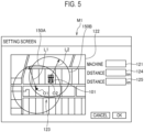
- the area setting unit 110 sets each of an area 150A of the working machine 101 and an area 150B of the battery 6. Specifically, as shown in Fig.
- the computer 105 is of an installation type, and may be a portable type computer such as a smartphone, a tablet, or a notebook computer.
- the setting screen M1 includes a working machine input section 121 for inputting the working machine 101, a map display section 122 for displaying a map, a pointer 123 for selecting an arbitrary point on the map, a working machine distance input section 124 for inputting a distance L1, and a battery distance input section 125 for inputting a distance L2.
- Identification information for identifying the working machine 101 can be input to the working machine input section 121.
- the identification information is various information such as a serial number, a name, a model number, a model, and a manufacturing number of the working machine 101.
- the map display section 122 is a portion that displays the map including a work site such as a road, an agricultural road, or a farm field, a building, and the like.
- the map may be, for example, a map acquired from a map providing company that provides map data, or may be a map created by the installation type computer 105 or the like, and is not limited thereto.
- the area 150A can be set for the working machine 101 by inputting working machine identification information, a center O1, and the distance L1 on the setting screen M1.
- a center of the area 150A is selected by the pointer 123 in the above-described embodiment, a plurality of positions (points) on the map may be selected by the pointer 123.
- the area setting unit 110 sets an area surrounded by a plurality of positions (points) as the area 150A.
- the area setting unit 110 sets the area 150B for the battery 6 based on a position of the working machine 101.
- Target batteries in the area 150B are the battery 6 being mounted on the tractor and the battery 6 that is not mounted on the tractor, and are the replacement battery 6 and the used battery 6.
- the distance L2 is input on the setting screen M1
- the area setting unit 110 sets a center O2 and the area 150B having the distance L2 with the vehicle body position transmitted from the communication device 45A as the center O2.
- the center O2 may be one point corresponding to one vehicle body position transmitted from the communication device 45 at a predetermined timing, or may be sequentially updated according to a change in the vehicle body position when the vehicle body 3 moves in the farm field or the like.
- the area setting unit 110 sets the center O2 of the area 150B at the same position as the vehicle body position, but the present invention is not limited thereto.
- the center O2 of the area 150B may be set at a position spaced apart from the vehicle body position by a predetermined distance.
- area information (the working machine identification information and information indicating the area 150A and the area 150B) of the tractor and the battery 6 set by the area setting unit 110 is stored in the area storage device 111.
- the area information shown in Fig. 6 is an example and is not limited.
- the monitoring device 100 includes a first monitoring unit 112 and a second monitoring unit 113.
- the first monitoring unit 112 monitors the battery 6 by making a notification for the battery 6. Therefore, the first monitoring unit 112 includes a notification unit 112A.
- the notification unit 112A is configured by an electric/electronic circuit provided in the monitoring device 100, a program stored in the monitoring device 100, and the like.
- the notification unit 112A makes the notification for the battery 6 based on whether or not the battery 6 is located in the area 150B determined for the battery 6. As shown in Figs. 7 , 8 , and 9 , it is assumed that the area 150B is set for the battery 6. In the area 150B, the center O2 and the distance L2 are set such that the vehicle body 3 is located at the center.
- the notification unit 112A determines whether or not the position of the battery 6 is in the area 150B.
- the “batteries 6" are the battery 6 being mounted on the tractor and the battery 6 that is not mounted on the tractor, and are the replacement battery 6 and the used battery 6.
- the second monitoring unit 113 monitors the working machine 101 by making a notification for the tractor. Therefore, the second monitoring unit 113 includes a notification unit 113A.
- the notification unit 113A is configured by an electric/electronic circuit provided in the monitoring device 100, a program stored in the monitoring device 100, and the like.
- the notification unit 113A makes the notification for the tractor based on whether or not the tractor is located in the area 150A determined for the working machine 101 (tractor). As shown in Figs. 7 , 8 , and 9 , it is assumed that the area 150A is set for the tractor. For example, the center O1 and the distance L1 are set such that a garage G is located at the center of the area 150A.
- the notification unit 113A determines whether or not the vehicle body position is within the area 150A.
- the notification unit 112A does not make a notification when the position of the battery 6 being mounted is within the area 150B.
- the notification unit 113A does not make a notification.
- the notification unit 112A determines that the position of the battery 6 being mounted is outside the area 150B, and notifies the installation type computer 105 or the like that "the battery is out of the area".
- the notification unit 113A determines that the vehicle body position is outside the area 150A, and notifies the installation type computer 105 or the like that "the tractor is out of the area”. Also in a case where the battery 6 that is not mounted deviates from the area 150B, a similar notification is made (see Fig. 8(c) ).
- the notification unit 112A monitors the battery 6 by notifying the installation type computer 105 or the like whether or not the battery 6 is in the area 150B determined corresponding to the battery 6.
- the notification unit 113A monitors the working machine 101 by notifying the installation type computer 105 or the like whether or not the working machine 101 is in the area 150A determined corresponding to the working machine 101.
- the battery 6 and the working machine 101 are outside the areas 150B and 150A for a long period of time, it can be determined that there is a possibility that the battery 6 and the working machine 101 have been stolen, and the theft of the battery 6 and the working machine 101 can be prevented by monitoring the battery 6 and the working machine 101.
- the above-described notification is made even in a case where the battery 6 is not stolen.
- a case where the battery 6 is not stolen but is intentionally located outside the area 150B may also be likely to be erroneously determined as theft. Therefore, when there is a high possibility of confusion with the occurrence of theft, and a user is accustomed to the above-described notification, there is a possibility of overlooking actual theft, and there is a high possibility of deteriorating security.
- the battery monitoring signal and the battery monitoring cancellation signal are transmitted to the monitoring device 100.
- the working machine monitoring signal is also transmitted to the monitoring device 100.
- transmission of the working machine monitoring signal, the battery monitoring signal, and the battery monitoring cancellation signal will be described.
- the control device 60 of the tractor controls the communication device 45A to transmit the working machine monitoring signal.
- the working machine monitoring switch 43k may be installed in a console of the cabin, for example, and may be operated by the driver of the tractor.
- the first monitoring unit 112 and the second monitoring unit 113 of the monitoring device 100 include a monitoring start unit 112B and a monitoring start unit 113B, respectively.
- the monitoring start unit 112B and the monitoring start unit 113B are configured by an electric/electronic circuit provided in the monitoring device 100, a program stored in the monitoring device 100, and the like.
- the monitoring start unit 113B of the second monitoring unit 113 starts monitoring in the area 150A of the working machine 101.
- the monitoring start unit 112A of the first monitoring unit 112 starts monitoring in the area 150B of the battery 6.
- the first monitoring unit 112 monitors the battery 6 in a case where the working machine 101 is monitored by the second monitoring unit 113.
- the control device 60 of the tractor controls the communication device 45A to transmit the battery monitoring cancellation signal when the control device 60 determines that the remaining level of the battery 6 being mounted is lower than the predetermined value and replacement of the battery 6 being mounted is necessary during the operation of the working machine 101.
- the first monitoring unit 112 of the monitoring device 100 includes a monitoring cancellation unit 112C.
- the monitoring cancellation unit 112C is configured by an electric/electronic circuit provided in the monitoring device 100, a program stored in the monitoring device 100, and the like. In a case where the battery 6 is monitored and the battery monitoring cancellation signal is received, the monitoring cancellation unit 112C of the first monitoring unit 112 deletes the set area of the battery 6.
- the control device 60 of the tractor controls the communication device 45A to transmit the battery monitoring signal in a case where the control device 60 determines that the remaining level is restored by mounting of the battery 6 and the mounted battery 6 is replaced with the replacement battery 6 after the potential temporarily becomes zero by the separation of the battery 6 while the working machine 101 is stopped.
- the monitoring start unit 112A of the first monitoring unit 112 starts area setting of the battery 6 by the area setting unit 110.
- the first monitoring unit 112 can cancel the monitoring of the battery in a case where the battery 6 for replacing the battery 6 mounted on the working machine 101 is conveyed, and the first monitoring unit 112 can start (resume) the monitoring of the battery 6 in a case where the battery 6 for replacement is mounted on the working machine 101 while the monitoring is cancelled.
- the first monitoring unit 112 maintains the monitoring in a case where the monitoring of the battery 6 is started (resumed), and the first monitoring unit 112 cancels the monitoring of the battery 6 in a case where the battery 6 that is not mounted on the working machine 101 is conveyed while the monitoring is maintained.
- the battery monitoring cancellation signal may be transmitted from the computer 106 to the monitoring device 100 by an operation by the operator of the computer 106 of the delivery base.
- Figs. 10 , 11 , and 12 are flowcharts showing a flow of monitoring start, monitoring cancellation, and notification by monitoring of the battery 6, and also show an operation flow of the working machine 101, the monitoring device 100, and the computer 106 of the delivery base. At the time of the start of the operation, it is assumed that neither the working machine 101 nor the battery 6 is monitored.
- the working machine 101 performs the work in the farm field F
- the working machine 101 moves from the garage G to the farm field F by itself through the agricultural road R.
- the driver operates the working machine monitoring switch 43k to turn on the driving changeover switch 43i (S1).
- the working machine monitoring signal is transmitted from the communication device 45A of the working machine 101 to the monitoring device 100 and received by the monitoring device 100 (S2).
- the work of the working machine 101 by automated driving is performed, and the remaining level of the battery 6 being mounted decreases as the work progresses (S3).
- the second monitoring unit 113 (monitoring start unit 113B) of the monitoring device 100 determines whether or not the working machine 101 is not being monitored and whether or not the working machine monitoring signal has been received. Since the working machine 101 is not being monitored and the working machine monitoring signal has been received at present, an affirmative determination "Yes” is made (S4).
- the monitoring start unit 113B starts the monitoring of the working machine 101 in the area 150A of the working machine 101 set by the area setting unit 110 (S5).
- the first monitoring unit 112 (monitoring start unit 112B) of the monitoring device 100 determines whether or not the battery 6 is not being monitored and whether or not it is immediately after the monitoring of the working machine 101. Since the battery 6 is not being monitored and it is immediately after the monitoring of the working machine 101 at present, an affirmative determination "Yes” is made (S6).
- the monitoring start unit 112B starts the monitoring of the battery 6 in the area 150B of the battery 6 set by the area setting unit 110 (S7).
- the second monitoring unit 113 (notification unit 113A) of the monitoring device 100 receives the vehicle body position from the communication device 45A of the working machine 101 (S8), and determines whether or not the vehicle body position is outside the area 150A. As shown in Fig. 7(b) , in a case where the working machine 101 is located outside the area 150A, an affirmative determination "Yes” is made (S9). The notification unit 113A notifies the computer 105 that "the tractor is out of the area" (S10). On the other hand, as shown in Fig. 7(a) , in a case where the working machine 101 is located in the area 150A, a negative determination "No" is made in S9, and the above notification is not made.
- the first monitoring unit 112 (notification unit 112A) of the monitoring device 100 receives the position of the battery 6 from the communication device 45B of the battery 6 (S11), and determines whether or not the position of the battery 6 is outside the area 150B. As shown in Fig. 7(b) , in a case where the battery 6 is located outside the area 150B, an affirmative determination "Yes” is made (S12). The notification unit 112A notifies the computer 105 that "the battery is out of the area” (S13). On the other hand, as shown in Fig. 7(a) , in a case where the battery 6 is located in the area 150B, a negative determination "No" is made in S12, and the above notification is not made.
- Connectors indicated by “1” and “2" at a lower end of the flowchart shown in Fig. 10 are connected to connectors indicated by "1" and “2" at an upper end of the flowchart shown in Fig. 11 . It is determined whether or not the remaining level of the battery 6 being mounted on the working machine 101 is equal to or lower than the predetermined value (S14). Until the remaining level of the battery 6 becomes equal to or lower than the predetermined value, a negative determination "No” is made and the processing remains in S14, and in a case where the remaining level becomes equal to or lower than the predetermined value, an affirmative determination “Yes” is made. When an affirmative determination "Yes” is made in S14, the battery monitoring cancellation signal is transmitted from the communication device 45A of the working machine 101 to the monitoring device 100 and received by the monitoring device 100 (S15).
- the first monitoring unit 112 (monitoring cancellation unit 112C) of the monitoring device 100 determines whether or not the battery 6 is being monitored and whether or not the battery monitoring cancellation signal has been received. Since the battery 6 is being monitored and the battery monitoring cancel signal has been received at present, an affirmative determination "Yes” is made (S16). The monitoring cancellation unit 112C deletes the area 150B of the battery 6, and cancels the monitoring of the battery 6 (S17).
- the request signal and the vehicle body position are transmitted from the communication device 45A of the working machine 101 to the computer 106 of the delivery base and received by the computer 106 (S18).
- Information indicating "there is a battery delivery request” and the vehicle body position are displayed on the display unit 106A of the computer 106 (S19). Based on this, the replacement battery 6 is delivered from the delivery base to the farm field R where the working machine 101 is located.
- the replacement battery 6 is loaded on the transport vehicle T moving from the delivery base to the farm field R. If the area 150B of the battery 6 is set, the replacement battery 6 is located outside the area 150B. However, in S17 described above, the area 150B of the battery 6 is deleted, and the monitoring of the battery 6 is canceled. For this reason, the notification is not made corresponding to the replacement battery 6 and the battery 6 being mounted. Then, the transport vehicle T arrives at the area A of the farm field F that is in contact with the agricultural road R, and the replacement battery 6 is unloaded in the area A. In a case where an affirmative determination "Yes" is made in S14, the working machine 101 working in the work area of the farm field F moves to the area A of the farm field F that is in contact with the agricultural road R by the automated driving (S20).
- the working machine 101 determines whether or not the replacement of the battery 6 has been completed (S21). Until the battery 6 is replaced, a negative determination “No” is made and the processing remains in S21, and when the replacement is completed, an affirmative determination “Yes” is made. When an affirmative determination "Yes” is made in S21, the battery monitoring signal is transmitted from the communication device 45A of the working machine 101 to the monitoring device 100 and received by the monitoring device 100 (S22).
- the first monitoring unit 112 (monitoring start unit 112B) of the monitoring device 100 determines whether or not the battery 6 is not being monitored and whether or not the battery monitoring signal has been received. Since the battery 6 is not monitored and the battery monitoring signal has been received at present, an affirmative determination "Yes” is made (S23).
- the monitoring start unit 112B starts the monitoring of the battery 6 again in the area 150B of the battery 6 set by the area setting unit 110 (S24).
- the first monitoring unit 112 (notification unit 112A) of the monitoring device 100 receives the position of the battery 6 from the communication device 45B of the battery 6 (S25), and determines whether or not the position of the battery 6 is outside the area 150B. As shown in Fig. 8(c) , in a case where the battery 6 that is not mounted is carried away from the area A of the farm field F that is in contact with the agricultural road R and is located outside the area 150B, an affirmative determination "Yes” is made (S26). The notification unit 112A notifies the computer 105 that "the battery is out of the area" (S27). On the other hand, as shown in Fig. 8(b) , in a case where the battery 6 is located in the area 150B, a negative determination "No" is made in S26, and the above notification is not made.
- Connectors indicated by “1", “2”, and “3” at a lower end of the flowchart shown in Fig. 11 are connected to connectors indicated by “1", “2", and “3” at an upper end of the flowchart shown in Fig. 12 .
- the battery collection request signal and the vehicle body position are transmitted from the communication device 45A of the working machine 101 to the computer 106 of the delivery base and received by the computer 106 (S28).
- Information indicating "there is a battery collection request” and the vehicle body position are displayed on the display unit 106A of the computer 106 (S29). Based on this, the transport vehicle T moves to the farm field R where the working machine 101 is located in order to collect the used battery 6.
- the battery monitoring cancellation signal is transmitted from the computer 106 of the delivery base to the monitoring device 100 and received by the monitoring device 100 (S30).
- the first monitoring unit 112 (monitoring cancellation unit 112C) of the monitoring device 100 determines whether or not the battery 6 is being monitored and whether or not the battery monitoring cancellation signal has been received. Since the battery 6 is being monitored and the battery monitoring cancel signal has been received at present, an affirmative determination "Yes” is made (S31). The monitoring cancellation unit 112C deletes the area 150B of the battery 6, and cancels the monitoring of the battery 6 again (S32).
- the used battery 6 is loaded on the transport vehicle T that has arrived at the farm field F, and returns to the delivery base. If the area 150B of the battery 6 is set, the used battery 6 is located outside the area 150B. However, in S32 described above, the area 150B of the battery 6 is deleted, and the monitoring of the battery 6 is canceled. For this reason, the notification is not made corresponding to the used battery 6 and the battery 6 being mounted. Then, the transport vehicle T arrives at the delivery base, and the used battery 6 is unloaded and stored at the delivery base.
- a second embodiment is different from the first embodiment only in that charging of a battery 6 is restricted when the battery 6 is being monitored and it is determined that the battery 6 that is not mounted is located outside an area 150B.
- differences of the second embodiment from the first embodiment will be mainly described.
- the battery 6 according to the second embodiment is attachable to and detachable from a working machine 101 as in the first embodiment.
- the battery 6 can be charged in a state of being separated from the working machine 101.
- the battery 6 includes a control device 60B and a charging restriction device 50B in addition to a positioning device 40B and a communication device 45B.
- the control device 60B includes a computation unit (a CPU or the like), a storage unit (memory), and the like, and performs predetermined control based on a program stored in the storage unit. More specifically, the control device 60B controls the charging restriction device 50B based on a signal or the like from a monitoring device 100.
- the charging restriction device 50B is interposed in an electric path from a charging terminal of the battery 6 to a battery pack.
- the charge control device 50B is a device having a switching function, and may be any device as long as the device can cut off and connect the electric path based on a control signal of the control device 60B.
- the charging restriction device 50B is usually connected to the electric path and allows charging of the battery 6. When the control device 60B determines that the communication device 45B has received a charging restriction signal described below, the control device 60B controls the charging restriction device 50B to cut off the connected electric path. As a result, the charging of the battery 6 that is not mounted is restricted.
- a first monitoring unit 112 includes a charging restriction unit 112D instead of the notification unit 112A according to the first embodiment.
- the charging restriction unit 112D is configured by an electric/electronic circuit provided in the monitoring device 100, a program stored in the monitoring device 100, and the like.
- the charging restriction unit 112D transmits the charging restriction signal to the battery 6 based on whether or not the battery 6 is located in the area 150B determined for the battery 6.
- the charging restriction unit 112D determines whether or not the position of the battery 6 is in the area 150B.
- the charging restriction unit 112D does not transmit the charging restriction signal when the position of the battery 6 that is not mounted is in the area 150B. As a result, the charging of the battery 6 is allowed.
- the charging restriction unit 112D determines that the position of the battery 6 that is not mounted is outside the area 150B, and transmits the charging restriction signal to the battery 6. As a result, the electric path is cut off by the charging restriction device 50B, and the charging of the battery 6 is restricted. As described above, in the second embodiment, the battery 6 is monitored so that the charging of the battery 6 that is not mounted is restricted.
- the battery 6 is used as a package capable of storing an energy source, and charging is limited.
- a hydrogen tank, an LPG tank, or the like may be used.
- replenishment of the tank or the like with the energy source may be restricted in a case where it is determined that the tank is not located in the area.
- a valve type actuator that closes a tank charging port based on a signal from the monitoring device 100 may be used for the restriction of the replenishment with the energy source.
- a third embodiment is different from the first and second embodiments only in that when a battery 6 is being monitored and it is determined that the battery 6 mounted on a working machine 101 is located outside an area 150B, electric power supply from the battery 6 to a prime mover 4 is restricted.
- differences of the third embodiment from the first and second embodiments will be mainly described.
- the battery 6 according to the third embodiment is attachable to and detachable from the working machine 101 as in the first embodiment. As shown in Fig. 15 , the battery 6 is capable of supplying electric power to the prime mover 4 (electric motor) or the like of the working machine 101 in a state of being mounted on the working machine 101.
- the working machine 101 includes an electric power supply restriction device 50 in addition to various devices.
- a control device 60 of the working machine 101 controls the electric power supply restriction device 50 based on a signal or the like from a monitoring device 100.
- the electric power supply restriction device 50 is interposed in an electric path from an electric power supply terminal of the battery 6 to the prime mover 4.
- the electric power supply restriction device 50 may be, for example, an inverter for controlling a rotation speed of the prime mover 4, and may be any device as long as the device can cut off and connect the electric path based on a control signal of the control device 60.
- the electric power supply restriction device 50 is normally connected to the electric path and allows electric power supply from the battery 6 to the prime mover 4.
- control device 60 determines that a communication device 45A has received an electric power supply restriction signal described below, the control device 60 controls the electric power supply restriction device 50 to cut off the connected electric path. As a result, the electric power supply from the battery 6 being mounted to the prime mover 4 is restricted, and driving of the prime mover 4 is also restricted.
- the first monitoring unit 112 includes an electric power supply restriction unit 112E instead of the charging restriction unit 112D according to the second embodiment.
- the electric power supply restriction unit 112E is configured by an electric/electronic circuit provided in the monitoring device 100, a program stored in the monitoring device 100, and the like.
- the electric power supply restriction unit 112E transmits the electric power supply restriction signal to the working machine 101 based on whether or not the battery 6 is located in an area 150B determined for the battery 6.
- the monitoring device 100 receives the position of the battery 6 transmitted by a communication device 45B of the mounted battery 6, the electric power supply restriction unit 112E determines whether or not the position of the battery 6 is in the area 150B.
- the electric power supply restriction unit 112E does not transmit the electric power supply restriction signal when the position of the mounted battery 6 is in the area 150B. As a result, the electric power supply from the battery 6 to the prime mover 4 is allowed, and the prime mover 4 can be driven.
- the electric power supply restriction unit 112E determines that the position of the attached battery 6 is outside the area 150B, and transmits the electric power supply restriction signal to the working machine 101.
- the electric path is cut off by the electric power supply restriction device 50, the electric power supply from the battery 6 to the prime mover 4 is restricted, and the driving of the prime mover 4 is also restricted.
- the battery 6 is monitored so that the electric power supply from the mounted battery 6 to the prime mover 4 is restricted.
- the battery 6 is used as a package capable of storing an energy source, and charging is limited.
- a hydrogen tank, an LPG tank, or the like may be used.
- the supply of the energy source (hydrogen, LPG, or the like) from the tank or the like to a fuel cell, an engine, or the like may be restricted in a case where it is determined that the tank is not located in the area.
- a valve type actuator or the like that closes a path for supplying the energy source based on a signal from the monitoring device 100 may be used for the restriction of the supply of the energy source.
- a fourth embodiment is different from the first, second, and third embodiments described above only in that attachment and detachment of a battery 6 to and from a working machine 101 is restricted when the battery 6 is being monitored and it is determined that the battery 6 mounted on the working machine 101 is located outside an area 150B.
- differences of the fourth embodiment from the first, second, and third embodiments will be mainly described.
- the battery 6 according to the fourth embodiment is attachable to and detachable from the working machine 101 as in the first embodiment.
- the battery 6 can be housed in a battery mounting portion 19, and the battery mounting portion 19 includes a locking portion 19d.
- the locking portion 19d is provided at an edge of an opening 19b, and is configured to be able to lock an edge of a lid portion 19c in a state in which the lid portion 19c closes the opening 19b.
- the locking portion 19d is a locking actuator capable of switching between an unlocked state and a locked state according to a control signal of a control device 60.
- the locking of the lid portion 19c by the locking portion 19d can be released, and the opening 19b can be exposed through a flap-type operation of the lid portion 19c in a state in which the lid portion 19c closes the opening 19b (see Fig. 18(b) ).
- the battery 6 can be separated from the housing portion 19a, and the battery 6 can be mounted on the housing portion 19a, so that replacement of the battery 6 can be achieved.
- the locking of the lid portion 19c by the locking portion 19d is maintained, and the flap type operation of the lid portion 19c in the closed state is restricted in a state in which the lid portion 19c closes the opening 19b. Therefore, the opening 19b cannot be exposed. Accordingly, attachment and detachment of the battery 6 can be restricted.
- the locking portion 19d is normally in the unlocked state and allows attachment and detachment of the battery 6.
- the control device 60 determines that a communication device 45A has received an attachment/detachment restriction signal described below, the control device 60 controls the locking portion 19d to be in the locked state. As a result, the attachment and detachment of the battery 6 is restricted.
- a first monitoring unit 112 includes an attachment/detachment restriction unit 112F instead of the electric power supply restriction unit 112E according to the third embodiment.
- the attachment/detachment restriction unit 112F is configured by an electric/electronic circuit provided in the monitoring device 100, a program stored in the monitoring device 100, and the like.
- the attachment/detachment restriction unit 112F transmits the attachment/detachment restriction signal to the working machine 101 based on whether or not the battery 6 is located in an area 150B determined for the battery 6.
- the attachment/detachment restriction unit 112F determines whether or not the position of the battery 6 is in the area 150B.
- the attachment/detachment restriction unit 112F does not transmit the attachment/detachment restriction signal when the position of the mounted battery 6 is in the area 150B.
- the attachment and detachment of the battery 6 to and from the working machine 101 are allowed, and the battery 6 can be replaced.
- the attachment/detachment restriction unit 112F determines that the position of the attached battery 6 is outside the area 150B, and transmits the attachment/detachment restriction signal to the working machine 101.
- the locking portion 19d in the unlocked state is switched to the locked state, and the attachment and detachment of the battery 6 is restricted.
- the battery 6 is monitored so that the attachment and detachment of the mounted battery 6 are restricted.
- An aspect of monitoring of the battery 6 in each of the above-described embodiments is one selected from notification for the battery 6 (first embodiment), charging restriction for the battery 6 (second embodiment), electric power supply restriction for the battery 6 (third embodiment), and attachment/detachment restriction for the battery 6 (fourth embodiment).
- two or more aspects selected from the notification, the charging restriction, the electric power supply restriction, and the attachment/detachment restriction for the battery 6 may be combined.
- the first monitoring unit 112 of the monitoring device 100 includes two or more selected from the notification unit 112A, the charging restriction unit 112D, the electric power supply restriction unit 112E, and the attachment/detachment restriction unit 112F.
- the battery 6 is attachable to and detachable from the working machine 101, and the first monitoring unit 112 makes the notification for the battery 6 in a case where the battery 6 that is not mounted on the working machine 101 is not located in the set area 150B.
- a monitoring target can be expanded using the notification also for the battery 6 that is not mounted on the working machine 101, such as the replacement battery 6 or the used battery 6. Even in a case where the battery 6 is left in the farm field, the battery 6 can be easily and reliably monitored.
- the battery 6 is attachable to and detachable from the working machine 101, and the first monitoring unit 112 restricts the charging (energy source replenishment) of the battery 6 in a case where the battery 6 that is not mounted on the working machine 101 is not located in the set area 150B. Therefore, the monitoring target can be expanded using the charging restriction even for the battery 6 that is not mounted on the working machine 101, such as the replacement battery 6 or the used battery 6. Even in a case where the battery 6 is left in the farm field, the battery 6 can be easily and reliably monitored.
- the battery 6 is attachable to and detachable from the working machine 101, and the first monitoring unit 112 restricts the electric power supply (energy source supply) from the battery 6 to the prime mover 4 of the working machine 101 in a case where the battery 6 mounted on the working machine 101 is not located in the set area 150B.
- the monitoring target can be expanded using the electric power supply restriction even for the battery 6 mounted on the working machine 101. Even in a state in which the battery 6 is mounted on the working machine 101, the battery 6 can be easily and reliably monitored.
- the electric power supply of the battery 6 is restricted, the driving of the prime mover 4 is also restricted, so that the theft of the working machine 101 can also be suppressed.
- the battery 6 is attachable to and detachable from the working machine 101, and the first monitoring unit 112 restricts the attachment and detachment of the battery 6 to and from the working machine 101 in a case where the battery 6 mounted on the working machine 101 is not located in the set area 150B.
- the monitoring target can be expanded using the attachment/detachment restriction even for the battery 6 mounted on the working machine 101. Even in a state in which the battery 6 is mounted on the working machine 101, the battery 6 can be easily and reliably monitored.
- the attachment and detachment of the battery 6 are restricted, replacement of the battery 6 is restricted when the remaining level of the battery 6 is exhausted, so that theft of the working machine 101 can also be suppressed.
- the battery 6 is attachable to and detachable from the working machine 101, and can be delivered by the transport vehicle T or the like from the delivery base as the replacement battery 6 in a state in which the battery 6 is not mounted on the working machine 101, and the first monitoring unit 112 cancels the monitoring in a case where the battery 6 for replacing the battery 6 mounted on the working machine 101 is conveyed, and starts the monitoring in a case where the battery 6 for replacement is mounted on the working machine 101 while the monitoring is cancelled.
- the monitoring can be canceled in a case where the replacement battery 6 is loaded on the transport vehicle T or the like in the delivery base located at a remote place from the farm field F, and the battery 6 is delivered toward the farm field F.
- the canceled monitoring can be resumed. Therefore, erroneous detection at the time of delivery of the replacement battery 6 can be prevented, and the used battery 6 can be monitored.
- the first monitoring unit 112 maintains the monitoring when the monitoring is started in a case where the battery 6 is mounted on the working machine 101, and the first monitoring unit 112 cancels the monitoring in a case where the used battery 6 that is not mounted on the working machine 101 is collected while the monitoring is maintained.
- the monitoring of the used battery 6 can be maintained in a case where the battery 6 is replaced in the farm field F and the used battery 6 is left in the farm field F.
- the monitoring can be canceled. Therefore, it is possible to maintain the monitoring of the used battery 6 left in the farm field F, and it is possible to prevent erroneous detection at the time of the collection of the used battery 6.
- the battery 6 mounted on the working machine 101 is replaced such that the energy source for maintaining the monitoring of the battery 6 remains.
- the battery 6 is replaced, and the energy source for maintaining the monitoring (driving the positioning device 40B, the communication device 45B, and the like) can remain in the used battery 6 separated from the working machine 101. Therefore, the monitoring of the battery 6 can be maintained only by its own energy source in the used battery 6.
- the monitoring device 100 includes the second monitoring unit 113 that monitors whether or not the working machine 101 is located in the area 150A, the area setting unit 110 sets the area 150B for the battery 6 based on the position of the working machine 101, and the first monitoring unit 112 performs the monitoring of the battery 6 in a case where the monitoring of the working machine 101 by the second monitoring unit 113 is performed.
- the monitoring of the working machine 101 can also be performed in addition to the monitoring of the battery 6. Since the area 150B is set based on the position of the working machine 101, for example, in a case where the battery 6 is replaced in the working machine 101 located in the farm field F, the area 150B can be set such that the area 150B includes a replacement position. In a case where the monitoring of the working machine 101 is performed, the battery 6 can be automatically monitored. Therefore, the battery 6 can be appropriately monitored while the working machine 101 is also monitored.
Landscapes
- Engineering & Computer Science (AREA)
- Mechanical Engineering (AREA)
- Transportation (AREA)
- Power Engineering (AREA)
- Life Sciences & Earth Sciences (AREA)
- Business, Economics & Management (AREA)
- Sustainable Development (AREA)
- Sustainable Energy (AREA)
- Strategic Management (AREA)
- Human Resources & Organizations (AREA)
- Economics (AREA)
- Environmental Sciences (AREA)
- Soil Sciences (AREA)
- Human Computer Interaction (AREA)
- General Business, Economics & Management (AREA)
- Tourism & Hospitality (AREA)
- Entrepreneurship & Innovation (AREA)
- Theoretical Computer Science (AREA)
- General Physics & Mathematics (AREA)
- Marketing (AREA)
- Physics & Mathematics (AREA)
- Chemical & Material Sciences (AREA)
- Game Theory and Decision Science (AREA)
- Primary Health Care (AREA)
- Marine Sciences & Fisheries (AREA)
- Animal Husbandry (AREA)
- Health & Medical Sciences (AREA)
- Development Economics (AREA)
- General Health & Medical Sciences (AREA)
- Agronomy & Crop Science (AREA)
- Mining & Mineral Resources (AREA)
- Operations Research (AREA)
- Quality & Reliability (AREA)
- Educational Administration (AREA)
- Combustion & Propulsion (AREA)
- Agricultural Machines (AREA)
- Management, Administration, Business Operations System, And Electronic Commerce (AREA)
- Electric Propulsion And Braking For Vehicles (AREA)
- Component Parts Of Construction Machinery (AREA)
Abstract
The present invention provides a monitoring system capable of easily monitoring a storing device that stores an energy source for driving a working machine. The monitoring system includes: a battery 6 that stores an energy source for driving a working machine 101; and a monitoring device 100 including an area setting unit 110 that sets an area 150B for the battery 6, and a first monitoring unit 112 that monitors the battery 6 by making a notification for the battery 6 or a restriction for the battery 6 in a case where the battery 6 is not located in the set area 150B. With this configuration, in a case where the battery 6 is not located in the area 150B determined for the battery 6, the notification or restriction is made. Therefore, the battery 6 can be easily monitored.
Description
- The present invention relates to a monitoring system of a storing device that stores an energy source for driving a working machine including, for example, an agricultural machine, a construction machine, and the like.
- Hitherto, a monitoring system of Patent Literature 1 is known as a system for monitoring a working machine such as an agricultural machine. The monitoring system of
Patent Literature 1 includes a notification unit that makes a notification for a working body based on whether or not the working body is located in an area determined for the working body. As a result, in a case where it is determined that the working body is located outside the area, the notification for the working body is made, so that the working body can be easily monitored. - Patent Literature 1:
JP 2021-106555 A claim 1 and the like) - In recent years, a trend of electrification and emission control has accelerated also for the working machine. As a prime mover, for example, a motor or the like may be used. In this case, a battery or the like that supplies electric energy to the prime mover is often used.
- Such a type of battery or the like may be replaceable. When replacing the battery or the like, for example, a case in which a new replacement battery or the like is left in a farm field or the like in advance or a used battery or the like is left in the farm field or the like for efficient work is assumed. That is, the battery or the like may be left at a position different from a position of the working machine performing work. In this case, there is a great demand for monitoring the battery and the like. In addition, there is a great demand for monitoring the battery or the like even in a state in which the battery or the like is mounted on the working machine. It is difficult for the technology described in
Patent Literature 1 to meet the above demand. - Therefore, in view of the above problems, an object of the present invention is to provide a monitoring system capable of easily monitoring a storing device that stores an energy source for driving a working machine.
- The technical means of the present invention for solving the technical problem is characterized by the following points. A monitoring system includes: a storing device that stores an energy source for driving a working machine; and a monitoring device including an area setting unit that sets an area for the storing device, and a first monitoring unit that monitors the storing device by making a notification for the storing device or a restriction for the storing device in a case where the storing device is not located in the set area.
- The storing device is attachable to and detachable from the working machine, and the first monitoring unit makes the notification for the storing device in a case where the storing device that is not mounted on the working machine is not located in the set area.
- The storing device is attachable to and detachable from the working machine, and the first monitoring unit restricts replenishment of the storing device with the energy source in a case where the storing device that is not mounted on the working machine is not located in the set area.
- The storing device is attachable to and detachable from the working machine, and the first monitoring unit restricts supply of the energy source to the working machine in a case where the storing device mounted on the working machine is not located in the set area.
- The storing device is attachable to and detachable from the working machine, and the first monitoring unit restricts attachment and detachment of the storing device to and from the working machine in a case where the storing device mounted on the working machine is not located in the set area.
- The storing device is attachable to and detachable from the working machine and is conveyable in a state of not being mounted on the working machine, and the first monitoring unit cancels the monitoring in a case where the storing device for replacing the storing device mounted on the working machine is conveyed, and the first monitoring unit starts the monitoring in a case where the storing device for the replacement is mounted on the working machine while the monitoring is cancelled.
- The first monitoring unit maintains the monitoring in a case where the monitoring is started, and the first monitoring unit cancels the monitoring in a case where the storing device that is not mounted on the working machine is conveyed while the monitoring is maintained.
- The storing device mounted on the working machine is replaced such that the energy source for maintaining the monitoring remains.
- The monitoring device includes a second monitoring unit that monitors whether or not the working machine is located in the area, the area setting unit sets the area for the storing device based on a position of the working machine, and the first monitoring unit performs the monitoring of the storing device in a case where the second monitoring unit performs the monitoring of the working machine.
- According to the present invention, it is possible to easily monitor a storing device that stores an energy source for driving a working machine.
-
-
Fig. 1 is an overall diagram showing a monitoring system according to a first embodiment of the present invention. -
Fig. 2 is a functional block diagram of an electronic device included in each of a working machine and a battery. -
Fig. 3 is a perspective view of a lifting device included in the working machine. -
Fig. 4 is a perspective view of a battery mounting portion included in the working machine and a view for explaining an operation when replacing the battery. -
Fig. 5 is a view showing an example of a setting screen displayed on a display unit of a computer. -
Fig. 6 is a diagram showing an example of area information set by an area setting unit of a monitoring device. -
Fig. 7 is a view showing an example of areas set corresponding to the working machine and the battery, and a state in which the working machine and the battery are located inside and outside each area. -
Fig. 8 is a view showing an example of deletion/setting of an area in an operation in which monitoring of the battery is cancelled when delivering the battery from a delivery base to a farm field and monitoring of the battery is resumed by replacing the battery, and a state in which the battery is located inside and outside the area. -
Fig. 9 is a view showing an example of deletion of the area in the operation in which monitoring of the battery is cancelled when collecting the battery from the farm field. -
Fig. 10 shows a part of a flowchart showing a flow of notification based on monitoring start, monitoring cancellation, and monitoring of the battery by the monitoring system. -
Fig. 11 shows a part of a flowchart followingFig. 10 showing a flow of the notification based on monitoring start, monitoring cancellation, and notification by monitoring of the battery by the monitoring system. -
Fig. 12 shows a part of a flowchart followingFig. 11 showing a flow of the notification based on monitoring start, monitoring cancellation, and monitoring of the battery by the monitoring system. -
Fig. 13 is a functional block diagram of a battery in a monitoring system according to a second embodiment of the present invention. -
Fig. 14 is a functional block diagram of a monitoring device in the monitoring system according to the second embodiment of the present invention. -
Fig. 15 is a functional block diagram of a working machine and a battery in a monitoring system according to a third embodiment of the present invention. -
Fig. 16 is a functional block diagram of a monitoring device in the monitoring system according to the third embodiment of the present invention. -
Fig. 17 is a functional block diagram of a working machine and a battery in a monitoring system according to a fourth embodiment of the present invention. -
Fig. 18 is a view for explaining an unlocked state and a locked state in a battery mounting portion of the working machine. -
Fig. 19 is a functional block diagram of a monitoring device in the monitoring system according to the fourth embodiment of the present invention. -
Fig. 20 is an overall view of the working machine. - Hereinafter, embodiments of the present invention will be described with reference to the drawings.
-
Fig. 1 shows a working machine and a monitoring system that monitors a battery of the working machine. The monitoring system includes amonitoring device 100. Themonitoring device 100 is a device that monitors aworking machine 101 and abattery 6. Theworking machine 101 includes anagricultural machine 101a such as a tractor, a combine harvester, or a rice transplanter, and animplement 101b couplable to theagricultural machine 101a (seeFig. 20 ). Themonitoring device 100 is an installation type computer such as a server, a portable type computer such as a smartphone, a tablet, or a notebook computer, or the like. In the present embodiment, themonitoring device 100 will be described as a server. The workingmachine 101 may be a construction machine or the like instead of theagricultural machine 101a. -
Fig. 20 is a side view showing a tractor which is one of theagricultural machines 101a, and theimplement 101b mountable to the tractor. Hereinafter, a front side of a driver seated on adriver seat 10 of the tractor will be described as a front side, a rear side of the driver will be described as a rear side, a left side of the driver will be described as a left side, and a right side of the driver will be described as a right side. In addition, a horizontal direction, which is a direction orthogonal to a front-rear direction of the tractor, will be described as a vehicle body width direction. - As shown in
Fig. 20 , the tractor (agricultural machine 101a) includes avehicle body 3, aprime mover 4, atransmission device 5, and a battery (storing device) 6. Thevehicle body 3 includes a traveling device 7 and can travel. The traveling device 7 is a device includingfront wheels 7F andrear wheels 7R. Thefront wheel 7F may be a tire type or a crawler type. Therear wheel 7R may also be a tire type or a crawler type. In the present embodiment, theprime mover 4 is an electric motor. Theprime mover 4 is driven by electric energy (energy source) supplied from thebattery 6. Theprime mover 4 and thebattery 6 are disposed at a front portion of thevehicle body 3, and thebattery 6 is attachable to and detachable from abattery mounting portion 19 included in the vehicle body 3 (seeFig. 4 ). Thebattery 6 mounted on thebattery mounting portion 19 is replaceable, and details thereof are described below. Thetransmission device 5 can switch a propulsive force of the traveling device 7 by shifting, and can switch forward movement and backward movement of the traveling device 7. Thedriver seat 10 is provided at a rear portion of thevehicle body 3. Asteering wheel 30 is provided at the front of thedriver seat 10. - In addition, a coupling portion configured by a three-point link mechanism or the like is provided at the rear portion of the
vehicle body 3. The coupling portion is alifting device 8 to and from which the working device (implement) 101b is attachable and detachable and which enables the working device (implement) 101b to travel. The implement 101b is coupled to thelifting device 8, enabling thevehicle body 3 to tow the implement 101b. Note that the coupling portion may be a towing device that does not lift and lower the implement 101b. The implement 101b is a tilling device for tilling, a ridging device for ridging, a planting device for planting crops, a fertilizer spreading device for spreading a fertilizer, a pesticide spreading device for spreading a pesticide, a harvesting device for harvesting, a mowing device for mowing grass or the like, a distributing device for distributing grass or the like, a grass gathering device for gathering grass or the like, and a shaping device for shaping grass or the like. - As shown in
Fig. 2 , thetransmission device 5 includes a main shaft (propulsion shaft) 5a, amain transmission unit 5b, anauxiliary transmission unit 5c, ashuttle unit 5d, a PTOpower transmission unit 5e, and afront transmission unit 5f. Thepropulsion shaft 5a is rotatably supported by a housing case (transmission case) of thetransmission device 5, and power from a crankshaft of theprime mover 4 is transmitted to thepropulsion shaft 5a. Themain transmission unit 5b includes a plurality of gears and a shifter that changes connection of the gears. Themain transmission unit 5b changes and outputs (shifts) rotation input from thepropulsion shaft 5a by appropriately changing connection (meshing) of the plurality of gears with the shifter. - Similarly to the
main transmission unit 5b, theauxiliary transmission unit 5c includes a plurality of gears and a shifter that changes connection of the gears. Theauxiliary transmission unit 5c changes and outputs (shifts) rotation input from themain transmission unit 5b by appropriately changing connection (meshing) of the plurality of gears with the shifter. Theshuttle unit 5d includes ashuttle shaft 12 and a forward/backward switchingunit 13. The power output from theauxiliary transmission unit 5c is transmitted to theshuttle shaft 12 via a gear or the like. The forward/backward switchingunit 13 is configured by, for example, a hydraulic clutch, and switches a rotation direction of theshuttle shaft 12, that is, forward movement and backward movement of the tractor by being turned on and off. Theshuttle shaft 12 is connected to a rear wheeldifferential device 20R. The rear wheeldifferential device 20R rotatably supports arear axle 21R to which therear wheels 7R are attached. - The PTO
power transmission unit 5e includes aPTO propulsion shaft 14 and a PTO clutch 15. ThePTO propulsion shaft 14 is rotatably supported, and can transmit power from thepropulsion shaft 5a. ThePTO propulsion shaft 14 is connected to thePTO shaft 16 via a gear or the like. The PTO clutch 15 is configured by, for example, a hydraulic clutch, and is switched between a state in which the power of thepropulsion shaft 5a is transmitted to thePTO propulsion shaft 14 and a state in which the power of thepropulsion shaft 5a is not transmitted to thePTO propulsion shaft 14 by being turned on and off. - The
front transmission unit 5f includes a first clutch 17 and asecond clutch 18. The first clutch 17 and the second clutch 18 can transmit the power from thepropulsion shaft 5a, and for example, the power of theshuttle 12 is transmitted via a gear and a transmission shaft. The power from the first clutch 17 and the second clutch 18 can be transmitted to afront axle 21F via afront transmission shaft 22. Specifically, thefront transmission shaft 22 is connected to a front wheeldifferential device 20F, and the front wheeldifferential device 20F rotatably supports thefront axle 21F to whichfront wheels 7F are attached. - The first clutch 17 and the second clutch 18 are configured by a hydraulic clutch or the like. An oil passage is connected to the first clutch 17, and the oil passage is connected to a
first operation valve 25 to which hydraulic oil discharged from a hydraulic pump is supplied. The first clutch 17 is switched between a connected state and a disconnected state depending on an opening degree of thefirst operation valve 25. An oil passage is connected to the second clutch 18, and asecond operation valve 26 is connected to the oil passage. The second clutch 18 is switched between the connected state and the disconnected state depending on an opening degree of thesecond operation valve 26. Thefirst operation valve 25 and thesecond operation valve 26 are, for example, solenoid valve equipped two-position switching valves, and are switched to the connected state or the disconnected state by exciting or demagnetizing a solenoid of the solenoid valve. - In a case where the first clutch 17 is in the disconnected state and the second clutch 18 is in the connected state, the power of the
shuttle shaft 12 is transmitted to thefront wheel 7F through thesecond clutch 18. As a result, thefront wheels 7F and therear wheels 7R are driven by the power to engage four-wheel drive (4WD), and rotational speeds of thefront wheel 7F and therear wheel 7R become substantially the same (4WD constant-speed state). On the other hand, in a case where the first clutch 17 is in the connected state and the second clutch 18 is in the disconnected state, the four-wheel drive is engaged, and the rotational speed of thefront wheel 7F becomes higher than the rotational speed of therear wheel 7R (4WD speed-up state). In addition, in a case where the first clutch 17 and the second clutch 18 are in the disconnected state, the power of theshuttle shaft 12 is not transmitted to thefront wheel 7F, and thus, two-wheel drive (2WD) in which therear wheels 7R are driven by the power is engaged. - As shown in
Figs. 2 and3 , thelifting device 8 includes alift arm 8a, alower link 8b, atop link 8c, alift rod 8d, and alift cylinder 8e. A front end portion of thelift arm 8a is swingably supported upward or downward on a rear upper portion of the case (transmission case) that houses thetransmission device 5. Thelift arm 8a swings (is lifted and lowered) by driving of thelift cylinder 8e. Thelift cylinder 8e is configured by a hydraulic cylinder. Thelift cylinder 8e is connected to a hydraulic pump via acontrol valve 27. Thelift cylinder 8e is switched between the connected state and the disconnected state depending on an opening degree of thecontrol valve 27. Thecontrol valve 27 is, for example, a solenoid valve equipped two-position switching valve, and is switched to the connected state or the disconnected state by exciting or demagnetizing a solenoid of the solenoid valve. When thecontrol valve 27 is in the connected state, thelift cylinder 8e is driven (expanded and contracted) by the hydraulic pump, and when thecontrol valve 27 is in the disconnected state, the driving of thelift cylinder 8e is restricted (locked). - A front end portion of the
lower link 8b is swingably supported upward or downward on a rear lower portion of thetransmission device 5. A front end portion of thetop link 8c is swingably supported upward or downward on a rear portion of thetransmission device 5 above thelower link 8b. Thelift rod 8d couples thelift arm 8a and thelower link 8b. The implement 101b is coupled to a rear portion of thelower link 8b and a rear portion of thetop link 8c. When thelift cylinder 8e is driven (expanded and contracted), thelift arm 8a is lifted and lowered, and thelower link 8b coupled to thelift arm 8a via thelift rod 8d is lifted and lowered. As a result, the implement 101b swings upward or downward (is lifted or lowered) with a front portion of thelower link 8b as a fulcrum. When the driving of thelift cylinder 8e is restricted, the lifting and lowering of the implement 101b is also locked. - As shown in
Fig. 4 , thebattery 6 includes a battery pack and an electric unit (a relay, a fuse, or the like) inside a substantially rectangular parallelepiped casing. The battery pack includes a plurality of battery modules. The battery module includes a plurality of cells. Thebattery 6 configured as described above is a battery capable of charging and discharging electric energy, specifically, a lithium ion battery. Thebattery 6 is held by aholder 6a from the outside of the casing, and agrip portion 6b is provided at a front side end portion of theholder 6a. Thebattery mounting portion 19 of thevehicle body 3 includes ahousing portion 19a that is a space capable of housing theentire battery 6, anopening 19b provided on a front side of thehousing portion 19a in the vehicle width direction, and a flaptype lid portion 19c capable of closing theopening 19b. Normally, in a state in which thebattery 6 is housed in thehousing portion 19a, theopening 19b is closed by thelid portion 19c, and electric power can be supplied from thebattery 6 to the tractor. - In a case of replacing the
battery 6, theopening 19b is exposed by opening thelid portion 19c. By pulling theholder 6a toward a front side while gripping thegrip portion 6b of thebattery 6 being mounted, thebattery 6 is taken out from thehousing portion 19a while being slid toward the front side in the vehicle width direction. A back side end portion of thenew replacement battery 6 is inserted into theempty housing portion 19a through theopening 19b. Next, theholder 6a is pushed toward a back side while gripping thegrip portion 6b of thenew replacement battery 6, and thenew replacement battery 6 is slid toward the back side in the vehicle width direction. Then, after the entirenew replacement battery 6 is housed in thehousing portion 19a, theopening 19b is closed by closing thelid portion 19c. As described above, thebattery 6 is replaced. The configurations of thebattery 6 and thebattery mounting portion 19 are examples, and any configuration may be adopted as long as thebattery 6 can be mounted on and separated from thebattery mounting portion 19. - In the present embodiment, the
battery 6 is replaced. However, instead, a package capable of storing the energy source may be replaced. As the package, for example, a hydrogen tank, a liquified petroleum gas (LPG) tank, or the like may be used. In a case where the hydrogen tank is loaded, for example, a fuel cell that generates electric power with hydrogen and oxygen in the air may be mounted on the tractor, and hydrogen from the tank may be supplied to the fuel cell. In a case where the LPG tank is loaded, for example, a generator that generates electric power by a gas engine may be mounted on the tractor, and gas from the tank may be supplied to the gas engine. - As shown in
Fig. 2 , the tractor includes asteering device 29. Thesteering device 29 includes asteering wheel 30, a rotation shaft (steering shaft) 31 that rotates with the rotation of thesteering wheel 30, and an assist mechanism (power steering mechanism) 32 that assists the steering of thesteering wheel 30. Theassist mechanism 32 includes ahydraulic pump 33, acontrol valve 34 to which hydraulic oil discharged from thehydraulic pump 33 is supplied, and asteering cylinder 35 operated by thecontrol valve 34. Thecontrol valve 34 is a solenoid valve that operates based on a control signal. Thecontrol valve 34 is, for example, a three-position switching valve that can be switched by movement of a spool or the like. Thecontrol valve 34 can also be switched by steering of the steeringshaft 31. Thesteering cylinder 35 is connected to an arm (knuckle arm) that changes an orientation of thefront wheel 7F. - Therefore, when the
steering wheel 30 is operated, a switching position and an opening degree of thecontrol valve 34 are switched according to thesteering wheel 30, and a steering direction of thefront wheel 7F can be changed by expanding and contracting thesteering cylinder 35 to the left or right according to the switching position and the opening degree of thecontrol valve 34. Note that thesteering device 29 described above is an example, and is not limited to the above-described configuration. - As shown in
Fig. 2 , the tractor includes apositioning device 40A. Thepositioning device 40A can detect its own position (positioning information including latitude and longitude) by a satellite positioning system (positioning satellite) such as D-GPS, GPS, GLONASS, BeiDou, Galileo, or Michibiki. That is, thepositioning device 40A receives a satellite signal (a position of the positioning satellite, a transmission time, correction information, or the like) transmitted from the positioning satellite, and detects a position (for example, latitude and longitude) based on the satellite signal. Thepositioning device 40A includes areception device 41 and an inertial measurement unit (IMU) 42. Thereception device 41 is a device that includes an antenna or the like and receives the satellite signal transmitted from the positioning satellite, and is attached to thevehicle body 3 separately from theinertial measurement unit 42. In the present embodiment, thereception device 41 is attached to acabin 9 provided in thevehicle body 3. Note that an attachment location of thereception device 41 is not limited to that in the embodiment. - The
inertial measurement unit 42 includes an acceleration sensor that detects an acceleration, a gyro sensor that detects an angular velocity, and the like. Theinertial measurement unit 42 is provided below thevehicle body 3, for example, thedriver seat 10, and can detect a roll angle, a pitch angle, a yaw angle, and the like of thevehicle body 3. - As shown in
Fig. 2 , the tractor includes acommunication device 45A. Thecommunication device 45A is connected to thepositioning device 40A, acontrol device 60, an operation member (a lever, a switch, a dial, or the like), and sensors via an in-vehicle communication network N1, and an electric signal is input to thecommunication device 45A. Thecommunication device 45A can communicate with an external network (outside) different from the in-vehicle communication network N1. Thecommunication device 45A can perform radio communication by, for example, wireless fidelity (Wi-Fi) (registered trademark) of the IEEE 802.11 series which is a communication standard, Bluetooth (registered trademark) low energy (BLE), low power wide area (LPWA), low-power wide-area network (LPWAN), or the like. Furthermore, thecommunication device 45A can perform radio communication by, for example, a mobile phone communication network, a data communication network, or the like. Thecommunication device 45A transmits a vehicle body position (a position of the tractor) detected by thepositioning device 40A to themonitoring device 100. In addition, thecommunication device 45A transmits, to themonitoring device 100, a working machine monitoring signal for monitoring whether or not the workingmachine 101 is in an area, a battery monitoring signal for monitoring whether or not thebattery 6 is in the area, and a battery monitoring cancellation signal for cancelling monitoring of thebattery 6. - As shown in
Fig. 2 , thebattery 6 includes apositioning device 40B. Thepositioning device 40B has a configuration similar to that of thepositioning device 40A. That is, thepositioning device 40B receives a satellite signal (a position of the positioning satellite, a transmission time, correction information, or the like) transmitted from the positioning satellite, and detects a position (for example, latitude and longitude) based on the satellite signal. Thepositioning device 40B includes areception device 41B and aninertial measurement unit 42B, and obtains the position by thereception device 41 and theinertial measurement unit 42. Thereception device 41B is a device that includes an antenna or the like and receives the satellite signal transmitted from the positioning satellite, and is attached to thebattery 6 separately from theinertial measurement unit 42B. In the embodiment, thereception device 41B is attached to the outer surface of thebattery 6. Note that an attachment location of thereception device 41B is not limited to that in the embodiment. - The
battery 6 includes acommunication device 45B. Thecommunication device 45B can communicate with an external network (outside) different from the in-vehicle network N1. Thecommunication device 45B can perform radio communication by, for example, wireless fidelity (Wi-Fi) (registered trademark) of the IEEE 802.11 series which is a communication standard, Bluetooth (registered trademark) low energy (BLE), low power wide area (LPWA), low-power wide-area network (LPWAN), or the like. Furthermore, thecommunication device 45B can perform radio communication by, for example, a mobile phone communication network, a data communication network, or the like. Thecommunication device 45B transmits a position (a position of the battery 6) detected by thepositioning device 40B to themonitoring device 100. In the present embodiment, thepositioning device 40B and thecommunication device 45B are provided in each of thebattery 6 mounted on the tractor and thebattery 6 that is not mounted on the tractor, that is, thenew replacement battery 6 and the usedbattery 6. The electric energy is supplied to thepositioning device 40B and thecommunication device 45B from thebattery 6 in which thepositioning device 40B and thecommunication device 45B are provided. That is, in a case where the electric energy of thebattery 6 remains, the detected position of thebattery 6 can be transmitted to themonitoring device 100. - As shown in
Fig. 2 , the tractor includes thecontrol device 60. Thecontrol device 60 includes a computation unit (a central processing unit (CPU) or the like), a storage unit (memory), and the like, and performs predetermined control based on a program stored in the storage unit. More specifically, thecontrol device 60 controls a traveling system or work system of the tractor based on an operation signal when the operation member (the lever, the switch, the dial, or the like) installed around thedriver seat 10 is operated, detection signals of various sensors loaded on thevehicle body 3, and the like. - In a case where a
shuttle lever 43a for switching forward movement or backward movement of thevehicle body 3 is operated to switch to forward movement, thecontrol device 60 switches the forward/backward switchingunit 13 to forward movement to move thevehicle body 3 forward. In addition, in a case where theshuttle lever 43a is operated to switch to backward movement, thecontrol device 60 switches the forward/backward switchingunit 13 to backward movement to move thevehicle body 3 backward. - In a case where an
ignition switch 43b is operated to be turned on, thecontrol device 60 starts theprime mover 4 through predetermined processing, and in a case where theignition switch 43b is operated to be turned off, thecontrol device 60 stops the driving of theprime mover 4. - In a case where a
PTO switch 43c is operated during the driving of theprime mover 4, thecontrol device 60 switches a position of the PTO clutch 15 to one of a neutral position, an ON position, and an OFF position to turn on and off the driving of thePTO shaft 16. In a case where aPTO shift lever 43d is operated, thecontrol device 60 changes a rotation speed (referred to as a PTO rotation speed) of thePTO shaft 16 by switching a PTO shift gear embedded in thetransmission device 5. - In a case where a
shift changeover switch 43e is switched to automatic shift, thecontrol device 60 automatically switches any one of themain transmission unit 5b or theauxiliary transmission unit 5c according to a state of the tractor, and automatically changes a shift stage (shift level) of thetransmission device 5 to a predetermined shift stage (shift level). In a case where theshift changeover switch 43e is switched to manual shift, thecontrol device 60 automatically switches any one of themain transmission unit 5b or theauxiliary transmission unit 5c according to a shift stage (shift level) set by ashift lever 43f and changes the shift stage of thetransmission device 5. - In a case where an
accelerator lever 43g is operated, thecontrol device 60 changes a vehicle speed (speed) of thevehicle body 3 by changing a rotation speed of the prime mover 4 (referred to as a prime mover rotation speed) according to an operation amount of theaccelerator lever 43g. - In a case where a
hydraulic lever 43h is operated in a lifting direction (lifting side) during the driving of theprime mover 4, thecontrol device 60 controls thecontrol valve 27 to expand thelift cylinder 8e and lift a rear end portion (an end portion adjacent to the implement 101b) of thelift arm 8a. In a case where thehydraulic lever 43h is operated in a lowering direction (lowering side) during the driving of theprime mover 4, thecontrol device 60 controls thecontrol valve 27 to contract thelift cylinder 8e and lower the rear end portion (the end portion adjacent to the implement 101b) of thelift arm 8a. - The
control device 60 is set to an automated driving mode in a case where a drivingchangeover switch 43i is operated to be turned on, and is set to a manual driving mode in a case where the drivingchangeover switch 43i is operated to be turned off. In a case where the automated driving mode is set, thecontrol device 60 performs automated driving of the tractor. Under the automated driving situation, thecontrol device 60 automatically changes a rotation angle of the steering shaft (rotation shaft) 31 based on a deviation between the detected vehicle body position and a set scheduled travel route. In addition, thecontrol device 60 automatically changes the shift stage of thetransmission device 5, the rotation speed of theprime mover 4, and the like such that the current vehicle speed matches a vehicle speed corresponding to the scheduled travel route. As a result, thevehicle body 3 can perform automated driving on the scheduled travel route. - The
control device 60 acquires a remaining level of thebattery 6 being mounted based on a potential detected by apotential sensor 43j of thebattery 6, the rotation speed of theprime mover 4, the vehicle speed of thevehicle body 3, and the like. In a case where thecontrol device 60 determines that replacement of thebattery 6 being mounted is necessary based on the acquired remaining level of thebattery 6, thecontrol device 60 controls thecommunication device 45A to transmit the battery monitoring cancellation signal to themonitoring device 100. When thecontrol device 60 determines that the mountedbattery 6 has been replaced with thereplacement battery 6 based on the potential detected by thepotential sensor 43j of thebattery 6, thecontrol device 60 controls thecommunication device 45A to transmit the battery monitoring signal to themonitoring device 100. A specific aspect of the transmission of the battery monitoring signal and the battery monitoring cancellation signal based on thepotential sensor 43j is described below. - In a case where a working
machine monitoring switch 43k is operated, thecontrol device 60 controls thecommunication device 45A to transmit the working machine monitoring signal. The workingmachine monitoring switch 43k may be configured as a switch that can be turned on and off, and thecontrol device 60 may transmit the working machine monitoring signal in a case where the workingmachine monitoring switch 43k is turned on, and transmit, to themonitoring device 100, a working machine monitoring cancellation signal for cancelling the monitoring of the workingmachine 101 in a case where the workingmachine monitoring switch 43k is turned off. - In the present embodiment, as described above, the
prime mover 4 is driven by thebattery 6. As the tractor travels and the work of the workingdevice 101b progresses, the remaining level of thebattery 6 being mounted decreases. In order to continue the work in a farm field, thebattery 6 is replaced in the farm field. The replacement of thebattery 6 may be performed, for example, in an area A that is outside a work area of a farm field F and is in contact with an agricultural road R (seeFigs. 7 ,8 ,9 , and the like). In particular, in a case where the workingdevice 101b is a device using a material or the like, the "area A that is in contact with the agricultural road R" can be an area for replenishing the workingdevice 101b with the material. In a case of performing material replenishment, the workingmachine 101 performing the work is moved to the area A. Similarly, the workingmachine 101 performing the work may be moved to the area A in order to replace thebattery 6. That is, an area for material replenishment can be used as an area for replacement of thebattery 6. - In the present embodiment, it is assumed that the
battery 6 that is not mounted is stored in a delivery base (delivery center) away from the farm field F. In the delivery base, it is possible to store thereplacement battery 6 to be delivered toward the farm field F, or to charge the usedbattery 6 collected in the farm field F. The delivery of thereplacement battery 6 and the collection of the usedbattery 6 are performed by a transport vehicle such as a truck that can be loaded with and transport thebattery 6. Thereplacement battery 6 is a battery that is sufficiently charged, for example, a battery whose charge amount is 80% or more in a case where the maximum charge amount of the battery is 100%. Note that the charge amount is not limited to 80% or more. - In a case of delivering the
replacement battery 6 to the farm field F, for example, thereplacement battery 6 stored in the delivery base is loaded on a transport vehicle T, and as shown inFig. 8(a) , the transport vehicle T travels from the delivery base toward the farm field F and reaches the area A of the farm field F that is in contact with the agricultural road R. Then, as shown inFig. 8(b) , in the area A (for example, the area for material replenishment), thebattery 6 loaded on the transport vehicle T is unloaded as thereplacement battery 6. On the other hand, thebattery 6 separated from the workingmachine 101 is left as the usedbattery 6 in the area A, and thereplacement battery 6 that has already been left is mounted on the workingmachine 101. Note that the transport vehicle T after unloading moves to another farm field and collects another battery, and then returns to the delivery base. - In a case of collecting the used
battery 6 from the area A, as shown inFig. 9 , the usedbattery 6 that has been left is loaded on the transport vehicle T that has reached the area A via the agricultural road R, and the transport vehicle T travels toward the delivery base. The unloading of thebattery 6 from the transport vehicle T and the loading of thebattery 6 on the transport vehicle T may be performed by a driver of the transport vehicle T. The separation of the mountedbattery 6 from the workingmachine 101 and the mounting of thereplacement battery 6 on the workingmachine 101 may be performed by the driver of the tractor, or may be performed by the driver of the transport vehicle T as a service of the delivery base. - As shown in
Fig. 1 , acomputer 106 is installed in the delivery base (delivery center). Thecomputer 106 and thecommunication device 45A of the working machine (tractor) 101 can communicate with each other via a network or the like. Thecomputer 106 acquires various information (hereinafter, referred to as delivery information) regarding delivery, and controls various equipment and devices installed in the delivery base (delivery center) based on the acquired delivery information. The delivery information includes an instruction signal (request signal) for requesting delivery of thebattery 6, an instruction signal (collection signal) for requesting collection of thebattery 6, the vehicle body position of the working machine (tractor) 101, and the like. The request signal, the collection signal, and the vehicle body position are transmitted from thecommunication device 45A of the working machine (tractor) 101, for example, and are received (acquired) by thecomputer 106. - More specifically, during operation of the working
machine 101, when thecontrol device 60 determines that the remaining level of thebattery 6 being mounted is lower than a predetermined value and replacement of thebattery 6 being mounted is necessary, thecontrol device 60 instructs thecommunication device 45A to transmit the request signal and the vehicle body position, and thecommunication device 45A transmits the request signal and a vehicle body signal to the computer 106 (delivery base). Thecomputer 106 that has received the request signal and the vehicle body position displays information indicating that "there is a battery delivery request" and the vehicle body position on adisplay unit 106A such as a monitor of thecomputer 106. At the delivery base, an operator confirms the above information displayed on thedisplay unit 106A, and instructs a delivery driver to move toward the farm field corresponding to the vehicle body position and deliver thereplacement battery 6. - Further, in a case where the
control device 60 determines that the remaining level is restored by mounting of thebattery 6 and the mountedbattery 6 is replaced with thereplacement battery 6 after a potential temporarily becomes zero by the separation of thebattery 6 while the workingmachine 101 is stopped, thecontrol device 60 instructs thecommunication device 45A to transmit the collection signal and the vehicle body position, and thecommunication device 45A transmits the collection signal and the vehicle body signal to the computer 106 (delivery base). Thecomputer 106 that has received the collection signal and the vehicle body position displays information indicating that "there is a battery collection request" and the vehicle body position on adisplay unit 106A such as a monitor of thecomputer 106. At the delivery base, the operator confirms the above information displayed on thedisplay unit 106A, and instructs the delivery driver to move toward the farm field corresponding to the vehicle body position and collect the usedbattery 6. - Furthermore, in a case where the automated driving mode is set, the
control device 60 controls asteering device 29 and theprime mover 4 to automatically move the tractor to the area A (for example, the area for material replenishment) of the farm field F that is in contact with the agricultural road R and stop in the area A in a case where thecontrol device 60 determines that the remaining level of thebattery 6 being mounted is lower than the predetermined value and replacement of thebattery 6 being mounted is necessary during the operation of the workingmachine 101. In a case where the automated driving mode is not set, thecontrol device 60 performs, for example, control to operate a buzzer of the tractor in a case where thecontrol device 60 determines that the remaining level of thebattery 6 being mounted is lower than the predetermined value and replacement of thebattery 6 being mounted is necessary during the operation of the tractor. As a result, the driver of the tractor can be prompted to move the tractor to the area A of the farm field F that is in contact with the agricultural road R. - In the present embodiment, when the
battery 6 mounted on the workingmachine 101 is separated and left in the area A, thebattery 6 is replaced such that the energy source for maintaining the driving of thepositioning device 40B and thecommunication device 45B remains. As a result, the position of thebattery 6 is transmitted from thebattery 6 left in the area A to themonitoring device 100, and the monitoring of thebattery 6 by themonitoring device 100 is maintained. - As described above, in order to replace the
battery 6 in the area A of the farm field F that is in contact with the agricultural road R, thereplacement battery 6 delivered is left in the area A before replacement, and the usedbattery 6 scheduled to be collected is left after replacement. It is preferable to monitor thebatteries 6 for theft prevention or the like. Therefore, themonitoring device 100 monitors the workingmachine 101 and thebattery 6. - As shown in
Fig. 1 , the monitoring device (server) 100 includes anarea setting unit 110 and anarea storage device 111. Thearea setting unit 110 is configured by an electric/electronic circuit provided in themonitoring device 100, a program stored in themonitoring device 100, and the like. Thearea storage device 111 is configured by a nonvolatile memory or the like. Thearea setting unit 110 sets each of anarea 150A of the workingmachine 101 and anarea 150B of thebattery 6. Specifically, as shown inFig. 1 , when aninstallation type computer 105 different from themonitoring device 100 is connected to themonitoring device 100 and a predetermined operation is performed in theinstallation type computer 105, a setting screen M1 is displayed on adisplay unit 105A such as a monitor of theinstallation type computer 105 as shown inFig. 5 . In the present embodiment, thecomputer 105 is of an installation type, and may be a portable type computer such as a smartphone, a tablet, or a notebook computer. - The setting screen M1 includes a working
machine input section 121 for inputting the workingmachine 101, amap display section 122 for displaying a map, apointer 123 for selecting an arbitrary point on the map, a working machinedistance input section 124 for inputting a distance L1, and a batterydistance input section 125 for inputting a distance L2. Identification information for identifying the workingmachine 101 can be input to the workingmachine input section 121. The identification information is various information such as a serial number, a name, a model number, a model, and a manufacturing number of the workingmachine 101. Themap display section 122 is a portion that displays the map including a work site such as a road, an agricultural road, or a farm field, a building, and the like. The map may be, for example, a map acquired from a map providing company that provides map data, or may be a map created by theinstallation type computer 105 or the like, and is not limited thereto. - The
area 150A can be set for the workingmachine 101 by inputting working machine identification information, a center O1, and the distance L1 on the setting screen M1. Although the center of thearea 150A is selected by thepointer 123 in the above-described embodiment, a plurality of positions (points) on the map may be selected by thepointer 123. In this case, thearea setting unit 110 sets an area surrounded by a plurality of positions (points) as thearea 150A. - The
area setting unit 110 sets thearea 150B for thebattery 6 based on a position of the workingmachine 101. Target batteries in thearea 150B are thebattery 6 being mounted on the tractor and thebattery 6 that is not mounted on the tractor, and are thereplacement battery 6 and the usedbattery 6. Specifically, the distance L2 is input on the setting screen M1, and thearea setting unit 110 sets a center O2 and thearea 150B having the distance L2 with the vehicle body position transmitted from thecommunication device 45A as the center O2. Note that the center O2 may be one point corresponding to one vehicle body position transmitted from the communication device 45 at a predetermined timing, or may be sequentially updated according to a change in the vehicle body position when thevehicle body 3 moves in the farm field or the like. In the present embodiment, thearea setting unit 110 sets the center O2 of thearea 150B at the same position as the vehicle body position, but the present invention is not limited thereto. For example, the center O2 of thearea 150B may be set at a position spaced apart from the vehicle body position by a predetermined distance. - As shown in
Fig. 6 , area information (the working machine identification information and information indicating thearea 150A and thearea 150B) of the tractor and thebattery 6 set by thearea setting unit 110 is stored in thearea storage device 111. Note that the area information shown inFig. 6 is an example and is not limited. - As shown in
Fig. 1 , themonitoring device 100 includes afirst monitoring unit 112 and asecond monitoring unit 113. In a case where thebattery 6 is not located in thearea 150B set by thearea setting unit 110, thefirst monitoring unit 112 monitors thebattery 6 by making a notification for thebattery 6. Therefore, thefirst monitoring unit 112 includes anotification unit 112A. - The
notification unit 112A is configured by an electric/electronic circuit provided in themonitoring device 100, a program stored in themonitoring device 100, and the like. Thenotification unit 112A makes the notification for thebattery 6 based on whether or not thebattery 6 is located in thearea 150B determined for thebattery 6. As shown inFigs. 7 ,8 , and9 , it is assumed that thearea 150B is set for thebattery 6. In thearea 150B, the center O2 and the distance L2 are set such that thevehicle body 3 is located at the center. When themonitoring device 100 receives the position of thebattery 6 transmitted by thecommunication device 45B of thebattery 6, thenotification unit 112A determines whether or not the position of thebattery 6 is in thearea 150B. Here, the "batteries 6" are thebattery 6 being mounted on the tractor and thebattery 6 that is not mounted on the tractor, and are thereplacement battery 6 and the usedbattery 6. - In a case where the working machine 101 (tractor) is not located in the
area 150A set by thearea setting unit 110, thesecond monitoring unit 113 monitors the workingmachine 101 by making a notification for the tractor. Therefore, thesecond monitoring unit 113 includes anotification unit 113A. - The
notification unit 113A is configured by an electric/electronic circuit provided in themonitoring device 100, a program stored in themonitoring device 100, and the like. Thenotification unit 113A makes the notification for the tractor based on whether or not the tractor is located in thearea 150A determined for the working machine 101 (tractor). As shown inFigs. 7 ,8 , and9 , it is assumed that thearea 150A is set for the tractor. For example, the center O1 and the distance L1 are set such that a garage G is located at the center of thearea 150A. When themonitoring device 100 receives the vehicle body position transmitted by thecommunication device 45A of the workingmachine 101, thenotification unit 113A determines whether or not the vehicle body position is within thearea 150A. - For example, as shown in
Fig. 7(a) , in a case where thebattery 6 is being mounted on the working machine 101 (tractor) and the tractor and thebattery 6 are being monitored, thenotification unit 112A does not make a notification when the position of thebattery 6 being mounted is within thearea 150B. When the vehicle body position is within thearea 150A, thenotification unit 113A does not make a notification. - On the other hand, as shown in
Fig. 7(b) , it is assumed that the workingmachine 101 may deviate from theareas battery 6 in the state shown inFig. 7(a) . In this case, thenotification unit 112A determines that the position of thebattery 6 being mounted is outside thearea 150B, and notifies theinstallation type computer 105 or the like that "the battery is out of the area". In this case, thenotification unit 113A determines that the vehicle body position is outside thearea 150A, and notifies theinstallation type computer 105 or the like that "the tractor is out of the area". Also in a case where thebattery 6 that is not mounted deviates from thearea 150B, a similar notification is made (seeFig. 8(c) ). - That is, the
notification unit 112A monitors thebattery 6 by notifying theinstallation type computer 105 or the like whether or not thebattery 6 is in thearea 150B determined corresponding to thebattery 6. Thenotification unit 113A monitors the workingmachine 101 by notifying theinstallation type computer 105 or the like whether or not the workingmachine 101 is in thearea 150A determined corresponding to the workingmachine 101. In a case where thebattery 6 and the workingmachine 101 are outside theareas battery 6 and the workingmachine 101 have been stolen, and the theft of thebattery 6 and the workingmachine 101 can be prevented by monitoring thebattery 6 and the workingmachine 101. - Monitoring of the
battery 6 and monitoring of the workingmachine 101 are performed by themonitoring device 100. Incidentally, there is also a case where thebattery 6 is not stolen but is intentionally conveyed out of thearea 150B during the monitoring. For example, thereplacement battery 6 may be delivered from the delivery base to the farm field F or the usedbattery 6 may be collected from the farm field F in a case where thearea 150B is set to include the area A that is in contact with the agricultural road R (seeFigs. 8(a) and9 ). - In such a case, if the
battery 6 is monitored, the above-described notification is made even in a case where thebattery 6 is not stolen. As described above, a case where thebattery 6 is not stolen but is intentionally located outside thearea 150B may also be likely to be erroneously determined as theft. Therefore, when there is a high possibility of confusion with the occurrence of theft, and a user is accustomed to the above-described notification, there is a possibility of overlooking actual theft, and there is a high possibility of deteriorating security. - From the above, it is preferable that the monitoring of the
battery 6 can be appropriately started and cancelled. Therefore, in the present embodiment, the battery monitoring signal and the battery monitoring cancellation signal are transmitted to themonitoring device 100. Similarly, the working machine monitoring signal is also transmitted to themonitoring device 100. Hereinafter, transmission of the working machine monitoring signal, the battery monitoring signal, and the battery monitoring cancellation signal will be described. - In a case where the working
machine monitoring switch 43k is operated in a state in which thebattery 6 and the workingmachine 101 are not monitored, thecontrol device 60 of the tractor controls thecommunication device 45A to transmit the working machine monitoring signal. The workingmachine monitoring switch 43k may be installed in a console of the cabin, for example, and may be operated by the driver of the tractor. - As shown in
Fig. 1 , thefirst monitoring unit 112 and thesecond monitoring unit 113 of themonitoring device 100 include amonitoring start unit 112B and amonitoring start unit 113B, respectively. Themonitoring start unit 112B and themonitoring start unit 113B are configured by an electric/electronic circuit provided in themonitoring device 100, a program stored in themonitoring device 100, and the like. In a case where the workingmachine 101 is not monitored and the working machine monitoring signal is received, themonitoring start unit 113B of thesecond monitoring unit 113 starts monitoring in thearea 150A of the workingmachine 101. - In a case where the
battery 6 is not monitored and it is determined that the monitoring of the workingmachine 101 by themonitoring start unit 113B has started, themonitoring start unit 112A of thefirst monitoring unit 112 starts monitoring in thearea 150B of thebattery 6. As described above, thefirst monitoring unit 112 monitors thebattery 6 in a case where the workingmachine 101 is monitored by thesecond monitoring unit 113. - In addition, in a state in which the
battery 6 is monitored, thecontrol device 60 of the tractor controls thecommunication device 45A to transmit the battery monitoring cancellation signal when thecontrol device 60 determines that the remaining level of thebattery 6 being mounted is lower than the predetermined value and replacement of thebattery 6 being mounted is necessary during the operation of the workingmachine 101. - As shown in
Fig. 1 , thefirst monitoring unit 112 of themonitoring device 100 includes amonitoring cancellation unit 112C. Themonitoring cancellation unit 112C is configured by an electric/electronic circuit provided in themonitoring device 100, a program stored in themonitoring device 100, and the like. In a case where thebattery 6 is monitored and the battery monitoring cancellation signal is received, themonitoring cancellation unit 112C of thefirst monitoring unit 112 deletes the set area of thebattery 6. - In a state in which the
battery 6 is not monitored due to the deletion of the area of thebattery 6, thecontrol device 60 of the tractor controls thecommunication device 45A to transmit the battery monitoring signal in a case where thecontrol device 60 determines that the remaining level is restored by mounting of thebattery 6 and the mountedbattery 6 is replaced with thereplacement battery 6 after the potential temporarily becomes zero by the separation of thebattery 6 while the workingmachine 101 is stopped. - As shown in
Fig. 1 , in a case where thebattery 6 is not monitored and the battery monitoring signal is received, themonitoring start unit 112A of thefirst monitoring unit 112 starts area setting of thebattery 6 by thearea setting unit 110. As a result, thefirst monitoring unit 112 can cancel the monitoring of the battery in a case where thebattery 6 for replacing thebattery 6 mounted on the workingmachine 101 is conveyed, and thefirst monitoring unit 112 can start (resume) the monitoring of thebattery 6 in a case where thebattery 6 for replacement is mounted on the workingmachine 101 while the monitoring is cancelled. - In addition, the
first monitoring unit 112 maintains the monitoring in a case where the monitoring of thebattery 6 is started (resumed), and thefirst monitoring unit 112 cancels the monitoring of thebattery 6 in a case where thebattery 6 that is not mounted on the workingmachine 101 is conveyed while the monitoring is maintained. For example, in order to collect thebattery 6, when a truck for collection moves from the delivery base to the farm field, the battery monitoring cancellation signal may be transmitted from thecomputer 106 to themonitoring device 100 by an operation by the operator of thecomputer 106 of the delivery base. -
Figs. 10 ,11 , and12 are flowcharts showing a flow of monitoring start, monitoring cancellation, and notification by monitoring of thebattery 6, and also show an operation flow of the workingmachine 101, themonitoring device 100, and thecomputer 106 of the delivery base. At the time of the start of the operation, it is assumed that neither the workingmachine 101 nor thebattery 6 is monitored. - As shown in
Fig. 7(a) , in a case where the workingmachine 101 performs the work in the farm field F, for example, the workingmachine 101 moves from the garage G to the farm field F by itself through the agricultural road R. In the workingmachine 101 that has arrived at the farm field F, the driver operates the workingmachine monitoring switch 43k to turn on the drivingchangeover switch 43i (S1). As a result, the working machine monitoring signal is transmitted from thecommunication device 45A of the workingmachine 101 to themonitoring device 100 and received by the monitoring device 100 (S2). In addition, the work of the workingmachine 101 by automated driving is performed, and the remaining level of thebattery 6 being mounted decreases as the work progresses (S3). - The second monitoring unit 113 (
monitoring start unit 113B) of themonitoring device 100 determines whether or not the workingmachine 101 is not being monitored and whether or not the working machine monitoring signal has been received. Since the workingmachine 101 is not being monitored and the working machine monitoring signal has been received at present, an affirmative determination "Yes" is made (S4). Themonitoring start unit 113B starts the monitoring of the workingmachine 101 in thearea 150A of the workingmachine 101 set by the area setting unit 110 (S5). - The first monitoring unit 112 (
monitoring start unit 112B) of themonitoring device 100 determines whether or not thebattery 6 is not being monitored and whether or not it is immediately after the monitoring of the workingmachine 101. Since thebattery 6 is not being monitored and it is immediately after the monitoring of the workingmachine 101 at present, an affirmative determination "Yes" is made (S6). Themonitoring start unit 112B starts the monitoring of thebattery 6 in thearea 150B of thebattery 6 set by the area setting unit 110 (S7). - The second monitoring unit 113 (
notification unit 113A) of themonitoring device 100 receives the vehicle body position from thecommunication device 45A of the working machine 101 (S8), and determines whether or not the vehicle body position is outside thearea 150A. As shown inFig. 7(b) , in a case where the workingmachine 101 is located outside thearea 150A, an affirmative determination "Yes" is made (S9). Thenotification unit 113A notifies thecomputer 105 that "the tractor is out of the area" (S10). On the other hand, as shown inFig. 7(a) , in a case where the workingmachine 101 is located in thearea 150A, a negative determination "No" is made in S9, and the above notification is not made. - The first monitoring unit 112 (
notification unit 112A) of themonitoring device 100 receives the position of thebattery 6 from thecommunication device 45B of the battery 6 (S11), and determines whether or not the position of thebattery 6 is outside thearea 150B. As shown inFig. 7(b) , in a case where thebattery 6 is located outside thearea 150B, an affirmative determination "Yes" is made (S12). Thenotification unit 112A notifies thecomputer 105 that "the battery is out of the area" (S13). On the other hand, as shown inFig. 7(a) , in a case where thebattery 6 is located in thearea 150B, a negative determination "No" is made in S12, and the above notification is not made. - Connectors indicated by "1" and "2" at a lower end of the flowchart shown in
Fig. 10 are connected to connectors indicated by "1" and "2" at an upper end of the flowchart shown inFig. 11 . It is determined whether or not the remaining level of thebattery 6 being mounted on the workingmachine 101 is equal to or lower than the predetermined value (S14). Until the remaining level of thebattery 6 becomes equal to or lower than the predetermined value, a negative determination "No" is made and the processing remains in S14, and in a case where the remaining level becomes equal to or lower than the predetermined value, an affirmative determination "Yes" is made. When an affirmative determination "Yes" is made in S14, the battery monitoring cancellation signal is transmitted from thecommunication device 45A of the workingmachine 101 to themonitoring device 100 and received by the monitoring device 100 (S15). - The first monitoring unit 112 (
monitoring cancellation unit 112C) of themonitoring device 100 determines whether or not thebattery 6 is being monitored and whether or not the battery monitoring cancellation signal has been received. Since thebattery 6 is being monitored and the battery monitoring cancel signal has been received at present, an affirmative determination "Yes" is made (S16). Themonitoring cancellation unit 112C deletes thearea 150B of thebattery 6, and cancels the monitoring of the battery 6 (S17). - When an affirmative determination "Yes" is made in S14, the request signal and the vehicle body position are transmitted from the
communication device 45A of the workingmachine 101 to thecomputer 106 of the delivery base and received by the computer 106 (S18). Information indicating "there is a battery delivery request" and the vehicle body position are displayed on thedisplay unit 106A of the computer 106 (S19). Based on this, thereplacement battery 6 is delivered from the delivery base to the farm field R where the workingmachine 101 is located. - As shown in
Fig. 8(a) , thereplacement battery 6 is loaded on the transport vehicle T moving from the delivery base to the farm field R. If thearea 150B of thebattery 6 is set, thereplacement battery 6 is located outside thearea 150B. However, in S17 described above, thearea 150B of thebattery 6 is deleted, and the monitoring of thebattery 6 is canceled. For this reason, the notification is not made corresponding to thereplacement battery 6 and thebattery 6 being mounted. Then, the transport vehicle T arrives at the area A of the farm field F that is in contact with the agricultural road R, and thereplacement battery 6 is unloaded in the area A. In a case where an affirmative determination "Yes" is made in S14, the workingmachine 101 working in the work area of the farm field F moves to the area A of the farm field F that is in contact with the agricultural road R by the automated driving (S20). - The working
machine 101 determines whether or not the replacement of thebattery 6 has been completed (S21). Until thebattery 6 is replaced, a negative determination "No" is made and the processing remains in S21, and when the replacement is completed, an affirmative determination "Yes" is made. When an affirmative determination "Yes" is made in S21, the battery monitoring signal is transmitted from thecommunication device 45A of the workingmachine 101 to themonitoring device 100 and received by the monitoring device 100 (S22). - The first monitoring unit 112 (
monitoring start unit 112B) of themonitoring device 100 determines whether or not thebattery 6 is not being monitored and whether or not the battery monitoring signal has been received. Since thebattery 6 is not monitored and the battery monitoring signal has been received at present, an affirmative determination "Yes" is made (S23). Themonitoring start unit 112B starts the monitoring of thebattery 6 again in thearea 150B of thebattery 6 set by the area setting unit 110 (S24). - The first monitoring unit 112 (
notification unit 112A) of themonitoring device 100 receives the position of thebattery 6 from thecommunication device 45B of the battery 6 (S25), and determines whether or not the position of thebattery 6 is outside thearea 150B. As shown inFig. 8(c) , in a case where thebattery 6 that is not mounted is carried away from the area A of the farm field F that is in contact with the agricultural road R and is located outside thearea 150B, an affirmative determination "Yes" is made (S26). Thenotification unit 112A notifies thecomputer 105 that "the battery is out of the area" (S27). On the other hand, as shown inFig. 8(b) , in a case where thebattery 6 is located in thearea 150B, a negative determination "No" is made in S26, and the above notification is not made. - Connectors indicated by "1", "2", and "3" at a lower end of the flowchart shown in
Fig. 11 are connected to connectors indicated by "1", "2", and "3" at an upper end of the flowchart shown inFig. 12 . When an affirmative determination "Yes" is made in S21, the battery collection request signal and the vehicle body position are transmitted from thecommunication device 45A of the workingmachine 101 to thecomputer 106 of the delivery base and received by the computer 106 (S28). Information indicating "there is a battery collection request" and the vehicle body position are displayed on thedisplay unit 106A of the computer 106 (S29). Based on this, the transport vehicle T moves to the farm field R where the workingmachine 101 is located in order to collect the usedbattery 6. The battery monitoring cancellation signal is transmitted from thecomputer 106 of the delivery base to themonitoring device 100 and received by the monitoring device 100 (S30). - The first monitoring unit 112 (
monitoring cancellation unit 112C) of themonitoring device 100 determines whether or not thebattery 6 is being monitored and whether or not the battery monitoring cancellation signal has been received. Since thebattery 6 is being monitored and the battery monitoring cancel signal has been received at present, an affirmative determination "Yes" is made (S31). Themonitoring cancellation unit 112C deletes thearea 150B of thebattery 6, and cancels the monitoring of thebattery 6 again (S32). - As shown in
Fig. 9 , the usedbattery 6 is loaded on the transport vehicle T that has arrived at the farm field F, and returns to the delivery base. If thearea 150B of thebattery 6 is set, the usedbattery 6 is located outside thearea 150B. However, in S32 described above, thearea 150B of thebattery 6 is deleted, and the monitoring of thebattery 6 is canceled. For this reason, the notification is not made corresponding to the usedbattery 6 and thebattery 6 being mounted. Then, the transport vehicle T arrives at the delivery base, and the usedbattery 6 is unloaded and stored at the delivery base. - In a case where a negative determination "No" is made in S4, the monitoring of the working
machine 101 is not started. In a case where a negative determination "No" is made in S6 and S23, the monitoring of thebattery 6 is not started. In a case where a negative determination "No" is made in S16 and S31, the monitoring of thebattery 6 is not canceled. - In the first embodiment, when the
battery 6 is being monitored and it is determined that thebattery 6 is located outside thearea 150B, the notification for thebattery 6 is made. On the other hand, a second embodiment is different from the first embodiment only in that charging of abattery 6 is restricted when thebattery 6 is being monitored and it is determined that thebattery 6 that is not mounted is located outside anarea 150B. Hereinafter, differences of the second embodiment from the first embodiment will be mainly described. - The
battery 6 according to the second embodiment is attachable to and detachable from a workingmachine 101 as in the first embodiment. Thebattery 6 can be charged in a state of being separated from the workingmachine 101. As shown inFig. 13 , thebattery 6 includes acontrol device 60B and acharging restriction device 50B in addition to apositioning device 40B and acommunication device 45B. - The
control device 60B includes a computation unit (a CPU or the like), a storage unit (memory), and the like, and performs predetermined control based on a program stored in the storage unit. More specifically, thecontrol device 60B controls the chargingrestriction device 50B based on a signal or the like from amonitoring device 100. The chargingrestriction device 50B is interposed in an electric path from a charging terminal of thebattery 6 to a battery pack. Thecharge control device 50B is a device having a switching function, and may be any device as long as the device can cut off and connect the electric path based on a control signal of thecontrol device 60B. The chargingrestriction device 50B is usually connected to the electric path and allows charging of thebattery 6. When thecontrol device 60B determines that thecommunication device 45B has received a charging restriction signal described below, thecontrol device 60B controls the chargingrestriction device 50B to cut off the connected electric path. As a result, the charging of thebattery 6 that is not mounted is restricted. - As shown in
Fig. 14 , in themonitoring device 100 according to the second embodiment, afirst monitoring unit 112 includes a chargingrestriction unit 112D instead of thenotification unit 112A according to the first embodiment. The chargingrestriction unit 112D is configured by an electric/electronic circuit provided in themonitoring device 100, a program stored in themonitoring device 100, and the like. The chargingrestriction unit 112D transmits the charging restriction signal to thebattery 6 based on whether or not thebattery 6 is located in thearea 150B determined for thebattery 6. When themonitoring device 100 receives a position of thebattery 6 transmitted by thecommunication device 45B of the battery 6 (thereplacement battery 6 and the used battery) that is not mounted, the chargingrestriction unit 112D determines whether or not the position of thebattery 6 is in thearea 150B. - For example, as shown in
Fig. 8(b) , in a case where thebattery 6 is being monitored, the chargingrestriction unit 112D does not transmit the charging restriction signal when the position of thebattery 6 that is not mounted is in thearea 150B. As a result, the charging of thebattery 6 is allowed. - On the other hand, as shown in
Fig. 8(c) , it is assumed that thebattery 6 that is not mounted may deviate from thearea 150B in the state shown inFig. 8 (b) . In this case, the chargingrestriction unit 112D determines that the position of thebattery 6 that is not mounted is outside thearea 150B, and transmits the charging restriction signal to thebattery 6. As a result, the electric path is cut off by the chargingrestriction device 50B, and the charging of thebattery 6 is restricted. As described above, in the second embodiment, thebattery 6 is monitored so that the charging of thebattery 6 that is not mounted is restricted. - In the present embodiment, the
battery 6 is used as a package capable of storing an energy source, and charging is limited. However, instead, for example, a hydrogen tank, an LPG tank, or the like may be used. In a case of using the tanks, replenishment of the tank or the like with the energy source (hydrogen, LPG, or the like) may be restricted in a case where it is determined that the tank is not located in the area. For example, a valve type actuator that closes a tank charging port based on a signal from themonitoring device 100 may be used for the restriction of the replenishment with the energy source. - In the second embodiment, when the
battery 6 is being monitored and it is determined that thebattery 6 that is not mounted is located outside thearea 150B, the charging of thebattery 6 is restricted. On the other hand, a third embodiment is different from the first and second embodiments only in that when abattery 6 is being monitored and it is determined that thebattery 6 mounted on a workingmachine 101 is located outside anarea 150B, electric power supply from thebattery 6 to aprime mover 4 is restricted. Hereinafter, differences of the third embodiment from the first and second embodiments will be mainly described. - The
battery 6 according to the third embodiment is attachable to and detachable from the workingmachine 101 as in the first embodiment. As shown inFig. 15 , thebattery 6 is capable of supplying electric power to the prime mover 4 (electric motor) or the like of the workingmachine 101 in a state of being mounted on the workingmachine 101. The workingmachine 101 includes an electric powersupply restriction device 50 in addition to various devices. - A
control device 60 of the workingmachine 101 controls the electric powersupply restriction device 50 based on a signal or the like from amonitoring device 100. The electric powersupply restriction device 50 is interposed in an electric path from an electric power supply terminal of thebattery 6 to theprime mover 4. The electric powersupply restriction device 50 may be, for example, an inverter for controlling a rotation speed of theprime mover 4, and may be any device as long as the device can cut off and connect the electric path based on a control signal of thecontrol device 60. The electric powersupply restriction device 50 is normally connected to the electric path and allows electric power supply from thebattery 6 to theprime mover 4. When thecontrol device 60 determines that acommunication device 45A has received an electric power supply restriction signal described below, thecontrol device 60 controls the electric powersupply restriction device 50 to cut off the connected electric path. As a result, the electric power supply from thebattery 6 being mounted to theprime mover 4 is restricted, and driving of theprime mover 4 is also restricted. - As shown in
Fig. 16 , in themonitoring device 100 according to the third embodiment, thefirst monitoring unit 112 includes an electric powersupply restriction unit 112E instead of the chargingrestriction unit 112D according to the second embodiment. The electric powersupply restriction unit 112E is configured by an electric/electronic circuit provided in themonitoring device 100, a program stored in themonitoring device 100, and the like. The electric powersupply restriction unit 112E transmits the electric power supply restriction signal to the workingmachine 101 based on whether or not thebattery 6 is located in anarea 150B determined for thebattery 6. When themonitoring device 100 receives the position of thebattery 6 transmitted by acommunication device 45B of the mountedbattery 6, the electric powersupply restriction unit 112E determines whether or not the position of thebattery 6 is in thearea 150B. - For example, as shown in
Fig. 7(a) , in a case where thebattery 6 is being monitored, the electric powersupply restriction unit 112E does not transmit the electric power supply restriction signal when the position of the mountedbattery 6 is in thearea 150B. As a result, the electric power supply from thebattery 6 to theprime mover 4 is allowed, and theprime mover 4 can be driven. - On the other hand, as shown in
Fig. 7(b) , it is assumed that the mountedbattery 6 may deviate from thearea 150B in the state shown inFig. 7(a) . In this case, the electric powersupply restriction unit 112E determines that the position of the attachedbattery 6 is outside thearea 150B, and transmits the electric power supply restriction signal to the workingmachine 101. As a result, the electric path is cut off by the electric powersupply restriction device 50, the electric power supply from thebattery 6 to theprime mover 4 is restricted, and the driving of theprime mover 4 is also restricted. As described above, in the third embodiment, thebattery 6 is monitored so that the electric power supply from the mountedbattery 6 to theprime mover 4 is restricted. - In the present embodiment, the
battery 6 is used as a package capable of storing an energy source, and charging is limited. However, instead, for example, a hydrogen tank, an LPG tank, or the like may be used. In a case of using the tanks, the supply of the energy source (hydrogen, LPG, or the like) from the tank or the like to a fuel cell, an engine, or the like may be restricted in a case where it is determined that the tank is not located in the area. For example, a valve type actuator or the like that closes a path for supplying the energy source based on a signal from themonitoring device 100 may be used for the restriction of the supply of the energy source. - In the third embodiment, when the
battery 6 is being monitored and it is determined that the mountedbattery 6 is located outside thearea 150B, the electric power supply from thebattery 6 to theprime mover 4 is restricted. On the other hand, a fourth embodiment is different from the first, second, and third embodiments described above only in that attachment and detachment of abattery 6 to and from a workingmachine 101 is restricted when thebattery 6 is being monitored and it is determined that thebattery 6 mounted on the workingmachine 101 is located outside anarea 150B. Hereinafter, differences of the fourth embodiment from the first, second, and third embodiments will be mainly described. - The
battery 6 according to the fourth embodiment is attachable to and detachable from the workingmachine 101 as in the first embodiment. As shown inFigs. 17 and18 , thebattery 6 can be housed in abattery mounting portion 19, and thebattery mounting portion 19 includes a lockingportion 19d. The lockingportion 19d is provided at an edge of anopening 19b, and is configured to be able to lock an edge of alid portion 19c in a state in which thelid portion 19c closes theopening 19b. The lockingportion 19d is a locking actuator capable of switching between an unlocked state and a locked state according to a control signal of acontrol device 60. - As shown in
Fig. 18(a) , in the unlocked state, the locking of thelid portion 19c by the lockingportion 19d can be released, and theopening 19b can be exposed through a flap-type operation of thelid portion 19c in a state in which thelid portion 19c closes theopening 19b (seeFig. 18(b) ). As a result, thebattery 6 can be separated from thehousing portion 19a, and thebattery 6 can be mounted on thehousing portion 19a, so that replacement of thebattery 6 can be achieved. - As shown in
Fig. 18(b) , in the locked state, the locking of thelid portion 19c by the lockingportion 19d is maintained, and the flap type operation of thelid portion 19c in the closed state is restricted in a state in which thelid portion 19c closes theopening 19b. Therefore, theopening 19b cannot be exposed. Accordingly, attachment and detachment of thebattery 6 can be restricted. The lockingportion 19d is normally in the unlocked state and allows attachment and detachment of thebattery 6. When thecontrol device 60 determines that acommunication device 45A has received an attachment/detachment restriction signal described below, thecontrol device 60 controls the lockingportion 19d to be in the locked state. As a result, the attachment and detachment of thebattery 6 is restricted. - As shown in
Fig. 19 , in amonitoring device 100 according to the fourth embodiment, afirst monitoring unit 112 includes an attachment/detachment restriction unit 112F instead of the electric powersupply restriction unit 112E according to the third embodiment. The attachment/detachment restriction unit 112F is configured by an electric/electronic circuit provided in themonitoring device 100, a program stored in themonitoring device 100, and the like. The attachment/detachment restriction unit 112F transmits the attachment/detachment restriction signal to the workingmachine 101 based on whether or not thebattery 6 is located in anarea 150B determined for thebattery 6. When themonitoring device 100 receives a position of thebattery 6 transmitted by acommunication device 45B of the mountedbattery 6, the attachment/detachment restriction unit 112F determines whether or not the position of thebattery 6 is in thearea 150B. - For example, as shown in
Fig. 7(a) , in a case where thebattery 6 is being monitored, the attachment/detachment restriction unit 112F does not transmit the attachment/detachment restriction signal when the position of the mountedbattery 6 is in thearea 150B. As a result, the attachment and detachment of thebattery 6 to and from the workingmachine 101 are allowed, and thebattery 6 can be replaced. - On the other hand, as shown in
Fig. 7(b) , it is assumed that the mountedbattery 6 may deviate from thearea 150B in the state shown inFig. 7(a) . In this case, the attachment/detachment restriction unit 112F determines that the position of the attachedbattery 6 is outside thearea 150B, and transmits the attachment/detachment restriction signal to the workingmachine 101. As a result, the lockingportion 19d in the unlocked state is switched to the locked state, and the attachment and detachment of thebattery 6 is restricted. As described above, in the fourth embodiment, thebattery 6 is monitored so that the attachment and detachment of the mountedbattery 6 are restricted. - An aspect of monitoring of the
battery 6 in each of the above-described embodiments is one selected from notification for the battery 6 (first embodiment), charging restriction for the battery 6 (second embodiment), electric power supply restriction for the battery 6 (third embodiment), and attachment/detachment restriction for the battery 6 (fourth embodiment). Instead, for example, two or more aspects selected from the notification, the charging restriction, the electric power supply restriction, and the attachment/detachment restriction for thebattery 6 may be combined. In this case, thefirst monitoring unit 112 of themonitoring device 100 includes two or more selected from thenotification unit 112A, the chargingrestriction unit 112D, the electric powersupply restriction unit 112E, and the attachment/detachment restriction unit 112F. - The monitoring system according to the embodiment of the present invention includes the
monitoring device 100 including thebattery 6 that stores the energy source for driving the workingmachine 101, thearea setting unit 110 that sets thearea 150B for thebattery 6, and thefirst monitoring unit 112 that monitors thebattery 6 by making the notification for thebattery 6 or the restriction for thebattery 6 in a case where thebattery 6 is not located in the setarea 150B. With this configuration, in a case where thebattery 6 is not located in thearea 150B determined for thebattery 6, the notification or restriction is made. Therefore, thebattery 6 can be easily monitored. - In the first embodiment, in particular, the
battery 6 is attachable to and detachable from the workingmachine 101, and thefirst monitoring unit 112 makes the notification for thebattery 6 in a case where thebattery 6 that is not mounted on the workingmachine 101 is not located in the setarea 150B. With this configuration, a monitoring target can be expanded using the notification also for thebattery 6 that is not mounted on the workingmachine 101, such as thereplacement battery 6 or the usedbattery 6. Even in a case where thebattery 6 is left in the farm field, thebattery 6 can be easily and reliably monitored. - In the second embodiment, in particular, the
battery 6 is attachable to and detachable from the workingmachine 101, and thefirst monitoring unit 112 restricts the charging (energy source replenishment) of thebattery 6 in a case where thebattery 6 that is not mounted on the workingmachine 101 is not located in the setarea 150B. Therefore, the monitoring target can be expanded using the charging restriction even for thebattery 6 that is not mounted on the workingmachine 101, such as thereplacement battery 6 or the usedbattery 6. Even in a case where thebattery 6 is left in the farm field, thebattery 6 can be easily and reliably monitored. - In the third embodiment, in particular, the
battery 6 is attachable to and detachable from the workingmachine 101, and thefirst monitoring unit 112 restricts the electric power supply (energy source supply) from thebattery 6 to theprime mover 4 of the workingmachine 101 in a case where thebattery 6 mounted on the workingmachine 101 is not located in the setarea 150B. With this configuration, the monitoring target can be expanded using the electric power supply restriction even for thebattery 6 mounted on the workingmachine 101. Even in a state in which thebattery 6 is mounted on the workingmachine 101, thebattery 6 can be easily and reliably monitored. When the electric power supply of thebattery 6 is restricted, the driving of theprime mover 4 is also restricted, so that the theft of the workingmachine 101 can also be suppressed. - In the fourth embodiment, in particular, the
battery 6 is attachable to and detachable from the workingmachine 101, and thefirst monitoring unit 112 restricts the attachment and detachment of thebattery 6 to and from the workingmachine 101 in a case where thebattery 6 mounted on the workingmachine 101 is not located in the setarea 150B. With this configuration, the monitoring target can be expanded using the attachment/detachment restriction even for thebattery 6 mounted on the workingmachine 101. Even in a state in which thebattery 6 is mounted on the workingmachine 101, thebattery 6 can be easily and reliably monitored. When the attachment and detachment of thebattery 6 are restricted, replacement of thebattery 6 is restricted when the remaining level of thebattery 6 is exhausted, so that theft of the workingmachine 101 can also be suppressed. - In each of the above-described embodiments, in particular, the
battery 6 is attachable to and detachable from the workingmachine 101, and can be delivered by the transport vehicle T or the like from the delivery base as thereplacement battery 6 in a state in which thebattery 6 is not mounted on the workingmachine 101, and thefirst monitoring unit 112 cancels the monitoring in a case where thebattery 6 for replacing thebattery 6 mounted on the workingmachine 101 is conveyed, and starts the monitoring in a case where thebattery 6 for replacement is mounted on the workingmachine 101 while the monitoring is cancelled. With this configuration, for example, the monitoring can be canceled in a case where thereplacement battery 6 is loaded on the transport vehicle T or the like in the delivery base located at a remote place from the farm field F, and thebattery 6 is delivered toward the farm field F. In addition, in a case where thebattery 6 is replaced in the farm field F and the usedbattery 6 is left in the farm field F, the canceled monitoring can be resumed. Therefore, erroneous detection at the time of delivery of thereplacement battery 6 can be prevented, and the usedbattery 6 can be monitored. - In each of the above-described embodiments, in particular, the
first monitoring unit 112 maintains the monitoring when the monitoring is started in a case where thebattery 6 is mounted on the workingmachine 101, and thefirst monitoring unit 112 cancels the monitoring in a case where the usedbattery 6 that is not mounted on the workingmachine 101 is collected while the monitoring is maintained. With this configuration, for example, in a case where thebattery 6 is replaced in the farm field F and the usedbattery 6 is left in the farm field F, the monitoring of the usedbattery 6 can be maintained. In addition, in a case where the usedbattery 6 is loaded on the transport vehicle T or the like in the farm field F for collection of thebattery 6, and thebattery 6 is collected from the farm field F, the monitoring can be canceled. Therefore, it is possible to maintain the monitoring of the usedbattery 6 left in the farm field F, and it is possible to prevent erroneous detection at the time of the collection of the usedbattery 6. - In each of the above-described embodiments, in particular, the
battery 6 mounted on the workingmachine 101 is replaced such that the energy source for maintaining the monitoring of thebattery 6 remains. With this configuration, thebattery 6 is replaced, and the energy source for maintaining the monitoring (driving thepositioning device 40B, thecommunication device 45B, and the like) can remain in the usedbattery 6 separated from the workingmachine 101. Therefore, the monitoring of thebattery 6 can be maintained only by its own energy source in the usedbattery 6. - In each of the above-described embodiments, in particular, the
monitoring device 100 includes thesecond monitoring unit 113 that monitors whether or not the workingmachine 101 is located in thearea 150A, thearea setting unit 110 sets thearea 150B for thebattery 6 based on the position of the workingmachine 101, and thefirst monitoring unit 112 performs the monitoring of thebattery 6 in a case where the monitoring of the workingmachine 101 by thesecond monitoring unit 113 is performed. With this configuration, the monitoring of the workingmachine 101 can also be performed in addition to the monitoring of thebattery 6. Since thearea 150B is set based on the position of the workingmachine 101, for example, in a case where thebattery 6 is replaced in the workingmachine 101 located in the farm field F, thearea 150B can be set such that thearea 150B includes a replacement position. In a case where the monitoring of the workingmachine 101 is performed, thebattery 6 can be automatically monitored. Therefore, thebattery 6 can be appropriately monitored while the workingmachine 101 is also monitored. - It should be understood that the embodiments disclosed herein are illustrative in all respects and not restrictive. The scope of the present invention is indicated not by the above description but by the claims, and it is intended that meanings equivalent to the claims and all modifications within the scope are included.
-
- 3
- Vehicle body
- 4
- Prime mover
- 6
- Battery
- 19
- Battery housing portion
- 19d
- Locking portion
- 43i
- Potential sensor
- 43k
- Working machine monitoring switch
- 40A
- Positioning device
- 40B
- Positioning device
- 45A
- Communication device
- 45B
- Communication device
- 50
- Electric power supply restriction device
- 50B
- Charging restriction device
- 60
- Control device
- 60B
- Control device
- 100
- Monitoring device
- 101
- Working machine
- 101a
- Agricultural machine
- 101b
- Working device
- 110
- Area setting unit
- 112
- First monitoring unit
- 112A
- Notification unit
- 112B
- Monitoring start unit
- 112C
- Monitoring cancellation unit
- 112D
- Charging restriction unit
- 112E
- Electric power supply restriction unit
- 112F
- Attachment/detachment restriction unit
- 113
- Second monitoring unit
- 113A
- Notification unit
- 150A
- Area
- 150B
- Area
- A
- Area
- F
- Farm field
- N1
- Vehicle communication network
- R
- Agricultural road
Claims (11)
- A monitoring system comprising:a storing device that stores an energy source for driving a working machine; anda monitoring device including an area setting unit that sets an area for the storing device, and a first monitoring unit that monitors the storing device by making a notification for the storing device or a restriction for the storing device in a case where the storing device is not located in the set area.
- The monitoring system according to claim 1, whereinthe storing device is attachable to and detachable from the working machine, andthe first monitoring unit makes the notification for the storing device in a case where the storing device that is not mounted on the working machine is not located in the set area.
- The monitoring system according to claim 1, whereinthe storing device is attachable to and detachable from the working machine, andthe first monitoring unit restricts replenishment of the storing device with the energy source in a case where the storing device that is not mounted on the working machine is not located in the set area.
- The monitoring system according to claim 1, whereinthe storing device is attachable to and detachable from the working machine, andthe first monitoring unit restricts supply of the energy source to the working machine in a case where the storing device mounted on the working machine is not located in the set area.
- The monitoring system according to claim 1, whereinthe storing device is attachable to and detachable from the working machine, andthe first monitoring unit restricts attachment and detachment of the storing device to and from the working machine in a case where the storing device mounted on the working machine is not located in the set area.
- The monitoring system according to any one of claims 1 to 5, whereinthe storing device is attachable to and detachable from the working machine and is conveyable in a state of not being mounted on the working machine, andthe first monitoring unit cancels the monitoring in a case where the storing device for replacing the storing device mounted on the working machine is conveyed, and the first monitoring unit starts the monitoring in a case where the storing device for the replacement is mounted on the working machine while the monitoring is cancelled.
- The monitoring system according to claim 6, wherein
the first monitoring unit maintains the monitoring in a case where the monitoring is started, and the first monitoring unit cancels the monitoring in a case where the storing device that is not mounted on the working machine is conveyed while the monitoring is maintained. - The monitoring system according to claim 7, wherein
the storing device mounted on the working machine is replaced such that the energy source for maintaining the monitoring remains. - The monitoring system according to any one of claims 1 to 5, whereinthe monitoring device includes a second monitoring unit that monitors whether or not the working machine is located in the area,the area setting unit sets the area for the storing device based on a position of the working machine, andthe first monitoring unit performs the monitoring of the storing device in a case where the second monitoring unit performs the monitoring of the working machine.
- The monitoring system according to claim 6, whereinthe monitoring device includes a second monitoring unit that monitors whether or not the working machine is located in the area,the area setting unit sets the area for the storing device based on a position of the working machine, andthe first monitoring unit performs the monitoring of the storing device in a case where the second monitoring unit performs the monitoring of the working machine.
- The monitoring system according to claim 7 or 8, whereinthe monitoring device includes a second monitoring unit that monitors whether or not the working machine is located in the area,the area setting unit sets the area for the storing device based on a position of the working machine, andthe first monitoring unit performs the monitoring of the storing device in a case where the second monitoring unit performs the monitoring of the working machine.
Applications Claiming Priority (2)
| Application Number | Priority Date | Filing Date | Title |
|---|---|---|---|
| JP2022105612A JP7784959B2 (en) | 2022-06-30 | 2022-06-30 | surveillance system |
| PCT/JP2023/021273 WO2024004561A1 (en) | 2022-06-30 | 2023-06-07 | Monitoring system |
Publications (1)
| Publication Number | Publication Date |
|---|---|
| EP4549233A1 true EP4549233A1 (en) | 2025-05-07 |
Family
ID=89382810
Family Applications (1)
| Application Number | Title | Priority Date | Filing Date |
|---|---|---|---|
| EP23831011.4A Pending EP4549233A1 (en) | 2022-06-30 | 2023-06-07 | Monitoring system |
Country Status (4)
| Country | Link |
|---|---|
| US (1) | US20250115156A1 (en) |
| EP (1) | EP4549233A1 (en) |
| JP (1) | JP7784959B2 (en) |
| WO (1) | WO2024004561A1 (en) |
Family Cites Families (7)
| Publication number | Priority date | Publication date | Assignee | Title |
|---|---|---|---|---|
| JP2006155198A (en) * | 2004-11-29 | 2006-06-15 | Matsushita Electric Works Ltd | Position reporting terminal and position retrieval system |
| JP4890993B2 (en) * | 2006-08-02 | 2012-03-07 | 株式会社東海理化電機製作所 | Storage battery device for electric vehicle |
| JP6125038B2 (en) * | 2014-10-03 | 2017-05-10 | ヤンマー株式会社 | Reporting system |
| US10684330B2 (en) * | 2017-07-28 | 2020-06-16 | Northstar Battery Company, Llc | Systems and methods for detecting thermal runaway of a battery |
| JP6973890B2 (en) * | 2018-04-10 | 2021-12-01 | 株式会社クボタ | Work equipment monitoring system |
| WO2020121496A1 (en) * | 2018-12-13 | 2020-06-18 | 本田技研工業株式会社 | Control device, power supply device, operating machine, management device, control method, management method, and program |
| JP7301738B2 (en) * | 2019-12-27 | 2023-07-03 | 株式会社クボタ | Work support device |
-
2022
- 2022-06-30 JP JP2022105612A patent/JP7784959B2/en active Active
-
2023
- 2023-06-07 WO PCT/JP2023/021273 patent/WO2024004561A1/en not_active Ceased
- 2023-06-07 EP EP23831011.4A patent/EP4549233A1/en active Pending
-
2024
- 2024-12-17 US US18/983,486 patent/US20250115156A1/en active Pending
Also Published As
| Publication number | Publication date |
|---|---|
| JP2024005434A (en) | 2024-01-17 |
| WO2024004561A1 (en) | 2024-01-04 |
| JP7784959B2 (en) | 2025-12-12 |
| US20250115156A1 (en) | 2025-04-10 |
Similar Documents
| Publication | Publication Date | Title |
|---|---|---|
| EP3851592B1 (en) | Communication system for working machine | |
| US20190122454A1 (en) | Resource Replenishment System and Work Vehicle | |
| US20250108682A1 (en) | Working machine | |
| EP3851591B1 (en) | Program update system for working machine | |
| JP2020103092A (en) | Driving support device, work vehicle including the driving support device, and driving support method | |
| JP2020103088A (en) | Control device of work vehicle, and work vehicle equipped with control device | |
| US20250115156A1 (en) | Monitoring system | |
| JP7301738B2 (en) | Work support device | |
| US12485762B2 (en) | Working machine | |
| JP7784960B2 (en) | Energy support system for agricultural machinery and agricultural machinery | |
| US20240114817A1 (en) | Work machine monitoring system | |
| EP4549200A1 (en) | Energy assistance system for agricultural machinery, energy assistance method for agricultural machinery, and agricultural machinery | |
| EP4548736A1 (en) | Work machine | |
| JP7305533B2 (en) | Work equipment communication system | |
| JP7206183B2 (en) | work machine | |
| JP7309603B2 (en) | Work equipment program update system | |
| JP7741772B2 (en) | Energy support system for agricultural machinery and energy support method for agricultural machinery | |
| JP7745518B2 (en) | Energy support systems for agricultural machinery | |
| JP7187434B2 (en) | Work equipment communication system | |
| JP7301739B2 (en) | Work support system | |
| JP7309602B2 (en) | Work support system |
Legal Events
| Date | Code | Title | Description |
|---|---|---|---|
| STAA | Information on the status of an ep patent application or granted ep patent |
Free format text: STATUS: THE INTERNATIONAL PUBLICATION HAS BEEN MADE |
|
| PUAI | Public reference made under article 153(3) epc to a published international application that has entered the european phase |
Free format text: ORIGINAL CODE: 0009012 |
|
| STAA | Information on the status of an ep patent application or granted ep patent |
Free format text: STATUS: REQUEST FOR EXAMINATION WAS MADE |
|
| 17P | Request for examination filed |
Effective date: 20241218 |
|
| AK | Designated contracting states |
Kind code of ref document: A1 Designated state(s): AL AT BE BG CH CY CZ DE DK EE ES FI FR GB GR HR HU IE IS IT LI LT LU LV MC ME MK MT NL NO PL PT RO RS SE SI SK SM TR |
|
| DAV | Request for validation of the european patent (deleted) | ||
| DAX | Request for extension of the european patent (deleted) |