EP4549208A1 - Vehicle driving device and vehicle - Google Patents
Vehicle driving device and vehicle Download PDFInfo
- Publication number
- EP4549208A1 EP4549208A1 EP23844931.8A EP23844931A EP4549208A1 EP 4549208 A1 EP4549208 A1 EP 4549208A1 EP 23844931 A EP23844931 A EP 23844931A EP 4549208 A1 EP4549208 A1 EP 4549208A1
- Authority
- EP
- European Patent Office
- Prior art keywords
- electric motor
- driving device
- gear
- clutch
- vehicle
- Prior art date
- Legal status (The legal status is an assumption and is not a legal conclusion. Google has not performed a legal analysis and makes no representation as to the accuracy of the status listed.)
- Pending
Links
Images




Classifications
-
- B—PERFORMING OPERATIONS; TRANSPORTING
- B60—VEHICLES IN GENERAL
- B60K—ARRANGEMENT OR MOUNTING OF PROPULSION UNITS OR OF TRANSMISSIONS IN VEHICLES; ARRANGEMENT OR MOUNTING OF PLURAL DIVERSE PRIME-MOVERS IN VEHICLES; AUXILIARY DRIVES FOR VEHICLES; INSTRUMENTATION OR DASHBOARDS FOR VEHICLES; ARRANGEMENTS IN CONNECTION WITH COOLING, AIR INTAKE, GAS EXHAUST OR FUEL SUPPLY OF PROPULSION UNITS IN VEHICLES
- B60K6/00—Arrangement or mounting of plural diverse prime-movers for mutual or common propulsion, e.g. hybrid propulsion systems comprising electric motors and internal combustion engines
- B60K6/20—Arrangement or mounting of plural diverse prime-movers for mutual or common propulsion, e.g. hybrid propulsion systems comprising electric motors and internal combustion engines the prime-movers consisting of electric motors and internal combustion engines, e.g. HEVs
- B60K6/50—Architecture of the driveline characterised by arrangement or kind of transmission units
- B60K6/54—Transmission for changing ratio
- B60K6/547—Transmission for changing ratio the transmission being a stepped gearing
-
- B—PERFORMING OPERATIONS; TRANSPORTING
- B60—VEHICLES IN GENERAL
- B60K—ARRANGEMENT OR MOUNTING OF PROPULSION UNITS OR OF TRANSMISSIONS IN VEHICLES; ARRANGEMENT OR MOUNTING OF PLURAL DIVERSE PRIME-MOVERS IN VEHICLES; AUXILIARY DRIVES FOR VEHICLES; INSTRUMENTATION OR DASHBOARDS FOR VEHICLES; ARRANGEMENTS IN CONNECTION WITH COOLING, AIR INTAKE, GAS EXHAUST OR FUEL SUPPLY OF PROPULSION UNITS IN VEHICLES
- B60K6/00—Arrangement or mounting of plural diverse prime-movers for mutual or common propulsion, e.g. hybrid propulsion systems comprising electric motors and internal combustion engines
- B60K6/20—Arrangement or mounting of plural diverse prime-movers for mutual or common propulsion, e.g. hybrid propulsion systems comprising electric motors and internal combustion engines the prime-movers consisting of electric motors and internal combustion engines, e.g. HEVs
- B60K6/22—Arrangement or mounting of plural diverse prime-movers for mutual or common propulsion, e.g. hybrid propulsion systems comprising electric motors and internal combustion engines the prime-movers consisting of electric motors and internal combustion engines, e.g. HEVs characterised by apparatus, components or means specially adapted for HEVs
- B60K6/26—Arrangement or mounting of plural diverse prime-movers for mutual or common propulsion, e.g. hybrid propulsion systems comprising electric motors and internal combustion engines the prime-movers consisting of electric motors and internal combustion engines, e.g. HEVs characterised by apparatus, components or means specially adapted for HEVs characterised by the motors or the generators
-
- B—PERFORMING OPERATIONS; TRANSPORTING
- B60—VEHICLES IN GENERAL
- B60K—ARRANGEMENT OR MOUNTING OF PROPULSION UNITS OR OF TRANSMISSIONS IN VEHICLES; ARRANGEMENT OR MOUNTING OF PLURAL DIVERSE PRIME-MOVERS IN VEHICLES; AUXILIARY DRIVES FOR VEHICLES; INSTRUMENTATION OR DASHBOARDS FOR VEHICLES; ARRANGEMENTS IN CONNECTION WITH COOLING, AIR INTAKE, GAS EXHAUST OR FUEL SUPPLY OF PROPULSION UNITS IN VEHICLES
- B60K6/00—Arrangement or mounting of plural diverse prime-movers for mutual or common propulsion, e.g. hybrid propulsion systems comprising electric motors and internal combustion engines
- B60K6/20—Arrangement or mounting of plural diverse prime-movers for mutual or common propulsion, e.g. hybrid propulsion systems comprising electric motors and internal combustion engines the prime-movers consisting of electric motors and internal combustion engines, e.g. HEVs
- B60K6/22—Arrangement or mounting of plural diverse prime-movers for mutual or common propulsion, e.g. hybrid propulsion systems comprising electric motors and internal combustion engines the prime-movers consisting of electric motors and internal combustion engines, e.g. HEVs characterised by apparatus, components or means specially adapted for HEVs
- B60K6/36—Arrangement or mounting of plural diverse prime-movers for mutual or common propulsion, e.g. hybrid propulsion systems comprising electric motors and internal combustion engines the prime-movers consisting of electric motors and internal combustion engines, e.g. HEVs characterised by apparatus, components or means specially adapted for HEVs characterised by the transmission gearings
-
- B—PERFORMING OPERATIONS; TRANSPORTING
- B60—VEHICLES IN GENERAL
- B60K—ARRANGEMENT OR MOUNTING OF PROPULSION UNITS OR OF TRANSMISSIONS IN VEHICLES; ARRANGEMENT OR MOUNTING OF PLURAL DIVERSE PRIME-MOVERS IN VEHICLES; AUXILIARY DRIVES FOR VEHICLES; INSTRUMENTATION OR DASHBOARDS FOR VEHICLES; ARRANGEMENTS IN CONNECTION WITH COOLING, AIR INTAKE, GAS EXHAUST OR FUEL SUPPLY OF PROPULSION UNITS IN VEHICLES
- B60K6/00—Arrangement or mounting of plural diverse prime-movers for mutual or common propulsion, e.g. hybrid propulsion systems comprising electric motors and internal combustion engines
- B60K6/20—Arrangement or mounting of plural diverse prime-movers for mutual or common propulsion, e.g. hybrid propulsion systems comprising electric motors and internal combustion engines the prime-movers consisting of electric motors and internal combustion engines, e.g. HEVs
- B60K6/22—Arrangement or mounting of plural diverse prime-movers for mutual or common propulsion, e.g. hybrid propulsion systems comprising electric motors and internal combustion engines the prime-movers consisting of electric motors and internal combustion engines, e.g. HEVs characterised by apparatus, components or means specially adapted for HEVs
- B60K6/38—Arrangement or mounting of plural diverse prime-movers for mutual or common propulsion, e.g. hybrid propulsion systems comprising electric motors and internal combustion engines the prime-movers consisting of electric motors and internal combustion engines, e.g. HEVs characterised by apparatus, components or means specially adapted for HEVs characterised by the driveline clutches
- B60K6/387—Actuated clutches, i.e. clutches engaged or disengaged by electric, hydraulic or mechanical actuating means
-
- B—PERFORMING OPERATIONS; TRANSPORTING
- B60—VEHICLES IN GENERAL
- B60K—ARRANGEMENT OR MOUNTING OF PROPULSION UNITS OR OF TRANSMISSIONS IN VEHICLES; ARRANGEMENT OR MOUNTING OF PLURAL DIVERSE PRIME-MOVERS IN VEHICLES; AUXILIARY DRIVES FOR VEHICLES; INSTRUMENTATION OR DASHBOARDS FOR VEHICLES; ARRANGEMENTS IN CONNECTION WITH COOLING, AIR INTAKE, GAS EXHAUST OR FUEL SUPPLY OF PROPULSION UNITS IN VEHICLES
- B60K6/00—Arrangement or mounting of plural diverse prime-movers for mutual or common propulsion, e.g. hybrid propulsion systems comprising electric motors and internal combustion engines
- B60K6/20—Arrangement or mounting of plural diverse prime-movers for mutual or common propulsion, e.g. hybrid propulsion systems comprising electric motors and internal combustion engines the prime-movers consisting of electric motors and internal combustion engines, e.g. HEVs
- B60K6/22—Arrangement or mounting of plural diverse prime-movers for mutual or common propulsion, e.g. hybrid propulsion systems comprising electric motors and internal combustion engines the prime-movers consisting of electric motors and internal combustion engines, e.g. HEVs characterised by apparatus, components or means specially adapted for HEVs
- B60K6/40—Arrangement or mounting of plural diverse prime-movers for mutual or common propulsion, e.g. hybrid propulsion systems comprising electric motors and internal combustion engines the prime-movers consisting of electric motors and internal combustion engines, e.g. HEVs characterised by apparatus, components or means specially adapted for HEVs characterised by the assembly or relative disposition of components
-
- B—PERFORMING OPERATIONS; TRANSPORTING
- B60—VEHICLES IN GENERAL
- B60K—ARRANGEMENT OR MOUNTING OF PROPULSION UNITS OR OF TRANSMISSIONS IN VEHICLES; ARRANGEMENT OR MOUNTING OF PLURAL DIVERSE PRIME-MOVERS IN VEHICLES; AUXILIARY DRIVES FOR VEHICLES; INSTRUMENTATION OR DASHBOARDS FOR VEHICLES; ARRANGEMENTS IN CONNECTION WITH COOLING, AIR INTAKE, GAS EXHAUST OR FUEL SUPPLY OF PROPULSION UNITS IN VEHICLES
- B60K6/00—Arrangement or mounting of plural diverse prime-movers for mutual or common propulsion, e.g. hybrid propulsion systems comprising electric motors and internal combustion engines
- B60K6/20—Arrangement or mounting of plural diverse prime-movers for mutual or common propulsion, e.g. hybrid propulsion systems comprising electric motors and internal combustion engines the prime-movers consisting of electric motors and internal combustion engines, e.g. HEVs
- B60K6/22—Arrangement or mounting of plural diverse prime-movers for mutual or common propulsion, e.g. hybrid propulsion systems comprising electric motors and internal combustion engines the prime-movers consisting of electric motors and internal combustion engines, e.g. HEVs characterised by apparatus, components or means specially adapted for HEVs
- B60K6/40—Arrangement or mounting of plural diverse prime-movers for mutual or common propulsion, e.g. hybrid propulsion systems comprising electric motors and internal combustion engines the prime-movers consisting of electric motors and internal combustion engines, e.g. HEVs characterised by apparatus, components or means specially adapted for HEVs characterised by the assembly or relative disposition of components
- B60K6/405—Housings
-
- B—PERFORMING OPERATIONS; TRANSPORTING
- B60—VEHICLES IN GENERAL
- B60K—ARRANGEMENT OR MOUNTING OF PROPULSION UNITS OR OF TRANSMISSIONS IN VEHICLES; ARRANGEMENT OR MOUNTING OF PLURAL DIVERSE PRIME-MOVERS IN VEHICLES; AUXILIARY DRIVES FOR VEHICLES; INSTRUMENTATION OR DASHBOARDS FOR VEHICLES; ARRANGEMENTS IN CONNECTION WITH COOLING, AIR INTAKE, GAS EXHAUST OR FUEL SUPPLY OF PROPULSION UNITS IN VEHICLES
- B60K6/00—Arrangement or mounting of plural diverse prime-movers for mutual or common propulsion, e.g. hybrid propulsion systems comprising electric motors and internal combustion engines
- B60K6/20—Arrangement or mounting of plural diverse prime-movers for mutual or common propulsion, e.g. hybrid propulsion systems comprising electric motors and internal combustion engines the prime-movers consisting of electric motors and internal combustion engines, e.g. HEVs
- B60K6/42—Arrangement or mounting of plural diverse prime-movers for mutual or common propulsion, e.g. hybrid propulsion systems comprising electric motors and internal combustion engines the prime-movers consisting of electric motors and internal combustion engines, e.g. HEVs characterised by the architecture of the hybrid electric vehicle
- B60K6/44—Series-parallel type
- B60K6/442—Series-parallel switching type
-
- B—PERFORMING OPERATIONS; TRANSPORTING
- B60—VEHICLES IN GENERAL
- B60K—ARRANGEMENT OR MOUNTING OF PROPULSION UNITS OR OF TRANSMISSIONS IN VEHICLES; ARRANGEMENT OR MOUNTING OF PLURAL DIVERSE PRIME-MOVERS IN VEHICLES; AUXILIARY DRIVES FOR VEHICLES; INSTRUMENTATION OR DASHBOARDS FOR VEHICLES; ARRANGEMENTS IN CONNECTION WITH COOLING, AIR INTAKE, GAS EXHAUST OR FUEL SUPPLY OF PROPULSION UNITS IN VEHICLES
- B60K1/00—Arrangement or mounting of electrical propulsion units
- B60K2001/001—Arrangement or mounting of electrical propulsion units one motor mounted on a propulsion axle for rotating right and left wheels of this axle
-
- B—PERFORMING OPERATIONS; TRANSPORTING
- B60—VEHICLES IN GENERAL
- B60K—ARRANGEMENT OR MOUNTING OF PROPULSION UNITS OR OF TRANSMISSIONS IN VEHICLES; ARRANGEMENT OR MOUNTING OF PLURAL DIVERSE PRIME-MOVERS IN VEHICLES; AUXILIARY DRIVES FOR VEHICLES; INSTRUMENTATION OR DASHBOARDS FOR VEHICLES; ARRANGEMENTS IN CONNECTION WITH COOLING, AIR INTAKE, GAS EXHAUST OR FUEL SUPPLY OF PROPULSION UNITS IN VEHICLES
- B60K25/00—Auxiliary drives
- B60K25/02—Auxiliary drives directly from an engine shaft
- B60K2025/022—Auxiliary drives directly from an engine shaft by a mechanical transmission
-
- B—PERFORMING OPERATIONS; TRANSPORTING
- B60—VEHICLES IN GENERAL
- B60Y—INDEXING SCHEME RELATING TO ASPECTS CROSS-CUTTING VEHICLE TECHNOLOGY
- B60Y2200/00—Type of vehicle
- B60Y2200/90—Vehicles comprising electric prime movers
- B60Y2200/92—Hybrid vehicles
-
- B—PERFORMING OPERATIONS; TRANSPORTING
- B60—VEHICLES IN GENERAL
- B60Y—INDEXING SCHEME RELATING TO ASPECTS CROSS-CUTTING VEHICLE TECHNOLOGY
- B60Y2400/00—Special features of vehicle units
- B60Y2400/20—Energy converters
- B60Y2400/204—Generator sets, engine and generator as one unit
-
- Y—GENERAL TAGGING OF NEW TECHNOLOGICAL DEVELOPMENTS; GENERAL TAGGING OF CROSS-SECTIONAL TECHNOLOGIES SPANNING OVER SEVERAL SECTIONS OF THE IPC; TECHNICAL SUBJECTS COVERED BY FORMER USPC CROSS-REFERENCE ART COLLECTIONS [XRACs] AND DIGESTS
- Y02—TECHNOLOGIES OR APPLICATIONS FOR MITIGATION OR ADAPTATION AGAINST CLIMATE CHANGE
- Y02T—CLIMATE CHANGE MITIGATION TECHNOLOGIES RELATED TO TRANSPORTATION
- Y02T10/00—Road transport of goods or passengers
- Y02T10/60—Other road transportation technologies with climate change mitigation effect
- Y02T10/62—Hybrid vehicles
Definitions
- the present disclosure relates to a vehicle driving device and a vehicle.
- a driving device of a hybrid vehicle includes an engine, a motor for electricity generation, and a motor for driving.
- the motor for electricity generation is connected to the engine, and the motor for driving is connected to a front wheel through a differential mechanism.
- the driving device is longitudinally mounted on a vehicle body, a gear train is arranged between the engine and the motor for electricity generation, a rotation shaft of the motor for electricity generation is configured above a crankshaft of the engine, a front wheel output shaft is configured below the motor for electricity generation, and the front wheel output shaft transfers power from the motor for driving to the differential mechanism.
- the driving device of the hybrid vehicle has a technical problem of low integration.
- a technical problem to be resolved in the present disclosure is a problem that, in a driving device for an existing hybrid vehicle, two electric motors and a speed reducer are not integrated with an electric motor controller, resulting in a low integration level of the driving device.
- a vehicle driving device and a vehicle are provided.
- the present disclosure provides a vehicle driving device, including an electric motor assembly.
- the electric motor assembly includes a first electric motor, a second electric motor, and an electric motor controller.
- An electric motor shaft of the first electric motor and an electric motor shaft of the second electric motor extend in a length direction of a vehicle.
- the first electric motor is arranged in front of the second electric motor.
- the electric motor controller is fixed at tops of the first electric motor and the second electric motor.
- the first electric motor and the second electric motor are electrically connected to the electric motor controller respectively.
- the vehicle driving device further includes an oil pan connected to a bottom of the first electric motor.
- a housing of the second electric motor is connected to a rear end surface of a housing of the first electric motor.
- the electric motor controller is strip-shaped and extends in the length direction of the vehicle, and a housing of the electric motor controller is fixed at a top of the housing of the first electric motor and a top of the housing of the second electric motor.
- the vehicle driving device further includes an engine, a variable-speed transmission structure, and a differential.
- the variable-speed transmission structure is arranged on a right side of the first electric motor.
- the variable-speed transmission structure includes a first electric motor transmission gear set, a second electric motor transmission gear set, an engine input gear set, an output gear set, and a clutch.
- the engine input gear set is connected between a first end of the clutch and the engine.
- the output gear set is connected between a second end of the clutch and the differential.
- the first electric motor transmission gear set is connected between the first electric motor and the engine input gear set.
- the second electric motor transmission gear set is connected between the second electric motor and the output gear set.
- the differential is connected to wheels.
- the engine input gear set includes an engine first-stage gear and a clutch input gear that mesh with each other.
- the engine first-stage gear is connected to the engine, and the clutch input gear is connected to the first end of the clutch.
- the first electric motor transmission gear set includes a first electric motor first-stage gear and an engine second-stage gear that mesh with each other.
- the engine second-stage gear meshes with the engine first-stage gear.
- the output gear set includes a clutch output gear, a clutch driven gear, and a differential input shaft.
- the clutch output gear meshes with the clutch driven gear.
- the clutch driven gear is connected to the differential through the differential input shaft.
- the clutch output gear is connected to the second end of the clutch.
- the second electric motor transmission gear set includes a second electric motor driving gear and a second electric motor driven gear that mesh with each other.
- the second electric motor driven gear and the clutch output gear are coaxially connected to the differential input shaft.
- the differential is arranged on a front lower right side of the first electric motor, and the differential input shaft is arranged on a lower right side of the first electric motor.
- the vehicle driving device further includes a variable-speed transmission structure housing.
- the variable-speed transmission structure housing is fixed to a front end surface of the housing of the first electric motor.
- the first electric motor transmission gear set, the engine input gear set, the output gear set, and the clutch are mounted inside the variable-speed transmission structure housing.
- the second electric motor transmission gear set is mounted inside the housing of the first electric motor.
- the vehicle driving device further includes a left half shaft, a middle shaft, a right half shaft, and a middle shaft tube that is connected to a left side of the differential.
- the differential includes an input bevel gear, a left output bevel gear, and a right output bevel gear.
- the middle shaft is connected between the left output bevel gear and the left half shaft.
- the left half shaft is connected to a left wheel.
- the right half shaft is connected between the right output bevel gear and a right wheel.
- the middle shaft is rotatably arranged in the middle shaft tube.
- the electric motor shaft of the first electric motor and the electric motor shaft of the second electric motor are arranged spaced away in a width direction of the vehicle.
- the first electric motor and the second electric motor are electrically connected to the electric motor controller respectively through copper bars.
- a high-voltage direct-current bus interface of the electric motor controller is arranged on a right side of a housing of the electric motor controller, and the high-voltage direct-current bus interface is connected to a battery pack through a wire harness.
- the vehicle driving device further includes an oil-cooling plate heat exchanger, and the oil-cooling plate heat exchanger is arranged on a front left side of the first electric motor.
- the electric motor shaft of the first electric motor and the electric motor shaft of the second electric motor extend in the length direction of the vehicle, the first electric motor is arranged in front of the second electric motor, and the electric motor controller is fixed at the tops of the first electric motor and the second electric motor.
- the electric motor assembly including the first electric motor, the second electric motor, and the electric motor controller has a high integration level, so that an integration level of the vehicle driving device can be improved, and an overall structure of the vehicle driving device is more compact.
- high-voltage wire flinging is avoided, to facilitate light-weighting of the entire vehicle.
- both the first electric motor and the second electric motor are arranged longitudinally, so that a size of the vehicle driving device in a Y-direction (the width direction of the vehicle) is more compact. Because the electric motor controller is arranged at the tops of the two electric motors, and space of the vehicle in a Z-direction is fully used, the size of the vehicle driving device in the Y-direction is smaller. In this way, human-machine space of a driver and a co-driver in the entire vehicle can be improved, and the electric motor assembly is ergonomic while satisfying an ultra-large size required for power economy.
- the vehicle driving device carrying the corresponding engine, can make full use of arrangement space of a front compartment in an X-direction (the length direction of the vehicle), so that occupation of arrangement space of the vehicle in the Y-direction is reduced, and larger arrangement space is provided for a suspension system, to facilitate operational stability and smoothness of the entire vehicle.
- the vehicle driving device is applicable to a front-wheel drive vehicle or a four-wheel drive vehicle (where a wheel-side drive axle may be added to a rear axle of the four-wheel drive vehicle).
- the vehicle driving device is applicable to new energy vehicle models such as an off-road vehicle, a pickup, and an SUV.
- an embodiment of the present disclosure further provides a vehicle, including a frame and the foregoing vehicle driving device.
- the vehicle driving device is mounted on the frame.
- a lower left side of a housing of a second electric motor is connected to the frame through a first mount, and a lower right side of the housing of the second electric motor is connected to the frame through a second mount.
- the vehicle includes a middle channel, an accommodating cavity is provided on a front end of the middle channel, and a rear side of the vehicle driving device extends into the accommodating cavity.
- 1 first electric motor; 11: electric motor shaft of the first electric motor; 12: housing of the first electric motor; 2: second electric motor; 21: electric motor shaft of the second electric motor; 22: housing of the second electric motor; 3: electric motor controller; 31: housing of the electric motor controller; 4: oil pan; 5: engine; 6: variable-speed transmission structure; 61: first electric motor transmission gear set; 611: first electric motor first-stage gear; 612: engine second-stage gear; 62: second electric motor transmission gear set; 621: second electric motor driving gear; 622: second electric motor driven gear; 63: engine input gear set; 631: engine first-stage gear; 632: clutch input gear; 64: output gear set; 641: clutch output gear; 642: clutch driven gear; 643: differential input shaft; 65: clutch; 7: differential; 71: input bevel gear; 72: left output bevel gear; 73: right output bevel gear; 74: differential housing; 8: wheels; 9: variable-speed transmission structure housing; 10: left half shaft;
- a vehicle driving device provided in this embodiment of the present disclosure includes an electric motor assembly.
- the electric motor assembly includes a first electric motor 1, a second electric motor 2, and an electric motor controller 3.
- An electric motor shaft 11 of the first electric motor 1 and an electric motor shaft 21 of the second electric motor 2 extend in a length direction of a vehicle.
- the first electric motor 1 is arranged in front of the second electric motor 2.
- the electric motor controller 3 is fixed at tops of the first electric motor 1 and the second electric motor 2.
- the first electric motor 1 and the second electric motor 2 are electrically connected to the electric motor controller 3 respectively. That is, the electric motor controller 3 controls both the first electric motor 1 and the second electric motor 2, and there is no need to arrange two electric motor controllers, to help reduce costs.
- the first electric motor 1 is an electric generator
- the second electric motor 2 is a driving electric motor.
- power of the second electric motor 2 is greater than power of the first electric motor 1.
- the vehicle driving device further includes an oil pan 4 connected to a bottom of the first electric motor 1.
- the oil pan 4 is arranged below the first electric motor 1, so that the oil pan 4 can provide lubrication for structures such as the first electric motor 1, the second electric motor 2, and a variable-speed transmission structure 6 below, to ensure good lubrication performance on an urban road or a non-paved road.
- a housing 22 of the second electric motor 2 is connected to a rear end surface of a housing 12 of the first electric motor 1.
- the electric motor controller 3 is strip-shaped and extends in the length direction of the vehicle.
- a housing 31 of the electric motor controller 3 is fixed at a top of the housing 12 of the first electric motor 1 and a top of the housing 22 of the second electric motor 2.
- the housing 31 of the electric motor controller 3 is fixed to the housing 12 of the first electric motor 1 and the housing 22 of the second electric motor 2 through a front left mounting point A1, a front right mounting point A2, a middle left mounting point A3, a middle right mounting point A4, a rear left mounting point A5, and a rear right mounting point A6.
- the front left mounting point A1 and the front right mounting point A2 are connected to the housing 12 of the first electric motor 1, and the middle left mounting point A3, the middle right mounting point A4, the rear left mounting point A5, and the rear right mounting point A6 are connected to the housing 21 of the second electric motor 2.
- connection brackets are respectively arranged on the housing 31 of the electric motor controller 3 at positions of the front left mounting point A1, the front right mounting point A2, the middle left mounting point A3, the middle right mounting point A4, the rear left mounting point A5, and the rear right mounting point A6.
- Nuts or threaded connection holes are correspondingly arranged on the housing 12 of the first electric motor 1 and the housing 22 of the second electric motor 2.
- the connection brackets are fixed to the housing 12 of the first electric motor 1 and the housing 22 of the second electric motor 2 by bolts.
- the vehicle driving device further includes an engine 5, the variable-speed transmission structure 6, and a differential 7.
- the variable-speed transmission structure 6 is arranged on a right side of the first electric motor 1.
- the variable-speed transmission structure 6 includes a first electric motor transmission gear set 61, a second electric motor transmission gear set 62, an engine input gear set 63, an output gear set 64, and a clutch 65.
- the engine input gear set 63 is connected between a first end of the clutch 65 and the engine 5.
- the output gear set 64 is connected between a second end of the clutch 65 and the differential 7.
- the first electric motor transmission gear set 61 is connected between the first electric motor 1 and the engine input gear set 63.
- the second electric motor transmission gear set 62 is connected between the second electric motor 2 and the output gear set 64.
- the differential 7 is connected to wheels 8.
- the engine input gear set 63 includes an engine first-stage gear 631 and a clutch input gear 632 that mesh with each other.
- the engine first-stage gear 631 is connected to the engine 5, and the clutch input gear 632 is connected to the first end of the clutch 65.
- the first electric motor transmission gear set 61 includes a first electric motor first-stage gear 611 and an engine second-stage gear 612 that mesh with each other.
- the engine second-stage gear 612 meshes with the engine first-stage gear 631.
- a flywheel is connected between the engine 5 and the engine first-stage gear 631.
- the output gear set 64 includes a clutch output gear 641, a clutch driven gear 642, and a differential input shaft 643.
- the clutch output gear 641 meshes with the clutch driven gear 642.
- the clutch driven gear 642 is connected to the differential 7 through the differential input shaft 643.
- the clutch output gear 641 is connected to the second end of the clutch 65.
- the second electric motor transmission gear set 62 includes a second electric motor driving gear 621 and a second electric motor driven gear 622 that mesh with each other.
- the second electric motor driven gear 622 and the clutch output gear 641 are coaxially connected to the differential input shaft 643.
- the power of the engine 5 passes through the engine first-stage gear 631, the engine second-stage gear 612, and the first electric motor first-stage gear 611, to drive the first electric motor 1 to generate electricity.
- the power of the second electric motor 2 passes through the second electric motor driving gear 621, the second electric motor driven gear 622, the differential input shaft 643, and the differential 7, to drive the wheels 8 on left and right sides.
- the power of the engine 5 may alternatively pass through the engine first-stage gear 631, the clutch input gear 632, the clutch 65, the clutch output gear 641, the clutch driven gear 642, the differential input shaft 643, and the differential 7, to drive the wheels 8 on left and right sides.
- the vehicle driving device may have the engine direct driving mode, a pure-electric driving mode, and a hybrid driving mode.
- the clutch 65 In the engine direct driving mode, the clutch 65 is engaged, and the power of the engine 5 passes through the engine first-stage gear 631, the clutch input gear 632, the clutch 65, the clutch output gear 641, the clutch driven gear 642, the differential input shaft 643, and the differential 7, to drive the wheels 8 on left and right sides.
- the second electric motor 2 does not work, and the first electric motor 1 generates electricity or idles.
- the clutch 65 is separated, and the power of the second electric motor 2 passes through the second electric motor driving gear 621, the second electric motor driven gear 622, the differential input shaft 643, and the differential 7, to drive the wheels 8 on left and right sides.
- the engine 5 does not work, or the engine 5 works and drives the first electric motor 1 to generate electricity.
- the clutch 65 is engaged, the power of the engine 5 passes through the engine first-stage gear 631, the clutch input gear 632, the clutch 65, the clutch output gear 641, the clutch driven gear 642, the differential input shaft 643, and the differential 7, to drive the wheels 8 on left and right sides, and the power of the second electric motor 2 passes through the second electric motor driving gear 621, the second electric motor driven gear 622, the differential input shaft 643, and the differential 7, to drive the wheels 8 on left and right sides.
- the first electric motor 1 generates electricity or idles.
- the differential 7 is arranged on a front lower right side of the first electric motor 1, to make full use of space between the electric motor assembly and the engine 5 at a front end or a steering machine at the front end, thereby reducing impact on a height of a crankshaft center of the engine 5.
- the differential input shaft 643 is arranged on a lower right side of the first electric motor 1, to make full use of space between a frame and a vehicle body, so that sizes of the vehicle driving device in a middle channel in a Y-direction and a Z-direction are greatly reduced, and an arrangement requirement of the engine 5 is considered.
- the vehicle driving device further includes a variable-speed transmission structure housing 9.
- the variable-speed transmission structure housing 9 is fixed to a front end surface of a housing 12 of the first electric motor 1.
- the first electric motor transmission gear set 61, the engine input gear set 63, the output gear set 64, and the clutch 65 are mounted inside the variable-speed transmission structure housing 9.
- the second electric motor transmission gear set 62 is mounted inside the housing 12 of the first electric motor 1. In this way, the first electric motor 1, the second electric motor 2, the electric motor controller 3, and the variable-speed transmission structure are integrated together, and an integration level is higher.
- variable-speed transmission structure 6 is arranged on the right side of the first electric motor 1, the vehicle driving device is more compact in an X-direction (the length direction of the vehicle) and a Z-direction (the height direction of the vehicle ), so that middle channel space of the vehicle body is more compact, thereby reducing space occupation of the vehicle in the Z-direction and the X-direction, and helping improve human-machine performance of a driver and passive safety performance of the entire vehicle.
- the vehicle driving device further includes a left half shaft 10, a middle shaft 20, a right half shaft 30, and a middle shaft tube 40 that is connected to a left side of the differential 7.
- the differential 7 includes an input bevel gear 71, a left output bevel gear 72, a right output bevel gear 73, and a differential housing 74.
- the input bevel gear 71, the left output bevel gear 72, and the right output bevel gear 73 are arranged inside the differential housing 74.
- the middle shaft 20 is connected between the left output bevel gear 72 and the left half shaft 10, the left half shaft 10 is connected to a left wheel 8, and the right half shaft 30 is connected between the right output bevel gear 73 and a right wheel 8.
- the middle shaft 20 is rotatably arranged in the middle shaft tube 40 through a bearing.
- the left half shaft 10 and the right half shaft 30 are generally symmetrical. Because the differential 7 is arranged on the lower right side of the first electric motor 1 and close to the right wheel 8, the right half shaft 30 is short. For symmetry, the left half shaft 10 is also short. Therefore, the middle shaft 20 is connected between the left half shaft 10 and the left output bevel gear 72, and the middle shaft 20 is long. Therefore, the middle shaft tube 40 is arranged to provide a fulcrum for the middle shaft 20, thereby improving transmission stability.
- the middle shaft tube 40 is connected to the left side of the differential 7, to not only ensure that the left half shaft 10 and the right half shaft 30 can be symmetrically arranged, but also improve the convenience of assembly and disassembly.
- the left half shaft 10 and the middle shaft 20 may alternatively be combined into one shaft.
- the middle shaft tube 40 may not be used.
- the electric motor shaft 11 of the first electric motor 1 and the electric motor shaft 21 of the second electric motor 2 are arranged spaced away in a width direction of the vehicle. That is, the electric motor shaft 11 of the first electric motor 1 is not coaxial with the electric motor shaft 21 of the second electric motor 2. In this way, space on the right side of the first electric motor 1 may be used to arrange the variable-speed transmission structure 6.
- the first electric motor 1 and the second electric motor 2 are electrically connected to the electric motor controller 3 respectively through copper bars.
- the electric motor controller 3 is integrated at the tops of the first electric motor 1 and the second electric motor 2, to prevent multiple high-voltage wire harnesses from being arranged outside the structure, so that a risk that the high-voltage wire harness is squeezed and shorted out during a collision is reduced, thereby improving overall passive safety performance of a high-voltage system.
- a high-voltage direct-current bus interface of the electric motor controller 3 is arranged on a right side of a housing 31 of the electric motor controller 3, and the high-voltage direct-current bus interface is connected to a battery pack through a wire harness.
- the battery pack is located on a rear side of the electric motor controller 3.
- the high-voltage direct-current bus interface is arranged on the right side of the housing 31 of the electric motor controller 3, so that a size of the electric motor controller 3 in the X-direction is reduced, energy absorption space of the electric motor controller 3 in a head-on collision is enlarged, and a high-voltage safety factor of the entire vehicle is increased.
- the vehicle driving device further includes an oil-cooling plate heat exchanger 50.
- the oil-cooling plate heat exchanger 50 is arranged on a front left side of the first electric motor 1, to fully use space on the left side of the first electric motor 1. Therefore, not only an arrangement requirement is considered, but also cooling performance of the vehicle driving device is ensured.
- the electric motor shaft 11 of the first electric motor 1 and the electric motor shaft 21 of the second electric motor 2 extend in the length direction of the vehicle, the first electric motor 1 is arranged in front of the second electric motor 2, and the electric motor controller 3 is fixed at the tops of the first electric motor 1 and the second electric motor 2.
- the electric motor assembly including the first electric motor 1, the second electric motor 2, and the electric motor controller 3 has a high integration level, so that an integration level of the vehicle driving device can be improved, and an overall structure of the vehicle driving device is more compact.
- high-voltage wire flinging is avoided, to facilitate the light-weighting of the entire vehicle.
- both the first electric motor 1 and the second electric motor 2 are arranged longitudinally, so that a size of the vehicle driving device in the Y-direction is more compact. Because the electric motor controller 3 is arranged at the tops of the two electric motors, and space of the vehicle in the Z-direction is fully used, the size of the vehicle driving device in the Y-direction is smaller. In this way, human-machine space of a driver and a co-driver in the entire vehicle can be improved, and the electric motor assembly is ergonomic while satisfying an ultra-large size required for power economy.
- the vehicle driving device carrying the corresponding engine 5
- the vehicle driving device is applicable to a front-wheel drive vehicle or a four-wheel drive vehicle (where a wheel-side drive axle may be added to a rear axle of the four-wheel drive vehicle).
- the vehicle driving device is applicable to new energy vehicle models such as an off-road vehicle, a pickup, and an SUV.
- an embodiment of the present disclosure further provides a vehicle, including a frame 60 and the foregoing vehicle driving device.
- the vehicle driving device is mounted on the frame 60.
- a lower left side of a housing 22 of a second electric motor 2 is connected to the frame 60 through a first mount 70
- a lower right side of the housing 22 of the second electric motor 2 is connected to the frame 60 through a second mount 80.
- a rear end of the vehicle driving device is connected to the frame 60 through the first mount 70 and the second mount 80.
- a front end of the vehicle driving device is indirectly mounted on the frame 60 through a front engine mount. Arrangement space for an engine 5 is reserved at the front end of the vehicle driving device, and different types of engines 5 are mounted according to different vehicle models and different power requirements.
- the vehicle driving device is arranged longitudinally, to make full use of arrangement space of a front compartment in an X-direction, so that use of arrangement space in a Y-direction is reduced, and larger arrangement space is provided for a suspension system, to facilitate operational stability and smoothness of the entire vehicle.
- the vehicle has a middle channel 90.
- An accommodating cavity 901 is provided on a front end of the middle channel 90, and a rear side of the vehicle driving device extends into the accommodating cavity 901.
- the entire second electric motor 2, a rear part of a first electric motor 1, and a rear part of an electric motor controller 3 are accommodated inside the accommodating cavity 901, and a front part of the electric motor controller 3, a front part of the first electric motor 1, a variable-speed transmission structure housing, and a differential 7 are located outside the accommodating cavity 901.
- the longitudinally arranged vehicle driving device is designed in cooperation with a contour of the middle channel 90.
- modules are highly integrated, so that not only human-machine space and physical arrangement space of another system in the vehicle are ensured, but also functional implementation and process feasibility of the vehicle driving device are ensured.
- a high integration level high-voltage wire flinging is avoided, to facilitate light-weighting of the entire vehicle.
Landscapes
- Engineering & Computer Science (AREA)
- Chemical & Material Sciences (AREA)
- Combustion & Propulsion (AREA)
- Transportation (AREA)
- Mechanical Engineering (AREA)
- Hybrid Electric Vehicles (AREA)
- Arrangement Or Mounting Of Propulsion Units For Vehicles (AREA)
- Electric Propulsion And Braking For Vehicles (AREA)
Abstract
Description
- The present disclosure claims priority to and benefits of
Chinese Patent Application No. 202221963231.9, filed on July 27, 2022 - The present disclosure relates to a vehicle driving device and a vehicle.
- In the related art, a driving device of a hybrid vehicle includes an engine, a motor for electricity generation, and a motor for driving. The motor for electricity generation is connected to the engine, and the motor for driving is connected to a front wheel through a differential mechanism. The driving device is longitudinally mounted on a vehicle body, a gear train is arranged between the engine and the motor for electricity generation, a rotation shaft of the motor for electricity generation is configured above a crankshaft of the engine, a front wheel output shaft is configured below the motor for electricity generation, and the front wheel output shaft transfers power from the motor for driving to the differential mechanism. As a result, the driving device of the hybrid vehicle has a technical problem of low integration.
- A technical problem to be resolved in the present disclosure is a problem that, in a driving device for an existing hybrid vehicle, two electric motors and a speed reducer are not integrated with an electric motor controller, resulting in a low integration level of the driving device. A vehicle driving device and a vehicle are provided.
- To resolve the foregoing technical problems, according to an aspect, the present disclosure provides a vehicle driving device, including an electric motor assembly. The electric motor assembly includes a first electric motor, a second electric motor, and an electric motor controller. An electric motor shaft of the first electric motor and an electric motor shaft of the second electric motor extend in a length direction of a vehicle. The first electric motor is arranged in front of the second electric motor. The electric motor controller is fixed at tops of the first electric motor and the second electric motor. The first electric motor and the second electric motor are electrically connected to the electric motor controller respectively.
- Optionally, the vehicle driving device further includes an oil pan connected to a bottom of the first electric motor.
- Optionally, a housing of the second electric motor is connected to a rear end surface of a housing of the first electric motor.
- The electric motor controller is strip-shaped and extends in the length direction of the vehicle, and a housing of the electric motor controller is fixed at a top of the housing of the first electric motor and a top of the housing of the second electric motor.
- Optionally, the vehicle driving device further includes an engine, a variable-speed transmission structure, and a differential. The variable-speed transmission structure is arranged on a right side of the first electric motor.
- The variable-speed transmission structure includes a first electric motor transmission gear set, a second electric motor transmission gear set, an engine input gear set, an output gear set, and a clutch. The engine input gear set is connected between a first end of the clutch and the engine. The output gear set is connected between a second end of the clutch and the differential. The first electric motor transmission gear set is connected between the first electric motor and the engine input gear set. The second electric motor transmission gear set is connected between the second electric motor and the output gear set. The differential is connected to wheels.
- Optionally, the engine input gear set includes an engine first-stage gear and a clutch input gear that mesh with each other. The engine first-stage gear is connected to the engine, and the clutch input gear is connected to the first end of the clutch.
- The first electric motor transmission gear set includes a first electric motor first-stage gear and an engine second-stage gear that mesh with each other. The engine second-stage gear meshes with the engine first-stage gear.
- Optionally, the output gear set includes a clutch output gear, a clutch driven gear, and a differential input shaft. The clutch output gear meshes with the clutch driven gear. The clutch driven gear is connected to the differential through the differential input shaft. The clutch output gear is connected to the second end of the clutch.
- The second electric motor transmission gear set includes a second electric motor driving gear and a second electric motor driven gear that mesh with each other. The second electric motor driven gear and the clutch output gear are coaxially connected to the differential input shaft.
- Optionally, the differential is arranged on a front lower right side of the first electric motor, and the differential input shaft is arranged on a lower right side of the first electric motor.
- Optionally, the vehicle driving device further includes a variable-speed transmission structure housing. The variable-speed transmission structure housing is fixed to a front end surface of the housing of the first electric motor. The first electric motor transmission gear set, the engine input gear set, the output gear set, and the clutch are mounted inside the variable-speed transmission structure housing. The second electric motor transmission gear set is mounted inside the housing of the first electric motor.
- Optionally, the vehicle driving device further includes a left half shaft, a middle shaft, a right half shaft, and a middle shaft tube that is connected to a left side of the differential. The differential includes an input bevel gear, a left output bevel gear, and a right output bevel gear. The middle shaft is connected between the left output bevel gear and the left half shaft. The left half shaft is connected to a left wheel. The right half shaft is connected between the right output bevel gear and a right wheel.
- The middle shaft is rotatably arranged in the middle shaft tube.
- Optionally, the electric motor shaft of the first electric motor and the electric motor shaft of the second electric motor are arranged spaced away in a width direction of the vehicle.
- Optionally, the first electric motor and the second electric motor are electrically connected to the electric motor controller respectively through copper bars.
- Optionally, a high-voltage direct-current bus interface of the electric motor controller is arranged on a right side of a housing of the electric motor controller, and the high-voltage direct-current bus interface is connected to a battery pack through a wire harness.
- Optionally, the vehicle driving device further includes an oil-cooling plate heat exchanger, and the oil-cooling plate heat exchanger is arranged on a front left side of the first electric motor.
- In the vehicle driving device in this embodiment of the present disclosure, the electric motor shaft of the first electric motor and the electric motor shaft of the second electric motor extend in the length direction of the vehicle, the first electric motor is arranged in front of the second electric motor, and the electric motor controller is fixed at the tops of the first electric motor and the second electric motor. In this way, the electric motor assembly including the first electric motor, the second electric motor, and the electric motor controller has a high integration level, so that an integration level of the vehicle driving device can be improved, and an overall structure of the vehicle driving device is more compact. In addition, high-voltage wire flinging is avoided, to facilitate light-weighting of the entire vehicle. In addition, both the first electric motor and the second electric motor are arranged longitudinally, so that a size of the vehicle driving device in a Y-direction (the width direction of the vehicle) is more compact. Because the electric motor controller is arranged at the tops of the two electric motors, and space of the vehicle in a Z-direction is fully used, the size of the vehicle driving device in the Y-direction is smaller. In this way, human-machine space of a driver and a co-driver in the entire vehicle can be improved, and the electric motor assembly is ergonomic while satisfying an ultra-large size required for power economy.
- In addition, the vehicle driving device, carrying the corresponding engine, can make full use of arrangement space of a front compartment in an X-direction (the length direction of the vehicle), so that occupation of arrangement space of the vehicle in the Y-direction is reduced, and larger arrangement space is provided for a suspension system, to facilitate operational stability and smoothness of the entire vehicle.
- The vehicle driving device is applicable to a front-wheel drive vehicle or a four-wheel drive vehicle (where a wheel-side drive axle may be added to a rear axle of the four-wheel drive vehicle). The vehicle driving device is applicable to new energy vehicle models such as an off-road vehicle, a pickup, and an SUV.
- According to another aspect, an embodiment of the present disclosure further provides a vehicle, including a frame and the foregoing vehicle driving device. The vehicle driving device is mounted on the frame.
- Optionally, a lower left side of a housing of a second electric motor is connected to the frame through a first mount, and a lower right side of the housing of the second electric motor is connected to the frame through a second mount.
- Optionally, the vehicle includes a middle channel, an accommodating cavity is provided on a front end of the middle channel, and a rear side of the vehicle driving device extends into the accommodating cavity.
-
-
FIG. 1 is a framework diagram of a vehicle driving device according to an embodiment of the present disclosure; -
FIG. 2 is a three-dimensional view of a vehicle driving device according to an embodiment of the present disclosure; -
FIG. 3 is a left view of a vehicle driving device according to an embodiment of the present disclosure; -
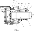
FIG. 4 is a top view of a vehicle driving device according to an embodiment of the present disclosure; -
FIG. 5 is a front view of a vehicle driving device according to an embodiment of the present disclosure; -
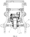
FIG. 6 is a schematic diagram of connection between a vehicle driving device and a frame according to an embodiment of the present disclosure; and -
FIG. 7 is a schematic diagram of cooperation between a vehicle driving device and a middle channel according to an embodiment of the present disclosure. - In the drawings:
1: first electric motor; 11: electric motor shaft of the first electric motor; 12: housing of the first electric motor; 2: second electric motor; 21: electric motor shaft of the second electric motor; 22: housing of the second electric motor; 3: electric motor controller; 31: housing of the electric motor controller; 4: oil pan; 5: engine; 6: variable-speed transmission structure; 61: first electric motor transmission gear set; 611: first electric motor first-stage gear; 612: engine second-stage gear; 62: second electric motor transmission gear set; 621: second electric motor driving gear; 622: second electric motor driven gear; 63: engine input gear set; 631: engine first-stage gear; 632: clutch input gear; 64: output gear set; 641: clutch output gear; 642: clutch driven gear; 643: differential input shaft; 65: clutch; 7: differential; 71: input bevel gear; 72: left output bevel gear; 73: right output bevel gear; 74: differential housing; 8: wheels; 9: variable-speed transmission structure housing; 10: left half shaft; 20: middle shaft; 30: right half shaft; 40: middle shaft tube; 50: oil-cooling plate heat exchanger; 60: frame; 70: first mount; 80: second mount; 90: middle channel; 901: accommodating cavity. - To make technical problems to be resolved in the present disclosure, technical solutions, and beneficial effects clearer, the following further describes the present disclosure in detail with reference to the accompanying drawings and embodiments. It should be understood that the specific embodiments described herein are merely used for explaining the present disclosure, but are not used for limiting the present disclosure.
- Referring to
FIG. 1 to FIG. 5 , a vehicle driving device provided in this embodiment of the present disclosure includes an electric motor assembly. The electric motor assembly includes a firstelectric motor 1, a secondelectric motor 2, and anelectric motor controller 3. Anelectric motor shaft 11 of the firstelectric motor 1 and anelectric motor shaft 21 of the secondelectric motor 2 extend in a length direction of a vehicle. The firstelectric motor 1 is arranged in front of the secondelectric motor 2. Theelectric motor controller 3 is fixed at tops of the firstelectric motor 1 and the secondelectric motor 2. The firstelectric motor 1 and the secondelectric motor 2 are electrically connected to theelectric motor controller 3 respectively. That is, theelectric motor controller 3 controls both the firstelectric motor 1 and the secondelectric motor 2, and there is no need to arrange two electric motor controllers, to help reduce costs. - In an embodiment, the first
electric motor 1 is an electric generator, and the secondelectric motor 2 is a driving electric motor. In other words, power of the secondelectric motor 2 is greater than power of the firstelectric motor 1. - In an embodiment, referring to
FIG. 3 , the vehicle driving device further includes anoil pan 4 connected to a bottom of the firstelectric motor 1. Theoil pan 4 is arranged below the firstelectric motor 1, so that theoil pan 4 can provide lubrication for structures such as the firstelectric motor 1, the secondelectric motor 2, and a variable-speed transmission structure 6 below, to ensure good lubrication performance on an urban road or a non-paved road. - In an embodiment, referring to
FIG. 3 , ahousing 22 of the secondelectric motor 2 is connected to a rear end surface of ahousing 12 of the firstelectric motor 1. Theelectric motor controller 3 is strip-shaped and extends in the length direction of the vehicle. Ahousing 31 of theelectric motor controller 3 is fixed at a top of thehousing 12 of the firstelectric motor 1 and a top of thehousing 22 of the secondelectric motor 2. - Specifically, referring to
FIG. 4 , thehousing 31 of theelectric motor controller 3 is fixed to thehousing 12 of the firstelectric motor 1 and thehousing 22 of the secondelectric motor 2 through a front left mounting point A1, a front right mounting point A2, a middle left mounting point A3, a middle right mounting point A4, a rear left mounting point A5, and a rear right mounting point A6. The front left mounting point A1 and the front right mounting point A2 are connected to thehousing 12 of the firstelectric motor 1, and the middle left mounting point A3, the middle right mounting point A4, the rear left mounting point A5, and the rear right mounting point A6 are connected to thehousing 21 of the secondelectric motor 2. In this way, theelectric motor controller 3 can be stably mounted at the tops of the firstelectric motor 1 and the secondelectric motor 2 through the six points. Specifically, connection brackets are respectively arranged on thehousing 31 of theelectric motor controller 3 at positions of the front left mounting point A1, the front right mounting point A2, the middle left mounting point A3, the middle right mounting point A4, the rear left mounting point A5, and the rear right mounting point A6. Nuts or threaded connection holes are correspondingly arranged on thehousing 12 of the firstelectric motor 1 and thehousing 22 of the secondelectric motor 2. The connection brackets are fixed to thehousing 12 of the firstelectric motor 1 and thehousing 22 of the secondelectric motor 2 by bolts. - In an embodiment, referring to
FIG. 1 , the vehicle driving device further includes anengine 5, the variable-speed transmission structure 6, and a differential 7. The variable-speed transmission structure 6 is arranged on a right side of the firstelectric motor 1. The variable-speed transmission structure 6 includes a first electric motor transmission gear set 61, a second electric motor transmission gear set 62, an engine input gear set 63, an output gear set 64, and a clutch 65. The engine input gear set 63 is connected between a first end of the clutch 65 and theengine 5. The output gear set 64 is connected between a second end of the clutch 65 and the differential 7. The first electric motor transmission gear set 61 is connected between the firstelectric motor 1 and the engine input gear set 63. The second electric motor transmission gear set 62 is connected between the secondelectric motor 2 and the output gear set 64. The differential 7 is connected towheels 8. In an embodiment, referring toFIG. 1 , the engine input gear set 63 includes an engine first-stage gear 631 and aclutch input gear 632 that mesh with each other. The engine first-stage gear 631 is connected to theengine 5, and theclutch input gear 632 is connected to the first end of the clutch 65. The first electric motor transmission gear set 61 includes a first electric motor first-stage gear 611 and an engine second-stage gear 612 that mesh with each other. The engine second-stage gear 612 meshes with the engine first-stage gear 631. Optionally, a flywheel is connected between theengine 5 and the engine first-stage gear 631. - In an embodiment, referring to
FIG. 1 , the output gear set 64 includes aclutch output gear 641, a clutch drivengear 642, and adifferential input shaft 643. Theclutch output gear 641 meshes with the clutch drivengear 642. The clutch drivengear 642 is connected to the differential 7 through thedifferential input shaft 643. Theclutch output gear 641 is connected to the second end of the clutch 65. The second electric motor transmission gear set 62 includes a second electricmotor driving gear 621 and a second electric motor drivengear 622 that mesh with each other. The second electric motor drivengear 622 and theclutch output gear 641 are coaxially connected to thedifferential input shaft 643. - In an engine direct driving mode, power of the
engine 5 is transferred to thewheels 8 through the engine input gear set 63, the clutch 65, the output gear set 64, and the differential 7. In comparison with the related art, one gear set is reduced, and transmission efficiency in the engine direct driving mode is improved. - The power of the
engine 5 passes through the engine first-stage gear 631, the engine second-stage gear 612, and the first electric motor first-stage gear 611, to drive the firstelectric motor 1 to generate electricity. The power of the secondelectric motor 2 passes through the second electricmotor driving gear 621, the second electric motor drivengear 622, thedifferential input shaft 643, and the differential 7, to drive thewheels 8 on left and right sides. Certainly, the power of theengine 5 may alternatively pass through the engine first-stage gear 631, theclutch input gear 632, the clutch 65, theclutch output gear 641, the clutch drivengear 642, thedifferential input shaft 643, and the differential 7, to drive thewheels 8 on left and right sides. - The vehicle driving device may have the engine direct driving mode, a pure-electric driving mode, and a hybrid driving mode. In the engine direct driving mode, the clutch 65 is engaged, and the power of the
engine 5 passes through the engine first-stage gear 631, theclutch input gear 632, the clutch 65, theclutch output gear 641, the clutch drivengear 642, thedifferential input shaft 643, and the differential 7, to drive thewheels 8 on left and right sides. In this case, the secondelectric motor 2 does not work, and the firstelectric motor 1 generates electricity or idles. In the pure-electric driving mode, the clutch 65 is separated, and the power of the secondelectric motor 2 passes through the second electricmotor driving gear 621, the second electric motor drivengear 622, thedifferential input shaft 643, and the differential 7, to drive thewheels 8 on left and right sides. In this case, theengine 5 does not work, or theengine 5 works and drives the firstelectric motor 1 to generate electricity. In the hybrid driving mode, the clutch 65 is engaged, the power of theengine 5 passes through the engine first-stage gear 631, theclutch input gear 632, the clutch 65, theclutch output gear 641, the clutch drivengear 642, thedifferential input shaft 643, and the differential 7, to drive thewheels 8 on left and right sides, and the power of the secondelectric motor 2 passes through the second electricmotor driving gear 621, the second electric motor drivengear 622, thedifferential input shaft 643, and the differential 7, to drive thewheels 8 on left and right sides. In this case, the firstelectric motor 1 generates electricity or idles. - In an embodiment, referring to
FIG. 2 andFIG. 5 , the differential 7 is arranged on a front lower right side of the firstelectric motor 1, to make full use of space between the electric motor assembly and theengine 5 at a front end or a steering machine at the front end, thereby reducing impact on a height of a crankshaft center of theengine 5. Thedifferential input shaft 643 is arranged on a lower right side of the firstelectric motor 1, to make full use of space between a frame and a vehicle body, so that sizes of the vehicle driving device in a middle channel in a Y-direction and a Z-direction are greatly reduced, and an arrangement requirement of theengine 5 is considered. - In an embodiment, referring to
FIG. 2 andFIG. 5 , the vehicle driving device further includes a variable-speedtransmission structure housing 9. The variable-speedtransmission structure housing 9 is fixed to a front end surface of ahousing 12 of the firstelectric motor 1. The first electric motor transmission gear set 61, the engine input gear set 63, the output gear set 64, and the clutch 65 are mounted inside the variable-speedtransmission structure housing 9. The second electric motor transmission gear set 62 is mounted inside thehousing 12 of the firstelectric motor 1. In this way, the firstelectric motor 1, the secondelectric motor 2, theelectric motor controller 3, and the variable-speed transmission structure are integrated together, and an integration level is higher. In addition, because the variable-speed transmission structure 6 is arranged on the right side of the firstelectric motor 1, the vehicle driving device is more compact in an X-direction (the length direction of the vehicle) and a Z-direction (the height direction of the vehicle ), so that middle channel space of the vehicle body is more compact, thereby reducing space occupation of the vehicle in the Z-direction and the X-direction, and helping improve human-machine performance of a driver and passive safety performance of the entire vehicle. - In an embodiment, referring to
FIG. 1 andFIG. 5 , the vehicle driving device further includes aleft half shaft 10, amiddle shaft 20, aright half shaft 30, and amiddle shaft tube 40 that is connected to a left side of the differential 7. The differential 7 includes aninput bevel gear 71, a leftoutput bevel gear 72, a rightoutput bevel gear 73, and adifferential housing 74. Theinput bevel gear 71, the leftoutput bevel gear 72, and the rightoutput bevel gear 73 are arranged inside thedifferential housing 74. Themiddle shaft 20 is connected between the leftoutput bevel gear 72 and theleft half shaft 10, theleft half shaft 10 is connected to aleft wheel 8, and theright half shaft 30 is connected between the rightoutput bevel gear 73 and aright wheel 8. Themiddle shaft 20 is rotatably arranged in themiddle shaft tube 40 through a bearing. Theleft half shaft 10 and theright half shaft 30 are generally symmetrical. Because the differential 7 is arranged on the lower right side of the firstelectric motor 1 and close to theright wheel 8, theright half shaft 30 is short. For symmetry, theleft half shaft 10 is also short. Therefore, themiddle shaft 20 is connected between theleft half shaft 10 and the leftoutput bevel gear 72, and themiddle shaft 20 is long. Therefore, themiddle shaft tube 40 is arranged to provide a fulcrum for themiddle shaft 20, thereby improving transmission stability. Themiddle shaft tube 40 is connected to the left side of the differential 7, to not only ensure that theleft half shaft 10 and theright half shaft 30 can be symmetrically arranged, but also improve the convenience of assembly and disassembly. - Certainly, in some other alternative embodiments, the
left half shaft 10 and themiddle shaft 20 may alternatively be combined into one shaft. In this case, themiddle shaft tube 40 may not be used. - In an embodiment, referring to
FIG. 1 , theelectric motor shaft 11 of the firstelectric motor 1 and theelectric motor shaft 21 of the secondelectric motor 2 are arranged spaced away in a width direction of the vehicle. That is, theelectric motor shaft 11 of the firstelectric motor 1 is not coaxial with theelectric motor shaft 21 of the secondelectric motor 2. In this way, space on the right side of the firstelectric motor 1 may be used to arrange the variable-speed transmission structure 6. - In an embodiment, the first
electric motor 1 and the secondelectric motor 2 are electrically connected to theelectric motor controller 3 respectively through copper bars. In this way, arrangement space and costs of a high-voltage wire harness are greatly saved, to facilitate light-weighting of the entire vehicle. Theelectric motor controller 3 is integrated at the tops of the firstelectric motor 1 and the secondelectric motor 2, to prevent multiple high-voltage wire harnesses from being arranged outside the structure, so that a risk that the high-voltage wire harness is squeezed and shorted out during a collision is reduced, thereby improving overall passive safety performance of a high-voltage system. - In an embodiment, a high-voltage direct-current bus interface of the
electric motor controller 3 is arranged on a right side of ahousing 31 of theelectric motor controller 3, and the high-voltage direct-current bus interface is connected to a battery pack through a wire harness. The battery pack is located on a rear side of theelectric motor controller 3. In comparison with arrangement of the high-voltage direct-current bus interface on a rear side of thehousing 31 of theelectric motor controller 3 in the related art, the high-voltage direct-current bus interface is arranged on the right side of thehousing 31 of theelectric motor controller 3, so that a size of theelectric motor controller 3 in the X-direction is reduced, energy absorption space of theelectric motor controller 3 in a head-on collision is enlarged, and a high-voltage safety factor of the entire vehicle is increased. - In an embodiment, referring to
FIG. 1 andFIG. 5 , the vehicle driving device further includes an oil-coolingplate heat exchanger 50. The oil-coolingplate heat exchanger 50 is arranged on a front left side of the firstelectric motor 1, to fully use space on the left side of the firstelectric motor 1. Therefore, not only an arrangement requirement is considered, but also cooling performance of the vehicle driving device is ensured. - In the vehicle driving device in this embodiment of the present disclosure, the
electric motor shaft 11 of the firstelectric motor 1 and theelectric motor shaft 21 of the secondelectric motor 2 extend in the length direction of the vehicle, the firstelectric motor 1 is arranged in front of the secondelectric motor 2, and theelectric motor controller 3 is fixed at the tops of the firstelectric motor 1 and the secondelectric motor 2. In this way, the electric motor assembly including the firstelectric motor 1, the secondelectric motor 2, and theelectric motor controller 3 has a high integration level, so that an integration level of the vehicle driving device can be improved, and an overall structure of the vehicle driving device is more compact. In addition, high-voltage wire flinging is avoided, to facilitate the light-weighting of the entire vehicle. In addition, both the firstelectric motor 1 and the secondelectric motor 2 are arranged longitudinally, so that a size of the vehicle driving device in the Y-direction is more compact. Because theelectric motor controller 3 is arranged at the tops of the two electric motors, and space of the vehicle in the Z-direction is fully used, the size of the vehicle driving device in the Y-direction is smaller. In this way, human-machine space of a driver and a co-driver in the entire vehicle can be improved, and the electric motor assembly is ergonomic while satisfying an ultra-large size required for power economy. - In addition, the vehicle driving device, carrying the
corresponding engine 5, can make full use of arrangement space of a front compartment in the X-direction, so that occupation of arrangement space of the vehicle in the Y-direction is reduced, and larger arrangement space is provided for a suspension system, to facilitate operational stability and smoothness of the entire vehicle. - The vehicle driving device is applicable to a front-wheel drive vehicle or a four-wheel drive vehicle (where a wheel-side drive axle may be added to a rear axle of the four-wheel drive vehicle). The vehicle driving device is applicable to new energy vehicle models such as an off-road vehicle, a pickup, and an SUV.
- In addition, referring to
FIG. 6 andFIG. 7 , an embodiment of the present disclosure further provides a vehicle, including aframe 60 and the foregoing vehicle driving device. The vehicle driving device is mounted on theframe 60. - In an embodiment, referring to
FIG. 6 , a lower left side of ahousing 22 of a secondelectric motor 2 is connected to theframe 60 through afirst mount 70, and a lower right side of thehousing 22 of the secondelectric motor 2 is connected to theframe 60 through asecond mount 80. In this way, a rear end of the vehicle driving device is connected to theframe 60 through thefirst mount 70 and thesecond mount 80. A front end of the vehicle driving device is indirectly mounted on theframe 60 through a front engine mount. Arrangement space for anengine 5 is reserved at the front end of the vehicle driving device, and different types ofengines 5 are mounted according to different vehicle models and different power requirements. The vehicle driving device is arranged longitudinally, to make full use of arrangement space of a front compartment in an X-direction, so that use of arrangement space in a Y-direction is reduced, and larger arrangement space is provided for a suspension system, to facilitate operational stability and smoothness of the entire vehicle. - In an embodiment, referring to
FIG. 7 , the vehicle has amiddle channel 90. Anaccommodating cavity 901 is provided on a front end of themiddle channel 90, and a rear side of the vehicle driving device extends into theaccommodating cavity 901. Specifically, the entire secondelectric motor 2, a rear part of a firstelectric motor 1, and a rear part of anelectric motor controller 3 are accommodated inside theaccommodating cavity 901, and a front part of theelectric motor controller 3, a front part of the firstelectric motor 1, a variable-speed transmission structure housing, and a differential 7 are located outside theaccommodating cavity 901. - The longitudinally arranged vehicle driving device is designed in cooperation with a contour of the
middle channel 90. Through internal structure optimization, modules are highly integrated, so that not only human-machine space and physical arrangement space of another system in the vehicle are ensured, but also functional implementation and process feasibility of the vehicle driving device are ensured. In addition, though a high integration level, high-voltage wire flinging is avoided, to facilitate light-weighting of the entire vehicle. - The foregoing descriptions are merely exemplary embodiments of the present disclosure, but are not intended to limit the present disclosure. Any modification, equivalent replacement, or improvement made within the spirit and principle of the present disclosure shall fall within the protection scope of the present disclosure.
Claims (16)
- A vehicle driving device, comprising an electric motor assembly, wherein the electric motor assembly comprises:a first electric motor (1);a second electric motor (2), an electric motor shaft (11) of the first electric motor (1) and an electric motor shaft (21) of the second electric motor (2) extending in a length direction of a vehicle, and the first electric motor (1) being arranged in front of the second electric motor (2); andan electric motor controller (3), fixed at tops of the first electric motor (1) and the second electric motor (2), the first electric motor (1) and the second electric motor (2) being electrically connected to the electric motor controller (3) respectively.
- The vehicle driving device according to claim 1, further comprising an oil pan (4) connected to a bottom of the first electric motor (1).
- The vehicle driving device according to claim 1, wherein a housing (22) of the second electric motor (2) is connected to a rear end surface of a housing (12) of the first electric motor (1); and
the electric motor controller (3) is strip-shaped and extends in the length direction of the vehicle, and a housing (31) of the electric motor controller (3) is fixed at a top of the housing (12) of the first electric motor (1) and a top of the housing (22) of the second electric motor (2). - The vehicle driving device according to claim 1, further comprising an engine (5), a variable-speed transmission structure (6), and a differential (7), the variable-speed transmission structure (6) being arranged on a right side of the first electric motor (1); and
the variable-speed transmission structure (6) comprising a first electric motor transmission gear set (61), a second electric motor transmission gear set (62), an engine input gear set (63), an output gear set (64), and a clutch (65), the engine input gear set (63) being connected between a first end of the clutch (65) and the engine (5), the output gear set (64) being connected between a second end of the clutch (65) and the differential (7), the first electric motor transmission gear set (61) being connected between the first electric motor (1) and the engine input gear set (63), the second electric motor transmission gear set (62) being connected between the second electric motor (2) and the output gear set (64), and the differential (7) being connected to wheels (8). - The vehicle driving device according to claim 4, wherein the engine input gear set (63) comprises an engine first-stage gear (631) and a clutch input gear (632) that mesh with each other, the engine first-stage gear (631) being connected to the engine (5), and the clutch input gear (632) being connected to the first end of the clutch (65); and
the first electric motor transmission gear set (61) comprises a first electric motor first-stage gear (611) and an engine second-stage gear (612) that mesh with each other, the engine second-stage gear (612) meshing with the engine first-stage gear (631). - The vehicle driving device according to claim 4, wherein the output gear set (64) comprises a clutch output gear (641), a clutch driven gear (642), and a differential input shaft (643), the clutch output gear (641) meshing with the clutch driven gear (642), the clutch driven gear (642) being connected to the differential (7) through the differential input shaft (643), and the clutch output gear (641) being connected to the second end of the clutch (65); and
the second electric motor transmission gear set (62) comprises a second electric motor driving gear (621) and a second electric motor driven gear (622) that mesh with each other, the second electric motor driven gear (622) and the clutch output gear (641) being coaxially connected to the differential input shaft (643). - The vehicle driving device according to claim 6, wherein the differential (7) is arranged on a front lower right side of the first electric motor (1), and the differential input shaft (643) is arranged on a lower right side of the first electric motor (1).
- The vehicle driving device according to claim 4, further comprising a variable-speed transmission structure housing (9), the variable-speed transmission structure housing (9) being fixed to a front end surface of a housing (12) of the first electric motor 1, the first electric motor transmission gear set (61), the engine input gear set (63), the output gear set (64), and the clutch (65) being mounted inside the variable-speed transmission structure housing (9), and the second electric motor transmission gear set (62) being mounted inside the housing (12) of the first electric motor (1).
- The vehicle driving device according to claim 4, further comprising a left half shaft (10), a middle shaft (20), a right half shaft (30), and a middle shaft tube (40) that is connected to a left side of the differential (7), the differential (7) comprises an input bevel gear (71), a left output bevel gear (72), and a right output bevel gear (73), the middle shaft (20) is connected between the left output bevel gear (72) and the left half shaft (10), the left half shaft (10) is connected to a left wheel, and the right half shaft (30) is connected between the right output bevel gear (73) and a right wheel; and
the middle shaft (20) is rotatably arranged in the middle shaft tube (40). - The vehicle driving device according to claim 1, wherein the electric motor shaft (11) of the first electric motor (1) and the electric motor shaft (21) of the second electric motor (2) are arranged spaced away in a width direction of the vehicle.
- The vehicle driving device according to claim 1, wherein the first electric motor (1) and the second electric motor (2) are electrically connected to the electric motor controller (3) respectively through copper bars.
- The vehicle driving device according to claim 1, wherein a high-voltage direct-current bus interface of the electric motor controller (3) is arranged on a right side of a housing (31) of the electric motor controller (3), and the high-voltage direct-current bus interface is connected to a battery pack through a wire harness.
- The vehicle driving device according to claim 1, further comprising an oil-cooling plate heat exchanger (50), the oil-cooling plate heat exchanger (50) being arranged on a front left side of the first electric motor (1).
- A vehicle, comprising a frame (60) and the vehicle driving device according to any one of claims 1 to 13, the vehicle driving device being mounted on the frame (60).
- The vehicle according to claim 14, wherein a lower left side of a housing (22) of a second electric motor (2) is connected to the frame (60) through a first mount (70), and a lower right side of the housing (22) of the second electric motor (2) is connected to the frame (60) through a second mount (80).
- The vehicle according to claim 14, comprising a middle channel (90), an accommodating cavity (901) being provided on a front end of the middle channel (90), and a rear side of the vehicle driving device extending into the accommodating cavity (901).
Applications Claiming Priority (2)
| Application Number | Priority Date | Filing Date | Title |
|---|---|---|---|
| CN202221963231.9U CN218228632U (en) | 2022-07-27 | 2022-07-27 | Vehicle drive device and vehicle |
| PCT/CN2023/090736 WO2024021716A1 (en) | 2022-07-27 | 2023-04-26 | Vehicle driving device and vehicle |
Publications (2)
| Publication Number | Publication Date |
|---|---|
| EP4549208A1 true EP4549208A1 (en) | 2025-05-07 |
| EP4549208A4 EP4549208A4 (en) | 2025-10-29 |
Family
ID=84678288
Family Applications (1)
| Application Number | Title | Priority Date | Filing Date |
|---|---|---|---|
| EP23844931.8A Pending EP4549208A4 (en) | 2022-07-27 | 2023-04-26 | VEHICLE DRIVE UNIT AND VEHICLE |
Country Status (6)
| Country | Link |
|---|---|
| US (1) | US12623529B2 (en) |
| EP (1) | EP4549208A4 (en) |
| CN (1) | CN218228632U (en) |
| AU (1) | AU2023312509A1 (en) |
| MX (1) | MX2025000911A (en) |
| WO (1) | WO2024021716A1 (en) |
Families Citing this family (6)
| Publication number | Priority date | Publication date | Assignee | Title |
|---|---|---|---|---|
| CN218228632U (en) * | 2022-07-27 | 2023-01-06 | 比亚迪股份有限公司 | Vehicle drive device and vehicle |
| CN118636650A (en) * | 2024-06-06 | 2024-09-13 | 中国第一汽车股份有限公司 | Longitudinal multi-speed dual-motor hybrid system and hybrid power driving method |
| CN118494163A (en) * | 2024-06-13 | 2024-08-16 | 麦格纳动力总成(江西)有限公司 | Longitudinally-arranged precursor double-motor hybrid power structure |
| CN222987964U (en) * | 2024-08-30 | 2025-06-17 | 比亚迪股份有限公司 | Driving assembly, power system and vehicle |
| CN119078962A (en) * | 2024-09-12 | 2024-12-06 | 上汽通用五菱汽车股份有限公司 | vehicle |
| CN121246525B (en) * | 2025-12-08 | 2026-03-13 | 中国第一汽车股份有限公司 | Longitudinal hybrid system and its vehicle |
Family Cites Families (26)
| Publication number | Priority date | Publication date | Assignee | Title |
|---|---|---|---|---|
| DE10248715A1 (en) * | 2002-10-18 | 2004-05-13 | Compact Dynamics Gmbh | Hybrid drive for a motor vehicle |
| CN1291855C (en) * | 2002-12-08 | 2006-12-27 | 中国第一汽车集团公司 | Dual-motor hybrid vehicle powertrain |
| JP4201282B2 (en) * | 2006-03-23 | 2008-12-24 | トヨタ自動車株式会社 | Vehicle drive device |
| US8504259B2 (en) * | 2007-11-04 | 2013-08-06 | GM Global Technology Operations LLC | Method for determining inertia effects for a hybrid powertrain system |
| JP5541976B2 (en) | 2010-06-18 | 2014-07-09 | 富士重工業株式会社 | Drive device for hybrid vehicle |
| DE102013223409A1 (en) * | 2013-11-15 | 2015-05-21 | Mtu Friedrichshafen Gmbh | Electro-mechanical hybrid drive and vehicle |
| JP2017019319A (en) * | 2015-07-08 | 2017-01-26 | Ntn株式会社 | Vehicle driving device with two motors |
| CN205059227U (en) | 2015-10-27 | 2016-03-02 | 上海中科深江电动车辆有限公司 | Motor is indulged and is put formula hybrid power system |
| CN105216653A (en) * | 2015-10-30 | 2016-01-06 | 福建万润新能源科技有限公司 | A kind of double-motor multi-mode power system of adjustable speed and driving method |
| CN110177960B (en) * | 2016-12-22 | 2022-10-25 | 伊顿康明斯自动传输技术有限责任公司 | High-efficiency high-output transmission |
| CN106808989A (en) * | 2017-03-03 | 2017-06-09 | 中国第汽车股份有限公司 | A kind of pure electric vehicle double-motor driving device |
| JP6830053B2 (en) * | 2017-12-05 | 2021-02-17 | 株式会社豊田中央研究所 | Series hybrid car |
| CN213892154U (en) * | 2018-04-06 | 2021-08-06 | 日本电产株式会社 | motor unit |
| CN109177716B (en) * | 2018-08-17 | 2019-11-26 | 宁波上中下自动变速器有限公司 | Dynamical system for hybrid vehicle |
| CN209159400U (en) * | 2018-10-31 | 2019-07-26 | 比亚迪股份有限公司 | Hybrid drive systems and vehicles |
| CN209627156U (en) * | 2019-05-22 | 2019-11-12 | 苏州达思灵电机有限公司 | A kind of shared cooling water channel of motor and controller |
| CN114025979B (en) * | 2019-06-26 | 2024-06-07 | 日产自动车株式会社 | Driving device for vehicle |
| JP2021164365A (en) | 2020-04-02 | 2021-10-11 | 株式会社Subaru | Vehicular control device |
| WO2022032520A1 (en) * | 2020-08-12 | 2022-02-17 | 蔚然(南京)动力科技有限公司 | Coaxial asynchronous electric drive system |
| CN112590530A (en) * | 2020-12-04 | 2021-04-02 | 浙江吉利控股集团有限公司 | Dual-motor hybrid power driving device and vehicle with same |
| CN213920648U (en) | 2020-12-09 | 2021-08-10 | 北京车和家信息技术有限公司 | Integrated form electric drive system and vehicle |
| CN216805098U (en) * | 2021-09-03 | 2022-06-24 | 上海汽车变速器有限公司 | Double-motor driving system for new energy automobile |
| CN114211949B (en) * | 2022-02-08 | 2024-07-09 | 浙江吉利控股集团有限公司 | Hybrid transmission system and vehicle |
| CN115306885A (en) * | 2022-07-19 | 2022-11-08 | 东风汽车集团股份有限公司 | Intermediate plate, shell assembly, hybrid electric drive system and hybrid vehicle |
| CN218228632U (en) * | 2022-07-27 | 2023-01-06 | 比亚迪股份有限公司 | Vehicle drive device and vehicle |
| CN116061676A (en) * | 2023-01-03 | 2023-05-05 | 重庆长安汽车股份有限公司 | Double-motor hybrid transmission device and automobile |
-
2022
- 2022-07-27 CN CN202221963231.9U patent/CN218228632U/en active Active
-
2023
- 2023-04-26 WO PCT/CN2023/090736 patent/WO2024021716A1/en not_active Ceased
- 2023-04-26 EP EP23844931.8A patent/EP4549208A4/en active Pending
- 2023-04-26 AU AU2023312509A patent/AU2023312509A1/en active Pending
-
2025
- 2025-01-21 US US19/033,319 patent/US12623529B2/en active Active
- 2025-01-22 MX MX2025000911A patent/MX2025000911A/en unknown
Also Published As
| Publication number | Publication date |
|---|---|
| MX2025000911A (en) | 2025-03-07 |
| US12623529B2 (en) | 2026-05-12 |
| EP4549208A4 (en) | 2025-10-29 |
| AU2023312509A1 (en) | 2025-02-06 |
| WO2024021716A1 (en) | 2024-02-01 |
| CN218228632U (en) | 2023-01-06 |
| US20250162401A1 (en) | 2025-05-22 |
Similar Documents
| Publication | Publication Date | Title |
|---|---|---|
| US12623529B2 (en) | Vehicle driving device and vehicle | |
| EP3138718B1 (en) | Integrated steering drive axle for vehicle and electric vehicle | |
| EP2873544A1 (en) | Electric vehicle | |
| CN209813696U (en) | Vehicle and electric drive power assembly thereof | |
| CN202080105U (en) | Driving equipment for electric vehicle | |
| KR20120137291A (en) | Motor vehicle having a drive train which has a laterally arranged internal combustion engine | |
| CN210337544U (en) | Integrated coaxial electric drive axle system | |
| CN109435657A (en) | A kind of three-in-one electric drive vehicle bridge and its control method for electric vehicle | |
| CN107856477A (en) | New energy semitrailer process auxiliary drive back axle and its energy back-feed control method | |
| CN112319204A (en) | Vehicle hybrid system and vehicle control method | |
| WO2020240736A1 (en) | Hybrid electric vehicle | |
| CN220594620U (en) | Oil-cooled double-motor driving system of electric automobile | |
| CN111098924B (en) | A special chassis and control method for an all-wheel drive hybrid electric vehicle without an intermediate transmission shaft | |
| CN115056645A (en) | Plug-in hybrid power pickup | |
| CN212637144U (en) | Motor drive assembly and electric automobile | |
| CN1757534A (en) | Electric vehicle driven by combination of oil-full engine and parallel electric motors | |
| CN214928732U (en) | Electric drive axle, electric drive system and electric vehicle | |
| CN114379354B (en) | Vehicle with a vehicle body having a vehicle body support | |
| CN214775203U (en) | Electric drive axle mechanism and electric drive chassis comprising same | |
| EP3118045B1 (en) | Electric vehicle | |
| CN211468576U (en) | A special chassis for an all-wheel drive hybrid vehicle without an intermediate transmission shaft | |
| CN204659477U (en) | A kind of integrated components and parts for the pure electronic logistic car of high continual mileage | |
| CN210733715U (en) | Two-stage speed reduction electric drive axle with double motors and single-speed parallel shaft output | |
| CN115214330A (en) | Motor vertical power system and automobile | |
| CN222727800U (en) | Range-extending power assembly and vehicle |
Legal Events
| Date | Code | Title | Description |
|---|---|---|---|
| STAA | Information on the status of an ep patent application or granted ep patent |
Free format text: STATUS: THE INTERNATIONAL PUBLICATION HAS BEEN MADE |
|
| PUAI | Public reference made under article 153(3) epc to a published international application that has entered the european phase |
Free format text: ORIGINAL CODE: 0009012 |
|
| STAA | Information on the status of an ep patent application or granted ep patent |
Free format text: STATUS: REQUEST FOR EXAMINATION WAS MADE |
|
| 17P | Request for examination filed |
Effective date: 20250203 |
|
| AK | Designated contracting states |
Kind code of ref document: A1 Designated state(s): AL AT BE BG CH CY CZ DE DK EE ES FI FR GB GR HR HU IE IS IT LI LT LU LV MC ME MK MT NL NO PL PT RO RS SE SI SK SM TR |
|
| A4 | Supplementary search report drawn up and despatched |
Effective date: 20251001 |
|
| RIC1 | Information provided on ipc code assigned before grant |
Ipc: B60K 6/26 20071001AFI20250925BHEP Ipc: B60K 6/40 20071001ALI20250925BHEP Ipc: B60K 6/547 20071001ALI20250925BHEP Ipc: B60K 1/02 20060101ALI20250925BHEP Ipc: B60K 5/02 20060101ALI20250925BHEP Ipc: B60K 6/387 20071001ALI20250925BHEP Ipc: B60K 6/405 20071001ALI20250925BHEP Ipc: B60K 6/442 20071001ALI20250925BHEP |
|
| DAV | Request for validation of the european patent (deleted) | ||
| DAX | Request for extension of the european patent (deleted) |