EP4549184A1 - Work machine - Google Patents
Work machine Download PDFInfo
- Publication number
- EP4549184A1 EP4549184A1 EP23831147.6A EP23831147A EP4549184A1 EP 4549184 A1 EP4549184 A1 EP 4549184A1 EP 23831147 A EP23831147 A EP 23831147A EP 4549184 A1 EP4549184 A1 EP 4549184A1
- Authority
- EP
- European Patent Office
- Prior art keywords
- duct
- air
- operator
- conditioner body
- air conditioner
- Prior art date
- Legal status (The legal status is an assumption and is not a legal conclusion. Google has not performed a legal analysis and makes no representation as to the accuracy of the status listed.)
- Pending
Links
Images











Classifications
-
- E—FIXED CONSTRUCTIONS
- E02—HYDRAULIC ENGINEERING; FOUNDATIONS; SOIL SHIFTING
- E02F—DREDGING; SOIL-SHIFTING
- E02F9/00—Component parts of dredgers or soil-shifting machines, not restricted to one of the kinds covered by groups E02F3/00 - E02F7/00
- E02F9/08—Superstructures; Supports for superstructures
- E02F9/0858—Arrangement of component parts installed on superstructures not otherwise provided for, e.g. electric components, fenders, air-conditioning units
-
- B—PERFORMING OPERATIONS; TRANSPORTING
- B60—VEHICLES IN GENERAL
- B60H—ARRANGEMENTS OF HEATING, COOLING, VENTILATING OR OTHER AIR-TREATING DEVICES SPECIALLY ADAPTED FOR PASSENGER OR GOODS SPACES OF VEHICLES
- B60H1/00—Heating, cooling or ventilating devices
-
- B—PERFORMING OPERATIONS; TRANSPORTING
- B60—VEHICLES IN GENERAL
- B60H—ARRANGEMENTS OF HEATING, COOLING, VENTILATING OR OTHER AIR-TREATING DEVICES SPECIALLY ADAPTED FOR PASSENGER OR GOODS SPACES OF VEHICLES
- B60H1/00—Heating, cooling or ventilating devices
- B60H1/32—Cooling devices
-
- B—PERFORMING OPERATIONS; TRANSPORTING
- B60—VEHICLES IN GENERAL
- B60H—ARRANGEMENTS OF HEATING, COOLING, VENTILATING OR OTHER AIR-TREATING DEVICES SPECIALLY ADAPTED FOR PASSENGER OR GOODS SPACES OF VEHICLES
- B60H3/00—Other air-treating devices
- B60H3/06—Filtering
-
- E—FIXED CONSTRUCTIONS
- E02—HYDRAULIC ENGINEERING; FOUNDATIONS; SOIL SHIFTING
- E02F—DREDGING; SOIL-SHIFTING
- E02F9/00—Component parts of dredgers or soil-shifting machines, not restricted to one of the kinds covered by groups E02F3/00 - E02F7/00
- E02F9/16—Cabins, platforms, or the like, for drivers
-
- F—MECHANICAL ENGINEERING; LIGHTING; HEATING; WEAPONS; BLASTING
- F24—HEATING; RANGES; VENTILATING
- F24F—AIR-CONDITIONING; AIR-HUMIDIFICATION; VENTILATION; USE OF AIR CURRENTS FOR SCREENING
- F24F13/00—Details common to, or for air-conditioning, air-humidification, ventilation or use of air currents for screening
- F24F13/02—Ducting arrangements
Definitions
- the present invention relates to a working machine such as a backhoe.
- Patent Literature 1 includes a duct to guide and send conditioned air from an air conditioner body into a cabin.
- the duct includes a plurality of ducts connected together, and includes a plurality of air outlets inside the cabin.
- Patent Literature 1 includes a duct to guide and send conditioned air from an air conditioner body into a cabin.
- the duct includes a plurality of ducts connected together.
- the working machine disclosed in Patent Literature 2 includes a cabin, and an air conditioner body to generate conditioned air to be supplied into the cabin.
- the cabin is provided, at the left side surface thereof, with an outside air inlet to allow outside air to be supplied to the air conditioner body (see FIG. 1 and paragraph 0178).
- an air-mixing air conditioner body to generate conditioned air by mixing cool air and warm air may be used.
- conditioned air in which cool air and warm air are not thoroughly mixed may be discharged from the air conditioner body, pass through the ducts, and be ejected through air outlet(s).
- streams of conditioned air having different temperatures are blown out via a plurality of air outlets.
- Patent Literature 1 there may be cases in which, when a second duct is inserted and connected to a first duct, or when the second duct is detached from the first duct, the cushioning comes off because of the inner surface of a duct rubbing against the outer surface of the cushioning.
- the present invention was made in view of the above-described problems, and an object thereof is to provide a working machine which makes it possible to eject, through air outlet(s) of duct(s), conditioned air at a suitable temperature generated by the air conditioner body by thoroughly mixing warm air and cool air.
- Another object of the present invention is to make it possible, in a working machine including a duct structure including a plurality of connected ducts, to eliminate or reduce the likelihood that cushioning provided between the ducts will come off when the ducts are attached or detached to or from each other.
- Another object of the present invention is to provide a work machine in which a large space is available for a filter to remove foreign matter from air introduced through an outside air inlet, and which thereby allows a large filter to be placed in the space.
- a working machine includes a machine body, a cabin on the machine body, an operator's seat provided inside the cabin, an air conditioner body to generate conditioned air to be supplied into the cabin, and a duct structure to guide conditioned air supplied from the air conditioner body, wherein the air conditioner body is operable to mix cool air and warm air to generate conditioned air for cooling or heating, the duct structure includes a first duct to allow conditioned air for cooling to flow therethrough, a second duct to allow conditioned air for heating to flow therethrough, a switching box connected to the first duct and the second duct and including a switch portion to switch between a first state in which conditioned air supplied from the air conditioner body is allowed to flow through the first duct, and a second state in which conditioned air supplied from the air conditioner body is allowed to flow through the second duct, and a relay duct to connect the air conditioner body and the switching box to guide conditioned air generated by the air conditioner body to the switching box.
- the air conditioner body may be located rearward of the operator's seat.
- the duct structure may extend from a position rearward of the operator's seat, via a space at one side of the operator's seat, to a position forward of the operator's seat.
- the working machine may further include a manipulator provided at one side of the operator's seat.
- the first duct may extend between the manipulator and an inner wall surface of the cabin that faces the manipulator.
- the first duct may include a first air outlet.
- the first air outlet may include a front air outlet which includes an opening located at the one side of the operator's seat and higher than the manipulator.
- the first air outlet may include a rear air outlet which includes an opening located rearward of the operator's seat.
- the switching box may be provided at the one side of the operator's seat.
- the duct structure may extend through a space below the manipulator in a front-rear direction.
- the first duct may include a flat portion which is shorter in a machine body width direction than in a front-rear direction.
- the flat portion may be provided between the manipulator and the inner wall surface of the cabin.
- the flat portion may include a front air outlet at a front portion thereof, and includes a rear air outlet at a rear portion thereof.
- the first duct may include a main portion to connect the switching box and a third duct provided forward of the first duct, and the flat portion extending upward from the main portion along the inner wall surface of the cabin.
- the flat portion may be shorter than the main portion in the machine body width direction.
- the relay duct may include a passage enlarged portion in which a cross-sectional area of a passage thereof increases in a direction from the air conditioner body toward the switching box.
- a working machine includes a machine body, a cabin on the machine body, an air conditioner body to generate conditioned air to be supplied into the cabin, and a duct structure to guide conditioned air supplied from the air conditioner body, wherein the duct structure includes one duct and another duct connected together, the one duct includes a first connector portion to be inserted into and connected to the another duct, the another duct includes a second connector portion to receive and to be connected to the one duct, the first connector portion includes a first end surface perpendicular to a direction in which the first connector portion is inserted, the second connector portion includes a second end surface to face the first end surface, and cushioning is interposed between the first end surface and the second end surface.
- the first end surface may be an annular surface extending inward from an outer peripheral surface of the one duct.
- the second end surface may be an annular surface extending inward from an outer peripheral surface of the another duct.
- the cushioning may be an annular component to abut the first end surface and the second end surface
- the second connector portion may include a folded portion folded from a radially innermost portion of the second end surface in a direction away from the first end surface.
- the first connector portion may include a tubular portion extending from a radially innermost portion of the first end surface toward the another duct.
- the tubular portion may be provided, on an outer surface thereof, with a projection to engage with the folded portion.
- the folded portion may be configured to abut the outer surface of the tubular portion when the one duct and the another duct are connected to each other.
- the cushioning may be configured to abut the first end surface, the second end surface, and the outer surface of the tubular portion when the one duct and the another duct are connected to each other
- the cushioning may be bonded to the first end surface or the second end surface.
- a working machine includes a machine body, a cabin on the machine body, an operator's seat provided inside the cabin, and an air conditioner body to generate conditioned air to be supplied into the cabin, wherein the cabin includes, at a back surface thereof, an outside air inlet to allow outside air to be introduced therethrough into the air conditioner body.
- the air conditioner body may be provided rearward of the operator's seat.
- the back surface of the cabin may have attached thereto a rear cover projecting rearward from the back surface.
- the outside air inlet may be provided in the rear cover.
- the rear cover may include a lid closeable and openable.
- the outside air inlet may be provided in the lid.
- the working machine may further include a first filter to remove foreign matter contained in outside air introduced through the outside air inlet, an outside air duct to guide outside air that has passed through the first filter toward the air conditioner body.
- the first filter may be attached to the outside air duct.
- the working machine may further include a second filter coarser than the first filter and provided between the outside air inlet and the first filter, and a frame to fix the second filter and the first filter to the outside air duct.
- the working machine may further include an insect catching net provided between the outside air inlet and the second filter.
- the lid may have, attached to a front portion thereof, a case to house the net such that the net is removable.
- the case may include a front panel provided forward of the net such that the front panel faces the outside air inlet.
- the front panel may include an opening to allow passage of outside air taken in through the outside air inlet. The opening may be located higher than the outside air inlet.
- the case may include a projecting portion projecting from the front panel toward the outside air inlet and configured to abut a front surface of the net.
- the extent to which the projecting portion projects may increase in a top-to-bottom direction.
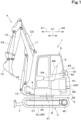
- FIG. 1 is a side view schematically illustrating a general configuration of a working machine 1 according to the present embodiment.
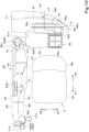
- FIG. 2 is a plan view schematically illustrating the working machine 1.
- a backhoe which is a swivel working machine, is discussed as an example of the working machine 1.
- the working machine 1 includes a machine body (swivel base) 2, a traveling device 3, and a working device 4. Note that the working device 4 is not illustrated in FIG. 2 .
- a cabin 5 is mounted on the machine body 2.
- the cabin 5 contains therein (in the interior thereof) an operator's seat 6 for the operator (user) to sit. That is, the operator's seat 6 is surrounded by the cabin 5.
- the operator's seat 6 includes a seat 6A where the operator sits, and a backrest 6B to receive the back of the operator.
- the direction in which the operator seated on the operator's seat 6 of the working machine 1 faces is referred to as a forward direction (front)
- the rearward direction from the operator is referred to as a rearward direction (rear)
- a direction of arrow K1 in FIGS. 1 and 2 is referred to as a front-rear direction.
- the leftward direction from the operator is referred to as a leftward direction (left)
- the rightward direction from the operator far side in FIG 1 , direction of arrow B2 in FIG. 2
- the horizontal direction perpendicular to the front-rear direction K1 is referred to as a machine body width direction K2 (see FIG. 2 ).
- the traveling device 3 is a crawler type traveling device to support the machine body 2 such that the machine body 2 is allowed to travel.
- the traveling device 3 includes a travel frame 3A, a first traveling device 3L provided on the left side of the travel frame 3A, and a second traveling device 3R provided on the right side of the travel frame 3A.
- the first traveling device 3L and the second traveling device 3R are each driven by a travel motor M1 including a hydraulic motor (hydraulic actuator).
- the crawler type traveling device 3 is used in the present embodiment, but this does not imply any limitation.
- a wheeled traveling device or the like may be used.
- a dozer device 7 is attached on the front portion of the traveling device 3 (see FIG. 1 ).
- the machine body 2 is supported via a swivel bearing 8 on the traveling device 3 such that the machine body 2 is rotatable about a swivel axis X1 which is an axis extending in the up-and-down direction.
- the cabin 5 is mounted at a front left portion of the machine body 2.
- the machine body 2 includes, at a front portion thereof, a support bracket 9 and a swing bracket 10 to support the working device 4.
- the support bracket 9 projects forward from the machine body 2.
- the swing bracket 10 is attached to the front portion of the support bracket 9 such that the swing bracket 10 is swingable about a vertical axis (axis extending in the up-and-down direction).
- the working device 4 includes a boom 11, an arm 12 and a bucket 13.
- the proximal portion of the boom 11 is pivotally attached to an upper portion of the swing bracket 10 to be rotatable about a lateral axis (axis extending in the machine body width direction K2).
- the arm 12 is pivotally attached to a distal portion of the boom 11 to be rotatable about a lateral axis.
- the bucket 13 is provided on a distal portion of the arm 12 to be able to shovel and dump.
- the working machine 1 is configured to have attached thereto some other working tool (hydraulic attachment) that can be driven by a hydraulic actuator, in addition to or instead of the bucket 13.
- working tool include hydraulic breakers, hydraulic crushers, angle brooms, earth augers, pallet forks, sweepers, mowers, and snow blowers.
- the swing bracket 10 is swingable via the extension and retraction of a swing cylinder C1.
- the boom 11 is swingable by the extension and retraction of a boom cylinder C2.
- the arm 12 is swingable by the extension and retraction of an arm cylinder C3.
- the bucket 13 can shovel or dump by the extension and retraction of a bucket cylinder C4.
- the swing cylinder C1, the boom cylinder C2, the arm cylinder C3, and the bucket cylinder C4 each include a hydraulic cylinder (hydraulic actuator).
- a prime mover E1 is mounted on a rear portion of the machine body 2.
- the prime mover E1 is a diesel engine.
- the prime mover E1 may be a gasoline engine or an electric motor, or may be a hybrid prime mover that includes an engine and an electric motor.
- the prime mover E1 has a cooling fan 14 attached to a right portion thereof. The cooling fan 14 is driven by the prime mover E1 to generate cooling air flowing from the right to the left, i.e., from the outside of the machine body 2 toward the prime mover E1.
- a radiator 15, an oil cooler 16 and a fuel cooler 17 are provided on the right of the cooling fan 14.
- the radiator 15 is a cooler to cool coolant that cools the prime mover E1.
- the oil cooler 16 is a cooler to cool return hydraulic fluid returning from hydraulic actuators such as hydraulic cylinder(s) and/or hydraulic motor(s).
- the fuel cooler 17 is a cooler to cool fuel. The coolers are cooled by cooling air drawn in by the cooling fan 14.
- a compressor 18 driven by the prime mover E1 is provided forward of a right portion of the prime mover E1.
- the compressor 18 is a device included in an air conditioning system (air conditioner) of the working machine 1, and compresses coolant (air conditioning gas) into semi-liquid.
- a fuel tank 19 is provided in front of the compressor 18, the radiator 15 and the oil cooler 16.
- the fuel tank 19 is a tank to store fuel for the prime mover E1.
- a battery 22 is provided in front of the fuel tank 19.
- the battery 22 is a storage battery to supply electricity to electric component(s) in or on the working machine 1.
- a condenser 23 and a receiver 24, which are included in the air conditioning system, are provided in front of the battery 22.
- the condenser 23 is a device to dissipate heat of the coolant from the compressor 18 to liquefy the coolant.
- the condenser 23 is a cooler to cool the semi-liquid coolant obtained by the compressor 18 to promote the liquefaction.
- the condenser 23 is an electric condenser cooled by an electric fan.
- the receiver 24 is a device to store the coolant liquefied by the condenser 23, and to separate the liquefied coolant from the coolant not liquefied by the condenser 23 and to remove moisture and impurities.
- a hydraulic pump 25 is attached to one of opposite ends (left portion) of the prime mover E1.
- the hydraulic pump 25 is driven by power from the prime mover E1.
- the hydraulic pump 25 delivers hydraulic fluid (pressure oil) to drive hydraulic actuators such as hydraulic motor(s) and/or hydraulic cylinder(s) in or on the working machine 1.
- a hydraulic fluid tank 28 is provided on the left of the prime mover E1.
- the hydraulic fluid tank 28 is a tank to store hydraulic fluid.
- the hydraulic fluid tank 28 is provided lower than the operator's seat 6. Hydraulic fluid is supplied from the hydraulic fluid tank 28 to the hydraulic pump 25.
- a control valve V1 is provided in front of the hydraulic fluid tank 28.
- the control valve V1 controls the flow rate of hydraulic fluid supplied from the hydraulic pump 25 to hydraulic actuator(s) in or on the working machine 1 driven by the hydraulic fluid.
- the control valve V1 is a valve unit including a group of control valves to control the flow rate of hydraulic fluid supplied to the hydraulic actuators in or on the working machine 1.
- a left manipulator 20 and a right manipulator 21 are provided on opposite sides of the operator's seat 6.
- the left manipulator 20 is provided at the left of the operator's seat 6.
- the right manipulator 21 is provided at the right of the operator's seat 6.
- the right manipulator 21 includes a right operating lever 26 and a dozer operating lever 27. It is possible to control valve(s) for the boom cylinder C2 and the bucket cylinder C4 by operating the right operating lever 26. It is possible to control control valve(s) for the dozer cylinder by operating the dozer operating lever 27.
- the right manipulator 21 is a manipulator to output electric signals according to the operation of the right operating lever 26 or the dozer operating lever 27.
- the right operating lever 26 is a joystick lever pivotable forward, rearward, leftward and rightward.
- the dozer operating lever 27 is a lever pivotable rearward and forward.
- the right manipulator 21 includes a first detector 32 (see FIG. 11 ) to detect the operation amount and the operation direction of the right operating lever 26, and a second detector (not illustrated) to detect the operation amount and the operation direction of the dozer operating lever 27.
- the first detector 32 outputs an electric signal to control control valve(s) (solenoid valve(s)) for the boom cylinder C2 and the bucket cylinder C4 according to the operation amount and the operation direction of the right operating lever 26.
- the second detector outputs an electric signal to control control valve(s) (solenoid valve(s)) for the dozer cylinder according to the operation amount and the operation direction of the dozer operating lever 27.
- the left manipulator 20 includes a left operating lever 30 and an unloading lever 31. It is possible to control control valve(s) for swiveling and arm operation by operating the left operating lever 30. It is possible to switch hydraulic actuator(s) of the working machine 1 between an operation-enabled state and an operation-disabled state by operating the unloading lever 31.
- a display 33 is provided at the front right of the operator's seat 6.
- the display 33 includes a panel (meter panel) such as a liquid crystal panel.
- the panel displays items such as image(s) of a surrounding area of the working machine, operation status, mode change, various settings, and/or warnings relating to the working machine.
- the panel also displays information relating to the working machine such as the remaining amount of fuel, time (time of day), settings of height control, auto idle (AI) control settings, and information for use in machine settings such as arm limitation settings.
- the items to be displayed on the display 33 described above are examples and do not imply any limitation.
- the machine body 2 includes a cover unit 43.
- the cover unit 43 covers devices, components, members, and/or the like on the swivel base provided at a lower portion of the machine body 2.
- the cover unit 43 includes a plurality of covers.
- the plurality of covers include first to eighth to eighth covers 43A to 43H. Each cover is detachable or closeable/openable.
- the first cover 43A is provided at a front right portion of the machine body 2 and covers the condenser 23 and the receiver 24.
- the second cover 43B is provided rearward of the first cover 43A and covers the top of the fuel tank 19 and the battery 22.
- the third cover 43C covers the right side of the fuel tank 19 and of the battery 22.
- the fourth cover 43D covers the top, right, and rear of the radiator 15, the oil cooler 16 and the fuel cooler 17.
- the fourth cover 43D includes opening(s) 44 to allow outside air to be introduced therethrough when the cooling fan 14 is driven.
- the fifth cover 43E covers the top of the cooling fan 14 and of the radiator 15.
- the sixth cover 43F covers the rear of the prime mover E1.
- a weight 35 is provided below the sixth cover 43F.
- the seventh cover 43G covers the left of the upper portion of the hydraulic fluid tank 28.
- the eighth cover 43H is provided below the seventh cover 43G and covers the left of a lower portion of the hydraulic fluid tank 28.
- an air conditioner body 29 is provided above the prime mover E1 and the hydraulic pump 25.
- the air conditioner body 29 is provided above the prime mover room (engine room) E2 to house the prime mover E1.
- the air conditioner body 29 is provided rearward of the operator's seat 6. Since the air conditioner body 29, which is provided below the operator's seat 6 in related techniques, is provided above the prime mover room E2 and rearward of the operator's seat 6, it is possible to increase the space at the feet of the operator.
- the air conditioner body 29 is a device included in a main portion of the air conditioning system.
- the air conditioner body 29 generates conditioned air (temperature-controlled air) to be supplied into the cabin 5.
- the cabin 5 is provided, at a back surface thereof, with outside air inlet(s) 34 to allow outside air to be introduced therethrough into the air conditioner body 29.
- the air conditioner body 29 takes in the air (outside air) introduced through the outside air inlets 34 or takes in air inside the cabin 5 (inside air), and generates temperature-controlled air (conditioned air) from the air taken in.
- the air conditioner body 29 includes (i) a housing 29A and (ii) an evaporator 29B, a heater core 29C, a blower fan 29D and/or the like provided inside the housing 29A.
- the housing 29A is provided with an air inlet 29A1 and an air outlet 29A2.
- the air inlet 29A1 is provided at an upper portion of the housing 29A (above the blower fan 29D) (see FIG. 9 ).
- the air outlet 29A2 is provided at a right portion of the housing 29A.
- a flow of air generated by the driving of the blower fan 29D is introduced through the air inlet 29A1 into the housing 29A, and is ejected through the air outlet 29A2 to the outside of the housing 29A.
- the air conditioning system including the air conditioner body 29 sprays the coolant from the receiver 24 through an expansion valve into the evaporator 29B to vaporize the coolant, cools the evaporator 29B using the vaporized coolant, and allows the air generated by the blower fan 29D to pass through the evaporator 29B to generate cool air.
- the coolant having moved out of the evaporator 29B returns to the compressor 18.
- a heating system of the air conditioning system uses the heat of the prime mover E1. Specifically, the heater core 29C is heated using, as a heat medium, hot water heated by the heat of the prime mover E1, and the air generated by the blower fan 29D is allowed to pass through the heater core 29C to generate warm air.
- the air conditioner body 29 is an air-mixing air conditioner body to generate conditioned air for cooling or for heating by mixing cool air and warm air.
- a first air mix door 29E and a second air mix door 29F are provided inside the housing 29A of the air conditioner body 29.
- the first air mix door 29E is swingable about a first swing shaft 29G.
- the second air mix door 29F is swingable about a second swing shaft 29H.
- the flow of air generated by the blower fan 29D is a first flow F1 which passes through the evaporator 29B but does not pass through the heater core 29C. Since the first flow F1 passes through the evaporator 29B to be cooled and does not pass through the heater core 29C, the first flow F1 is a cool airflow.
- the flow of air generated by the blower fan 29D is a second flow F2 that passes through the evaporator 29B and the heater core 29C. Since the second flow F2 passes through the evaporator 29B and then passes through the heater core 29C to be heated, the second flow F2 is a warm airflow.
- the air generated by the blower fan 29D flows along both the first flow F1 and the second flow F2.
- the first flow F1 is a cool airflow
- the second flow F2 is a warm airflow.
- the air conditioner body 29 generates conditioned air for cooling or for heating using the cool airflow (first flow) generated by passing through the evaporator 29B and using the warm airflow (second flow) generated by passing through the evaporator 29B and the heater core 29C.
- the temperature of the conditioned air generated by the air conditioner body 29 can be adjusted by, in the third state, adjusting the angle of the air mix doors (first air mix door 29E and second air mix door 29F) to change the ratio between the amount of air of the first flow F1 and the amount of air of the second flow F2.
- first air mix door 29E and second air mix door 29F the angle of the air mix doors
- the temperature of the conditioned air generated by the air conditioner body 29 decreases.
- the temperature of the conditioned air generated by the air conditioner body 29 increases.
- the air conditioner body 29 is able to generate conditioned air for cooling (temperature-controlled air for cooling) and conditioned air for heating (temperature-controlled air for heating).
- conditioned air for cooling temperature-controlled air for cooling
- conditioned air for heating temperature-controlled air for heating
- air of the first flow F1 (cool air generated by passing through the evaporator 29B) and air of the second flow F2 (warm air generated by passing through the evaporator 29B and the heater core 29C) are ejected from the air outlet 29A2 of the housing 29A.
- the air outlet 29A2 has an opening facing in one direction along the machine body width direction (facing rightward).
- the air of the first flow F1 (cool air generated by passing through the evaporator 29B) is ejected from a rear portion of the air outlet 29A2.
- the air of the second flow F2 (warm air generated by passing through the evaporator 29B and the heater core 29C) is ejected from a front portion of the air outlet 29A2. That is, the cool air and the warm air ejected from the air outlet 29A2 are ejected from different positions (positions displaced from each other in the front-rear direction) in the air outlet 29A2.
- the conditioned air is ejected from the air conditioner body 29, the conditioned air is in the state where cool air and warm air are not thoroughly mixed.
- a duct structure 50 is connected to the air conditioner body 29.
- the duct structure 50 guides the conditioned air supplied from the air conditioner body 29.
- the duct structure 50 is connected to the air outlet 29A2 of the housing 29A of the air conditioner body 29.
- the internal space of the duct structure 50 communicates with the air outlet 29A2.
- the duct structure 50 defines a passage to guide the conditioned air generated by the air conditioner body 29 into the cabin 5.
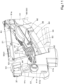
- the duct structure 50 extends from a position rearward of the operator's seat 6, via a space at one side (right side) of the operator's seat 6, to a position forward of the operator's seat 6. As shown in FIGS. 4 and 11 etc., the duct structure 50 extends in the front-rear direction through a space below (substantially below) the right manipulator 21.
- the right manipulator 21 includes manual operators such as the right operating lever 26 and the dozer operating lever 27, detector(s) (such as the first detector 32, the second detector) to detect operation of the manual operators and to output electric signals, and a mounting plate 36 to attach thereto manual operator(s) and/or detector(s).
- the duct structure 50 extends in the front-rear direction through a space below the manual operator(s), detector(s), mounting plate 36 and/or the like of the right manipulator 21.
- the right manipulator 21 is an electric controller to output electric signals in response to the operation of the right operating lever 26 or the dozer operating lever 27.
- the right manipulator 21 does not have connected thereto hoses (pilot hoses) to allow hydraulic fluid for use in the control by the operation of the right operating lever 26 to flow therethrough. Therefore, no pilot hoses are provided below the right manipulator 21.
- hoses pilot hoses
- the duct structure 50 includes a relay duct 51, a switching box 52, a first duct 53, a second duct 54, a third duct 55, and a fourth duct 56.
- the relay duct 51 connects the air conditioner body 29 and the switching box 52. As shown in FIG. 8 , a first end portion 51d of the relay duct 51 is connected to the air outlet 29A2 of the air conditioner body 29. A second end portion 51e of the relay duct 51 is connected to the switching box 52.
- the relay duct 51 is located rearward of the seat 6A of the operator's seat 6.
- the position of the first end portion of the relay duct 51 in the front-rear direction is located rearward of the operator's seat 6.
- the position of the second end portion of the relay duct 51 in the front-rear direction overlaps that of the operator's seat 6.
- the position of the second end portion of the relay duct 51 in the front-rear direction overlaps that of the backrest 6B of the operator's seat 6.
- the relay duct 51 allows the cool air and the warm air ejected from the air outlet 29A2 of the air conditioner body 29 to mix together, and guides the mixed air to the switching box 52.
- the relay duct 51 is long enough to allow the cool air and the warm air ejected from the air outlet 29A2 of the air conditioner body 29 to mix together (has a length that allows the cool air and the warm air to mix together).
- the cool air flow F1 and the warm air flow F2 are thoroughly mixed into a flow F3 while flowing through the relay duct 51.
- the air having passed through the relay duct 51 and introduced into the switching box 52 is conditioned air which is a thoroughly mixed mixture of cool air and warm air. That is, the internal space of the relay duct 51 functions as an preparation to the switching box 52 that allows cool air and warm air from the air conditioner body 29 to be thoroughly mixed.
- the relay duct 51 bends from the portion thereof that is connected to the air outlet 29A2 of the air conditioner body 29 and extends forward. As shown in FIGS. 4 and 12 , the relay duct 51 inclines such that the relay duct 51 extends diagonally forward and downward. Thus, since the relay duct 51 bends and inclines, cool air and warm air are easily mixed together.
- the relay duct 51 includes a passage enlarged portion 51f in which a cross-sectional area of a passage thereof increases in the direction from the air conditioner body 29 toward the switching box 52. That is, the cross-sectional area of the passage at the second end portion of the relay duct 51 is larger than that at the air outlet 29A2 of the air conditioner body 29. With this, the velocity of the air flowing through the relay duct 51 decreases as the air flows toward the switching box 52. Thus, it is possible to more reliably mix the cool air and the warm air.
- the relay duct 51 includes an extending portion 51a which extends upward.
- the extending portion 51a is provided at a rear portion (in the vicinity of the air outlet 29A2) of the relay duct 51.
- the upper end portion of the extending portion 51a is provided with a lid 51b.
- the lid 51b includes a first through-hole 51c.
- a cup holder 57 to hold a beverage container or the like is provided above the lid 51b of the extending portion 51a.
- the bottom of the cup holder 57 is located above the lid 51b.
- the bottom of the cup holder 57 includes a second through-hole 57a.
- a portion of the conditioned air ejected from the air outlet 29A2 of the air conditioner body 29 is guided to the extending portion 51a and released into the cup holder 57 through the first through-hole 51c and the second through-hole 57a. With this, it is possible to cool or warm the beverage container held by the cup holder 57.
- the switching box 52 is connected to the relay duct 51, the first duct 53, and the second duct 54.
- the switching box 52 includes a rear connection port 52a, a front connection port 52b, and a side connection port 52c.
- the rear connection port 52a has an opening facing rearward.
- the front connection port 52b has an opening facing forward.
- the side connection port 52c has an opening facing diagonally leftward and forward.
- the rear connection port 52a is connected to the relay duct 51.
- the front connection port 52b is connected to the first duct 53.
- the side connection port 52c is connected to the second duct 54.
- the switching box 52 is provided at one side (right) of the operator's seat 6. As shown in FIG. 4 , in side view, a portion or the entirety of the switching box 52 overlaps the operator's seat 6. The switching box 52 is provided below the right manipulator 21.
- the switching box 52 includes a switch portion 52d to switch between a first state in which the switching box 52 communicates with the first duct 53, and a second state in which the switching box 52 communicates with the second duct 54.
- the first state in which the switching box 52 communicates with the first duct 53 is a state in which the conditioned air supplied from the air conditioner body 29 is allowed to flow through the first duct 53.
- the second state in which the switching box 52 communicates with the second duct 54 is a state in which the conditioned air supplied from the air conditioner body 29 is allowed to flow through the second duct 54.
- the switch portion 52d includes a swing plate 52f swingable about a support shaft 52e.
- the swing plate 52f is swingable between (i) a first position (position indicated by a solid line) to close the side connection port 52c and open the front connection port 52b and (ii) a second position (indicated by a dot-dot-dash line) to close the front connection port 52b and open the side connection port 52c.
- the switching box 52 When the swing plate 52f is in the first position, the switching box 52 is in the first state to communicate with the first duct 53. When the swing plate 52f is in the second position, the switching box 52 is in the second state to communicate with the second duct 54.
- cool conditioned air flows in the relay duct 51
- the switching box 52 is in the first state, and cool conditioned air flows through the front connection port 52b into the first duct 53.
- warm conditioned air flows in the relay duct 51
- the switching box 52 When warm conditioned air flows in the relay duct 51, the switching box 52 is in the second state, and warm conditioned air flows through the side connection port 52c into the second duct 54.
- the swing plate 52f is swung by an electric drive mechanism such as an electric motor.
- the drive mechanism is driven by the operator operating an operating switch (not illustrated) provided in the vicinity of the operator's seat 6.
- the operating switch is, for example, a switch to switch between a cooling mode and a heating mode.
- the swing plate 52f When the operator switches the operating switch to the cooling mode, the swing plate 52f is brought into the first position, and cool air for cooling flows from the switching box 52 to the first duct 53. In so doing, cool conditioned air is generated in the air conditioner body 29, and that cool conditioned air is supplied to the switching box 52 via the relay duct 51.
- the swing plate 52f When the operator switches the operating switch to the heating mode, the swing plate 52f is brought into the second position, and warm air for heating flows from the switching box 52 to the second duct 54. In so doing, warm conditioned air is generated in the air conditioner body 29, and that warm conditioned air is supplied to the switching box 52 via the relay duct 51.
- the first duct 53 allows the cool conditioned air ejected from the switching box 52 to flow therethrough.
- the first duct 53 connects the switching box 52 and the third duct 55.
- (i) the first duct 53 and (ii) the combination of the relay duct 51, the switching box 52 and the second duct 54, are arranged in the machine body width direction.
- the first duct 53 includes a first portion 53a, a second portion 53b, and a third portion 53c.
- the first portion 53a, the second portion 53b, and the third portion 53c are integral with each other, and their internal spaces communicate with each other.
- the first portion 53a is a rectangular tube, and extends in the front-rear direction.
- the rear end portion of the first portion 53a is connected to the switching box 52, and the front end portion of the first portion 53a is connected to the third duct 55.
- the first portion 53a is a connector portion to connect the switching box 52 to the third duct 55 provided forward of the first duct 53.
- the first portion 53a inclines such that the first portion 53a extends diagonally forward and downward.
- the second portion 53b is a portion to connect the first portion 53a and the third portion 53c.
- the second portion 53b extends in a lateral direction (rightward) from a side surface (right side surface) of a rear portion of the first portion 53a and then bends to extend upward.
- the third portion 53c extends upward from the upper end of the second portion 53b.
- the third portion 53c is a flat portion shorter in the machine body width direction than in the front-rear direction.
- the third portion 53c is provided between the right manipulator 21 and an inner wall surface 5a of the cabin 5.
- the third portion 53c extends in the up-and-down direction through a space between the right manipulator 21 and the inner wall surface (right wall surface) 5a of the cabin 5 that faces the right manipulator 21. That is, the third portion (flat portion) 53c extends upward from the first portion (main portion) 53a along the inner wall surface 5a of the cabin 4.
- the third portion (flat portion) 53c is shorter than the first portion (main portion) 53a in the machine body width direction.
- the mounting plate 36 of the right manipulator 21A includes, at a right portion (one of opposite portions that is closer to the inner wall surface 5a) thereof, a cutout 36a which is recessed leftward (toward the operator's seat 6).
- the third portion 53c is fitted in the cutout 36a. As shown in FIGS. 12 and 13 , the third portion 53c extends rearward to a greater extent than the first portion 53a. As shown in FIG.10 , the third portion 53c extends rearward to a greater extent than the operator's seat 6.
- the first duct 53 includes first air outlet(s) 53d.
- the first air outlet 53d is an air outlet through which cool conditioned air is ejected.
- the first air outlets 53d include a front air outlet 53d1 and a rear air outlet 53d2.
- the front air outlet 53d1 is provided at an upper front portion of the third portion 53c.
- the rear air outlet 53d2 is provided at an upper rear portion of the third portion 53c.
- the front air outlet 53d1 is provided at one side (right side) of the operator's seat 6. As shown in FIG. 4 , the front air outlet 53d1 is positioned higher than the right manipulator 21. The position of the front air outlet 53d1 in the front-rear direction overlaps that of the seat 6A of the operator's seat 6. Specifically, the front end of the front air outlet 53d1 is located rearward of the front end of the seat 6A, and the rear end of the front air outlet 53d1 is located forward of the rear end of the seat 6A. The position (height) of the front air outlet 53d1 in the up-and-down direction overlaps that of the backrest 6B of the operator's seat 6. As shown in FIG. 12 , the front air outlet 53d1 has an opening facing diagonally leftward and upward.
- Cool conditioned air is blown diagonally leftward and upward (toward the space above the operator's seat 6) from the front air outlet 53d1 provided rightward of the seat 5A of the operator's seat 6 (see arrow Y1 in FIGS. 3 , 4 and 10 ). With this, cool conditioned air is blown toward the vicinity of the face (front of the face) of the operator OP seated on the operator's seat 6. Thus, cool conditioned air is blown to the vicinity of the face of the operator OP, giving a strong cool feeling to the operator OP.
- the rear air outlet 53d2 is located rearward of the operator's seat 6. As shown in FIG. 3 , the rear air outlet 53d2 is located rightward of the operator's seat 6. That is, the rear air outlet 53d2 is located diagonally rightward and rearward of the operator's seat 6. As shown in FIG. 4 , the rear air outlet 53d2 is located higher than the right manipulator 21. The position (height) of the rear air outlet 53d2 in the up-and-down direction overlaps that of the backrest 6B of the operator's seat 6. The rear air outlet 53d2 has an opening facing upward. A blowing pipe 58 is attached to the rear air outlet 53d2. The blowing pipe 58 has an opening facing diagonally forward and upward.
- Cool conditioned air is blown diagonally forward and upward from the rear air outlet 53d2 located diagonally rightward and rearward of the seat 5A of the operator's seat 6 via the blowing pipe 58 (see arrow Y2 in FIGS. 3 , 4 and 10 ). With this, cool conditioned air is blown toward the vicinity of the back of the head of the operator OP seated on the operator's seat 6.
- the second duct 54 is a duct to allow warm conditioned air from the switching box 52 to flow therethrough.
- the rear end portion of the second duct 54 is connected to the side connection port 52c of the switching box 52.
- the front-end portion of the second duct 54 is connected to the fourth duct 56.
- the second duct 54 inclines such that the second duct 54 extends diagonally forward and downward.
- the second duct 54 is provided below the right manipulator 21.
- the second duct 54 and the first portion 53a of the first duct 53 are arranged in the machine body width direction.
- the third duct 55 is a duct to guide forward the cool conditioned air having flowed through the first duct 53. As shown in FIGS. 3 , 4 , 10 and 12 , the third duct 55 extends forward from the front end of the first duct 53 and then bends to extend upward (diagonally forward and upward).
- the third duct 55 includes a second air outlet 55a.
- the second air outlet 55a is an air outlet through which cool conditioned air is blown out.
- the second air outlet 55a is located forward of the operator's seat 6. As shown in FIG.
- the position (height) of the second air outlet 55a in the up-and-down direction overlaps that of the seat 6A of the operator's seat 6, and is located at or substantially at the height of the seating surface of the seat 6A.
- the second air outlet 55a has, at a position diagonally rightward and forward of the operator's seat 6, an opening facing leftward (or diagonally leftward and rearward). Cool conditioned air is blown toward a space forward of the legs (the vicinity of the knees) of the operator OP seated on the operator's seat 6 from the second air outlet 55a (see arrow Y12 in FIGS. 3 , 4 and 10 ).
- the fourth duct 56 is a duct to guide forward warm conditioned air having passed through the second duct 54. As shown in FIGS. 3 , 4 , 10 and 12 , the fourth duct 56 extends forward from the front end of the second duct 54 and then bends to extend upward.
- the fourth duct 56 includes third air outlet(s) 56a.
- the third air outlet 56a is an air outlet through which warm conditioned air is blown out.
- the third air outlet 56a is provided in front of the operator's seat 6.
- the third air outlets 56a include a bottom air outlet 56a1, a side air outlet 56a2, and a top air outlet 56a3.
- the position of the bottom air outlet 56a1 in the up-and-down direction is lower than the seat 6A of the operator's seat 6.
- the bottom air outlet 56a1 has an opening facing downward (diagonally leftward and downward). The warm conditioned air blown from the bottom air outlet 56a1 flows toward the feet of the operator seated on the operator's seat 6 (see arrow Y13 in FIG. 4 ).
- the side air outlet 56a2 is located forward of the second air outlet 55a and the bottom air outlet 56a1.
- the position of the side air outlet 56a2 in the up-and-down direction is lower than the seating surface of the seat 6A of the operator's seat 6.
- the side air outlet 56a2 has an opening facing diagonally leftward and forward.
- the side air outlet 56a2 is an air outlet for defrosting. Warm conditioned air is blown from the side air outlet 56a2 diagonally leftward and forward (see arrow Y14 in FIG. 4 ). With this, it is possible to defog the front window of the cabin 5.
- the top air outlet 56a3 is located forward of the second air outlet 55a and the bottom air outlet 56a1.
- the position of the top air outlet 56a3 in the up-and-down direction is higher than the second air outlet 55a.
- the top air outlet 56a3 has an opening facing diagonally leftward and forward.
- the top air outlet 56a3 is an air outlet for defrosting. Warm conditioned air is blown from the top air outlet 56a3 diagonally leftward and forward (see arrow Y15 in FIGS. 3 , 4 and 10 ). With this, it is possible to defog the front window of the cabin 5.
- the working machine 1 includes cover member(s) 60 to cover the duct structure 50.
- the cover members 60 include a first cover member 61, a second cover member 62, a third cover member 63, and a fourth cover member 64. Note that, only the third cover member 63 is illustrated in FIG. 4 , and only the second cover member 62 is illustrated in FIG. 15 .
- the first cover member 61 covers a front portion of the duct structure 50.
- the first cover member 61 covers and surrounds the third duct 55 and the fourth duct 56.
- the first cover member 61 includes a first vent 61a, a second vent 61b, a third vent 61c, and a fourth vent 61d.
- the first vent 61a is provided at a position corresponding to the bottom air outlet 56a1.
- the second vent 61b is provided at the side air outlet 56a2.
- the third vent 61c is provided at a position corresponding to the top air outlet 56a3.
- the fourth vent 61d is provided at a position corresponding to the second air outlet 55a.
- the display 33 is attached to the top end of the first cover member 61 via a bracket 37 (see FIG. 11 and the like).
- the second cover member 62 covers the left side of the first portion 53a of the first duct 53, the left side of the second duct 54, the left side of the switching box 52, and the left side of a front portion of the relay duct 51.
- the second cover member 62 covers the left side of the portion of the duct structure 50 that is provided below the right manipulator 21.
- the third cover member 63 covers the left and upper sides of the second portion 53b of the first duct 53.
- the third cover member 63 covers the portion of the second portion 53b that projects upward from the right manipulator 21.
- the third cover member 63 includes a fourth vent 63a at a position corresponding to the front air outlet 53d1.
- the fourth cover member 64 covers the left and upper sides of a rear portion of the relay duct 51, and the upper side of a rear portion of the first duct 53.
- the fourth cover member 64 is provided rearward of the right manipulator 21.
- the fourth cover member 64 includes a first hole 64a at a position corresponding to the blowing pipe 58, and a second hole 64b at a position corresponding to the cup holder 57.
- the cover members 60 With the duct structure 50 covered by the cover members 60, it is possible to prevent or reduce the breakage or deformation of the duct structure 50. It is possible to prevent or reduce changes in temperature of the conditioned air flowing inside the duct structure 50.
- the air conditioner body 29 is connected to an inside/outside-air switching device 65.
- the inside/outside-air switching device 65 is connected to the air inlet 29A1 of the housing 29A of the air conditioner body 29.
- the inside/outside-air switching device 65 is provided above the blower fan 29D of the air conditioner body 29.
- the inside/outside-air switching device 65 is provided rearward of the operator's seat 6. The inside/outside-air switching device 65 switches between a state in which outside air is allowed to enter the air conditioner body 29, and a state in which inside air is allowed to enter the air conditioner body 29.
- the inside/outside-air switching device 65 includes a housing 65a, and a switch damper 65b provided inside the housing 65a.
- the housing 65a includes an inside air intake 65c and an outside air intake 65d.
- the inside air intake 65c has an opening facing upward.
- the outside air intake 65d has an opening facing rearward.
- the switch damper 65b is swingable about a support shaft 52e.
- the switch damper 65b is swingable between a first position (position indicated by solid lines) to open the inside air intake 65c and close the outside air intake 65d, and a second position (position indicated by dot-dot-sash lines) to open the outside air intake 65d and close the inside air intake 65c. It is possible to perform the switching (swinging) of the switch damper 65b between the first position and the second position using a selection switch (not illustrated) provided in the vicinity of the operator's seat 6.
- an outside air duct 66 is connected to the outside air intake 65d of the inside/outside-air switching device 65.
- the outside air duct 66 is a duct to guide outside air to the outside air intake 65d.
- the outside air duct 66 extends in the front-rear direction, and its front portion is connected to the outside air intake 65d.
- the outside air duct 66 extends rearward from the outside air intake 65d, and increases in width (dimension in the machine body width direction) in the rearward direction.
- the outside air duct 66 is attached to an opening 5c provided at a back surface 5b of the cabin 5.
- a bulging portion 5d bulging rearward such that the inner space at the rear portion of the cabin 5 expands is provided at the back surface 5b of the cabin 5.
- the bulging portion 5d includes the opening 5c.
- the opening 5c communicates with the inner space of the cabin 5.
- the outside air duct 66 includes a flange 66a. By fixing the bulging portion 5d and the flange 66a with fastener(s) such as bolt(s), the outside air duct 66 is fixed to the bulging portion 5d (see FIG. 18 ). In the state where the outside air duct 66 is fixed to the bulging portion 5d, the front portion of the outside air duct 66 is inserted through the opening 5c in the cabin 5 (see FIG. 9 ).
- a first filter 71 and a second filter 72 are attached to the outside air duct 66.
- the first filter 71 and the second filter 72 are attached to a rear portion of the outside air duct 66.
- the first filter 71 includes a filter body 71A and a holding portion 71B to hold the filter body 71A.
- the filter body 71A is positioned such that the filter body 71A overlaps the second filter 72 in rear view.
- the holding portion 71B includes an outer periphery portion 71B 1 provided around the filter body 71A and an extension portion 71B2 extending rearward from the outer periphery portion 71B1.
- the extension portion 71B2 is a rectangular tube, and is fitted in an opening 66b at a rear portion of the outside air duct 66.
- the first filter 71 and the second filter 72 are fixed to a rear portion of the outside air duct 66 by a frame 73.
- the frame 73 fixes the second filter 72 and the first filter 71 to the outside air duct 66.
- the frame 73 fixes the second filter 72 and the first filter 71, which are stacked on top of each other, to the outside air duct 66.
- the second filter 72 is exposed through the opening of the frame 73.
- the frame 73 includes an engaged portion 73a and a fixed portion 73b.
- the engaged portion 73a is provided at a right portion of the frame 73.
- the engaged portion 73a is a portion to be engaged with the outside air duct 66.
- the outside air duct 66 includes an engagement hole 66c at a rear right portion thereof.
- the fixed portion 73b is provided at a left portion of the frame 73.
- the fixed portion 73b is a portion to be fixed to the outside air duct 66.
- the fixed portion 73b includes a through-hole 73c.
- the outside air duct 66 includes, at a rear left portion thereof, a receiving portion 66d.
- the receiving portion 66d A includes a threaded hole 66e.
- the first filter 71 and the second filter 72 are arranged in the front-rear direction.
- the first filter 71 and the second filter 72 are arranged such that they overlap the outside air inlets 34 (see FIG. 7 and the like) in rear view.
- the first filter 71 is attached to the rear portion of the outside air duct 66.
- the second filter 72 is provided between the outside air inlets 34 and the first filter 71 in the front-rear direction. That is, the second filter 72 is located closer to the outside air inlets 34 than the first filter 71 is.
- the first filter 71 and the second filter 72 remove foreign matter from the outside air taken in through the outside air inlets 34. Specifically, first, the second filter 72 removes foreign matter from the outside air taken in through the outside air inlets 34, and then the first filter 71 removes foreign matter from the outside air which passed through the second filter 72.
- the second filter 72 is coarser than the first filter 71.
- the first filter 71 is finer than the second filter 72. That is, the first filter 71 is a fine filter that can remove finer foreign matter than the second filter 72. Since the second filter 72 is located closer to the outside air inlets 34 than the first filter 71 is, clogging of the fine mesh first filter 71 is less likely to occur, and it is possible to increase the lifetime of the first filter 71.
- the outside air taken in through the outside air inlets 34 and passed through the first filter 71 and the second filter 72 is guided by the outside air duct 66 to the outside air intake 65d of the inside/outside-air switching device 65, and is guided to the air conditioner body 29.
- the back surface 5b of the cabin 5 has attached thereto a rear cover 77 projecting rearward from the back surface 5b.
- the outside air inlets 34 are provided in the rear cover 77.
- the rear cover 77 is provided at a lower portion (below the rear window 5e) of the back surface 5b of the cabin 5.
- the rear cover 77 is detachably attached to the back surface 5b of the cabin 5.
- the rear cover 77 includes a first attachment portion 77a, a second attachment portion 77b, and a third attachment portion 77c.
- the first attachment portion 77a includes first attachment hole(s) 77d.
- the second attachment portion 77b includes second attachment hole(s) 77e.
- the third attachment portion 77c includes third attachment hole(s) 77f.
- a first bracket 78, a second bracket 79, and a third bracket 80 are attached to a lower portion of the back surface 5b of the cabin 5.
- the first bracket 78 includes first receiving hole(s) 78a.
- the second bracket 79 includes second receiving hole(s) 79a.
- the third bracket 80 includes third receiving hole(s) 80a.
- the rear cover 77 is attached to the back surface 5b of the cabin 5 by, using bolts and nuts, fastening the first attachment hole(s) 77d and the first receiving hole(s) which are stacked together, the second attachment hole(s) 77e and the second receiving hole(s) 79a which are stacked together, and the third attachment hole(s) 77f and the third receiving hole(s) 80a which are stacked together.
- the rear cover 77 is provided above the sixth cover 43F.
- the position of the rear cover 77 in the up-and-down direction overlaps that of the operator's seat 6.
- the upper end of the rear cover 77 is located lower than the upper end of the operator's seat 6.
- the lower end of the rear cover 77 is located higher than the lower end of the operator's seat 6.
- the position of the rear cover 77 in the machine body width direction overlaps that of the operator's seat 6.
- the right end of the rear cover 77 is located leftward of the right end of the operator's seat 6.
- the left end of the rear cover 77 is located leftward of the left end of the operator's seat 6 or at the same position or substantially at the same position as the left end of the operator's seat 6.
- the width of the rear cover 77 (dimension in the machine body width direction) is longer than the width of the operator's seat 6 (dimension in the machine body width direction).
- the rear cover 77 covers the rear side of the air conditioner body 29 provided inside the cabin 5.
- the front portion of the air conditioner body 29 is provided inside of the cabin 5.
- the rear portion of the air conditioner body 29 projects rearward from the cabin 5.
- the rear cover 77 covers the rear portion of the air conditioner body 29 that projects rearward from the cabin 5.
- the rear portion of the air conditioner body 29 does not need to project rearward from the cabin 5. That is, the entirety of the air conditioner body 29 may be provided inside the cabin 5 (in front of the rear cover 77).
- At least the first filter 71, the second filter 72, and the outside air duct 66 are provided inside the rear cover 77 (see FIG. 10 ).
- the rear cover 77 includes a lid 81.
- the lid 81 is a rectangle longer in the machine body direction than in the up-and-down direction in rear view.
- the rear cover 77 includes a rear portion opening 77g, and the lid 81 is attached to cover the rear portion opening 77g.
- the lid 81 is openable and closeable relative to the rear cover 77 (see arrow Y5 of FIG. 2 ).
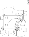
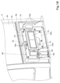
- the lid 81 is open, the second filter 72 and the frame 73 are exposed through the rear portion opening 77g (see FIG. 21 ). With this, it is possible to remove the frame 73 from the outside air duct 66 to perform replacement or the like of the first filter 71 and the second filter 72.
- hinge(s) 82 is/are attached to a right edge portion of the lid 81.
- the hinge 82 is attached to the right edge of the rear portion opening 77g of the rear cover 77 (see FIGS. 20 and 21 ).
- the lid 81 is openable about the hinge 82 in a direction diagonally rightward and rearward (see arrow Y5 in FIG. 2 ).
- the lid 81 includes a keyhole 81b in a left portion thereof.
- cushioning 83 is provided in the vicinity of the left edge of the rear portion opening 77g in the rear cover 77.
- the cushioning 83 includes an elastic body such as a rubber.
- the cushioning 83 is positioned such that the cushioning 83 faces the rear portion opening 77g.
- the cushioning 83 abuts the front surface of the lid 81 to elastically deform. With this, it is possible to eliminate or reduce the likelihood that the lid 81 will rattle when the lid 81 is closed.
- the outside air inlets 34 are provided in the lid 81.
- the outside air inlets 34 are openings to allow air outside the cabin 5 (outside air) to be introduced therethrough into the cabin 5. Outside air is introduced through the outside air inlets 34 by driving the blower fan 29D of the air conditioner body 29.
- the outside air inlets 34 are provided.
- the outside air inlets 34 are elongated holes longer in the machine body width direction than in the up-and-down direction.
- the lid 81 includes, at an upper portion thereof, an area 81R where no outside air inlets 34 are provided. In other words, the outside air inlets 34 are not provided in the area 81R at the upper portion of the lid 81.
- a first rib 84A and a second rib 84B are provided on the front surface of the lid 81.
- the first rib 84A is provided at a right portion of the front surface of the lid 81.
- the second rib 84B is provided at a left portion of the front surface of the lid 81.
- the first rib 84A and the second rib 84B extend parallel to each other and each extend in the up-and-down direction.
- a case 85 is attached to a front portion (front surface) of the lid 81.
- a net 86 is housed in the case 85.
- the net 86 is an insect catching net to catch insects and/or the like entering through the outside air inlets 34.
- the net 86 is coarser than the second filter 72.
- the case 85 includes a front panel 85a and a peripheral wall 85b.
- the front panel 85a is a rectangle longer in the machine body direction than in the up-and-down direction length.
- the front panel 85a includes opening(s) 85c.
- a plurality of (sixteen in the illustrated example) the openings 85c are provided.
- the openings 85c are elongated holes longer in the up-and-down direction than in the machine body width direction.
- the openings 85c allow passage of outside air taken in through the outside air inlets 34.
- the front panel 85a includes, at a lower portion thereof, an area 85R where no openings 85c are provided. In other words, the openings 85c are not provided in the area 85R at the lower portion of the front panel 85a.
- the front panel 85a is positioned such that the front panel 85a faces the outside air inlets 34.
- the net 86 is provided rearward of the front panel 85a.
- the peripheral wall 85b extends rearward from the outer edge of the front panel 85a. Attachment portion(s) 85d is/are provided on the peripheral wall 85b.
- a space SP1 is defined between the front panel 85a and the lid 81.
- the net 86 can be provided in the space SP1.
- the net 86 is provided between the first rib 84A and the second rib 84B (see FIG. 23 ).
- the net 86 is positioned in the vicinity of the lid 81 such that the net 86 faces the outside air inlets 34 of the lid 81.
- the net 86 is located closer to the outside air inlets 34 than the second filter 72 (see FIG. 10 ) provided at a position away from the lid 81. That is, when the net 86 is provided in the space SP1, the net 86 is provided between the outside air inlets 34 and the second filter 72. With this, it is possible to catch insects and/or the like entered through the outside air inlets 34 using the net 86 before the insects reach the second filter 72.
- the openings 85c are located higher than the outside air inlets 34. That is, the height H1 of the lower edge of the openings 85c is higher than the height H2 of the upper edge of the outside air inlets 34.
- the outside air inlets 34 are provided such that the outside air inlets 34 face the area 85R with no openings 85c.
- the openings 85c are provided such that the openings 85c face the area 81R with no outside air inlets 34.
- the washing water entered through the outside air inlets 34 hits the area 85R and flows down, it is possible to eliminate or reduce the likelihood that the washing water will enter the openings 85c (see arrow Y6 in FIG. 26 ).
- the washing water that hit the area 85R and flowed down passes through a gap GP2 between the front panel 85a and the net 86 and a gap GP3 between the lid 81 and the rear cover 77, and goes out of the machine body 2.
- the outside air taken in through the outside air inlets 34 can move upward and enter the openings 85c (see arrow Y7 in FIG. 26 ).
- the peripheral wall 85b of the case 85 extends rearward from a lower portion, a left portion, and a right portion of the outer edge of the front panel 85a. That is, the peripheral wall 85b is not provided at an upper edge of the front panel 85a.
- a large gap GP1 is defined between the case 85 and the lid 81 at an upper portion of the case 85 (see FIGS. 24 and 26 ).
- the first rib 84A and the second rib 84B function as guides to guide the movements of the net 86.
- a holding frame 87 to hold the net 86 is provided around the net 86.
- the holding frame 87 has a rectangular annular shape.
- the holding frame 87 is provided, at an upper portion thereof, with a fixing portion 87a to be used to fix the holding frame 87 and the net 86 to the case 85.
- the fixing portion 87a extends forward from an upper portion of the holding frame 87 and then bends to extend downward.
- the fixing portion 87a includes a through-hole 87b.
- a receiving portion 85e is provided on the front surface of the front panel 85a of the case 85.
- the receiving portion 85e is a portion to have the fixing portion 87a fixed thereto.
- the receiving portion 85e projects forward from an upper portion of the front panel 85a.
- the receiving portion 85e includes a threaded hole 85f.
- the case 85 includes projecting portion(s) 85g projecting rearward (toward the outside air inlets 34) from the front panel 85a.
- the projecting portions 85g include a first projecting portion 85g1 provided at a left portion of the front panel 85a, and a second projecting portion 85g2 provided at a right portion of the front panel 85a.
- the first projecting portion 85g1 and the second projecting portion 85g2 each extend in the up-and-down direction and extend parallel to each other. The extent to which the projecting portion 85g projects increases in the top-to-bottom direction.
- the projecting portions 85g abut the front surface of the net 86.
- the net 86 is pressed toward the lid 81 by the projecting portions 85g, and abuts or is present near the outside air inlets 34. Since the extent to which the projecting portions 85g project increases in the top-to-bottom direction, it is possible to reliably cause the projecting portions 85g to abut the front surface of the net 86. Since the extent to which the projecting portions 85g project is small at an upper portion, it is possible to easily perform work to place the net 86 into the case 85 from above.
- the working machine 1 includes a holding portion 90 to hold the lid 81 in the open state.
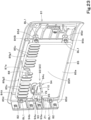
- the holding portion 90 includes a holding member 91 provided at the rear cover 77 (see FIGS. 20 , 21 and 26 ), and a holding mechanism 92 provided at the case 85 (see FIGS. 22 , 23 and 26 ).
- the holding member 91 is provided at the outer edge of the rear portion opening 77g of the rear cover 77. Specifically, the holding member 91 projects from a right portion of the outer edge of the rear portion opening 77g of the rear cover 77 leftward (toward the center of the rear portion opening 77g).
- the holding member 91 is provided between the two hinges 82 arranged in the up-and-down direction.
- the holding member 91 is a flat plate including opposite surfaces one of which faces upward and the other of which faces downward.
- the holding member 91 includes a through-hole 91a extending in the up-and-down direction.
- the holding mechanism 92 is provided at the front surface of the front panel 85a of the case 85.
- the holding mechanism 92 includes a support portion 93, a stay 94, and an engagement portion 95.
- the support portion 93 projects forward from the front surface of the front panel 85a.
- the support portion 93 includes a through-hole 93a extending in the up-and-down direction.
- the support portion 93 supports the stay 94 rotatably about an axis Z1 in the up-and-down direction.
- the stay 94 includes a first portion 94a, a second portion 94b, and a third portion 94c.
- the first portion 94a extends in the up-and-down direction, and is inserted from above into the through-hole 93a in the support portion 93.
- the second portion 94b bends from the upper end of the first portion 94a and extends in a horizontal direction.
- the third portion 94c bends from the second portion 94b and extends downward.
- the third portion 94c is spaced from the first portion 94a and is provided in parallel to the first portion 94a.
- the engagement portion 95 is provided at the front surface of the front panel 85a, and is configured to have the second portion 94b of the stay 94 engaged therewith.
- the engagement portion 95 is obtained by bending a metallic plate with spring properties.
- the engagement portion 95 can detachably hold the second portion 94b by the spring properties of the metallic plate.
- the second portion 94b is held by being pinched by the metallic plate from above and below.
- the second portion 94b of the stay 94 is engaged with the engagement portion 95 (see FIGS. 23 and 27 ).
- the stay 94 is caused to rotate in the second direction about the axis Z1 (direction of arrow Y10 in FIG. 23 , direction of arrow Y11 in FIG. 28 ) to disengage the second portion 94b from the engagement portion 95, and the third portion 94c is inserted from above into the through-hole 91a in the holding member 91 (see FIG. 28 ).
- the working machine 1 includes a filter structure including a net 86, a first filter 71 and a second filter 72 to remove foreign matter from outside air introduced through the outside air inlets 34.
- the outside air introduced through the outside air inlets 34 into the rear cover 77 passes through the net 86, the second filter 72, and then the first filter 71 (in this order). With this, the foreign matter contained in the outside air is removed.
- the outside air from which foreign matter has been removed is supplied from the inside/outside-air switching device 65 to the air conditioner body 29.
- the air conditioner body 29 generates conditioned air, and the generated conditioned air is blown into the foregoing duct structure 50.
- connection structure of the duct structure 50 will now be described.
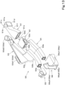
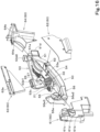
- the duct structure 50 includes a relay duct 51, a switching box 52, a first duct 53, a second duct 54, a third duct 55, and a fourth duct 56 (see FIGS. 12 and 13 ).
- the duct structure 50 includes a plurality of ducts (including the switching box 52) connected together.
- the duct structure 50 includes one duct and another duct connected together.
- the duct structure 50 includes the relay duct (one duct) 51 and the switching box (another duct) 52 connected together.
- the duct structure 50 includes the switching box (one duct) 52 and the first duct (another duct) 53 connected together.
- the duct structure 50 includes the switching box (one duct) 52 and the second duct (another duct) 54 connected together.
- the duct structure 50 includes the first duct (one duct) 53 and the third duct (another duct) 55 connected together.
- the duct structure 50 includes the second duct (one duct) 54 and the fourth duct (another duct) 56 connected together.
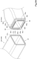
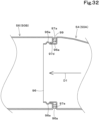
- FIGS. 29 and 30 each illustrate a case where one duct 50A is the first duct 53, and another duct 50B is the third duct 55.
- the one duct 50A (first duct 53) includes a first connector portion 96 inserted into and connected to the another duct 50B (third duct 55).
- the another duct 50B (third duct 55) includes a second connector portion 97 to receive and to be connected to the one duct 50A (first duct 53).
- the first connector portion 96 includes a first end surface 96a perpendicular to a direction D1 of insertion of the one duct 50A (first duct 53).
- the first connector portion 96 includes a tubular portion 96c extending from a radially innermost portion 96b of the first end surface 96a toward the another duct 50B (third duct 55).
- the first end surface 96a is a surface extending from an outer peripheral surface 96d of the one duct 50A (first duct 53) inward (in the direction approaching the central axis of the duct 50A).
- the first end surface 96a is an annular (rectangular annular) flat surface.
- the first end surface 96a is provided to surround the outer periphery of the tubular portion 96c.
- the tubular portion 96c is provided with projection(s) 96e on the outer surface thereof.
- the projection 96e projects from an outer surface 96f of the tubular portion 96c outward (in a direction away from the central axis of the duct 50A).
- the projection 96e is elongated in a direction perpendicular to the insertion direction D1.
- the projection 96e is a projecting ridge extending along a circumferential direction of the tubular portion 96c.
- the projection 96e may be provided on the entire perimeter of the tubular portion 96c, or may be provided only on a portion of the perimeter of the tubular portion 96c.
- the projection 96e is provided on each of the four outer surfaces 96f of the rectangular tubular portion 96c. Each projection 96e projects in the form of an arc from the corresponding outer surface 96f of the tubular portion 96c.
- An inner surface 96g of the tubular portion 96c includes, at a position corresponding to the projection 96e, a recess 96h recessed toward the outer surface.
- the second connector portion 97 includes a second end surface 97a which faces the first end surface 96a.
- the second end surface 97a is also a surface perpendicular to the insertion direction D1.
- the second end surface 97a is parallel to the first end surface 96a.
- the second end surface 97a is a surface extending inward (in a direction approaching the central axis of the duct) from an outside edge 97b of the another duct 50B (third duct 55).
- the second end surface 97a is an annular (rectangular annular) flat surface.
- the second connector portion 97 includes a folded portion 97d folded from a radially innermost portion 97c of the second end surface 97a in a direction away from the first end surface 96a (in a direction opposite to the insertion direction D1).
- the folded portion 97d may be provided at the entire perimeter of the radially innermost portion 97c of the second end surface 97a, or may be provided only at a portion of the perimeter of the radially innermost portion 97c of the second end surface 97a.
- the folded portion 97d is provided along the entire perimeter of the radially innermost portion 97c of the second end surface 97a.
- the folded portion 97d is engaged with the tubular portion 96c, and the another duct 50B (third duct 55) is less likely to fall off from the one duct 50A (first duct 53). That is, the one duct 50A and the another duct 50B are connected.
- the one duct 50A and the another duct 50B can be produced using a flexible synthetic resin. With this, when the one duct 50A and the another duct 50B are attached to or detached from each other, the folded portion 97d is pushed by the projections 96e and bends outward (undergoes elastic deformation). Thus, it is possible to easily attach and detach the first duct and the second duct.
- the folded portion 97d abuts or is located near the outer surface 96f of the tubular portion 96c (specifically, the portion of the outer surface 96f that is located rearward of the projections 96e in the insertion direction D1) (see FIG. 30 ). With this, it is possible to eliminate o reduce the likelihood that the junction of the one duct 50A and the another duct 50B will rattle.
- the second connector portion 97 of the another duct 50B includes the folded portion 97d as described above, in the case where the another duct 50B is produced by blow molding, it is possible to produce the inner surface of the second connector portion 97 (inner surface 97e of the folded portion 97d) with high precision. This is described below with reference to FIG. 31 .
- the inner surface of the connector portion is a cut surface formed with a cutter (manually cut surface).
- a cutter manufactured with a cutter
- cushioning 99 is interposed between the first end surface 96a and the second end surface 97a.
- the cushioning 99 includes an elastic body such as a rubber.
- the base material for the cushioning 99 may be ethylene propylene diene monomer (EPDM) rubber, for example.
- the cushioning 99 is bonded to the first end surface 96a or the second end surface 97a. In the present embodiment, the cushioning 99 is bonded to the first end surface 96a. However, the cushioning 99 may be bonded to the second end surface 97a. As shown in FIG. 29 , the cushioning 99 is an annular (rectangular annular) member. The cushioning 99 is provided to surround the outer perimeter of the tubular portion 96c.
- the cushioning 99 is provided between the first end surface 96a and the second end surface 97a. In this state, the cushioning 99 abuts the first end surface 96a and the second end surface 97a. In this state, the cushioning 99 may abut the first end surface 96a, the second end surface 97a, and the outer surface of the tubular portion 96c.
- the cushioning 99 is interposed between the first end surface 96a perpendicular to the insertion direction D1 and the second end surface 97a facing the first end surface 96a, when the one duct 50A and the another duct 50B are attached to or detached from each other, the inner surfaces of the ducts are not rubbed against the outer surface of the cushioning 99. With this, when the one duct 50A and the another duct 50B are attached to or detached from each other, it is possible to eliminate or reduce the likelihood that the cushioning 99 will come off.
- the foregoing duct connection configuration (the connection configuration of the one duct 50A and the another duct 50B) is also applicable to the case where the one duct 50A is the relay duct 51 and the another duct 50B is the switching box 52. That is, as shown in FIG. 14 , the foregoing duct connection configuration is also applicable to the connection configuration of the relay duct 51 and the switching box 52.
- the foregoing duct connection configuration is also applicable to the case where the one duct 50A is the switching box 52 and the another duct 50B is the first duct 53. That is, as shown in FIG. 14 , the foregoing duct connection configuration is also applicable to the connection configuration of the switching box 52 and the first duct 53.
- the foregoing duct connection configuration is also applicable to the case where the one duct 50A is the switching box 52 and the another duct 50B is the second duct 54. That is, as shown in FIG. 14 , the foregoing duct connection configuration is also applicable to the connection configuration of the switching box 52 and the second duct 54.
- the foregoing duct connection configuration is also applicable to the case where the one duct 50A is the second duct 54 and the another duct 50B is the fourth duct 56. That is, as shown in FIG. 32 , the foregoing duct connection configuration is also applicable to the connection configuration of the second duct 54 and the fourth duct 56.
- a working machine 1 as has been described includes a machine body 2, a cabin 5 on the machine body, an operator's seat 6 provided inside the cabin 5, and an air conditioner body 29 to generate conditioned air to be supplied into the cabin 5, wherein the cabin 5 includes, at a back surface 5b thereof, an outside air inlet 34 to allow outside air to be introduced therethrough into the air conditioner body 29.
- the outside air inlet(s) 34 is/are provided at the back surface of the cabin 5 where a large space is available compared to a side surface of the cabin 5.
- a filter first filter 71
- high performance for example, Category2 of EN standards, MARV-16 of OSHA standards, or the like.
- a different filter such as the second filter 72 or the net body 86
- the air conditioner body 29 is located rearward of the operator's seat 6.
- the back surface 5b of the cabin 5 has attached thereto a rear cover 77 projecting rearward from the back surface 5b.
- the outside air inlet 34 is provided in the rear cover 77.
- the rear cover 77 makes it possible to keep a large space available for the air conditioner body 29 and/or the like behind the operator's seat 6.
- the air conditioner body 29 and/or the like behind the operator's seat 6 without increasing the size of the cabin 5.
- the rear cover 77 includes a lid 81 closeable and openable, and the outside air inlet 34 is provided in the lid 81.
- the working machine 1 further includes a first filter 71 to remove foreign matter contained in outside air introduced through the outside air inlet 34, and an outside air duct 66 to guide outside air that has passed through the first filter 71 toward the air conditioner body 29.
- the first filter 71 is attached to the outside air duct 66.
- the working machine 1 further includes a second filter 72 coarser than the first filter 71 and provided between the outside air inlet 34 and the first filter 71, and a frame 73 to fix the second filter 72 and the first filter 71 to the outside air duct 66.
- outside air taken in through the outside air inlets 34 can be passed through the second filter 72 and then supplied to the first filter 71, making the first filter 71 less likely to be clogged and making it possible to increase the lifetime of the first filter 71. Furthermore, since the first filter 71 and the second filter 72 are unfastened by detaching the frame 73, it is possible to easily perform work to replace the first filter 71 and the second filter 72.
- the working machine 1 further includes an insect catching net provided between the outside air inlet 34 and the second filter 72.
- the lid 81 has, attached to a front portion thereof, a case 85 to house a net 86 such that the net 86 is removable.
- the case 85 includes a front panel 85a provided forward of the net 86 such that the front panel 85a faces the outside air inlet 34.
- the front panel 85a includes an opening 85c to allow passage of outside air taken in through the outside air inlet 34.
- the opening 85c is located higher than the outside air inlet 34.
- the case 85 includes a projecting portion 85g projecting from the front panel 85a toward the outside air inlet 34 and configured to abut a front surface of the net 86.
- the extent to which the projecting portion 85g projects increases in a top-to-bottom direction.
- the projecting portion(s) 85g press the net 86 against the lid 81. With this, it is possible to place the net 86 such that the net 86 abuts or is present near the outside air inlets 34. Furthermore, since the extent to which the projecting portion(s) 85g project(s) increases in the top-to-bottom direction, it is possible to reliably cause at least the bottom portion of the projecting portion 85g to abut the net 86. Furthermore, since the extent to which the projecting portion(s) 85g project(s) is small at the upper portion, it is possible to easily perform work to place the net 86 into the case 85 from above.
- a working machine 1 includes a machine body 2, a cabin 5 on the machine body 2, an operator's seat 6 provided inside the cabin 5, an air conditioner body 29 to generate conditioned air to be supplied into the cabin 5, and a duct structure 50 to guide conditioned air supplied from the air conditioner body 29, wherein the air conditioner body 29 is operable to mix cool air and warm air to generate conditioned air for cooling or heating, the duct structure 50 includes a first duct 53 to allow conditioned air for cooling to flow therethrough, a second duct 54 to allow conditioned air for heating to flow therethrough, a switching box 52 connected to the first duct 53 and the second duct 54 and including a switch portion 52d to switch between a first state in which conditioned air supplied from the air conditioner body 29 is allowed to flow through the first duct 53, and a second state in which conditioned air supplied from the air conditioner body 29 is allowed to flow through the second duct 54, and a relay duct 51 to connect the air conditioner body 29 and the switching box 52 to guide conditioned air generated by the air conditioner body 29 to the switching box
- the air conditioner body 29 is located rearward of the operator's seat 6.
- the duct structure 50 extends from a position rearward of the operator's seat 6, via a space at one side of the operator's seat 6, to a position forward of the operator's seat 6.
- the air conditioner body 29 is located rearward of the operator's seat 6, the distance from the air conditioner body 29 to the switching box 52 is long. Thus, it is possible to thoroughly mix cool air and warm air in the relay duct 51 and then guide the air into the switching box 52. Furthermore, compared to when the air conditioner body 29 and the duct structure 50 are provided below the operator's seat 6, it is possible to increase a space in the vicinity of the feet of the operator seated on the operator's seat 6.
- the working machine 1 further includes a manipulator (right manipulator 21) provided at one side of the operator's seat 6.
- the first duct 53 extends between the manipulator (right manipulator 21) and an inner wall surface 5a of the cabin 5 that faces the manipulator (right manipulator 21).
- the first duct 53 it is possible to place the first duct 53 such that the first duct 53 extends in the front-rear direction through a space at one side of the operator seated on the operator's seat 6.
- the first duct 53 it is possible to eject conditioned air for cooling through the first duct 53 in the vicinity of the operator seated on the operator's seat 6 (for example, in the vicinity of the face of the operator).
- the first duct 53 includes a first air outlet 53d.
- the first air outlet 53d includes a front air outlet 53d1 which includes an opening located at the one side of the operator's seat 6 and higher than the manipulator (right manipulator 21).
- the first air outlet 53d of known techniques is provided in the vicinity of the display 33 located forward of the operator's seat 6, it is difficult to increase the size of the display 33. In this regard, since the first air outlet 53d is located at a distance from the display 33, it is possible to increase the size of the display 33.
- the first air outlet 53d includes a rear air outlet 53d2 which includes an opening located rearward of the operator's seat 6.
- the switching box 52 is provided at the one side of the operator's seat 6.
- the duct structure 50 extends through a space below the manipulator (right manipulator 21) in a front-rear direction.
- the first duct 53 includes a flat portion (third portion 53c) which is shorter in a machine body width direction than in a front-rear direction.
- the flat portion is provided between the manipulator (right manipulator 21) and the inner wall surface 5a of the cabin 5.
- the flat portion (third portion 53c) includes a front air outlet 53d1 at a front portion thereof, and includes a rear air outlet 53d2 at a rear portion thereof.
- the first duct 53 includes a main portion (first portion 53a) to connect the switching box 52 and a third duct 55 provided forward of the first duct 53, and the flat portion (third portion 53c) extending upward from the main portion along the inner wall surface 5a of the cabin 5.
- the flat portion is shorter than the main portion in the machine body width direction.
- the relay duct 51 includes a passage enlarged portion 51f in which a cross-sectional area of a passage thereof increases in a direction from the air conditioner body 29 toward the switching box 52.
- a working machine 1 includes a machine body 2, a cabin 5 on the machine body 2, an air conditioner body 29 to generate conditioned air to be supplied into the cabin 5, and a duct structure 50 to guide conditioned air supplied from the air conditioner body 29, wherein the duct structure 50 includes one duct 50A and another duct 50B connected together, the one duct 50A includes a first connector portion 96 to be inserted into and connected to the another duct 50B, the another duct 50B includes a second connector portion 97 to receive and to be connected to the one duct 50A, the first connector portion 96 includes a first end surface 96a perpendicular to a direction in which the first connector portion 96 is inserted, the second connector portion 97 includes a second end surface 97a to face the first end surface 96a, and cushioning 99 is interposed between the first end surface 96a and the second end surface 97a.
- the cushioning 99 is interposed between the first end surface 96a perpendicular to the insertion direction and the second end surface 97a facing the first end surface 96a, the cushioning 99 is not rubbed against the ducts when the one duct 50A and the another duct 50B are attached to or detached from each other.
- the cushioning 99 is not rubbed against the ducts when the one duct 50A and the another duct 50B are attached to or detached from each other.
- the first end surface 96a is an annular surface extending inward from an outer peripheral surface of the one duct 50A.
- the second end surface 97a is an annular surface extending inward from an outer peripheral surface of the another duct 50B.
- the cushioning 99 is an annular component to abut the first end surface 96a and the second end surface 97a.
- the cushioning 99 is interposed between the first end surface 96a and the second end surface 97a along the entire perimeter of the connector portions of the one duct 50A and the another duct 50B, and therefore good sealing properties are achieved at the connector portions.
- the second connector portion 97 includes a folded portion 97d folded from a radially innermost portion 97c of the second end surface 97a in a direction away from the first end surface 96a.
- the second connector portion 97 of the another duct 50B includes the folded portion 97d, in the case where the another duct 50B is produced by blow molding, it is possible to produce the inner peripheral surface of the second connector portion 97 (inner surface 97e of the folded portion 97d) with high dimensional accuracy.
- the first connector portion 96 includes a tubular portion 96c extending from a radially innermost portion 96b of the first end surface 96a toward the another duct 50B.
- the tubular portion 96c is provided, on an outer surface thereof, with a projection 96e to engage with the folded portion 97d.
- the folded portion 97d is configured to abut the outer surface of the tubular portion 96c when the one duct 50A and the another duct 50B are connected to each other.
- the cushioning 99 is configured to abut the first end surface 96a, the second end surface 97a, and an outer surface of the tubular portion 96c when the one duct 50A and the another duct 50B are connected to each other.
- the cushioning 99 is bonded to the first end surface 96a or the second end surface 97a.
Landscapes
- Engineering & Computer Science (AREA)
- General Engineering & Computer Science (AREA)
- Mining & Mineral Resources (AREA)
- Civil Engineering (AREA)
- Structural Engineering (AREA)
- Mechanical Engineering (AREA)
- Physics & Mathematics (AREA)
- Thermal Sciences (AREA)
- Chemical & Material Sciences (AREA)
- Combustion & Propulsion (AREA)
- Air-Conditioning For Vehicles (AREA)
Abstract
Provided is a working machine which makes it possible to eject, through an air outlet of a duct, conditioned air in which cool air and warm air are thoroughly mixed and which is generate by an air conditioner body.
A working machine includes a machine body, a cabin on the machine body, an operator's seat provided inside the cabin, an air conditioner body to generate conditioned air to be supplied into the cabin, and a duct structure to guide conditioned air supplied from the air conditioner body, wherein the air conditioner body is operable to mix cool air and warm air to generate conditioned air for cooling or heating, the duct structure includes a first duct to allow conditioned air for cooling to flow therethrough, a second duct to allow conditioned air for heating to flow therethrough, a switching box connected to the first duct and the second duct and including a switch portion to switch between a first state in which conditioned air supplied from the air conditioner body is allowed to flow through the first duct, and a second state in which conditioned air supplied from the air conditioner body is allowed to flow through the second duct, and a relay duct to connect the air conditioner body and the switching box to guide conditioned air generated by the air conditioner body to the switching box.
Description
- The present invention relates to a working machine such as a backhoe.
- Working machines disclosed in
Patent Literatures - The working machine disclosed in
Patent Literature 1 includes a duct to guide and send conditioned air from an air conditioner body into a cabin. The duct includes a plurality of ducts connected together, and includes a plurality of air outlets inside the cabin. - The working machine disclosed in
Patent Literature 1 includes a duct to guide and send conditioned air from an air conditioner body into a cabin. The duct includes a plurality of ducts connected together. There is cushioning between ducts (see FIGS. 49 to 53). The cushioning is fixed to surround the connected ends of the ducts. - The working machine disclosed in
Patent Literature 2 includes a cabin, and an air conditioner body to generate conditioned air to be supplied into the cabin. The cabin is provided, at the left side surface thereof, with an outside air inlet to allow outside air to be supplied to the air conditioner body (seeFIG. 1 and paragraph 0178). -
- PTL 1:
Japanese Unexamined Patent Application Publication No. 2019-116176 - PTL 2:
Japanese Unexamined Patent Application Publication No. 2021-4484 - For the working machine disclosed in
Patent Literature 1, an air-mixing air conditioner body to generate conditioned air by mixing cool air and warm air may be used. In such a case, conditioned air in which cool air and warm air are not thoroughly mixed may be discharged from the air conditioner body, pass through the ducts, and be ejected through air outlet(s). Thus, there may be cases in which streams of conditioned air having different temperatures are blown out via a plurality of air outlets. - Furthermore, in the case of the technology disclosed in
Patent Literature 1, there may be cases in which, when a second duct is inserted and connected to a first duct, or when the second duct is detached from the first duct, the cushioning comes off because of the inner surface of a duct rubbing against the outer surface of the cushioning. - For the working machine disclosed in
Patent Literature 2, a filter to remove foreign matter from the air introduced through the outside air inlet is attached. Recently, it is often required to attach a fine filter capable of removing fine foreign matter. However, since fine filters are easily clogged, the filters need to be large. However, in cases where, like the working machine disclosed inPatent Literature 2, the outside air inlet is provided on the left side of the cabin, it is difficult to attach a large, fine filter because there is only a limited space inside the left side of the cabin. - The present invention was made in view of the above-described problems, and an object thereof is to provide a working machine which makes it possible to eject, through air outlet(s) of duct(s), conditioned air at a suitable temperature generated by the air conditioner body by thoroughly mixing warm air and cool air.
- Another object of the present invention is to make it possible, in a working machine including a duct structure including a plurality of connected ducts, to eliminate or reduce the likelihood that cushioning provided between the ducts will come off when the ducts are attached or detached to or from each other.
- Another object of the present invention is to provide a work machine in which a large space is available for a filter to remove foreign matter from air introduced through an outside air inlet, and which thereby allows a large filter to be placed in the space.
- A working machine according to an aspect of the present invention includes a machine body, a cabin on the machine body, an operator's seat provided inside the cabin, an air conditioner body to generate conditioned air to be supplied into the cabin, and a duct structure to guide conditioned air supplied from the air conditioner body, wherein the air conditioner body is operable to mix cool air and warm air to generate conditioned air for cooling or heating, the duct structure includes a first duct to allow conditioned air for cooling to flow therethrough, a second duct to allow conditioned air for heating to flow therethrough, a switching box connected to the first duct and the second duct and including a switch portion to switch between a first state in which conditioned air supplied from the air conditioner body is allowed to flow through the first duct, and a second state in which conditioned air supplied from the air conditioner body is allowed to flow through the second duct, and a relay duct to connect the air conditioner body and the switching box to guide conditioned air generated by the air conditioner body to the switching box.
- The air conditioner body may be located rearward of the operator's seat. The duct structure may extend from a position rearward of the operator's seat, via a space at one side of the operator's seat, to a position forward of the operator's seat.
- The working machine may further include a manipulator provided at one side of the operator's seat. The first duct may extend between the manipulator and an inner wall surface of the cabin that faces the manipulator.
- The first duct may include a first air outlet. The first air outlet may include a front air outlet which includes an opening located at the one side of the operator's seat and higher than the manipulator.
- The first air outlet may include a rear air outlet which includes an opening located rearward of the operator's seat.
- The switching box may be provided at the one side of the operator's seat.
- The duct structure may extend through a space below the manipulator in a front-rear direction.
- The first duct may include a flat portion which is shorter in a machine body width direction than in a front-rear direction. The flat portion may be provided between the manipulator and the inner wall surface of the cabin.
- The flat portion may include a front air outlet at a front portion thereof, and includes a rear air outlet at a rear portion thereof.
- The first duct may include a main portion to connect the switching box and a third duct provided forward of the first duct, and the flat portion extending upward from the main portion along the inner wall surface of the cabin. The flat portion may be shorter than the main portion in the machine body width direction.
- The relay duct may include a passage enlarged portion in which a cross-sectional area of a passage thereof increases in a direction from the air conditioner body toward the switching box.
- A working machine according to an aspect of the present invention includes a machine body, a cabin on the machine body, an air conditioner body to generate conditioned air to be supplied into the cabin, and a duct structure to guide conditioned air supplied from the air conditioner body, wherein the duct structure includes one duct and another duct connected together, the one duct includes a first connector portion to be inserted into and connected to the another duct, the another duct includes a second connector portion to receive and to be connected to the one duct, the first connector portion includes a first end surface perpendicular to a direction in which the first connector portion is inserted, the second connector portion includes a second end surface to face the first end surface, and cushioning is interposed between the first end surface and the second end surface.
- The first end surface may be an annular surface extending inward from an outer peripheral surface of the one duct. The second end surface may be an annular surface extending inward from an outer peripheral surface of the another duct. The cushioning may be an annular component to abut the first end surface and the second end surface
- The second connector portion may include a folded portion folded from a radially innermost portion of the second end surface in a direction away from the first end surface.
- The first connector portion may include a tubular portion extending from a radially innermost portion of the first end surface toward the another duct. The tubular portion may be provided, on an outer surface thereof, with a projection to engage with the folded portion.
- The folded portion may be configured to abut the outer surface of the tubular portion when the one duct and the another duct are connected to each other.
- The cushioning may be configured to abut the first end surface, the second end surface, and the outer surface of the tubular portion when the one duct and the another duct are connected to each other
- The cushioning may be bonded to the first end surface or the second end surface.
- A working machine according to an aspect of the present invention includes a machine body, a cabin on the machine body, an operator's seat provided inside the cabin, and an air conditioner body to generate conditioned air to be supplied into the cabin, wherein the cabin includes, at a back surface thereof, an outside air inlet to allow outside air to be introduced therethrough into the air conditioner body.
- The air conditioner body may be provided rearward of the operator's seat.
- The back surface of the cabin may have attached thereto a rear cover projecting rearward from the back surface. The outside air inlet may be provided in the rear cover.
- The rear cover may include a lid closeable and openable. The outside air inlet may be provided in the lid.
- The working machine may further include a first filter to remove foreign matter contained in outside air introduced through the outside air inlet, an outside air duct to guide outside air that has passed through the first filter toward the air conditioner body. The first filter may be attached to the outside air duct.
- The working machine may further include a second filter coarser than the first filter and provided between the outside air inlet and the first filter, and a frame to fix the second filter and the first filter to the outside air duct.
- The working machine may further include an insect catching net provided between the outside air inlet and the second filter.
- The lid may have, attached to a front portion thereof, a case to house the net such that the net is removable.
- The case may include a front panel provided forward of the net such that the front panel faces the outside air inlet. The front panel may include an opening to allow passage of outside air taken in through the outside air inlet. The opening may be located higher than the outside air inlet.
- The case may include a projecting portion projecting from the front panel toward the outside air inlet and configured to abut a front surface of the net. The extent to which the projecting portion projects may increase in a top-to-bottom direction.
- With the above described configuration, even if conditioned air generated by the air conditioner body is ejected such that cool air and warm air are not thoroughly mixed, it is possible to guide, after thoroughly mixing the cool air and warm air in the relay duct, the conditioned air to the switching box. Thus, it is possible to perform switching of the switching box in the state where cool air and warm air are thoroughly mixed. With this, it is possible to guide, from the switching box to the first duct or the second duct, the conditioned air for cooling or heating at a suitable temperature in which cool air and warm air are thoroughly mixed, and to eject the conditioned air.
- With the above described configuration, since cushioning is interposed between the first end surface perpendicular to the insertion direction and the second end surface facing the first end surface, the inner surfaces of the ducts are not rubbed against the outer surface of the cushioning when the ducts are attached to or detached from each other. Thus, it is possible to eliminate or reduce the likelihood that the cushioning will come off when the ducts are attached to or detached from each other.
- With the above described configuration, since there is/are outside air inlet(s) to allow outside air to be supplied therethrough to the air conditioner body at the back surface of the cabin where a large space is available, it is possible to place large filter(s) to remove foreign matter from the air introduced through the outside air inlet(s).
-
- [
FIG. 1] FIG. 1 is a side view schematically illustrating a general configuration of a working machine. - [
FIG. 2] FIG. 2 is a plan view schematically illustrating a working machine. - [
FIG. 3] FIG. 3 is a plan view schematically illustrating the inside of a cabin. - [
FIG. 4] FIG. 4 is a side view schematically illustrating the inside of a cabin. - [
FIG. 5] FIG. 5 is a perspective view from the rear right of a cabin and a machine body. - [
FIG. 6] FIG. 6 is a perspective view from the rear left of a cabin and a machine body. - [
FIG. 7] FIG. 7 is a rear view of a cabin and a machine body. - [
FIG. 8] FIG. 8 is a plan cross-sectional view of an air conditioner body and a duct structure. - [
FIG. 9] FIG. 9 is a partial cross-sectional side view of an outside air duct, an inside/outside-air switching device, and an air conditioner body. - [
FIG. 10] FIG. 10 is a plan view of an operator's seat, a duct structure, an air conditioner body, an outside air duct, an inside/outside-air switching device, and the like. - [
FIG. 11] FIG. 11 is a perspective view from the front left of a right manipulator, a duct structure and the like. - [
FIG. 12] FIG. 12 is a perspective view of a duct structure. - [
FIG. 13] FIG. 13 is an exploded perspective view of a duct structure. - [
FIG. 14] FIG. 14 is a plan cross-sectional view showing a portion at which a switching box, a relay duct, a first duct, and a second duct are connected. - [
FIG. 15] FIG. 15 is a perspective view from the front left of a right manipulator, an inner wall surface of a cabin, a first duct and the like. - [
FIG. 16] FIG. 16 is a perspective view showing a right manipulator, a duct structure, and cover member(s). - [
FIG. 17] FIG. 17 is a perspective view from the rear left of the back surface of a cabin and an outside air duct. - [
FIG. 18] FIG. 18 is a perspective view showing the back surface of a cabin with a rear cover removed. - [
FIG. 19] FIG. 19 is a perspective view of an outside air duct, a first filter, a second filter, and a frame. - [
FIG. 20] FIG. 20 is a perspective view from the front of a rear cover. - [
FIG. 21] FIG. 21 is a back view showing a rear cover with a lid removed. - [
FIG. 22] FIG. 22 is a perspective view of a lid, a net, and a case. - [
FIG. 23] FIG. 23 is a perspective view showing a net housed in a case attached to a lid. - [
FIG. 24] FIG. 24 is a perspective view showing a net located outside a case attached to a lid. - [
FIG. 25] FIG. 25 is a perspective view from the front of a case. - [
FIG. 26] FIG. 26 is a longitudinal cross-sectional view of a rear cover, a lid, a net, and a case. - [
FIG. 27] FIG. 27 is a plan view showing a lid in a closed state. - [
FIG. 28] FIG. 28 is a plan view showing a lid in an open state. - [
FIG. 29] FIG. 29 is a perspective view showing a first connector portion of one duct (first duct) and a second connector portion of another duct (third duct). - [
FIG. 30] FIG. 30 is a cross-sectional view showing one duct (first duct) and another duct (third duct) in a connected state. - [
FIG. 31] FIG. 31 is a cross-sectional view illustrating a method of producing another duct. - [
FIG. 32] FIG. 32 is a cross-sectional view showing one duct (second duct) and another duct (fourth duct) in a connected state. - The following description discusses embodiments of the present invention with reference to the accompanying drawings.
-
FIG. 1 is a side view schematically illustrating a general configuration of a workingmachine 1 according to the present embodiment.FIG. 2 is a plan view schematically illustrating the workingmachine 1. In the present embodiment, a backhoe, which is a swivel working machine, is discussed as an example of the workingmachine 1. - As shown in
FIGS. 1 and2 , the workingmachine 1 includes a machine body (swivel base) 2, a travelingdevice 3, and a workingdevice 4. Note that the workingdevice 4 is not illustrated inFIG. 2 . - A
cabin 5 is mounted on themachine body 2. Thecabin 5 contains therein (in the interior thereof) an operator'sseat 6 for the operator (user) to sit. That is, the operator'sseat 6 is surrounded by thecabin 5. The operator'sseat 6 includes aseat 6A where the operator sits, and abackrest 6B to receive the back of the operator. - In the present embodiment, the direction in which the operator seated on the operator's
seat 6 of the workingmachine 1 faces (direction of arrow A1 inFIGS. 1 and2 ) is referred to as a forward direction (front), the rearward direction from the operator (direction of arrow A2 inFIGS. 1 and2 ) is referred to as a rearward direction (rear), and a direction of arrow K1 inFIGS. 1 and2 is referred to as a front-rear direction. The leftward direction from the operator (near side inFIG. 1 , direction of arrow B1 inFIG. 2 ) is referred to as a leftward direction (left), and the rightward direction from the operator (far side inFIG 1 , direction of arrow B2 inFIG. 2 ) is referred to as a rightward direction (right). The horizontal direction perpendicular to the front-rear direction K1 is referred to as a machine body width direction K2 (seeFIG. 2 ). - As shown in
FIGS. 1 and2 , the travelingdevice 3 is a crawler type traveling device to support themachine body 2 such that themachine body 2 is allowed to travel. The travelingdevice 3 includes atravel frame 3A, afirst traveling device 3L provided on the left side of thetravel frame 3A, and asecond traveling device 3R provided on the right side of thetravel frame 3A. Thefirst traveling device 3L and thesecond traveling device 3R are each driven by a travel motor M1 including a hydraulic motor (hydraulic actuator). The crawlertype traveling device 3 is used in the present embodiment, but this does not imply any limitation. A wheeled traveling device or the like may be used. Adozer device 7 is attached on the front portion of the traveling device 3 (seeFIG. 1 ). - As shown in
FIG. 1 , themachine body 2 is supported via a swivel bearing 8 on the travelingdevice 3 such that themachine body 2 is rotatable about a swivel axis X1 which is an axis extending in the up-and-down direction. As shown inFIG. 2 , thecabin 5 is mounted at a front left portion of themachine body 2. - As shown in
FIG. 1 , themachine body 2 includes, at a front portion thereof, asupport bracket 9 and aswing bracket 10 to support the workingdevice 4. Thesupport bracket 9 projects forward from themachine body 2. Theswing bracket 10 is attached to the front portion of thesupport bracket 9 such that theswing bracket 10 is swingable about a vertical axis (axis extending in the up-and-down direction). - As shown in
FIG. 1 , the workingdevice 4 includes aboom 11, anarm 12 and abucket 13. The proximal portion of theboom 11 is pivotally attached to an upper portion of theswing bracket 10 to be rotatable about a lateral axis (axis extending in the machine body width direction K2). Thearm 12 is pivotally attached to a distal portion of theboom 11 to be rotatable about a lateral axis. Thebucket 13 is provided on a distal portion of thearm 12 to be able to shovel and dump. - The working
machine 1 is configured to have attached thereto some other working tool (hydraulic attachment) that can be driven by a hydraulic actuator, in addition to or instead of thebucket 13. Examples of such other working tool include hydraulic breakers, hydraulic crushers, angle brooms, earth augers, pallet forks, sweepers, mowers, and snow blowers. - The
swing bracket 10 is swingable via the extension and retraction of a swing cylinder C1. Theboom 11 is swingable by the extension and retraction of a boom cylinder C2. Thearm 12 is swingable by the extension and retraction of an arm cylinder C3. Thebucket 13 can shovel or dump by the extension and retraction of a bucket cylinder C4. The swing cylinder C1, the boom cylinder C2, the arm cylinder C3, and the bucket cylinder C4 each include a hydraulic cylinder (hydraulic actuator). - The following description briefly discusses positions and a configuration of main devices mounted on or in the working
machine 1 with reference toFIG. 2 and the like. - As shown in
FIGS. 1 and2 , a prime mover E1 is mounted on a rear portion of themachine body 2. The prime mover E1 is a diesel engine. Note that the prime mover E1 may be a gasoline engine or an electric motor, or may be a hybrid prime mover that includes an engine and an electric motor. The prime mover E1 has a coolingfan 14 attached to a right portion thereof. The coolingfan 14 is driven by the prime mover E1 to generate cooling air flowing from the right to the left, i.e., from the outside of themachine body 2 toward the prime mover E1. - A
radiator 15, anoil cooler 16 and afuel cooler 17 are provided on the right of the coolingfan 14. Theradiator 15 is a cooler to cool coolant that cools the prime mover E1. Theoil cooler 16 is a cooler to cool return hydraulic fluid returning from hydraulic actuators such as hydraulic cylinder(s) and/or hydraulic motor(s). Thefuel cooler 17 is a cooler to cool fuel. The coolers are cooled by cooling air drawn in by the coolingfan 14. - A
compressor 18 driven by the prime mover E1 is provided forward of a right portion of the prime mover E1. Thecompressor 18 is a device included in an air conditioning system (air conditioner) of the workingmachine 1, and compresses coolant (air conditioning gas) into semi-liquid. - A
fuel tank 19 is provided in front of thecompressor 18, theradiator 15 and theoil cooler 16. Thefuel tank 19 is a tank to store fuel for the prime mover E1. Abattery 22 is provided in front of thefuel tank 19. Thebattery 22 is a storage battery to supply electricity to electric component(s) in or on the workingmachine 1. - A
condenser 23 and areceiver 24, which are included in the air conditioning system, are provided in front of thebattery 22. Thecondenser 23 is a device to dissipate heat of the coolant from thecompressor 18 to liquefy the coolant. Specifically, thecondenser 23 is a cooler to cool the semi-liquid coolant obtained by thecompressor 18 to promote the liquefaction. In the present embodiment, thecondenser 23 is an electric condenser cooled by an electric fan. Thereceiver 24 is a device to store the coolant liquefied by thecondenser 23, and to separate the liquefied coolant from the coolant not liquefied by thecondenser 23 and to remove moisture and impurities. - A
hydraulic pump 25 is attached to one of opposite ends (left portion) of the prime mover E1. Thehydraulic pump 25 is driven by power from the prime mover E1. Thehydraulic pump 25 delivers hydraulic fluid (pressure oil) to drive hydraulic actuators such as hydraulic motor(s) and/or hydraulic cylinder(s) in or on the workingmachine 1. - A
hydraulic fluid tank 28 is provided on the left of the prime mover E1. Thehydraulic fluid tank 28 is a tank to store hydraulic fluid. Thehydraulic fluid tank 28 is provided lower than the operator'sseat 6. Hydraulic fluid is supplied from thehydraulic fluid tank 28 to thehydraulic pump 25. - A control valve V1 is provided in front of the
hydraulic fluid tank 28. The control valve V1 controls the flow rate of hydraulic fluid supplied from thehydraulic pump 25 to hydraulic actuator(s) in or on the workingmachine 1 driven by the hydraulic fluid. Specifically, the control valve V1 is a valve unit including a group of control valves to control the flow rate of hydraulic fluid supplied to the hydraulic actuators in or on the workingmachine 1. - As shown in
FIGS. 2 and3 , aleft manipulator 20 and aright manipulator 21 are provided on opposite sides of the operator'sseat 6. Theleft manipulator 20 is provided at the left of the operator'sseat 6. Theright manipulator 21 is provided at the right of the operator'sseat 6. - The
right manipulator 21 includes aright operating lever 26 and adozer operating lever 27. It is possible to control control valve(s) for the boom cylinder C2 and the bucket cylinder C4 by operating theright operating lever 26. It is possible to control control valve(s) for the dozer cylinder by operating thedozer operating lever 27. - The
right manipulator 21 is a manipulator to output electric signals according to the operation of theright operating lever 26 or thedozer operating lever 27. Theright operating lever 26 is a joystick lever pivotable forward, rearward, leftward and rightward. Thedozer operating lever 27 is a lever pivotable rearward and forward. Theright manipulator 21 includes a first detector 32 (seeFIG. 11 ) to detect the operation amount and the operation direction of theright operating lever 26, and a second detector (not illustrated) to detect the operation amount and the operation direction of thedozer operating lever 27. Thefirst detector 32 outputs an electric signal to control control valve(s) (solenoid valve(s)) for the boom cylinder C2 and the bucket cylinder C4 according to the operation amount and the operation direction of theright operating lever 26. The second detector outputs an electric signal to control control valve(s) (solenoid valve(s)) for the dozer cylinder according to the operation amount and the operation direction of thedozer operating lever 27. - The
left manipulator 20 includes aleft operating lever 30 and an unloadinglever 31. It is possible to control control valve(s) for swiveling and arm operation by operating theleft operating lever 30. It is possible to switch hydraulic actuator(s) of the workingmachine 1 between an operation-enabled state and an operation-disabled state by operating the unloadinglever 31. - As shown in
FIGS. 3 and4 , adisplay 33 is provided at the front right of the operator'sseat 6. Thedisplay 33 includes a panel (meter panel) such as a liquid crystal panel. The panel displays items such as image(s) of a surrounding area of the working machine, operation status, mode change, various settings, and/or warnings relating to the working machine. The panel also displays information relating to the working machine such as the remaining amount of fuel, time (time of day), settings of height control, auto idle (AI) control settings, and information for use in machine settings such as arm limitation settings. However, the items to be displayed on thedisplay 33 described above are examples and do not imply any limitation. - As shown in
FIGS. 2 ,5 and6 , themachine body 2 includes acover unit 43. Thecover unit 43 covers devices, components, members, and/or the like on the swivel base provided at a lower portion of themachine body 2. Thecover unit 43 includes a plurality of covers. The plurality of covers include first to eighth toeighth covers 43A to 43H. Each cover is detachable or closeable/openable. - The
first cover 43A is provided at a front right portion of themachine body 2 and covers thecondenser 23 and thereceiver 24. Thesecond cover 43B is provided rearward of thefirst cover 43A and covers the top of thefuel tank 19 and thebattery 22. Thethird cover 43C covers the right side of thefuel tank 19 and of thebattery 22. Thefourth cover 43D covers the top, right, and rear of theradiator 15, theoil cooler 16 and thefuel cooler 17. Thefourth cover 43D includes opening(s) 44 to allow outside air to be introduced therethrough when the coolingfan 14 is driven. - The
fifth cover 43E covers the top of the coolingfan 14 and of theradiator 15. Thesixth cover 43F covers the rear of the prime mover E1. Aweight 35 is provided below thesixth cover 43F. Theseventh cover 43G covers the left of the upper portion of thehydraulic fluid tank 28. Theeighth cover 43H is provided below theseventh cover 43G and covers the left of a lower portion of thehydraulic fluid tank 28. - As shown in
FIGS. 1 and2 , anair conditioner body 29 is provided above the prime mover E1 and thehydraulic pump 25. As shown inFIG. 1 , theair conditioner body 29 is provided above the prime mover room (engine room) E2 to house the prime mover E1. Theair conditioner body 29 is provided rearward of the operator'sseat 6. Since theair conditioner body 29, which is provided below the operator'sseat 6 in related techniques, is provided above the prime mover room E2 and rearward of the operator'sseat 6, it is possible to increase the space at the feet of the operator. - The
air conditioner body 29 is a device included in a main portion of the air conditioning system. Theair conditioner body 29 generates conditioned air (temperature-controlled air) to be supplied into thecabin 5. - As shown in
FIGS. 5 ,6 and7 , thecabin 5 is provided, at a back surface thereof, with outside air inlet(s) 34 to allow outside air to be introduced therethrough into theair conditioner body 29. Theair conditioner body 29 takes in the air (outside air) introduced through theoutside air inlets 34 or takes in air inside the cabin 5 (inside air), and generates temperature-controlled air (conditioned air) from the air taken in. - As shown in
FIG. 8 , theair conditioner body 29 includes (i) ahousing 29A and (ii) anevaporator 29B, aheater core 29C, ablower fan 29D and/or the like provided inside thehousing 29A. Thehousing 29A is provided with an air inlet 29A1 and an air outlet 29A2. The air inlet 29A1 is provided at an upper portion of thehousing 29A (above theblower fan 29D) (seeFIG. 9 ). The air outlet 29A2 is provided at a right portion of thehousing 29A. A flow of air generated by the driving of theblower fan 29D is introduced through the air inlet 29A1 into thehousing 29A, and is ejected through the air outlet 29A2 to the outside of thehousing 29A. - The air conditioning system including the
air conditioner body 29 sprays the coolant from thereceiver 24 through an expansion valve into the evaporator 29B to vaporize the coolant, cools the evaporator 29B using the vaporized coolant, and allows the air generated by theblower fan 29D to pass through the evaporator 29B to generate cool air. The coolant having moved out of the evaporator 29B returns to thecompressor 18. A heating system of the air conditioning system uses the heat of the prime mover E1. Specifically, theheater core 29C is heated using, as a heat medium, hot water heated by the heat of the prime mover E1, and the air generated by theblower fan 29D is allowed to pass through theheater core 29C to generate warm air. - The
air conditioner body 29 is an air-mixing air conditioner body to generate conditioned air for cooling or for heating by mixing cool air and warm air. A firstair mix door 29E and a secondair mix door 29F are provided inside thehousing 29A of theair conditioner body 29. The firstair mix door 29E is swingable about afirst swing shaft 29G. The secondair mix door 29F is swingable about asecond swing shaft 29H. - When the first
air mix door 29E and the secondair mix door 29F are both in their position indicated by solid lines (first state), the flow of air generated by theblower fan 29D is a first flow F1 which passes through the evaporator 29B but does not pass through theheater core 29C. Since the first flow F1 passes through the evaporator 29B to be cooled and does not pass through theheater core 29C, the first flow F1 is a cool airflow. - When the first
air mix door 29E and the secondair mix door 29F are both in their position indicated by dot-dot-dash lines (second state), the flow of air generated by theblower fan 29D is a second flow F2 that passes through the evaporator 29B and theheater core 29C. Since the second flow F2 passes through the evaporator 29B and then passes through theheater core 29C to be heated, the second flow F2 is a warm airflow. - When the first
air mix door 29E is in the position indicated by a solid line and the secondair mix door 29F is in the position indicated by a dot-dot-dash line (third state), the air generated by theblower fan 29D flows along both the first flow F1 and the second flow F2. As described above, the first flow F1 is a cool airflow, and the second flow F2 is a warm airflow. - The
air conditioner body 29 generates conditioned air for cooling or for heating using the cool airflow (first flow) generated by passing through the evaporator 29B and using the warm airflow (second flow) generated by passing through the evaporator 29B and theheater core 29C. - The temperature of the conditioned air generated by the
air conditioner body 29 can be adjusted by, in the third state, adjusting the angle of the air mix doors (firstair mix door 29E and secondair mix door 29F) to change the ratio between the amount of air of the first flow F1 and the amount of air of the second flow F2. When the amount of air of the first flow F1 is increased and the amount of air of the second flow F2 is reduced, the temperature of the conditioned air generated by theair conditioner body 29 decreases. When the amount of air of the first flow F1 is reduced and the amount of air of the second flow F2 is increased, the temperature of the conditioned air generated by theair conditioner body 29 increases. With this, theair conditioner body 29 is able to generate conditioned air for cooling (temperature-controlled air for cooling) and conditioned air for heating (temperature-controlled air for heating). In the following description, the temperature-controlled air for cooling will be referred to as "cool conditioned air", and the temperature-controlled air for heating will be referred to as "warm conditioned air". - As shown in
FIG. 8 , air of the first flow F1 (cool air generated by passing through the evaporator 29B) and air of the second flow F2 (warm air generated by passing through the evaporator 29B and theheater core 29C) are ejected from the air outlet 29A2 of thehousing 29A. - The air outlet 29A2 has an opening facing in one direction along the machine body width direction (facing rightward). The air of the first flow F1 (cool air generated by passing through the evaporator 29B) is ejected from a rear portion of the air outlet 29A2. The air of the second flow F2 (warm air generated by passing through the evaporator 29B and the
heater core 29C) is ejected from a front portion of the air outlet 29A2. That is, the cool air and the warm air ejected from the air outlet 29A2 are ejected from different positions (positions displaced from each other in the front-rear direction) in the air outlet 29A2. Thus, when the conditioned air is ejected from theair conditioner body 29, the conditioned air is in the state where cool air and warm air are not thoroughly mixed. - As shown in
FIGS. 8 ,10 and the like, aduct structure 50 is connected to theair conditioner body 29. Theduct structure 50 guides the conditioned air supplied from theair conditioner body 29. Theduct structure 50 is connected to the air outlet 29A2 of thehousing 29A of theair conditioner body 29. The internal space of theduct structure 50 communicates with the air outlet 29A2. Theduct structure 50 defines a passage to guide the conditioned air generated by theair conditioner body 29 into thecabin 5. - As shown in
FIGS. 3 and10 , theduct structure 50 extends from a position rearward of the operator'sseat 6, via a space at one side (right side) of the operator'sseat 6, to a position forward of the operator'sseat 6. As shown inFIGS. 4 and11 etc., theduct structure 50 extends in the front-rear direction through a space below (substantially below) theright manipulator 21. - The
right manipulator 21 includes manual operators such as theright operating lever 26 and thedozer operating lever 27, detector(s) (such as thefirst detector 32, the second detector) to detect operation of the manual operators and to output electric signals, and a mountingplate 36 to attach thereto manual operator(s) and/or detector(s). Theduct structure 50 extends in the front-rear direction through a space below the manual operator(s), detector(s), mountingplate 36 and/or the like of theright manipulator 21. - As described earlier, the
right manipulator 21 is an electric controller to output electric signals in response to the operation of theright operating lever 26 or thedozer operating lever 27. Thus, theright manipulator 21 does not have connected thereto hoses (pilot hoses) to allow hydraulic fluid for use in the control by the operation of theright operating lever 26 to flow therethrough. Therefore, no pilot hoses are provided below theright manipulator 21. Thus, there is a space below theright manipulator 21 because the pilot hoses are not provided, making it possible to place theduct structure 50 in the space. - As shown in
FIGS. 8 ,10 ,12 and13 , theduct structure 50 includes arelay duct 51, aswitching box 52, afirst duct 53, asecond duct 54, athird duct 55, and afourth duct 56. - The
relay duct 51 connects theair conditioner body 29 and theswitching box 52. As shown inFIG. 8 , afirst end portion 51d of therelay duct 51 is connected to the air outlet 29A2 of theair conditioner body 29. Asecond end portion 51e of therelay duct 51 is connected to theswitching box 52. - As shown in
FIGS. 3 and10 , therelay duct 51 is located rearward of theseat 6A of the operator'sseat 6. The position of the first end portion of therelay duct 51 in the front-rear direction is located rearward of the operator'sseat 6. The position of the second end portion of therelay duct 51 in the front-rear direction overlaps that of the operator'sseat 6. Specifically, the position of the second end portion of therelay duct 51 in the front-rear direction overlaps that of thebackrest 6B of the operator'sseat 6. - The
relay duct 51 allows the cool air and the warm air ejected from the air outlet 29A2 of theair conditioner body 29 to mix together, and guides the mixed air to theswitching box 52. In other words, therelay duct 51 is long enough to allow the cool air and the warm air ejected from the air outlet 29A2 of theair conditioner body 29 to mix together (has a length that allows the cool air and the warm air to mix together). With this, as shown inFIG. 8 , the cool air flow F1 and the warm air flow F2 are thoroughly mixed into a flow F3 while flowing through therelay duct 51. Thus, the air having passed through therelay duct 51 and introduced into theswitching box 52 is conditioned air which is a thoroughly mixed mixture of cool air and warm air. That is, the internal space of therelay duct 51 functions as an preparation to theswitching box 52 that allows cool air and warm air from theair conditioner body 29 to be thoroughly mixed. - As shown in
FIGS. 8 and10 , therelay duct 51 bends from the portion thereof that is connected to the air outlet 29A2 of theair conditioner body 29 and extends forward. As shown inFIGS. 4 and12 , therelay duct 51 inclines such that therelay duct 51 extends diagonally forward and downward. Thus, since therelay duct 51 bends and inclines, cool air and warm air are easily mixed together. - As shown in
FIG. 8 , therelay duct 51 includes a passageenlarged portion 51f in which a cross-sectional area of a passage thereof increases in the direction from theair conditioner body 29 toward theswitching box 52. That is, the cross-sectional area of the passage at the second end portion of therelay duct 51 is larger than that at the air outlet 29A2 of theair conditioner body 29. With this, the velocity of the air flowing through therelay duct 51 decreases as the air flows toward theswitching box 52. Thus, it is possible to more reliably mix the cool air and the warm air. - As shown in
FIGS. 4 ,10 ,12 and the like, therelay duct 51 includes an extendingportion 51a which extends upward. The extendingportion 51a is provided at a rear portion (in the vicinity of the air outlet 29A2) of therelay duct 51. The upper end portion of the extendingportion 51a is provided with alid 51b. Thelid 51b includes a first through-hole 51c. Acup holder 57 to hold a beverage container or the like (seeFIG. 3 ) is provided above thelid 51b of the extendingportion 51a. The bottom of thecup holder 57 is located above thelid 51b. The bottom of thecup holder 57 includes a second through-hole 57a. A portion of the conditioned air ejected from the air outlet 29A2 of theair conditioner body 29 is guided to the extendingportion 51a and released into thecup holder 57 through the first through-hole 51c and the second through-hole 57a. With this, it is possible to cool or warm the beverage container held by thecup holder 57. - As shown in
FIGS. 8 ,10 and12 , theswitching box 52 is connected to therelay duct 51, thefirst duct 53, and thesecond duct 54. As shown inFIG. 13 , theswitching box 52 includes arear connection port 52a, afront connection port 52b, and aside connection port 52c. Therear connection port 52a has an opening facing rearward. Thefront connection port 52b has an opening facing forward. Theside connection port 52c has an opening facing diagonally leftward and forward. Therear connection port 52a is connected to therelay duct 51. Thefront connection port 52b is connected to thefirst duct 53. Theside connection port 52c is connected to thesecond duct 54. - As shown in
FIGS. 3 and10 , theswitching box 52 is provided at one side (right) of the operator'sseat 6. As shown inFIG. 4 , in side view, a portion or the entirety of theswitching box 52 overlaps the operator'sseat 6. Theswitching box 52 is provided below theright manipulator 21. - As shown in
FIGS. 8 and14 , theswitching box 52 includes aswitch portion 52d to switch between a first state in which theswitching box 52 communicates with thefirst duct 53, and a second state in which theswitching box 52 communicates with thesecond duct 54. The first state in which theswitching box 52 communicates with thefirst duct 53 is a state in which the conditioned air supplied from theair conditioner body 29 is allowed to flow through thefirst duct 53. The second state in which theswitching box 52 communicates with thesecond duct 54 is a state in which the conditioned air supplied from theair conditioner body 29 is allowed to flow through thesecond duct 54. - The
switch portion 52d includes aswing plate 52f swingable about asupport shaft 52e. Theswing plate 52f is swingable between (i) a first position (position indicated by a solid line) to close theside connection port 52c and open thefront connection port 52b and (ii) a second position (indicated by a dot-dot-dash line) to close thefront connection port 52b and open theside connection port 52c. - When the
swing plate 52f is in the first position, theswitching box 52 is in the first state to communicate with thefirst duct 53. When theswing plate 52f is in the second position, theswitching box 52 is in the second state to communicate with thesecond duct 54. When cool conditioned air flows in therelay duct 51, theswitching box 52 is in the first state, and cool conditioned air flows through thefront connection port 52b into thefirst duct 53. When warm conditioned air flows in therelay duct 51, theswitching box 52 is in the second state, and warm conditioned air flows through theside connection port 52c into thesecond duct 54. - The
swing plate 52f is swung by an electric drive mechanism such as an electric motor. The drive mechanism is driven by the operator operating an operating switch (not illustrated) provided in the vicinity of the operator'sseat 6. The operating switch is, for example, a switch to switch between a cooling mode and a heating mode. - When the operator switches the operating switch to the cooling mode, the
swing plate 52f is brought into the first position, and cool air for cooling flows from theswitching box 52 to thefirst duct 53. In so doing, cool conditioned air is generated in theair conditioner body 29, and that cool conditioned air is supplied to theswitching box 52 via therelay duct 51. - When the operator switches the operating switch to the heating mode, the
swing plate 52f is brought into the second position, and warm air for heating flows from theswitching box 52 to thesecond duct 54. In so doing, warm conditioned air is generated in theair conditioner body 29, and that warm conditioned air is supplied to theswitching box 52 via therelay duct 51. - The
first duct 53 allows the cool conditioned air ejected from theswitching box 52 to flow therethrough. Thefirst duct 53 connects theswitching box 52 and thethird duct 55. As shown inFIG. 12 , (i) thefirst duct 53 and (ii) the combination of therelay duct 51, theswitching box 52 and thesecond duct 54, are arranged in the machine body width direction. - As shown in
FIGS. 12 and13 , thefirst duct 53 includes afirst portion 53a, asecond portion 53b, and athird portion 53c. Thefirst portion 53a, thesecond portion 53b, and thethird portion 53c are integral with each other, and their internal spaces communicate with each other. - The
first portion 53a is a rectangular tube, and extends in the front-rear direction. The rear end portion of thefirst portion 53a is connected to theswitching box 52, and the front end portion of thefirst portion 53a is connected to thethird duct 55. In other words, thefirst portion 53a is a connector portion to connect theswitching box 52 to thethird duct 55 provided forward of thefirst duct 53. Thefirst portion 53a inclines such that thefirst portion 53a extends diagonally forward and downward. - The
second portion 53b is a portion to connect thefirst portion 53a and thethird portion 53c. Thesecond portion 53b extends in a lateral direction (rightward) from a side surface (right side surface) of a rear portion of thefirst portion 53a and then bends to extend upward. - The
third portion 53c extends upward from the upper end of thesecond portion 53b. Thethird portion 53c is a flat portion shorter in the machine body width direction than in the front-rear direction. As shown inFIG. 15 , thethird portion 53c is provided between theright manipulator 21 and aninner wall surface 5a of thecabin 5. Thethird portion 53c extends in the up-and-down direction through a space between theright manipulator 21 and the inner wall surface (right wall surface) 5a of thecabin 5 that faces theright manipulator 21. That is, the third portion (flat portion) 53c extends upward from the first portion (main portion) 53a along theinner wall surface 5a of thecabin 4. The third portion (flat portion) 53c is shorter than the first portion (main portion) 53a in the machine body width direction. - The mounting
plate 36 of the right manipulator 21A includes, at a right portion (one of opposite portions that is closer to theinner wall surface 5a) thereof, acutout 36a which is recessed leftward (toward the operator's seat 6). Thethird portion 53c is fitted in thecutout 36a. As shown inFIGS. 12 and13 , thethird portion 53c extends rearward to a greater extent than thefirst portion 53a. As shown inFIG.10 , thethird portion 53c extends rearward to a greater extent than the operator'sseat 6. - As shown in
FIGS. 3 ,4 ,10 ,13 ,15 and the like, thefirst duct 53 includes first air outlet(s) 53d. Thefirst air outlet 53d is an air outlet through which cool conditioned air is ejected. Thefirst air outlets 53d include a front air outlet 53d1 and a rear air outlet 53d2. The front air outlet 53d1 is provided at an upper front portion of thethird portion 53c. The rear air outlet 53d2 is provided at an upper rear portion of thethird portion 53c. - As shown in
FIGS. 3 and10 , the front air outlet 53d1 is provided at one side (right side) of the operator'sseat 6. As shown inFIG. 4 , the front air outlet 53d1 is positioned higher than theright manipulator 21. The position of the front air outlet 53d1 in the front-rear direction overlaps that of theseat 6A of the operator'sseat 6. Specifically, the front end of the front air outlet 53d1 is located rearward of the front end of theseat 6A, and the rear end of the front air outlet 53d1 is located forward of the rear end of theseat 6A. The position (height) of the front air outlet 53d1 in the up-and-down direction overlaps that of thebackrest 6B of the operator'sseat 6. As shown inFIG. 12 , the front air outlet 53d1 has an opening facing diagonally leftward and upward. - Cool conditioned air is blown diagonally leftward and upward (toward the space above the operator's seat 6) from the front air outlet 53d1 provided rightward of the
seat 5A of the operator's seat 6 (see arrow Y1 inFIGS. 3 ,4 and10 ). With this, cool conditioned air is blown toward the vicinity of the face (front of the face) of the operator OP seated on the operator'sseat 6. Thus, cool conditioned air is blown to the vicinity of the face of the operator OP, giving a strong cool feeling to the operator OP. - As shown in
FIGS. 3 and4 , the rear air outlet 53d2 is located rearward of the operator'sseat 6. As shown inFIG. 3 , the rear air outlet 53d2 is located rightward of the operator'sseat 6. That is, the rear air outlet 53d2 is located diagonally rightward and rearward of the operator'sseat 6. As shown inFIG. 4 , the rear air outlet 53d2 is located higher than theright manipulator 21. The position (height) of the rear air outlet 53d2 in the up-and-down direction overlaps that of thebackrest 6B of the operator'sseat 6. The rear air outlet 53d2 has an opening facing upward. A blowingpipe 58 is attached to the rear air outlet 53d2. The blowingpipe 58 has an opening facing diagonally forward and upward. - Cool conditioned air is blown diagonally forward and upward from the rear air outlet 53d2 located diagonally rightward and rearward of the
seat 5A of the operator'sseat 6 via the blowing pipe 58 (see arrow Y2 inFIGS. 3 ,4 and10 ). With this, cool conditioned air is blown toward the vicinity of the back of the head of the operator OP seated on the operator'sseat 6. - The
second duct 54 is a duct to allow warm conditioned air from theswitching box 52 to flow therethrough. The rear end portion of thesecond duct 54 is connected to theside connection port 52c of theswitching box 52. The front-end portion of thesecond duct 54 is connected to thefourth duct 56. As shown inFIG. 4 , thesecond duct 54 inclines such that thesecond duct 54 extends diagonally forward and downward. Thesecond duct 54 is provided below theright manipulator 21. As shown inFIGS. 8 ,10 and12 , thesecond duct 54 and thefirst portion 53a of thefirst duct 53 are arranged in the machine body width direction. - The
third duct 55 is a duct to guide forward the cool conditioned air having flowed through thefirst duct 53. As shown inFIGS. 3 ,4 ,10 and12 , thethird duct 55 extends forward from the front end of thefirst duct 53 and then bends to extend upward (diagonally forward and upward). Thethird duct 55 includes asecond air outlet 55a. Thesecond air outlet 55a is an air outlet through which cool conditioned air is blown out. Thesecond air outlet 55a is located forward of the operator'sseat 6. As shown inFIG. 4 , the position (height) of thesecond air outlet 55a in the up-and-down direction overlaps that of theseat 6A of the operator'sseat 6, and is located at or substantially at the height of the seating surface of theseat 6A. Thesecond air outlet 55a has, at a position diagonally rightward and forward of the operator'sseat 6, an opening facing leftward (or diagonally leftward and rearward). Cool conditioned air is blown toward a space forward of the legs (the vicinity of the knees) of the operator OP seated on the operator'sseat 6 from thesecond air outlet 55a (see arrow Y12 inFIGS. 3 ,4 and10 ). - The
fourth duct 56 is a duct to guide forward warm conditioned air having passed through thesecond duct 54. As shown inFIGS. 3 ,4 ,10 and12 , thefourth duct 56 extends forward from the front end of thesecond duct 54 and then bends to extend upward. Thefourth duct 56 includes third air outlet(s) 56a. Thethird air outlet 56a is an air outlet through which warm conditioned air is blown out. Thethird air outlet 56a is provided in front of the operator'sseat 6. Thethird air outlets 56a include a bottom air outlet 56a1, a side air outlet 56a2, and a top air outlet 56a3. - As shown in
FIG. 4 , the position of the bottom air outlet 56a1 in the up-and-down direction is lower than theseat 6A of the operator'sseat 6. The bottom air outlet 56a1 has an opening facing downward (diagonally leftward and downward). The warm conditioned air blown from the bottom air outlet 56a1 flows toward the feet of the operator seated on the operator's seat 6 (see arrow Y13 inFIG. 4 ). - As shown in
FIG. 4 and the like, the side air outlet 56a2 is located forward of thesecond air outlet 55a and the bottom air outlet 56a1. The position of the side air outlet 56a2 in the up-and-down direction is lower than the seating surface of theseat 6A of the operator'sseat 6. The side air outlet 56a2 has an opening facing diagonally leftward and forward. The side air outlet 56a2 is an air outlet for defrosting. Warm conditioned air is blown from the side air outlet 56a2 diagonally leftward and forward (see arrow Y14 inFIG. 4 ). With this, it is possible to defog the front window of thecabin 5. - As shown in
FIG. 4 and the like, the top air outlet 56a3 is located forward of thesecond air outlet 55a and the bottom air outlet 56a1. The position of the top air outlet 56a3 in the up-and-down direction is higher than thesecond air outlet 55a. The top air outlet 56a3 has an opening facing diagonally leftward and forward. The top air outlet 56a3 is an air outlet for defrosting. Warm conditioned air is blown from the top air outlet 56a3 diagonally leftward and forward (see arrow Y15 inFIGS. 3 ,4 and10 ). With this, it is possible to defog the front window of thecabin 5. - As shown in
FIGS. 3 ,4 ,11 and15 , the workingmachine 1 includes cover member(s) 60 to cover theduct structure 50. As shown inFIG. 16 , thecover members 60 include afirst cover member 61, asecond cover member 62, athird cover member 63, and afourth cover member 64. Note that, only thethird cover member 63 is illustrated inFIG. 4 , and only thesecond cover member 62 is illustrated inFIG. 15 . - The
first cover member 61 covers a front portion of theduct structure 50. Thefirst cover member 61 covers and surrounds thethird duct 55 and thefourth duct 56. As shown inFIG. 11 , thefirst cover member 61 includes afirst vent 61a, asecond vent 61b, athird vent 61c, and afourth vent 61d. Thefirst vent 61a is provided at a position corresponding to the bottom air outlet 56a1. Thesecond vent 61b is provided at the side air outlet 56a2. Thethird vent 61c is provided at a position corresponding to the top air outlet 56a3. Thefourth vent 61d is provided at a position corresponding to thesecond air outlet 55a. Thedisplay 33 is attached to the top end of thefirst cover member 61 via a bracket 37 (seeFIG. 11 and the like). - The
second cover member 62 covers the left side of thefirst portion 53a of thefirst duct 53, the left side of thesecond duct 54, the left side of theswitching box 52, and the left side of a front portion of therelay duct 51. Thesecond cover member 62 covers the left side of the portion of theduct structure 50 that is provided below theright manipulator 21. - The
third cover member 63 covers the left and upper sides of thesecond portion 53b of thefirst duct 53. Thethird cover member 63 covers the portion of thesecond portion 53b that projects upward from theright manipulator 21. Thethird cover member 63 includes afourth vent 63a at a position corresponding to the front air outlet 53d1. - The
fourth cover member 64 covers the left and upper sides of a rear portion of therelay duct 51, and the upper side of a rear portion of thefirst duct 53. Thefourth cover member 64 is provided rearward of theright manipulator 21. Thefourth cover member 64 includes afirst hole 64a at a position corresponding to the blowingpipe 58, and asecond hole 64b at a position corresponding to thecup holder 57. - With the
duct structure 50 covered by thecover members 60, it is possible to prevent or reduce the breakage or deformation of theduct structure 50. It is possible to prevent or reduce changes in temperature of the conditioned air flowing inside theduct structure 50. - As shown in
FIGS. 9 and10 , theair conditioner body 29 is connected to an inside/outside-air switching device 65. The inside/outside-air switching device 65 is connected to the air inlet 29A1 of thehousing 29A of theair conditioner body 29. The inside/outside-air switching device 65 is provided above theblower fan 29D of theair conditioner body 29. The inside/outside-air switching device 65 is provided rearward of the operator'sseat 6. The inside/outside-air switching device 65 switches between a state in which outside air is allowed to enter theair conditioner body 29, and a state in which inside air is allowed to enter theair conditioner body 29. - As shown in
FIG. 9 , the inside/outside-air switching device 65 includes ahousing 65a, and aswitch damper 65b provided inside thehousing 65a. Thehousing 65a includes aninside air intake 65c and anoutside air intake 65d. Theinside air intake 65c has an opening facing upward. Theoutside air intake 65d has an opening facing rearward. As indicated by arrow Y3, theswitch damper 65b is swingable about asupport shaft 52e. Theswitch damper 65b is swingable between a first position (position indicated by solid lines) to open theinside air intake 65c and close theoutside air intake 65d, and a second position (position indicated by dot-dot-sash lines) to open theoutside air intake 65d and close theinside air intake 65c. It is possible to perform the switching (swinging) of theswitch damper 65b between the first position and the second position using a selection switch (not illustrated) provided in the vicinity of the operator'sseat 6. - When the
switch damper 65b is in the first position, air (inside air) inside thecabin 5 is taken in through theinside air intake 65c into thehousing 65a, and supplied to theair conditioner body 29. When theswitch damper 65b is in the second position, air (outside air) outside thecabin 5 is taken in through theoutside air intake 65d into thehousing 65a, and supplied to theair conditioner body 29. The air taken in through theoutside air intake 65d is air (outside air) introduced through theoutside air inlets 34. - As shown in
FIGS. 9 and10 , anoutside air duct 66 is connected to theoutside air intake 65d of the inside/outside-air switching device 65. Theoutside air duct 66 is a duct to guide outside air to theoutside air intake 65d. Theoutside air duct 66 extends in the front-rear direction, and its front portion is connected to theoutside air intake 65d. Theoutside air duct 66 extends rearward from theoutside air intake 65d, and increases in width (dimension in the machine body width direction) in the rearward direction. - As shown in
FIG. 17 , theoutside air duct 66 is attached to anopening 5c provided at aback surface 5b of thecabin 5. A bulgingportion 5d bulging rearward such that the inner space at the rear portion of thecabin 5 expands is provided at theback surface 5b of thecabin 5. The bulgingportion 5d includes theopening 5c. The opening 5c communicates with the inner space of thecabin 5. Theoutside air duct 66 includes aflange 66a. By fixing the bulgingportion 5d and theflange 66a with fastener(s) such as bolt(s), theoutside air duct 66 is fixed to the bulgingportion 5d (seeFIG. 18 ). In the state where theoutside air duct 66 is fixed to the bulgingportion 5d, the front portion of theoutside air duct 66 is inserted through theopening 5c in the cabin 5 (seeFIG. 9 ). - As shown in
FIGS. 10 and19 , afirst filter 71 and asecond filter 72 are attached to theoutside air duct 66. Thefirst filter 71 and thesecond filter 72 are attached to a rear portion of theoutside air duct 66. - As shown in
FIG. 19 , thefirst filter 71 includes afilter body 71A and a holdingportion 71B to hold thefilter body 71A. Thefilter body 71A is positioned such that thefilter body 71A overlaps thesecond filter 72 in rear view. The holdingportion 71B includes anouter 1 provided around theperiphery portion 71Bfilter body 71A and an extension portion 71B2 extending rearward from the outer periphery portion 71B1. The extension portion 71B2 is a rectangular tube, and is fitted in anopening 66b at a rear portion of theoutside air duct 66. - The
first filter 71 and thesecond filter 72 are fixed to a rear portion of theoutside air duct 66 by aframe 73. In other words, theframe 73 fixes thesecond filter 72 and thefirst filter 71 to theoutside air duct 66. Theframe 73 fixes thesecond filter 72 and thefirst filter 71, which are stacked on top of each other, to theoutside air duct 66. As shown inFIG. 18 , under the condition in which thesecond filter 72 is fixed by theframe 73, thesecond filter 72 is exposed through the opening of theframe 73. - As shown in
FIG. 19 , theframe 73 includes an engagedportion 73a and a fixedportion 73b. The engagedportion 73a is provided at a right portion of theframe 73. The engagedportion 73a is a portion to be engaged with theoutside air duct 66. Theoutside air duct 66 includes anengagement hole 66c at a rear right portion thereof. By inserting the engagedportion 73a into theengagement hole 66c, the engagedportion 73a is engaged with theengagement hole 66c. - The fixed
portion 73b is provided at a left portion of theframe 73. The fixedportion 73b is a portion to be fixed to theoutside air duct 66. The fixedportion 73b includes a through-hole 73c. Theoutside air duct 66 includes, at a rear left portion thereof, a receivingportion 66d. The receivingportion 66d A includes a threadedhole 66e. By placing the through-hole 73c on the threadedhole 66e and inserting aknob bolt 74 through the through-hole 73c and screwing theknob bolt 74 into the threadedhole 66e, the fixedportion 73b is fixed to the receivingportion 66d. - In the state where the
first filter 71 and thesecond filter 72 are stacked on top of each other in the front-rear direction, by engaging the engagedportion 73a of theframe 73 into theengagement hole 66c of theoutside air duct 66, tightening theknob bolt 74 and fixing the fixedportion 73b of theframe 73 to the receivingportion 66d of theoutside air duct 66, theframe 73 is fixed to theoutside air duct 66 together with thefirst filter 71 and thesecond filter 72. When theknob bolt 74 is unscrewed to unfasten the fixedportion 73b from the receivingportion 66d, it is possible to detach theframe 73 from theoutside air duct 66 to detach thefirst filter 71 and thesecond filter 72. - As shown in
FIG. 10 , thefirst filter 71 and thesecond filter 72 are arranged in the front-rear direction. Thefirst filter 71 and thesecond filter 72 are arranged such that they overlap the outside air inlets 34 (seeFIG. 7 and the like) in rear view. As shown inFIGS. 10 and19 , thefirst filter 71 is attached to the rear portion of theoutside air duct 66. Thesecond filter 72 is provided between theoutside air inlets 34 and thefirst filter 71 in the front-rear direction. That is, thesecond filter 72 is located closer to theoutside air inlets 34 than thefirst filter 71 is. - The
first filter 71 and thesecond filter 72 remove foreign matter from the outside air taken in through theoutside air inlets 34. Specifically, first, thesecond filter 72 removes foreign matter from the outside air taken in through theoutside air inlets 34, and then thefirst filter 71 removes foreign matter from the outside air which passed through thesecond filter 72. - The
second filter 72 is coarser than thefirst filter 71. In other words, thefirst filter 71 is finer than thesecond filter 72. That is, thefirst filter 71 is a fine filter that can remove finer foreign matter than thesecond filter 72. Since thesecond filter 72 is located closer to theoutside air inlets 34 than thefirst filter 71 is, clogging of the fine meshfirst filter 71 is less likely to occur, and it is possible to increase the lifetime of thefirst filter 71. - As indicated by arrow Y4 in
FIG. 10 , the outside air taken in through theoutside air inlets 34 and passed through thefirst filter 71 and thesecond filter 72 is guided by theoutside air duct 66 to theoutside air intake 65d of the inside/outside-air switching device 65, and is guided to theair conditioner body 29. - As shown in
FIGS. 1 ,2 ,5 ,6 , and7 , theback surface 5b of thecabin 5 has attached thereto arear cover 77 projecting rearward from theback surface 5b. Theoutside air inlets 34 are provided in therear cover 77. Therear cover 77 is provided at a lower portion (below therear window 5e) of theback surface 5b of thecabin 5. Therear cover 77 is detachably attached to theback surface 5b of thecabin 5. - As shown in
FIG. 20 , therear cover 77 includes a first attachment portion 77a, asecond attachment portion 77b, and athird attachment portion 77c. The first attachment portion 77a includes first attachment hole(s) 77d. Thesecond attachment portion 77b includes second attachment hole(s) 77e. Thethird attachment portion 77c includes third attachment hole(s) 77f. As shown inFIG. 18 , afirst bracket 78, asecond bracket 79, and athird bracket 80 are attached to a lower portion of theback surface 5b of thecabin 5. Thefirst bracket 78 includes first receiving hole(s) 78a. Thesecond bracket 79 includes second receiving hole(s) 79a. Thethird bracket 80 includes third receiving hole(s) 80a. Therear cover 77 is attached to theback surface 5b of thecabin 5 by, using bolts and nuts, fastening the first attachment hole(s) 77d and the first receiving hole(s) which are stacked together, the second attachment hole(s) 77e and the second receiving hole(s) 79a which are stacked together, and the third attachment hole(s) 77f and the third receiving hole(s) 80a which are stacked together. - As shown in
FIGS. 1 ,5 ,6 ,7 and the like, therear cover 77 is provided above thesixth cover 43F. As shown inFIG. 1 , the position of therear cover 77 in the up-and-down direction overlaps that of the operator'sseat 6. The upper end of therear cover 77 is located lower than the upper end of the operator'sseat 6. The lower end of therear cover 77 is located higher than the lower end of the operator'sseat 6. As shown inFIG. 2 , the position of therear cover 77 in the machine body width direction overlaps that of the operator'sseat 6. The right end of therear cover 77 is located leftward of the right end of the operator'sseat 6. The left end of therear cover 77 is located leftward of the left end of the operator'sseat 6 or at the same position or substantially at the same position as the left end of the operator'sseat 6. The width of the rear cover 77 (dimension in the machine body width direction) is longer than the width of the operator's seat 6 (dimension in the machine body width direction). - The
rear cover 77 covers the rear side of theair conditioner body 29 provided inside thecabin 5. The front portion of theair conditioner body 29 is provided inside of thecabin 5. The rear portion of theair conditioner body 29 projects rearward from thecabin 5. Therear cover 77 covers the rear portion of theair conditioner body 29 that projects rearward from thecabin 5. However, the rear portion of theair conditioner body 29 does not need to project rearward from thecabin 5. That is, the entirety of theair conditioner body 29 may be provided inside the cabin 5 (in front of the rear cover 77). At least thefirst filter 71, thesecond filter 72, and theoutside air duct 66 are provided inside the rear cover 77 (seeFIG. 10 ). - As shown in
FIGS. 1 ,2 ,5 ,6 ,7 and10 , therear cover 77 includes alid 81. In thelid 81 is a rectangle longer in the machine body direction than in the up-and-down direction in rear view. As shown inFIGS. 20 and21 , therear cover 77 includes arear portion opening 77g, and thelid 81 is attached to cover therear portion opening 77g. Thelid 81 is openable and closeable relative to the rear cover 77 (see arrow Y5 ofFIG. 2 ). When thelid 81 is open, thesecond filter 72 and theframe 73 are exposed through therear portion opening 77g (seeFIG. 21 ). With this, it is possible to remove theframe 73 from theoutside air duct 66 to perform replacement or the like of thefirst filter 71 and thesecond filter 72. - As shown in
FIG. 23 , hinge(s) 82 is/are attached to a right edge portion of thelid 81. Thehinge 82 is attached to the right edge of therear portion opening 77g of the rear cover 77 (seeFIGS. 20 and21 ). With this, thelid 81 is openable about thehinge 82 in a direction diagonally rightward and rearward (see arrow Y5 inFIG. 2 ). Thelid 81 includes a keyhole 81b in a left portion thereof. By inserting a key into the keyhole 81b and turning (locking) the key, it is possible to bring thelid 81 into an unopenable state. - As shown in
FIG. 21 , cushioning 83 is provided in the vicinity of the left edge of therear portion opening 77g in therear cover 77. The cushioning 83 includes an elastic body such as a rubber. The cushioning 83 is positioned such that the cushioning 83 faces therear portion opening 77g. When thelid 81 is closed, the cushioning 83 abuts the front surface of thelid 81 to elastically deform. With this, it is possible to eliminate or reduce the likelihood that thelid 81 will rattle when thelid 81 is closed. - As shown in
FIGS. 5 ,6 ,7 ,22 and the like, theoutside air inlets 34 are provided in thelid 81. Theoutside air inlets 34 are openings to allow air outside the cabin 5 (outside air) to be introduced therethrough into thecabin 5. Outside air is introduced through theoutside air inlets 34 by driving theblower fan 29D of theair conditioner body 29. - A plurality of (ten in the illustrated example) the
outside air inlets 34 are provided. In the case of the present embodiment, theoutside air inlets 34 are elongated holes longer in the machine body width direction than in the up-and-down direction. As shown inFIG. 22 , thelid 81 includes, at an upper portion thereof, anarea 81R where nooutside air inlets 34 are provided. In other words, theoutside air inlets 34 are not provided in thearea 81R at the upper portion of thelid 81. - As shown in
FIG. 22 , afirst rib 84A and asecond rib 84B are provided on the front surface of thelid 81. Thefirst rib 84A is provided at a right portion of the front surface of thelid 81. Thesecond rib 84B is provided at a left portion of the front surface of thelid 81. Thefirst rib 84A and thesecond rib 84B extend parallel to each other and each extend in the up-and-down direction. - As shown in
FIG. 23 , acase 85 is attached to a front portion (front surface) of thelid 81. As shown inFIG. 24 , a net 86 is housed in thecase 85. The net 86 is an insect catching net to catch insects and/or the like entering through theoutside air inlets 34. The net 86 is coarser than thesecond filter 72. - As shown in
FIG. 25 and the like, thecase 85 includes afront panel 85a and aperipheral wall 85b. In rear view, thefront panel 85a is a rectangle longer in the machine body direction than in the up-and-down direction length. As shown inFIGS. 23 ,24 ,25 and the like, thefront panel 85a includes opening(s) 85c. A plurality of (sixteen in the illustrated example) theopenings 85c are provided. In the case of the present embodiment, theopenings 85c are elongated holes longer in the up-and-down direction than in the machine body width direction. Theopenings 85c allow passage of outside air taken in through theoutside air inlets 34. Thefront panel 85a includes, at a lower portion thereof, anarea 85R where noopenings 85c are provided. In other words, theopenings 85c are not provided in thearea 85R at the lower portion of thefront panel 85a. - As shown in
FIG. 22 , thefront panel 85a is positioned such that thefront panel 85a faces theoutside air inlets 34. The net 86 is provided rearward of thefront panel 85a. Theperipheral wall 85b extends rearward from the outer edge of thefront panel 85a. Attachment portion(s) 85d is/are provided on theperipheral wall 85b. By inserting bolts BL1 through theattachment portions 85d and screwing the bolts BL1 into receivingportions 81a provided on the front surface of thelid 81, thecase 85 is attached to the front portion of thelid 81. - As shown in
FIG. 26 , when thecase 85 is attached to the front portion of thelid 81, a space SP1 is defined between thefront panel 85a and thelid 81. The net 86 can be provided in the space SP1. In the state where the net 86 is located in the space SP1, the net 86 is provided between thefirst rib 84A and thesecond rib 84B (seeFIG. 23 ). - As shown in
FIG. 26 , the net 86 is positioned in the vicinity of thelid 81 such that the net 86 faces theoutside air inlets 34 of thelid 81. Thus, the net 86 is located closer to theoutside air inlets 34 than the second filter 72 (seeFIG. 10 ) provided at a position away from thelid 81. That is, when the net 86 is provided in the space SP1, the net 86 is provided between theoutside air inlets 34 and thesecond filter 72. With this, it is possible to catch insects and/or the like entered through theoutside air inlets 34 using the net 86 before the insects reach thesecond filter 72. - As shown in
FIG. 26 , in the state where thecase 85 is attached to the front portion of thelid 81, theopenings 85c are located higher than theoutside air inlets 34. That is, the height H1 of the lower edge of theopenings 85c is higher than the height H2 of the upper edge of theoutside air inlets 34. In other words, theoutside air inlets 34 are provided such that theoutside air inlets 34 face thearea 85R with noopenings 85c. Theopenings 85c are provided such that theopenings 85c face thearea 81R with nooutside air inlets 34. With this, when the workingmachine 1 is cleaned using water, since the washing water entered through theoutside air inlets 34 hits thearea 85R and flows down, it is possible to eliminate or reduce the likelihood that the washing water will enter theopenings 85c (see arrow Y6 inFIG. 26 ). The washing water that hit thearea 85R and flowed down passes through a gap GP2 between thefront panel 85a and the net 86 and a gap GP3 between thelid 81 and therear cover 77, and goes out of themachine body 2. On the other hand, the outside air taken in through theoutside air inlets 34 can move upward and enter theopenings 85c (see arrow Y7 inFIG. 26 ). - As shown in
FIG. 25 , theperipheral wall 85b of thecase 85 extends rearward from a lower portion, a left portion, and a right portion of the outer edge of thefront panel 85a. That is, theperipheral wall 85b is not provided at an upper edge of thefront panel 85a. With this, when thecase 85 is attached to the front portion of thelid 81, a large gap GP1 is defined between thecase 85 and thelid 81 at an upper portion of the case 85 (seeFIGS. 24 and26 ). Thus, it is possible to place the net 86 into thecase 85 from above thecase 85 through the gap GP1 (see arrow Y8 inFIG. 24 ). It is also possible to remove the net 86 from thecase 85 through the gap GP1 through the space above thecase 85. When the net 86 is placed in and removed from thecase 85, thefirst rib 84A and thesecond rib 84B function as guides to guide the movements of the net 86. - As shown in
FIGS. 22 and24 , a holdingframe 87 to hold the net 86 is provided around the net 86. The holdingframe 87 has a rectangular annular shape. The holdingframe 87 is provided, at an upper portion thereof, with a fixing portion 87a to be used to fix the holdingframe 87 and the net 86 to thecase 85. The fixing portion 87a extends forward from an upper portion of the holdingframe 87 and then bends to extend downward. The fixing portion 87a includes a through-hole 87b. - As shown in
FIGS. 22 and24 , a receivingportion 85e is provided on the front surface of thefront panel 85a of thecase 85. The receivingportion 85e is a portion to have the fixing portion 87a fixed thereto. The receivingportion 85e projects forward from an upper portion of thefront panel 85a. The receivingportion 85e includes a threadedhole 85f. In the state where the net 86 is housed in thecase 85, by inserting awing bolt 88 through the through-hole 87b of the fixing portion 87a and screwing thewing bolt 88 into the threadedhole 85f of the receivingportion 85e, it is possible to fix the holdingframe 87 to thecase 85. With this, the net 86 is fixed in place relative to thecase 85. By removing thewing bolt 88 from the threadedhole 85f, the holdingframe 87 is unfastened from thecase 85. With this, it is possible to remove the holdingframe 87 and the net 86 from thecase 85. - As shown in
FIG. 25 , thecase 85 includes projecting portion(s) 85g projecting rearward (toward the outside air inlets 34) from thefront panel 85a. The projectingportions 85g include a first projecting portion 85g1 provided at a left portion of thefront panel 85a, and a second projecting portion 85g2 provided at a right portion of thefront panel 85a. The first projecting portion 85g1 and the second projecting portion 85g2 each extend in the up-and-down direction and extend parallel to each other. The extent to which the projectingportion 85g projects increases in the top-to-bottom direction. - As shown in
FIG. 26 , when thecase 85 is attached to the front portion of thelid 81, the projectingportions 85g abut the front surface of the net 86. With this, the net 86 is pressed toward thelid 81 by the projectingportions 85g, and abuts or is present near theoutside air inlets 34. Since the extent to which the projectingportions 85g project increases in the top-to-bottom direction, it is possible to reliably cause the projectingportions 85g to abut the front surface of the net 86. Since the extent to which the projectingportions 85g project is small at an upper portion, it is possible to easily perform work to place the net 86 into thecase 85 from above. - The working
machine 1 includes a holdingportion 90 to hold thelid 81 in the open state. The holdingportion 90 includes a holdingmember 91 provided at the rear cover 77 (seeFIGS. 20 ,21 and26 ), and aholding mechanism 92 provided at the case 85 (seeFIGS. 22 ,23 and26 ). - As shown in
FIGS. 20 and21 , the holdingmember 91 is provided at the outer edge of therear portion opening 77g of therear cover 77. Specifically, the holdingmember 91 projects from a right portion of the outer edge of therear portion opening 77g of therear cover 77 leftward (toward the center of therear portion opening 77g). The holdingmember 91 is provided between the two hinges 82 arranged in the up-and-down direction. The holdingmember 91 is a flat plate including opposite surfaces one of which faces upward and the other of which faces downward. The holdingmember 91 includes a through-hole 91a extending in the up-and-down direction. - As shown in
FIGS. 22 and23 , the holdingmechanism 92 is provided at the front surface of thefront panel 85a of thecase 85. The holdingmechanism 92 includes asupport portion 93, astay 94, and anengagement portion 95. Thesupport portion 93 projects forward from the front surface of thefront panel 85a. Thesupport portion 93 includes a through-hole 93a extending in the up-and-down direction. Thesupport portion 93 supports thestay 94 rotatably about an axis Z1 in the up-and-down direction. Thestay 94 includes afirst portion 94a, asecond portion 94b, and athird portion 94c. Thefirst portion 94a extends in the up-and-down direction, and is inserted from above into the through-hole 93a in thesupport portion 93. Thesecond portion 94b bends from the upper end of thefirst portion 94a and extends in a horizontal direction. Thethird portion 94c bends from thesecond portion 94b and extends downward. Thethird portion 94c is spaced from thefirst portion 94a and is provided in parallel to thefirst portion 94a. - The
engagement portion 95 is provided at the front surface of thefront panel 85a, and is configured to have thesecond portion 94b of thestay 94 engaged therewith. Theengagement portion 95 is obtained by bending a metallic plate with spring properties. Theengagement portion 95 can detachably hold thesecond portion 94b by the spring properties of the metallic plate. Thesecond portion 94b is held by being pinched by the metallic plate from above and below. By causing thestay 94 to rotate in a first direction about the axis Z1 (direction of arrow Y9 inFIG. 23 ), it is possible to engage thesecond portion 94b with theengagement portion 95. By causing thestay 94 to rotate in a second direction about the axis Z1 (direction of arrow Y10 inFIG. 23 ), it is possible to disengage thesecond portion 94b from theengagement portion 95. In the state where thesecond portion 94b is disengaged from theengagement portion 95, it is possible to move thestay 94 within a predetermined range along the through-hole 93a in the up-and-down direction. - In the state where the
lid 81 is closed, thesecond portion 94b of thestay 94 is engaged with the engagement portion 95 (seeFIGS. 23 and27 ). After thelid 81 is opened, in the case where thelid 81 is to be kept open, thestay 94 is caused to rotate in the second direction about the axis Z1 (direction of arrow Y10 inFIG. 23 , direction of arrow Y11 inFIG. 28 ) to disengage thesecond portion 94b from theengagement portion 95, and thethird portion 94c is inserted from above into the through-hole 91a in the holding member 91 (seeFIG. 28 ). With this, since the movement of thelid 81 is restricted by thestay 94, thelid 81 cannot be closed anymore, and the open state of thelid 81 is maintained. With this, when maintenance (filter replacement or the like) is performed with thelid 81 open, it is possible to eliminate or reduce the likelihood that thelid 81 will close unintendedly, making it possible to improve maintainability. - As has been described, the working
machine 1 includes a filter structure including a net 86, afirst filter 71 and asecond filter 72 to remove foreign matter from outside air introduced through theoutside air inlets 34. The outside air introduced through theoutside air inlets 34 into therear cover 77 passes through the net 86, thesecond filter 72, and then the first filter 71 (in this order). With this, the foreign matter contained in the outside air is removed. The outside air from which foreign matter has been removed is supplied from the inside/outside-air switching device 65 to theair conditioner body 29. Theair conditioner body 29 generates conditioned air, and the generated conditioned air is blown into the foregoingduct structure 50. - The connection structure of the
duct structure 50 will now be described. - As described earlier, the
duct structure 50 includes arelay duct 51, aswitching box 52, afirst duct 53, asecond duct 54, athird duct 55, and a fourth duct 56 (seeFIGS. 12 and13 ). - That is, the
duct structure 50 includes a plurality of ducts (including the switching box 52) connected together. Thus, theduct structure 50 includes one duct and another duct connected together. - Specifically, the
duct structure 50 includes the relay duct (one duct) 51 and the switching box (another duct) 52 connected together. Theduct structure 50 includes the switching box (one duct) 52 and the first duct (another duct) 53 connected together. Theduct structure 50 includes the switching box (one duct) 52 and the second duct (another duct) 54 connected together. Theduct structure 50 includes the first duct (one duct) 53 and the third duct (another duct) 55 connected together. Theduct structure 50 includes the second duct (one duct) 54 and the fourth duct (another duct) 56 connected together. -
FIGS. 29 and30 each illustrate a case where oneduct 50A is thefirst duct 53, and anotherduct 50B is thethird duct 55. The oneduct 50A (first duct 53) includes afirst connector portion 96 inserted into and connected to the anotherduct 50B (third duct 55). The anotherduct 50B (third duct 55) includes asecond connector portion 97 to receive and to be connected to the oneduct 50A (first duct 53). - The
first connector portion 96 includes afirst end surface 96a perpendicular to a direction D1 of insertion of the oneduct 50A (first duct 53). Thefirst connector portion 96 includes atubular portion 96c extending from a radiallyinnermost portion 96b of thefirst end surface 96a toward the anotherduct 50B (third duct 55). Thefirst end surface 96a is a surface extending from an outerperipheral surface 96d of the oneduct 50A (first duct 53) inward (in the direction approaching the central axis of theduct 50A). Thefirst end surface 96a is an annular (rectangular annular) flat surface. Thefirst end surface 96a is provided to surround the outer periphery of thetubular portion 96c. - The
tubular portion 96c is provided with projection(s) 96e on the outer surface thereof. Theprojection 96e projects from anouter surface 96f of thetubular portion 96c outward (in a direction away from the central axis of theduct 50A). Theprojection 96e is elongated in a direction perpendicular to the insertion direction D1. In other words, theprojection 96e is a projecting ridge extending along a circumferential direction of thetubular portion 96c. Theprojection 96e may be provided on the entire perimeter of thetubular portion 96c, or may be provided only on a portion of the perimeter of thetubular portion 96c. In the present embodiment, theprojection 96e is provided on each of the fourouter surfaces 96f of the rectangulartubular portion 96c. Eachprojection 96e projects in the form of an arc from the correspondingouter surface 96f of thetubular portion 96c. Aninner surface 96g of thetubular portion 96c includes, at a position corresponding to theprojection 96e, arecess 96h recessed toward the outer surface. - As shown in
FIG. 30 , thesecond connector portion 97 includes asecond end surface 97a which faces thefirst end surface 96a. Thesecond end surface 97a is also a surface perpendicular to the insertion direction D1. Thesecond end surface 97a is parallel to thefirst end surface 96a. As shown inFIGS. 29 and30 , thesecond end surface 97a is a surface extending inward (in a direction approaching the central axis of the duct) from anoutside edge 97b of the anotherduct 50B (third duct 55). Thesecond end surface 97a is an annular (rectangular annular) flat surface. - The
second connector portion 97 includes a foldedportion 97d folded from a radiallyinnermost portion 97c of thesecond end surface 97a in a direction away from thefirst end surface 96a (in a direction opposite to the insertion direction D1). The foldedportion 97d may be provided at the entire perimeter of the radiallyinnermost portion 97c of thesecond end surface 97a, or may be provided only at a portion of the perimeter of the radiallyinnermost portion 97c of thesecond end surface 97a. In the present embodiment, the foldedportion 97d is provided along the entire perimeter of the radiallyinnermost portion 97c of thesecond end surface 97a. - In the state where the one
duct 50A (first duct 53) is inserted in and connected to the anotherduct 50B (third duct 55), thetubular portion 96c of thefirst connector portion 96 is inserted in the anotherduct 50B (third duct 55) (seeFIG. 30 ). In this state, aninner surface 97e of the foldedportion 97d is located inward of the ridge (radially outermost portion) of eachprojection 96e (located closer to the center of thetubular portion 96c than the ridge is). Furthermore, anedge 97f located forward of the foldedportion 97d in the insertion direction D1 is located rearward of eachprojection 96e in the insertion direction D1. With this, the foldedportion 97d is engaged with thetubular portion 96c, and the anotherduct 50B (third duct 55) is less likely to fall off from the oneduct 50A (first duct 53). That is, the oneduct 50A and the anotherduct 50B are connected. - The one
duct 50A and the anotherduct 50B can be produced using a flexible synthetic resin. With this, when the oneduct 50A and the anotherduct 50B are attached to or detached from each other, the foldedportion 97d is pushed by theprojections 96e and bends outward (undergoes elastic deformation). Thus, it is possible to easily attach and detach the first duct and the second duct. - In the state where the one
duct 50A (first duct 53) is inserted in and connected to the anotherduct 50B (third duct 55), the foldedportion 97d abuts or is located near theouter surface 96f of thetubular portion 96c (specifically, the portion of theouter surface 96f that is located rearward of theprojections 96e in the insertion direction D1) (seeFIG. 30 ). With this, it is possible to eliminate o reduce the likelihood that the junction of the oneduct 50A and the anotherduct 50B will rattle. - Since the
second connector portion 97 of the anotherduct 50B includes the foldedportion 97d as described above, in the case where the anotherduct 50B is produced by blow molding, it is possible to produce the inner surface of the second connector portion 97 (inner surface 97e of the foldedportion 97d) with high precision. This is described below with reference toFIG. 31 . - As shown in
FIG. 31 , when the anotherduct 50B is produced by blow molding, first, heated resin is formed by an extruder into a container shape called "parison" and expanded within a metal mold N1 to have a shape complementary to the metal mold (see the left part ofFIG. 31 ). After that, an unnecessary portion is cut off with a cutter (the cut portion is indicated by arrow CT inFIG. 31 ), so that the another duct provided with thesecond connector portion 97 including the foldedportion 97d is obtained. Since the inner surface (inner surface 97e of the foldedportion 97d) of thesecond connector portion 97 of the anotherduct 50B produced in such a way is molded by the surface of the metal mold N1, the dimensional accuracy of the inner surface is very high. Thus, rattling does not occur when the another duct is connected to the one duct. - In the case where another duct including no folded
portion 97d, like a known duct, is produced by blow molding, the inner surface of the connector portion is a cut surface formed with a cutter (manually cut surface). Thus, the dimensional accuracy of the inner surface of the connector portion is low, and rattling would occur when the another duct is connected to the one duct. - As shown in
FIG. 30 , cushioning 99 is interposed between thefirst end surface 96a and thesecond end surface 97a. The cushioning 99 includes an elastic body such as a rubber. The base material for thecushioning 99 may be ethylene propylene diene monomer (EPDM) rubber, for example. - The cushioning 99 is bonded to the
first end surface 96a or thesecond end surface 97a. In the present embodiment, the cushioning 99 is bonded to thefirst end surface 96a. However, the cushioning 99 may be bonded to thesecond end surface 97a. As shown inFIG. 29 , the cushioning 99 is an annular (rectangular annular) member. The cushioning 99 is provided to surround the outer perimeter of thetubular portion 96c. - In the state where the one
duct 50A (first duct 53) is inserted in and connected to the anotherduct 50B (third duct 55), the cushioning 99 is provided between thefirst end surface 96a and thesecond end surface 97a. In this state, the cushioning 99 abuts thefirst end surface 96a and thesecond end surface 97a. In this state, the cushioning 99 may abut thefirst end surface 96a, thesecond end surface 97a, and the outer surface of thetubular portion 96c. - With the foregoing duct connection configuration, since the
cushioning 99 is interposed between thefirst end surface 96a perpendicular to the insertion direction D1 and thesecond end surface 97a facing thefirst end surface 96a, when the oneduct 50A and the anotherduct 50B are attached to or detached from each other, the inner surfaces of the ducts are not rubbed against the outer surface of thecushioning 99. With this, when the oneduct 50A and the anotherduct 50B are attached to or detached from each other, it is possible to eliminate or reduce the likelihood that thecushioning 99 will come off. - In the case of a known duct connection configuration (for example, the connection configuration disclosed in
Patent Literature 1 described earlier), when the one duct and the another duct are attached to or detached from each other, since the inner surface of a duct is rubbed against the outer surface of thecushioning 99, if cushioning 99 made of a highly adhesive material (such as EPDM), the cushioning 99 sticks to the duct and comes off when the first duct and the second duct are attached to or detached from each other. This necessitates the use of cushioning made of a less adhesive material, resulting in the possibility that the connector portion would not have sufficient sealing properties However, with the foregoing duct connection configuration, since the inner surfaces of the ducts are not rubbed against the outer surface of thecushioning 99 when the ducts are attached to or detached from each other, it is possible to use cushioning made of a highly adhesive material (for example, EPDM), making it possible to improve the sealing properties of the connector portion. - The foregoing duct connection configuration (the connection configuration of the one
duct 50A and the anotherduct 50B) is also applicable to the case where the oneduct 50A is therelay duct 51 and the anotherduct 50B is theswitching box 52. That is, as shown inFIG. 14 , the foregoing duct connection configuration is also applicable to the connection configuration of therelay duct 51 and theswitching box 52. - The foregoing duct connection configuration is also applicable to the case where the one
duct 50A is theswitching box 52 and the anotherduct 50B is thefirst duct 53. That is, as shown inFIG. 14 , the foregoing duct connection configuration is also applicable to the connection configuration of theswitching box 52 and thefirst duct 53. - The foregoing duct connection configuration is also applicable to the case where the one
duct 50A is theswitching box 52 and the anotherduct 50B is thesecond duct 54. That is, as shown inFIG. 14 , the foregoing duct connection configuration is also applicable to the connection configuration of theswitching box 52 and thesecond duct 54. - The foregoing duct connection configuration is also applicable to the case where the one
duct 50A is thesecond duct 54 and the anotherduct 50B is thefourth duct 56. That is, as shown inFIG. 32 , the foregoing duct connection configuration is also applicable to the connection configuration of thesecond duct 54 and thefourth duct 56. - A working
machine 1 as has been described includes amachine body 2, acabin 5 on the machine body, an operator'sseat 6 provided inside thecabin 5, and anair conditioner body 29 to generate conditioned air to be supplied into thecabin 5, wherein thecabin 5 includes, at aback surface 5b thereof, anoutside air inlet 34 to allow outside air to be introduced therethrough into theair conditioner body 29. - With the above configuration, the outside air inlet(s) 34 is/are provided at the back surface of the
cabin 5 where a large space is available compared to a side surface of thecabin 5. Thus, it is possible to increase the size of filter(s) to remove foreign matter from air taken in through theoutside air inlets 34. With this, it is possible to place a filter (first filter 71) with high performance (for example, Category2 of EN standards, MARV-16 of OSHA standards, or the like). It is also possible to place a different filter (such as thesecond filter 72 or the net body 86) in addition to thefirst filter 71. Furthermore, since it is possible to increase the size of the filter(s), it is possible to increase the amount of air to pass through the filter(s). - The
air conditioner body 29 is located rearward of the operator'sseat 6. - With the above configuration, it is possible to reduce the length of the duct(s) (duct structure 50) to guide outside air taken in through the
outside air inlets 34 to theair conditioner body 29. With this, it is possible to reduce the distance over which outside air introduced through theoutside air inlets 34 is supplied to theair conditioner body 29. Thus, it is possible to reduce the installation space for the duct(s) to guide outside air introduced through theoutside air inlets 34 to theair conditioner body 29 within thecabin 5. Since it is possible to reduce the length of the ducts, it is possible to reliably take in outside air through theoutside air inlets 34. - The
back surface 5b of thecabin 5 has attached thereto arear cover 77 projecting rearward from theback surface 5b. Theoutside air inlet 34 is provided in therear cover 77. - With the above configuration, the
rear cover 77 makes it possible to keep a large space available for theair conditioner body 29 and/or the like behind the operator'sseat 6. Thus, it is possible to keep a large space available for theair conditioner body 29 and/or the like behind the operator'sseat 6 without increasing the size of thecabin 5. - The
rear cover 77 includes alid 81 closeable and openable, and theoutside air inlet 34 is provided in thelid 81. - With the above configuration, by opening the
lid 81, it is possible to easily perform maintenance such as changing filters through which outside air introduced through theoutside air inlets 34 passes. - The working
machine 1 further includes afirst filter 71 to remove foreign matter contained in outside air introduced through theoutside air inlet 34, and anoutside air duct 66 to guide outside air that has passed through thefirst filter 71 toward theair conditioner body 29. Thefirst filter 71 is attached to theoutside air duct 66. - With this configuration, when the outside air taken in through the
outside air inlets 34 passes through theoutside air duct 66 and is guided to theair conditioner body 29, it is possible to reliably remove foreign matter included in the outside air via thefirst filter 71. - The working
machine 1 further includes asecond filter 72 coarser than thefirst filter 71 and provided between theoutside air inlet 34 and thefirst filter 71, and aframe 73 to fix thesecond filter 72 and thefirst filter 71 to theoutside air duct 66. - With this configuration, outside air taken in through the
outside air inlets 34 can be passed through thesecond filter 72 and then supplied to thefirst filter 71, making thefirst filter 71 less likely to be clogged and making it possible to increase the lifetime of thefirst filter 71. Furthermore, since thefirst filter 71 and thesecond filter 72 are unfastened by detaching theframe 73, it is possible to easily perform work to replace thefirst filter 71 and thesecond filter 72. - The working
machine 1 further includes an insect catching net provided between theoutside air inlet 34 and thesecond filter 72. - With this configuration, it is possible to catch insects etc., that entered through the
outside air inlets 34 using the net 86. Thus, it is possible to eliminate or reduce the likelihood that thesecond filter 72 will be clogged with insects etc. that entered through theoutside air inlets 34, and it is possible to increase the lifetime of thesecond filter 72. - The
lid 81 has, attached to a front portion thereof, acase 85 to house a net 86 such that the net 86 is removable. - With this configuration, it is possible to easily attach the net 86, and it is also possible to remove the net 86 from the
case 85 and to remove the caught insects etc. With this, it is possible to prevent or reduce clogging of the net 86. - The
case 85 includes afront panel 85a provided forward of the net 86 such that thefront panel 85a faces theoutside air inlet 34. Thefront panel 85a includes anopening 85c to allow passage of outside air taken in through theoutside air inlet 34. Theopening 85c is located higher than theoutside air inlet 34. - With this configuration, when the working
machine 1 is cleaned using water, it is possible to eliminate or reduce the likelihood that the washing water that entered through theoutside air inlets 34 will go into theopenings 85c. - The
case 85 includes a projectingportion 85g projecting from thefront panel 85a toward theoutside air inlet 34 and configured to abut a front surface of the net 86. The extent to which the projectingportion 85g projects increases in a top-to-bottom direction. - With this configuration, when the
case 85 is attached to the front portion of thelid 81, the projecting portion(s) 85g press the net 86 against thelid 81. With this, it is possible to place the net 86 such that the net 86 abuts or is present near theoutside air inlets 34. Furthermore, since the extent to which the projecting portion(s) 85g project(s) increases in the top-to-bottom direction, it is possible to reliably cause at least the bottom portion of the projectingportion 85g to abut the net 86. Furthermore, since the extent to which the projecting portion(s) 85g project(s) is small at the upper portion, it is possible to easily perform work to place the net 86 into thecase 85 from above. - A working
machine 1 includes amachine body 2, acabin 5 on themachine body 2, an operator'sseat 6 provided inside thecabin 5, anair conditioner body 29 to generate conditioned air to be supplied into thecabin 5, and aduct structure 50 to guide conditioned air supplied from theair conditioner body 29, wherein theair conditioner body 29 is operable to mix cool air and warm air to generate conditioned air for cooling or heating, theduct structure 50 includes afirst duct 53 to allow conditioned air for cooling to flow therethrough, asecond duct 54 to allow conditioned air for heating to flow therethrough, aswitching box 52 connected to thefirst duct 53 and thesecond duct 54 and including aswitch portion 52d to switch between a first state in which conditioned air supplied from theair conditioner body 29 is allowed to flow through thefirst duct 53, and a second state in which conditioned air supplied from theair conditioner body 29 is allowed to flow through thesecond duct 54, and arelay duct 51 to connect theair conditioner body 29 and theswitching box 52 to guide conditioned air generated by theair conditioner body 29 to theswitching box 52. - With this configuration, even if the conditioned air generated by the
air conditioner body 29 is ejected such that cool air and warm air are not thoroughly mixed, it is possible to guide the conditioned air into theswitching box 52 after thoroughly mixing the cool air and warm air in therelay duct 51. Thus, it is possible to switch the state of theswitching box 52 under the condition in which cool air and warm air are thoroughly mixed. With this, it is possible to guide the conditioned air for cooling or heating at a suitable temperature, in which cool air and warm air are thoroughly mixed, from theswitching box 52 into thefirst duct 53 or thesecond duct 54. - The
air conditioner body 29 is located rearward of the operator'sseat 6. Theduct structure 50 extends from a position rearward of the operator'sseat 6, via a space at one side of the operator'sseat 6, to a position forward of the operator'sseat 6. - With this configuration, since the
air conditioner body 29 is located rearward of the operator'sseat 6, the distance from theair conditioner body 29 to theswitching box 52 is long. Thus, it is possible to thoroughly mix cool air and warm air in therelay duct 51 and then guide the air into theswitching box 52. Furthermore, compared to when theair conditioner body 29 and theduct structure 50 are provided below the operator'sseat 6, it is possible to increase a space in the vicinity of the feet of the operator seated on the operator'sseat 6. - The working
machine 1 further includes a manipulator (right manipulator 21) provided at one side of the operator'sseat 6. Thefirst duct 53 extends between the manipulator (right manipulator 21) and aninner wall surface 5a of thecabin 5 that faces the manipulator (right manipulator 21). - With this configuration, it is possible to place the
first duct 53 such that thefirst duct 53 extends in the front-rear direction through a space at one side of the operator seated on the operator'sseat 6. Thus, it is possible to eject conditioned air for cooling through thefirst duct 53 in the vicinity of the operator seated on the operator's seat 6 (for example, in the vicinity of the face of the operator). - The
first duct 53 includes afirst air outlet 53d. Thefirst air outlet 53d includes a front air outlet 53d1 which includes an opening located at the one side of the operator'sseat 6 and higher than the manipulator (right manipulator 21). - With this configuration, it is possible to eject conditioned air for cooling through the front air outlet 53d1 at a position in the vicinity of the face of the operator seated on the operator's
seat 6. Thus, it is possible to give a strong cool feeling to the operator. Furthermore, the following is also achieved. Since thefirst air outlet 53d of known techniques is provided in the vicinity of thedisplay 33 located forward of the operator'sseat 6, it is difficult to increase the size of thedisplay 33. In this regard, since thefirst air outlet 53d is located at a distance from thedisplay 33, it is possible to increase the size of thedisplay 33. - The
first air outlet 53d includes a rear air outlet 53d2 which includes an opening located rearward of the operator'sseat 6. - With this configuration, it is possible to eject conditioned air for cooling through the rear air outlet 53d2 at a position in the vicinity of the back of the head of the operator seated on the operator's
seat 6. Thus, it is possible to give a strong cool feeling to the operator. - The
switching box 52 is provided at the one side of the operator'sseat 6. - With this configuration, it is possible to eject, at a position in the vicinity of the operator's
seat 6, conditioned air at a suitable temperature from theswitching box 52 in which cool air and warm air are thoroughly mixed. Furthermore, in the case where theair conditioner body 29 is located rearward the operator'sseat 6, it is possible to increase the distance from theair conditioner body 29 to theswitching box 52. Thus, it is possible to thoroughly mix cool air and warm air in therelay duct 51 and then guide the air to theswitching box 52. - The
duct structure 50 extends through a space below the manipulator (right manipulator 21) in a front-rear direction. - With this configuration, it is possible to allow the
duct structure 50 to extend in the front-rear direction such that theduct structure 50 does not obstruct the operator seated on the operator'sseat 6. - The
first duct 53 includes a flat portion (third portion 53c) which is shorter in a machine body width direction than in a front-rear direction. The flat portion is provided between the manipulator (right manipulator 21) and theinner wall surface 5a of thecabin 5. - With this configuration, it is possible to place the flat portion (
third portion 53c) of thefirst duct 53 in the vicinity of the operator seated on the operator'sseat 6. Thus, it is possible to eject conditioned air for cooling (cool conditioned air) at a position in the vicinity of the face of the operator seated on the operator'sseat 6. Furthermore, since cool conditioned air is ejected at a position in the vicinity of the face of the operator, it is possible to increase the speed of the flow of the cool conditioned air hitting the face or an area around the face of the operator. - The flat portion (
third portion 53c) includes a front air outlet 53d1 at a front portion thereof, and includes a rear air outlet 53d2 at a rear portion thereof. - With this configuration, it is possible to eject conditioned air for cooling through the front air outlet 53d1 at a position in the vicinity of the face of the operator seated on the operator's
seat 6, and it is possible to eject conditioned air for cooling through the rear air outlet 53d2 at a position in the vicinity of the back of the head of the operator. - The
first duct 53 includes a main portion (first portion 53a) to connect theswitching box 52 and athird duct 55 provided forward of thefirst duct 53, and the flat portion (third portion 53c) extending upward from the main portion along theinner wall surface 5a of thecabin 5. The flat portion is shorter than the main portion in the machine body width direction. - With this configuration, it is possible to guide conditioned air from the
switching box 52 to thethird duct 55 and also possible to guide conditioned air upward along theinner wall surface 5a of thecabin 5 using a single duct (first duct 53). - The
relay duct 51 includes a passageenlarged portion 51f in which a cross-sectional area of a passage thereof increases in a direction from theair conditioner body 29 toward theswitching box 52. - With this configuration, since the speed of the flow of air flowing through the
relay duct 51 decreases in the direction from theair conditioner body 29 toward theswitching box 52, it is possible to reliably mix cool air and warm air within therelay duct 51. - A working
machine 1 includes amachine body 2, acabin 5 on themachine body 2, anair conditioner body 29 to generate conditioned air to be supplied into thecabin 5, and aduct structure 50 to guide conditioned air supplied from theair conditioner body 29, wherein theduct structure 50 includes oneduct 50A and anotherduct 50B connected together, the oneduct 50A includes afirst connector portion 96 to be inserted into and connected to the anotherduct 50B, the anotherduct 50B includes asecond connector portion 97 to receive and to be connected to the oneduct 50A, thefirst connector portion 96 includes afirst end surface 96a perpendicular to a direction in which thefirst connector portion 96 is inserted, thesecond connector portion 97 includes asecond end surface 97a to face thefirst end surface 96a, and cushioning 99 is interposed between thefirst end surface 96a and thesecond end surface 97a. - With this configuration, since the
cushioning 99 is interposed between thefirst end surface 96a perpendicular to the insertion direction and thesecond end surface 97a facing thefirst end surface 96a, the cushioning 99 is not rubbed against the ducts when the oneduct 50A and the anotherduct 50B are attached to or detached from each other. Thus, it is possible to eliminate or reduce the likelihood that thecushioning 99 will come off when the oneduct 50A and the anotherduct 50B are attached to or detached from each other. - The
first end surface 96a is an annular surface extending inward from an outer peripheral surface of the oneduct 50A. Thesecond end surface 97a is an annular surface extending inward from an outer peripheral surface of the anotherduct 50B. The cushioning 99 is an annular component to abut thefirst end surface 96a and thesecond end surface 97a. - With this configuration, the cushioning 99 is interposed between the
first end surface 96a and thesecond end surface 97a along the entire perimeter of the connector portions of the oneduct 50A and the anotherduct 50B, and therefore good sealing properties are achieved at the connector portions. - The
second connector portion 97 includes a foldedportion 97d folded from a radiallyinnermost portion 97c of thesecond end surface 97a in a direction away from thefirst end surface 96a. - With this configuration, since the
second connector portion 97 of the anotherduct 50B includes the foldedportion 97d, in the case where the anotherduct 50B is produced by blow molding, it is possible to produce the inner peripheral surface of the second connector portion 97 (inner surface 97e of the foldedportion 97d) with high dimensional accuracy. Thus, it is possible to produce anotherduct 50B including asecond connector portion 97 with high dimensional accuracy at low cost. Furthermore, the adhesion of the connector portions of the oneduct 50A and the anotherduct 50B improves. - The
first connector portion 96 includes atubular portion 96c extending from a radiallyinnermost portion 96b of thefirst end surface 96a toward the anotherduct 50B. Thetubular portion 96c is provided, on an outer surface thereof, with aprojection 96e to engage with the foldedportion 97d. - With this configuration, since the folded
portion 97d is engaged with the projection(s) 96e, the anotherduct 50B is less likely to fall off from the oneduct 50A. - The folded
portion 97d is configured to abut the outer surface of thetubular portion 96c when the oneduct 50A and the anotherduct 50B are connected to each other. - With this configuration, when the one
duct 50A and the anotherduct 50B are connected together, the anotherduct 50B is even less likely to fall off from the oneduct 50A. - The cushioning 99 is configured to abut the
first end surface 96a, thesecond end surface 97a, and an outer surface of thetubular portion 96c when the oneduct 50A and the anotherduct 50B are connected to each other. - With this configuration, when the one
duct 50A and the anotherduct 50B are connected together, it is possible to improve the sealing properties at the connector portions of the oneduct 50A and of the anotherduct 50B to improve. - The cushioning 99 is bonded to the
first end surface 96a or thesecond end surface 97a. - With this configuration, it is possible to more reliably eliminate or reduce the likelihood that the
cushioning 99 will come off. - While embodiments of the present invention have been described above, it is to be understood that the embodiments disclosed herein are considered as examples in all aspects and are not considered as limitations. The scope of the present invention is to be determined not by the foregoing description but by the claims, and is intended to include all variations and modifications within the scope of the claims and their equivalents.
-
- 1 Working machine
- 2 Machine body
- 5 Cabin
- 5a Inner wall surface of cabin
- 5b Back surface of cabin
- 6 Operator's seat
- 21 Manipulator (right manipulator)
- 29 Air conditioner body
- 34 Outside air inlet
- 50 Duct structure
- 50A One duct
- 50B Another duct
- 52d Switch portion
- 52 Switching box
- 51 Relay duct
- 51f Passage enlarged portion
- 53 First duct
- 53a Main portion
- 53c Flat portion
- 53d First air outlet
- 53d1 Front air outlet
- 53d2 Rear air outlet
- 54 Second duct
- 66 Outside air duct
- 77 Rear cover
- 71 First filter
- 72 Second filter
- 73 Frame
- 81 Lid
- 85 Case
- 85a Front panel
- 85c Opening
- 85g Projecting portion
- 86 Net
- 96 First connector portion
- 96a First end surface
- 96b Radially innermost portion
- 96c Tubular portion
- 96e Projection
- 97 Second connector portion
- 97a Second end surface
- 97d Folded portion
- 99 Cushioning
Claims (15)
- A working machine comprising:a machine body;a cabin on the machine body;an operator's seat provided inside the cabin;an air conditioner body to generate conditioned air to be supplied into the cabin; anda duct structure to guide conditioned air supplied from the air conditioner body;whereinthe air conditioner body is operable to mix cool air and warm air to generate conditioned air for cooling or heating;the duct structure includes:a first duct to allow conditioned air for cooling to flow therethrough;a second duct to allow conditioned air for heating to flow therethrough;a switching box connected to the first duct and the second duct and including a switch portion to switch between a first state in which conditioned air supplied from the air conditioner body is allowed to flow through the first duct, and a second state in which conditioned air supplied from the air conditioner body is allowed to flow through the second duct; anda relay duct to connect the air conditioner body and the switching box to guide conditioned air generated by the air conditioner body to the switching box.
- The working machine according to claim 1, whereinthe air conditioner body is located rearward of the operator's seat; andthe duct structure extends from a position rearward of the operator's seat, via a space at one side of the operator's seat, to a position forward of the operator's seat.
- The working machine according to claim 1, further comprisinga manipulator provided at one side of the operator's seat; whereinthe first duct extends between the manipulator and an inner wall surface of the cabin that faces the manipulator.
- The working machine according to claim 3, whereinthe first duct includes a first air outlet; andthe first air outlet includes a front air outlet which includes an opening located at the one side of the operator's seat and higher than the manipulator.
- The working machine according to claim 4, wherein
the first air outlet includes a rear air outlet which includes an opening located rearward of the operator's seat. - The working machine according to claim 4, wherein
the switching box is provided at the one side of the operator's seat. - The working machine according to claim 3, wherein
the duct structure extends through a space below the manipulator in a front-rear direction. - The working machine according to claim 3, whereinthe first duct includes a flat portion which is shorter in a machine body width direction than in a front-rear direction; andthe flat portion is provided between the manipulator and the inner wall surface of the cabin.
- The working machine according to claim 8, wherein
the flat portion includes a front air outlet at a front portion thereof, and includes a rear air outlet at a rear portion thereof. - The working machine according to claim 8, whereinthe first duct includes a main portion to connect the switching box and a third duct provided forward of the first duct, and the flat portion extending upward from the main portion along the inner wall surface of the cabin; andthe flat portion is shorter than the main portion in the machine body width direction.
- The working machine according to claim 1, wherein
the relay duct includes a passage enlarged portion in which a cross-sectional area of a passage thereof increases in a direction from the air conditioner body toward the switching box. - The working machine according to any one of claims 1 to 11, whereinthe duct structure includes one duct and another duct connected together;the one duct includes a first connector portion to be inserted into and connected to the another duct;the another duct includes a second connector portion to receive and to be connected to the one duct;the first connector portion includes a first end surface perpendicular to a direction in which the first connector portion is inserted;the second connector portion includes a second end surface to face the first end surface; andcushioning is interposed between the first end surface and the second end surface.
- The working machine according to claim 12, whereinthe first end surface is an annular surface extending inward from an outer peripheral surface of the one duct;the second end surface is an annular surface extending inward from an outer peripheral surface of the another duct;the cushioning is an annular component to abut the first end surface and the second end surface;the second connector portion includes a folded portion folded from a radially innermost portion of the second end surface in a direction away from the first end surface;the first connector portion includes a tubular portion extending from a radially innermost portion of the first end surface toward the another duct;the tubular portion is provided, on an outer surface thereof, with a projection to engage with the folded portion; andthe folded portion is configured to abut the outer surface of the tubular portion when the one duct and the another duct are connected to each other.
- The working machine according to any one of claims 1 to 13, whereinthe cabin includes, at a back surface thereof, an outside air inlet to allow outside air to be introduced therethrough into the air conditioner body;the back surface of the cabin has attached thereto a rear cover projecting rearward from the back surface;the outside air inlet is provided in the rear cover;the rear cover includes a lid closeable and openable; andthe outside air inlet is provided in the lid.
- The working machine according to claim 14, further comprising:a first filter to remove foreign matter contained in outside air introduced through the outside air inlet;an outside air duct to guide outside air that has passed through the first filter toward the air conditioner body;a second filter coarser than the first filter and provided between the outside air inlet and the first filter;a frame to fix the second filter and the first filter to the outside air duct; andan insect catching net provided between the outside air inlet and the second filter.
Applications Claiming Priority (4)
| Application Number | Priority Date | Filing Date | Title |
|---|---|---|---|
| JP2022105780A JP2024005560A (en) | 2022-06-30 | 2022-06-30 | work equipment |
| JP2022105778A JP7676345B2 (en) | 2022-06-30 | 2022-06-30 | Work equipment |
| JP2022105779A JP7735226B2 (en) | 2022-06-30 | 2022-06-30 | Work equipment |
| PCT/JP2023/022351 WO2024004700A1 (en) | 2022-06-30 | 2023-06-16 | Work machine |
Publications (1)
| Publication Number | Publication Date |
|---|---|
| EP4549184A1 true EP4549184A1 (en) | 2025-05-07 |
Family
ID=89382115
Family Applications (1)
| Application Number | Title | Priority Date | Filing Date |
|---|---|---|---|
| EP23831147.6A Pending EP4549184A1 (en) | 2022-06-30 | 2023-06-16 | Work machine |
Country Status (3)
| Country | Link |
|---|---|
| US (1) | US20250109569A1 (en) |
| EP (1) | EP4549184A1 (en) |
| WO (1) | WO2024004700A1 (en) |
Family Cites Families (9)
| Publication number | Priority date | Publication date | Assignee | Title |
|---|---|---|---|---|
| JPH0327224Y2 (en) * | 1985-10-16 | 1991-06-12 | ||
| JP2544740Y2 (en) * | 1991-11-06 | 1997-08-20 | 株式会社小松製作所 | Duct structure of air conditioner for construction vehicles |
| JPH08244451A (en) * | 1995-03-14 | 1996-09-24 | Hitachi Constr Mach Co Ltd | Air conditioner |
| JP2001063342A (en) * | 1999-08-25 | 2001-03-13 | Yanmar Diesel Engine Co Ltd | Vehicular air conditioner |
| JP2002106940A (en) * | 2000-09-29 | 2002-04-10 | Ube Kimitsu Housing Kk | Duct connecting mechanism |
| JP4475056B2 (en) * | 2004-08-12 | 2010-06-09 | コベルコ建機株式会社 | Construction machine cooling system |
| JP2006117025A (en) * | 2004-10-19 | 2006-05-11 | Denso Corp | Air conditioner for cabin of work machine vehicle |
| JP7158851B2 (en) | 2017-12-27 | 2022-10-24 | 株式会社クボタ | work machine |
| JP7126991B2 (en) | 2019-06-26 | 2022-08-29 | 株式会社クボタ | work machine |
-
2023
- 2023-06-16 EP EP23831147.6A patent/EP4549184A1/en active Pending
- 2023-06-16 WO PCT/JP2023/022351 patent/WO2024004700A1/en not_active Ceased
-
2024
- 2024-12-11 US US18/976,799 patent/US20250109569A1/en active Pending
Also Published As
| Publication number | Publication date |
|---|---|
| WO2024004700A1 (en) | 2024-01-04 |
| US20250109569A1 (en) | 2025-04-03 |
Similar Documents
| Publication | Publication Date | Title |
|---|---|---|
| EP1457364B1 (en) | Work vehicle comprising an air conditioner | |
| US7575081B2 (en) | Work vehicle | |
| US8580005B2 (en) | Tractor cab air filter housings | |
| JP6150722B2 (en) | Harvesting machine | |
| JP3164979B2 (en) | Air conditioner for tractor with cabin | |
| US20250109569A1 (en) | Working machine | |
| JPWO2001045973A1 (en) | Instrument panel module and air conditioner for automobile | |
| JP7735226B2 (en) | Work equipment | |
| JP7676345B2 (en) | Work equipment | |
| CN103987548A (en) | Cab and work vehicle | |
| JP2024005560A (en) | work equipment | |
| JP6257246B2 (en) | Combine | |
| JP3593086B2 (en) | Vehicle air conditioner | |
| JP3789896B2 (en) | Air conditioner for work vehicle | |
| JP4051456B2 (en) | Air conditioner for moving vehicles | |
| JP2554993Y2 (en) | Air conditioning equipment for industrial vehicles | |
| JP6958388B2 (en) | Vehicle air conditioner | |
| JP4850820B2 (en) | Speed sprayer air conditioning system | |
| JP2004268801A (en) | Work vehicle | |
| JP2000335223A (en) | Structure of air conditioner for tractor | |
| JP4812473B2 (en) | Air conditioner for vehicles | |
| JP3789897B2 (en) | Air conditioner for work vehicle | |
| JP4812474B2 (en) | Air conditioner for vehicles | |
| JP3557862B2 (en) | Tractor air conditioner mounting device | |
| KR20150035357A (en) | Head-feeding combine, combine and working vehicle |
Legal Events
| Date | Code | Title | Description |
|---|---|---|---|
| STAA | Information on the status of an ep patent application or granted ep patent |
Free format text: STATUS: THE INTERNATIONAL PUBLICATION HAS BEEN MADE |
|
| PUAI | Public reference made under article 153(3) epc to a published international application that has entered the european phase |
Free format text: ORIGINAL CODE: 0009012 |
|
| STAA | Information on the status of an ep patent application or granted ep patent |
Free format text: STATUS: REQUEST FOR EXAMINATION WAS MADE |
|
| 17P | Request for examination filed |
Effective date: 20241211 |
|
| AK | Designated contracting states |
Kind code of ref document: A1 Designated state(s): AL AT BE BG CH CY CZ DE DK EE ES FI FR GB GR HR HU IE IS IT LI LT LU LV MC ME MK MT NL NO PL PT RO RS SE SI SK SM TR |
|
| DAV | Request for validation of the european patent (deleted) | ||
| DAX | Request for extension of the european patent (deleted) |