EP4549152A2 - Generativ gefertigter kern zur verwendung beim giessen eines internen kühlkreislaufs einer gasturbinenmotorkomponente - Google Patents
Generativ gefertigter kern zur verwendung beim giessen eines internen kühlkreislaufs einer gasturbinenmotorkomponente Download PDFInfo
- Publication number
- EP4549152A2 EP4549152A2 EP25157212.9A EP25157212A EP4549152A2 EP 4549152 A2 EP4549152 A2 EP 4549152A2 EP 25157212 A EP25157212 A EP 25157212A EP 4549152 A2 EP4549152 A2 EP 4549152A2
- Authority
- EP
- European Patent Office
- Prior art keywords
- core portion
- core
- additively manufactured
- recited
- additively
- Prior art date
- Legal status (The legal status is an assumption and is not a legal conclusion. Google has not performed a legal analysis and makes no representation as to the accuracy of the status listed.)
- Pending
Links
Images


Classifications
-
- B—PERFORMING OPERATIONS; TRANSPORTING
- B22—CASTING; POWDER METALLURGY
- B22C—FOUNDRY MOULDING
- B22C9/00—Moulds or cores; Moulding processes
- B22C9/10—Cores; Manufacture or installation of cores
- B22C9/103—Multipart cores
-
- B—PERFORMING OPERATIONS; TRANSPORTING
- B22—CASTING; POWDER METALLURGY
- B22C—FOUNDRY MOULDING
- B22C9/00—Moulds or cores; Moulding processes
- B22C9/22—Moulds for peculiarly-shaped castings
- B22C9/24—Moulds for peculiarly-shaped castings for hollow articles
-
- B—PERFORMING OPERATIONS; TRANSPORTING
- B22—CASTING; POWDER METALLURGY
- B22D—CASTING OF METALS; CASTING OF OTHER SUBSTANCES BY THE SAME PROCESSES OR DEVICES
- B22D23/00—Casting processes not provided for in groups B22D1/00 - B22D21/00
- B22D23/06—Melting-down metal, e.g. metal particles, in the mould
-
- B—PERFORMING OPERATIONS; TRANSPORTING
- B22—CASTING; POWDER METALLURGY
- B22D—CASTING OF METALS; CASTING OF OTHER SUBSTANCES BY THE SAME PROCESSES OR DEVICES
- B22D27/00—Treating the metal in the mould while it is molten or ductile ; Pressure or vacuum casting
- B22D27/04—Influencing the temperature of the metal, e.g. by heating or cooling the mould
- B22D27/045—Directionally solidified castings
-
- B—PERFORMING OPERATIONS; TRANSPORTING
- B22—CASTING; POWDER METALLURGY
- B22F—WORKING METALLIC POWDER; MANUFACTURE OF ARTICLES FROM METALLIC POWDER; MAKING METALLIC POWDER; APPARATUS OR DEVICES SPECIALLY ADAPTED FOR METALLIC POWDER
- B22F5/00—Manufacture of workpieces or articles from metallic powder characterised by the special shape of the product
- B22F5/007—Manufacture of workpieces or articles from metallic powder characterised by the special shape of the product of moulds
-
- B—PERFORMING OPERATIONS; TRANSPORTING
- B22—CASTING; POWDER METALLURGY
- B22F—WORKING METALLIC POWDER; MANUFACTURE OF ARTICLES FROM METALLIC POWDER; MAKING METALLIC POWDER; APPARATUS OR DEVICES SPECIALLY ADAPTED FOR METALLIC POWDER
- B22F7/00—Manufacture of composite layers, workpieces, or articles, comprising metallic powder, by sintering the powder, with or without compacting wherein at least one part is obtained by sintering or compression
- B22F7/02—Manufacture of composite layers, workpieces, or articles, comprising metallic powder, by sintering the powder, with or without compacting wherein at least one part is obtained by sintering or compression of composite layers
-
- B—PERFORMING OPERATIONS; TRANSPORTING
- B33—ADDITIVE MANUFACTURING TECHNOLOGY
- B33Y—ADDITIVE MANUFACTURING, i.e. MANUFACTURING OF THREE-DIMENSIONAL [3D] OBJECTS BY ADDITIVE DEPOSITION, ADDITIVE AGGLOMERATION OR ADDITIVE LAYERING, e.g. BY 3D PRINTING, STEREOLITHOGRAPHY OR SELECTIVE LASER SINTERING
- B33Y10/00—Processes of additive manufacturing
-
- B—PERFORMING OPERATIONS; TRANSPORTING
- B33—ADDITIVE MANUFACTURING TECHNOLOGY
- B33Y—ADDITIVE MANUFACTURING, i.e. MANUFACTURING OF THREE-DIMENSIONAL [3D] OBJECTS BY ADDITIVE DEPOSITION, ADDITIVE AGGLOMERATION OR ADDITIVE LAYERING, e.g. BY 3D PRINTING, STEREOLITHOGRAPHY OR SELECTIVE LASER SINTERING
- B33Y80/00—Products made by additive manufacturing
-
- C—CHEMISTRY; METALLURGY
- C30—CRYSTAL GROWTH
- C30B—SINGLE-CRYSTAL GROWTH; UNIDIRECTIONAL SOLIDIFICATION OF EUTECTIC MATERIAL OR UNIDIRECTIONAL DEMIXING OF EUTECTOID MATERIAL; REFINING BY ZONE-MELTING OF MATERIAL; PRODUCTION OF A HOMOGENEOUS POLYCRYSTALLINE MATERIAL WITH DEFINED STRUCTURE; SINGLE CRYSTALS OR HOMOGENEOUS POLYCRYSTALLINE MATERIAL WITH DEFINED STRUCTURE; AFTER-TREATMENT OF SINGLE CRYSTALS OR A HOMOGENEOUS POLYCRYSTALLINE MATERIAL WITH DEFINED STRUCTURE; APPARATUS THEREFOR
- C30B1/00—Single-crystal growth directly from the solid state
- C30B1/02—Single-crystal growth directly from the solid state by thermal treatment, e.g. strain annealing
-
- B—PERFORMING OPERATIONS; TRANSPORTING
- B22—CASTING; POWDER METALLURGY
- B22F—WORKING METALLIC POWDER; MANUFACTURE OF ARTICLES FROM METALLIC POWDER; MAKING METALLIC POWDER; APPARATUS OR DEVICES SPECIALLY ADAPTED FOR METALLIC POWDER
- B22F7/00—Manufacture of composite layers, workpieces, or articles, comprising metallic powder, by sintering the powder, with or without compacting wherein at least one part is obtained by sintering or compression
- B22F7/06—Manufacture of composite layers, workpieces, or articles, comprising metallic powder, by sintering the powder, with or without compacting wherein at least one part is obtained by sintering or compression of composite workpieces or articles from parts, e.g. to form tipped tools
- B22F7/08—Manufacture of composite layers, workpieces, or articles, comprising metallic powder, by sintering the powder, with or without compacting wherein at least one part is obtained by sintering or compression of composite workpieces or articles from parts, e.g. to form tipped tools with one or more parts not made from powder
-
- B—PERFORMING OPERATIONS; TRANSPORTING
- B28—WORKING CEMENT, CLAY, OR STONE
- B28B—SHAPING CLAY OR OTHER CERAMIC COMPOSITIONS; SHAPING SLAG; SHAPING MIXTURES CONTAINING CEMENTITIOUS MATERIAL, e.g. PLASTER
- B28B1/00—Producing shaped prefabricated articles from the material
- B28B1/001—Rapid manufacturing of 3D objects by additive depositing, agglomerating or laminating of material
-
- B—PERFORMING OPERATIONS; TRANSPORTING
- B28—WORKING CEMENT, CLAY, OR STONE
- B28B—SHAPING CLAY OR OTHER CERAMIC COMPOSITIONS; SHAPING SLAG; SHAPING MIXTURES CONTAINING CEMENTITIOUS MATERIAL, e.g. PLASTER
- B28B7/00—Moulds; Cores; Mandrels
- B28B7/34—Moulds, cores, or mandrels of special material, e.g. destructible materials
- B28B7/346—Manufacture of moulds
-
- Y—GENERAL TAGGING OF NEW TECHNOLOGICAL DEVELOPMENTS; GENERAL TAGGING OF CROSS-SECTIONAL TECHNOLOGIES SPANNING OVER SEVERAL SECTIONS OF THE IPC; TECHNICAL SUBJECTS COVERED BY FORMER USPC CROSS-REFERENCE ART COLLECTIONS [XRACs] AND DIGESTS
- Y02—TECHNOLOGIES OR APPLICATIONS FOR MITIGATION OR ADAPTATION AGAINST CLIMATE CHANGE
- Y02P—CLIMATE CHANGE MITIGATION TECHNOLOGIES IN THE PRODUCTION OR PROCESSING OF GOODS
- Y02P10/00—Technologies related to metal processing
- Y02P10/25—Process efficiency
Definitions
- the present disclosure relates to additive manufacturing and, more particularly, to a core with an additively manufactured portion for use in casting an internal cooling circuit within a gas turbine engine component.
- Gas turbine engines typically include a compressor section to pressurize airflow, a combustor section to burn a hydrocarbon fuel in the presence of the pressurized air, and a turbine section to extract energy from the resultant combustion gases.
- Gas path components such as turbine blades, often include airfoil cooling that may be accomplished by external film cooling, internal air impingement, and forced convection either separately or in combination.
- a core for use in casting an internal cooling circuit within a gas turbine engine component can include an additively manufactured skeleton core portion; and a surround core portion that at least partially encapsulates the additively manufactured skeleton core portion.
- the additively manufactured skeleton core portion is manufactured of a first material and the surround core portion is manufactured of a second material, the first material different than the second material.
- the additively manufactured skeleton core portion is manufactured of a refractory metal.
- the additively manufactured skeleton core portion is manufactured of Molybdenum.
- the additively manufactured skeleton core portion is manufactured of aluminum oxide.
- the additively manufactured skeleton core portion is manufactured of silicon dioxide.
- the surround core portion is additively manufactured onto the additively manufactured skeleton core portion.
- the surround core portion is molded onto the additively manufactured skeleton core portion.
- a further embodiment of the present disclosure may include a cooling hole shape that extends form the additively manufactured skeleton core portion, the cooling hole shape operable to form cooling hole.
- a further embodiment of the present disclosure may include an external fixation to connect at least two pedestals of the cooling hole shapes.
- a method of manufacturing a core for use in casting an internal cooling circuit within a gas turbine engine component can include at least partially encapsulating an additively manufactured skeleton core portion with a surround core portion.
- a further embodiment of the method of the present disclosure may include additively manufacturing the surround core portion.
- a further embodiment of the method of the present disclosure may include manufacturing the additively manufactured skeleton core portion of a first material and the surround core portion of a second material, the first material different than the second material.
- a further embodiment of the method of the present disclosure may include additively manufacturing a cooling hole shape that extends from the additively manufactured skeleton core portion, the cooling hole shape operable to form cooling holes.
- a further embodiment of the method of the present disclosure may include additively manufacturing an external fixation to connect at least two pedestals of the cooling hole shapes.
- a further embodiment of the method of the present disclosure may include forming a diffusion region to the cooling hole shape.
- a further embodiment of the method of the present disclosure may include additively manufacturing the additively manufactured skeleton core portion from a refractory metal.
- a further embodiment of the method of the present disclosure may include additively manufacturing the additively manufactured skeleton core portion from Molybdenum.
- a further embodiment of the method of the present disclosure may include molding the surround core portion.
- a further embodiment of the method of the present disclosure may include injecting ceramic material into a core die to form the surround core portion.
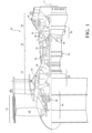
- FIG. 1 schematically illustrates a gas turbine engine 20.
- the gas turbine engine 20 is disclosed herein as a two-spool turbo fan that generally incorporates a fan section 22, a compressor section 24, a combustor section 26 and a turbine section 28.
- the fan section 22 drives air along a bypass flowpath while the compressor section 24 drives air along a core flowpath for compression and communication into the combustor section 26 then expansion through the turbine section 28.
- a turbofan in the disclosed non-limiting embodiment, it should be understood that the concepts described herein are not limited to use with turbofans as the teachings may be applied to other types of turbine engine architectures such as turbojets, turboshafts, and three-spool (plus fan) turbofans.
- the engine 20 generally includes a low spool 30 and a high spool 32 mounted for rotation about an engine central longitudinal axis X relative to an engine static structure 36 via several bearing structures 38.
- the low spool 30 generally includes an inner shaft 40 that interconnects a fan 42, a low pressure compressor (“LPC”) 44 and a low pressure turbine (“LPT”) 46.
- the inner shaft 40 drives the fan 42 directly or through a geared architecture 48 to drive the fan 42 at a lower speed than the low spool 30.
- An exemplary reduction transmission is an epicyclic transmission, namely a planetary or star gear system.
- the high spool 32 includes an outer shaft 50 that interconnects a high pressure compressor (“HPC”) 52 and high pressure turbine (“HPT”) 54.
- a combustor 56 is arranged between the high pressure compressor 52 and the high pressure turbine 54.
- the inner shaft 40 and the outer shaft 50 are concentric and rotate about the engine central longitudinal axis X which is collinear with their longitudinal axes.
- the main engine shafts 40, 50 are supported at a plurality of points by bearing structures 38 within the static structure 36. It should be understood that various bearing structures 38 at various locations may alternatively or additionally be provided.
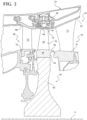
- a full ring shroud assembly 60 within the engine case structure 36 supports a blade outer air seal (BOAS) assembly 62 with a multiple of circumferentially distributed BOAS 64 proximate to a rotor assembly 66 (one schematically shown).
- BOAS blade outer air seal
- the full ring shroud assembly 60 and the BOAS assembly 62 are axially disposed between a forward stationary vane ring 68 and an aft stationary vane ring 70.
- Each vane ring 68, 70 includes an array of vanes 72, 74 that extend between a respective inner vane platform 76, 78 and an outer vane platform 80, 82.
- the outer vane platforms 80, 82 are attached to the engine case structure 36.
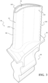
- the rotor assembly 66 includes an array of blades 84 circumferentially disposed around a disk 86.
- Each blade 84 includes a root 88, a platform 90 and an airfoil 92 (also shown in Figure 3 ).
- the blade roots 88 are received within a rim 94 of the disk 86 and the airfoils 92 extend radially outward such that a tip 96 of each airfoil 92 is closest to the blade outer air seal (BOAS) assembly 62.
- the platform 90 separates a gas path side inclusive of the airfoil 92 and a non-gas path side inclusive of the root 88.
- the platform 90 generally separates the root 88 and the airfoil 92 to define an inner boundary of a gas path.
- the airfoil 92 defines a blade chord between a leading edge 98, which may include various forward and/or aft sweep configurations, and a trailing edge 100.
- a first sidewall 102 that may be convex to define a suction side, and a second sidewall 104 that may be concave to define a pressure side are joined at the leading edge 98 and at the axially spaced trailing edge 100.
- the tip 96 extends between the sidewalls 102, 104 opposite the platform 90. It should be appreciated that the tip 96 may include a recessed portion.
- each blade 84 may be formed by casting. It should be appreciated that although a blade 84 with an internal cooling circuit 110 (shown schematically; Figure 4 ) will be described and illustrated in detail, other hot section components including, but not limited to, vanes, turbine shrouds, end walls, and other such components will also benefit here from.
- the internal cooling circuit 110 may include a feed passage 112 that communicates airflow into a trailing edge cavity 114 within the airfoil 84. It should be appreciated that the internal cooling circuit 110 may be of various geometries, and include various features.
- the feed passage 112 in this embodiment is the aft most passage that communicates cooling air to the trailing edge cavity 114.
- the feed passage 112 generally receives cooling flow through at least one inlet 116 within the base 118 of the root 88. It should be appreciated that various feed architecture; cavities, and passageway arrangements will benefit herefrom.
- the tip 96 and the trailing edge 100 bound the trailing edge cavity 114 between the sidewalls 102, 104.
- the trailing edge cavity 114 includes a multiple of features 120.
- the features 120 in this disclosed non-limiting embodiment may include a multiple of pedestals, a multiple of strips, and a multiple of edge features. It should be appreciated that although particular features are delineated within certain general areas, the features may be otherwise arranged or intermingled and still not depart from the disclosure herein.
- a multiple of cooling holes 170 communicates the cooling airflow from the internal cooling circuit 110 through the wall of the blade 84 to provide external film cooling allowing exits of internal cooling flow used in forced convection of the blade.
- one or more of the multiple of cooling holes 170 are shaped cooling holes that include a diffuser shape 172 that may be angled with regard the sidewall 102, 104 of the blade 84 ( Figure 5 ).
- a core 200 is positioned within a shell 202 ( Figure 6 ).
- the shell 202 defines the outer surface of the blade 84 while the core 200 forms the internal surfaces such as that which defines the internal cooling circuit 110 ( Figure 4 ). That is, during the casting process, the core 200 fills a selected volume within the shell 202 that, when removed from the finished blade casting, defines the internal cooling circuit 110 utilized for cooling airflow.
- the shell 202 and the core 200 together define a mold 204 to cast the complex exterior and interior geometries that may be formed of refractory metals, ceramic, or hybrids thereof.
- the mold 204 operates as a melting unit and/or a die for a desired material that forms the blade 84.
- the desired material may include, but not be limited to, a super alloy or other material such as nickel based super alloy, cobalt based super alloy, iron based super alloy, and mixtures thereof that is melted; a molten super alloy that is then solidified; or other material.
- the crucible may be directly filled with a molten super alloy.
- a single crystal starter seed or grain selector may be utilized to enable a single crystal to form when solidifying the component.
- the solidification may utilize a chill block in a directional solidification furnace.
- the directional solidification furnace has a hot zone that may be induction heated and a cold zone separated by an isolation valve.
- the chill block and may be elevated into the hot zone and filled with molten super alloy. After the pour, or being molten, the chill plate may descend into the cold chamber causing a solid/liquid interface to advance from the partially molten starter seed in the form of a single crystallographic oriented component whose orientation is dictated by the orientation of the starter seed. Casting is typically performed under an inert atmosphere or vacuum to preserve the purity of the casting.
- the shell 202 is broken away and the core 200 may be removed from the solidified component by, for example, caustic leaching, to leave the finished single crystal component. After removal, machining, surface treating, coating, or any other desirable finishing operation may be performed to further finish the component.
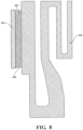
- one disclosed non-limiting embodiment of a method 300 to manufacture the core 200 initially includes manufacture of an additively manufactured skeleton core portion 400 ( Figure 8 ).
- the additively manufactured skeleton core portion 400 may be a semi-finished additively-manufactured extra-resilient skeleton of a refractory metal, such as Molybdenum or aluminum oxide, as well as other materials such as quartz, replete with all the desired cooling hole shapes 402, e.g., showerhead, PS, SS, platform, tip, shapes attached thereto (step 302; Figure 8 and 9 ).
- the cooling hole shapes 402 include a multiple of posts 406 that are positive structure, which, once the shell 202 is broken away and the core 200 removed, form the cooling holes 170 in the blade 84 ( Figure 5 ). That is, the material formed around the cooling hole shapes 402 form the cooling holes 170 once the cooling hole shapes 402 are removed.
- the cooling hole shapes 402 are additively manufactured and integral to the additively manufactured skeleton core portion 400.
- the cooling hole shapes 402 may include external fixation 404 that connect the multiple of cooling hole shapes 402 to provide external support, and thus accurate spacing for each individual cooling hole shape 402. That is, the external fixation 404 facilitates maintenance of cooling hole position by tying together groups of the desired cooling hole shapes 402 and anchoring the desired cooling hole shapes 402 to the shell 202. This may significantly increase accuracy and precision of the cooling holes 170.
- the additively manufactured skeleton core portion 400 is produced with optional finishing steps applied, such as an aluminide coating on the refractory metal. That is, once additively manufactured, the additively manufactured skeleton core portion 400 may be coated or otherwise finished in a manner appropriate for a refractory metal.
- the additively manufactured skeleton core portion 400 with the cooling hole shapes 402 is additively manufactured, the additively manufactured skeleton core portion 400 forms the base of the core 200 that forms internal cooling circuit 110.
- the additively manufactured skeleton core portion 400 and the individual cooling hole shapes 402 may provide more than 50% of the volume of the core 200 to facilitate later removal of the relatively less difficult to remove refractory metal material.
- the additively manufactured skeleton core portion 400 is fixtured or otherwise precisely located within the bed of an additive manufacturing machine (step 304).
- the shape of the additively manufactured skeleton core portion 400 is accounted for in the programming of the additive manufacturing machine (step 306). That is, the programming is utilized to facilitate usage of the additively manufactured skeleton core portion 400 as a reference for the additive manufacturing machine.
- additive manufacturing may be performed on one location of the additively manufactured skeleton core portion 400, then the additively manufactured skeleton core portion 400 is fixtured in another orientation to perform additive manufacturing on another location of the additively manufactured skeleton core portion 400.
- an ceramic material fills the bed, and ceramic printing commences upon or adjacent to the refractory metal additively manufactured skeleton core portion 400 to form an surround core portion 410 that is additively manufactured to the additively manufactured skeleton core portion 400 (step 308A; Figure 8 ).
- the additively manufactured skeleton core portion 400 may be readily manufactured with an additive manufacturing process that includes but are not limited to, Sterolithography (SLA), Direct Selective Laser Sintering (DSLS), Electron Beam Sintering (EBS), Electron Beam Melting (EBM), Laser Engineered Net Shaping (LENS), Laser Net Shape Manufacturing (LNSM), Direct Metal Deposition (DMD), Laser Powder Bed Fusion (LPBF) and others.
- SLA Sterolithography
- DSLS Direct Selective Laser Sintering
- EBS Electron Beam Sintering
- EBM Electron Beam Melting
- LENS Laser Engineered Net Shaping
- LNSM Laser Net Shape Manufacturing
- DMD Direct Metal Deposition
- LPBF Laser Powder Bed Fusion
- the additive material for the surround core portion 410 may be a material different than that of the additively manufactured skeleton core portion 400.
- the surround core portion 410 may be manufactured of silica, alumina ceramic, or other such material to define the internal cooling circuit 110. That is, the additively manufactured skeleton core portion 400 may form the bulk of the core 200 while the surround core portion 410 at least partially encapsulates the additively manufactured skeleton core portion 400 to finalize the shape of the internal cooling circuit 110. It should be appreciated that various and/or multiple additively manufactured surround core portions 410 may be formed.
- the additively manufactured skeleton core portion 400 is inserted into a core die, and a ceramic material is injected around the additively manufactured skeleton core portion 400 while leaving the desired cooling hole shapes 402 exposed (Step 308B). That is, the surround core portion 410 is injection molded rather than additively manufactured. Alternatively, some combination of injection molding is combined with additive manufacturing.
- the additively manufactured skeleton core portion 400 and the surround core portion 410 are then fired to complete the core 200 (step 310). That is, the additively manufactured skeleton core portion 400 and the surround core portion 410 are prepared for final disposition of the core 200 within the shell 202 (step 310).
- wax injection and pattern finishing is the placement of the finished cores plus any quartz rods and support features within the wax die, and injection of the wax around the core which forms the wax pattern. That is, wax pattern finishing is the set of steps to prepare the as-injected wax form for casting, such as wax welding additional features and runners/gates.
- a ceramic and aggregate shell is formed upon the outside of the wax pattern mold (step 314).
- Shelling is typically performed by alternatingly dipping in a wet ceramic slurry and powdering with sand and other agents.
- the wax is removed from within the shell, typically using an autoclave, hence the "lost wax" in the investment casting process (step 316) then the shell is fired (step 318).
- the firing provides for sintering of the shell mold via a high-temperature furnace following drying.
- the workpiece is cast and solidified (step 320).
- the casting is performed via the pouring of a molten alloy into the mold and subsequently controlling the cooling of the alloy between the liquid and solid states, all performed in a vacuum environment.
- step 322 the shell is removed (step 322). That is, the casting is physically knocked-out of the casting from the shell.
- step 324 the application of a heat cycle to the casting in a high-temperature furnace is performed to impart molecular and structural changes to the alloy to achieve desired grain results.
- the core 200 is removed (step 326).
- the bulk of the core 200 is the additively manufactured skeleton core portion 400 which is manufactured of a refractory metal, the time required to remove the core 200 is readily effectuated in days rather week were the entirety of the core manufactured of ceramic (step 328).
- Additive ceramic core cooling holes are not strong enough to repeatably withstand the casting process.
- the method 300 increases yield over a core composed entirely of refractory metal, whether additive, machined, or die-cast, which may suffer from production issues such as recrystallization from being over-stiff and not crushable, and leaching of large section areas will take far longer than a ceramic core.
- refractory metals are much more expensive to be used for large volumes.
- the cooling hole shapes 402 eliminates hole drilling costs and improves the metallurgy surrounding cooling holes, versus laser or EDM by eliminating re-cast layers and heat affected zones.
- the cooling hole shapes 402 also result in a relatively smoother hole finish and shape closer to design intent than EDM or laser hole drilling improves film effectiveness, that may reduce cooling air flow requirements and/or lower part metal temperature.
- the cooling hole shapes 402 also result in more dependable shape and position of cooling holes than EDM or laser hole drilling can reduce flow variability and either tighten manufacturing tolerances or improve process capability. Also, tying the cooling hole shapes 402 together and/or anchoring to the shell with external fixation as part of the skeleton further improve process capability.
Landscapes
- Engineering & Computer Science (AREA)
- Mechanical Engineering (AREA)
- Manufacturing & Machinery (AREA)
- Chemical & Material Sciences (AREA)
- Materials Engineering (AREA)
- Composite Materials (AREA)
- Crystallography & Structural Chemistry (AREA)
- Metallurgy (AREA)
- Organic Chemistry (AREA)
- Physics & Mathematics (AREA)
- Thermal Sciences (AREA)
- Molds, Cores, And Manufacturing Methods Thereof (AREA)
- Turbine Rotor Nozzle Sealing (AREA)
Applications Claiming Priority (2)
| Application Number | Priority Date | Filing Date | Title |
|---|---|---|---|
| US14/976,333 US10226812B2 (en) | 2015-12-21 | 2015-12-21 | Additively manufactured core for use in casting an internal cooling circuit of a gas turbine engine component |
| EP16205980.2A EP3184200A1 (de) | 2015-12-21 | 2016-12-21 | Generativ gefertigter kern zur verwendung beim giessen eines internen kühlkreislaufs einer gasturbinenmotorkomponente |
Related Parent Applications (1)
| Application Number | Title | Priority Date | Filing Date |
|---|---|---|---|
| EP16205980.2A Division EP3184200A1 (de) | 2015-12-21 | 2016-12-21 | Generativ gefertigter kern zur verwendung beim giessen eines internen kühlkreislaufs einer gasturbinenmotorkomponente |
Publications (2)
| Publication Number | Publication Date |
|---|---|
| EP4549152A2 true EP4549152A2 (de) | 2025-05-07 |
| EP4549152A3 EP4549152A3 (de) | 2025-09-24 |
Family
ID=57588852
Family Applications (2)
| Application Number | Title | Priority Date | Filing Date |
|---|---|---|---|
| EP25157212.9A Pending EP4549152A3 (de) | 2015-12-21 | 2016-12-21 | Generativ gefertigter kern zur verwendung beim giessen eines internen kühlkreislaufs einer gasturbinenmotorkomponente |
| EP16205980.2A Withdrawn EP3184200A1 (de) | 2015-12-21 | 2016-12-21 | Generativ gefertigter kern zur verwendung beim giessen eines internen kühlkreislaufs einer gasturbinenmotorkomponente |
Family Applications After (1)
| Application Number | Title | Priority Date | Filing Date |
|---|---|---|---|
| EP16205980.2A Withdrawn EP3184200A1 (de) | 2015-12-21 | 2016-12-21 | Generativ gefertigter kern zur verwendung beim giessen eines internen kühlkreislaufs einer gasturbinenmotorkomponente |
Country Status (2)
| Country | Link |
|---|---|
| US (1) | US10226812B2 (de) |
| EP (2) | EP4549152A3 (de) |
Families Citing this family (9)
| Publication number | Priority date | Publication date | Assignee | Title |
|---|---|---|---|---|
| US10443437B2 (en) * | 2016-11-03 | 2019-10-15 | General Electric Company | Interwoven near surface cooled channels for cooled structures |
| US11420262B2 (en) * | 2018-01-31 | 2022-08-23 | Divergent Technologies, Inc. | Systems and methods for co-casting of additively manufactured interface nodes |
| US11130170B2 (en) | 2018-02-02 | 2021-09-28 | General Electric Company | Integrated casting core-shell structure for making cast component with novel cooling hole architecture |
| US10780498B2 (en) * | 2018-08-22 | 2020-09-22 | General Electric Company | Porous tools and methods of making the same |
| CN111036923A (zh) * | 2019-12-06 | 2020-04-21 | 西安铂力特增材技术股份有限公司 | 结合铸造与选区激光熔化成形制造大型金属零件的方法 |
| DE102019219132A1 (de) * | 2019-12-09 | 2021-06-10 | Volkswagen Aktiengesellschaft | Verfahren und Vorrichtung zur Herstellung eines Gusskerns und ein Verfahren zur Herstellung eines Gussteils sowie ein Kraftfahrzeug |
| US11813665B2 (en) * | 2020-09-14 | 2023-11-14 | General Electric Company | Methods for casting a component having a readily removable casting core |
| CN113084175B (zh) * | 2021-03-16 | 2023-01-24 | 三河市燕郊创新汽车模具有限公司 | 模具复合层材料制备方法及随型冷却模具 |
| CN118439848A (zh) * | 2023-03-13 | 2024-08-06 | 华中科技大学 | 一种热等静压用易溃散高强度复合陶瓷型芯的制备方法 |
Family Cites Families (31)
| Publication number | Priority date | Publication date | Assignee | Title |
|---|---|---|---|---|
| US6974308B2 (en) | 2001-11-14 | 2005-12-13 | Honeywell International, Inc. | High effectiveness cooled turbine vane or blade |
| US6746209B2 (en) | 2002-05-31 | 2004-06-08 | General Electric Company | Methods and apparatus for cooling gas turbine engine nozzle assemblies |
| US6969230B2 (en) | 2002-12-17 | 2005-11-29 | General Electric Company | Venturi outlet turbine airfoil |
| US7014424B2 (en) | 2003-04-08 | 2006-03-21 | United Technologies Corporation | Turbine element |
| US7172012B1 (en) | 2004-07-14 | 2007-02-06 | United Technologies Corporation | Investment casting |
| US7243700B2 (en) * | 2005-10-27 | 2007-07-17 | United Technologies Corporation | Method for casting core removal |
| US7296973B2 (en) | 2005-12-05 | 2007-11-20 | General Electric Company | Parallel serpentine cooled blade |
| US7686065B2 (en) | 2006-05-15 | 2010-03-30 | United Technologies Corporation | Investment casting core assembly |
| US7625178B2 (en) | 2006-08-30 | 2009-12-01 | Honeywell International Inc. | High effectiveness cooled turbine blade |
| US7753104B2 (en) | 2006-10-18 | 2010-07-13 | United Technologies Corporation | Investment casting cores and methods |
| US7806658B2 (en) | 2006-10-25 | 2010-10-05 | Siemens Energy, Inc. | Turbine airfoil cooling system with spanwise equalizer rib |
| US20080131285A1 (en) * | 2006-11-30 | 2008-06-05 | United Technologies Corporation | RMC-defined tip blowing slots for turbine blades |
| US7717676B2 (en) | 2006-12-11 | 2010-05-18 | United Technologies Corporation | High aspect ratio blade main core modifications for peripheral serpentine microcircuits |
| US7610946B2 (en) | 2007-01-05 | 2009-11-03 | Honeywell International Inc. | Cooled turbine blade cast tip recess |
| US8210814B2 (en) | 2008-06-18 | 2012-07-03 | General Electric Company | Crossflow turbine airfoil |
| US8348614B2 (en) | 2008-07-14 | 2013-01-08 | United Technologies Corporation | Coolable airfoil trailing edge passage |
| US8113780B2 (en) | 2008-11-21 | 2012-02-14 | United Technologies Corporation | Castings, casting cores, and methods |
| US8157504B2 (en) | 2009-04-17 | 2012-04-17 | General Electric Company | Rotor blades for turbine engines |
| US8813812B2 (en) * | 2010-02-25 | 2014-08-26 | Siemens Energy, Inc. | Turbine component casting core with high resolution region |
| US20120269649A1 (en) | 2011-04-22 | 2012-10-25 | Christopher Rawlings | Turbine blade with improved trailing edge cooling |
| US20130026338A1 (en) * | 2011-07-28 | 2013-01-31 | Lea Kennard Castle | Rapid casting article manufacturing |
| US8261810B1 (en) | 2012-01-24 | 2012-09-11 | Florida Turbine Technologies, Inc. | Turbine airfoil ceramic core with strain relief slot |
| US9079803B2 (en) | 2012-04-05 | 2015-07-14 | United Technologies Corporation | Additive manufacturing hybrid core |
| US9243502B2 (en) | 2012-04-24 | 2016-01-26 | United Technologies Corporation | Airfoil cooling enhancement and method of making the same |
| US20130280081A1 (en) * | 2012-04-24 | 2013-10-24 | Mark F. Zelesky | Gas turbine engine airfoil geometries and cores for manufacturing process |
| US20140102656A1 (en) * | 2012-10-12 | 2014-04-17 | United Technologies Corporation | Casting Cores and Manufacture Methods |
| US9551228B2 (en) * | 2013-01-09 | 2017-01-24 | United Technologies Corporation | Airfoil and method of making |
| EP2981677A4 (de) * | 2013-04-03 | 2016-06-22 | United Technologies Corp | Hinterkantenhohlraum von variabler dicke und verfahren zur herstellung |
| WO2015009448A1 (en) * | 2013-07-19 | 2015-01-22 | United Technologies Corporation | Additively manufactured core |
| WO2015050987A1 (en) | 2013-10-04 | 2015-04-09 | United Technologies Corporation | Additive manufactured fuel nozzle core for a gas turbine engine |
| CA2885074A1 (en) * | 2014-04-24 | 2015-10-24 | Howmet Corporation | Ceramic casting core made by additive manufacturing |
-
2015
- 2015-12-21 US US14/976,333 patent/US10226812B2/en active Active
-
2016
- 2016-12-21 EP EP25157212.9A patent/EP4549152A3/de active Pending
- 2016-12-21 EP EP16205980.2A patent/EP3184200A1/de not_active Withdrawn
Also Published As
| Publication number | Publication date |
|---|---|
| US20170173671A1 (en) | 2017-06-22 |
| EP3184200A1 (de) | 2017-06-28 |
| US10226812B2 (en) | 2019-03-12 |
| EP4549152A3 (de) | 2025-09-24 |
Similar Documents
| Publication | Publication Date | Title |
|---|---|---|
| US11059093B2 (en) | Additively manufactured core for use in casting an internal cooling circuit of a gas turbine engine component | |
| US10226812B2 (en) | Additively manufactured core for use in casting an internal cooling circuit of a gas turbine engine component | |
| US10570744B2 (en) | Method for forming components using additive manufacturing and re-melt | |
| US11236621B2 (en) | Method for forming single crystal components using additive manufacturing and re-melt | |
| US9770758B2 (en) | Method for forming a directionally solidified replacement body for a component using additive manufacturing | |
| US11268387B2 (en) | Splayed tip features for gas turbine engine airfoil | |
| US9718127B2 (en) | Method for forming components using additive manufacturing and re-melt | |
| EP3021999A1 (de) | Zusätzlich hergestellter kern | |
| WO2014028095A2 (en) | Blade outer air seal with cored passages | |
| US10766065B2 (en) | Method and assembly for a multiple component core assembly | |
| US8074701B2 (en) | Method for producing a pattern for the precision-cast preparation of a component comprising at least one cavity | |
| US20190316474A1 (en) | Cupped contour for gas turbine engine blade assembly | |
| US20080202718A1 (en) | Process For Producing A Lost Model, And Core Introduced Therein | |
| US20190118253A1 (en) | Method for seeding a mold | |
| US20060162893A1 (en) | Method for the production of a casting mold | |
| EP3581293A1 (de) | Verfahren zum giessen von kühllöchern für einen internen kühlkreislauf einer gasturbinentriebwerkskomponente |
Legal Events
| Date | Code | Title | Description |
|---|---|---|---|
| PUAI | Public reference made under article 153(3) epc to a published international application that has entered the european phase |
Free format text: ORIGINAL CODE: 0009012 |
|
| STAA | Information on the status of an ep patent application or granted ep patent |
Free format text: STATUS: THE APPLICATION HAS BEEN PUBLISHED |
|
| AC | Divisional application: reference to earlier application |
Ref document number: 3184200 Country of ref document: EP Kind code of ref document: P |
|
| AK | Designated contracting states |
Kind code of ref document: A2 Designated state(s): AL AT BE BG CH CY CZ DE DK EE ES FI FR GB GR HR HU IE IS IT LI LT LU LV MC MK MT NL NO PL PT RO RS SE SI SK SM TR |
|
| REG | Reference to a national code |
Ref country code: DE Ref legal event code: R079 Free format text: PREVIOUS MAIN CLASS: B33Y0080000000 Ipc: B22C0009100000 |
|
| PUAL | Search report despatched |
Free format text: ORIGINAL CODE: 0009013 |
|
| AK | Designated contracting states |
Kind code of ref document: A3 Designated state(s): AL AT BE BG CH CY CZ DE DK EE ES FI FR GB GR HR HU IE IS IT LI LT LU LV MC MK MT NL NO PL PT RO RS SE SI SK SM TR |
|
| RIC1 | Information provided on ipc code assigned before grant |
Ipc: C30B 1/02 20060101ALI20250821BHEP Ipc: B22C 9/10 20060101AFI20250821BHEP Ipc: B22D 23/06 20060101ALI20250821BHEP Ipc: B22D 27/04 20060101ALI20250821BHEP Ipc: B22F 3/105 20060101ALI20250821BHEP Ipc: B22F 5/00 20060101ALI20250821BHEP Ipc: B22F 7/08 20060101ALI20250821BHEP Ipc: B28B 1/00 20060101ALI20250821BHEP Ipc: B28B 7/34 20060101ALI20250821BHEP Ipc: B33Y 80/00 20150101ALI20250821BHEP Ipc: B22C 9/24 20060101ALI20250821BHEP |