EP4549059A1 - Machine tool, and machine tool alignment method - Google Patents
Machine tool, and machine tool alignment method Download PDFInfo
- Publication number
- EP4549059A1 EP4549059A1 EP22949422.4A EP22949422A EP4549059A1 EP 4549059 A1 EP4549059 A1 EP 4549059A1 EP 22949422 A EP22949422 A EP 22949422A EP 4549059 A1 EP4549059 A1 EP 4549059A1
- Authority
- EP
- European Patent Office
- Prior art keywords
- spindle
- machine tool
- shaft alignment
- variance
- physical quantity
- Prior art date
- Legal status (The legal status is an assumption and is not a legal conclusion. Google has not performed a legal analysis and makes no representation as to the accuracy of the status listed.)
- Pending
Links
Images








Classifications
-
- G—PHYSICS
- G05—CONTROLLING; REGULATING
- G05B—CONTROL OR REGULATING SYSTEMS IN GENERAL; FUNCTIONAL ELEMENTS OF SUCH SYSTEMS; MONITORING OR TESTING ARRANGEMENTS FOR SUCH SYSTEMS OR ELEMENTS
- G05B19/00—Program-control systems
- G05B19/02—Program-control systems electric
- G05B19/18—Numerical control [NC], i.e. automatically operating machines, in particular machine tools, e.g. in a manufacturing environment, so as to execute positioning, movement or co-ordinated operations by means of program data in numerical form
- G05B19/404—Numerical control [NC], i.e. automatically operating machines, in particular machine tools, e.g. in a manufacturing environment, so as to execute positioning, movement or co-ordinated operations by means of program data in numerical form characterised by control arrangements for compensation, e.g. for backlash, overshoot, tool offset, tool wear, temperature, machine construction errors, load, inertia
-
- B—PERFORMING OPERATIONS; TRANSPORTING
- B23—MACHINE TOOLS; METAL-WORKING NOT OTHERWISE PROVIDED FOR
- B23Q—DETAILS, COMPONENTS, OR ACCESSORIES FOR MACHINE TOOLS, e.g. ARRANGEMENTS FOR COPYING OR CONTROLLING; MACHINE TOOLS IN GENERAL CHARACTERISED BY THE CONSTRUCTION OF PARTICULAR DETAILS OR COMPONENTS; COMBINATIONS OR ASSOCIATIONS OF METAL-WORKING MACHINES, NOT DIRECTED TO A PARTICULAR RESULT
- B23Q15/00—Automatic control or regulation of feed movement, cutting velocity or position of tool or work
- B23Q15/007—Automatic control or regulation of feed movement, cutting velocity or position of tool or work while the tool acts upon the workpiece
- B23Q15/12—Adaptive control, i.e. adjusting itself to have a performance which is optimum according to a preassigned criterion
-
- B—PERFORMING OPERATIONS; TRANSPORTING
- B23—MACHINE TOOLS; METAL-WORKING NOT OTHERWISE PROVIDED FOR
- B23Q—DETAILS, COMPONENTS, OR ACCESSORIES FOR MACHINE TOOLS, e.g. ARRANGEMENTS FOR COPYING OR CONTROLLING; MACHINE TOOLS IN GENERAL CHARACTERISED BY THE CONSTRUCTION OF PARTICULAR DETAILS OR COMPONENTS; COMBINATIONS OR ASSOCIATIONS OF METAL-WORKING MACHINES, NOT DIRECTED TO A PARTICULAR RESULT
- B23Q15/00—Automatic control or regulation of feed movement, cutting velocity or position of tool or work
- B23Q15/20—Automatic control or regulation of feed movement, cutting velocity or position of tool or work before or after the tool acts upon the workpiece
- B23Q15/22—Control or regulation of position of tool or workpiece
-
- B—PERFORMING OPERATIONS; TRANSPORTING
- B23—MACHINE TOOLS; METAL-WORKING NOT OTHERWISE PROVIDED FOR
- B23Q—DETAILS, COMPONENTS, OR ACCESSORIES FOR MACHINE TOOLS, e.g. ARRANGEMENTS FOR COPYING OR CONTROLLING; MACHINE TOOLS IN GENERAL CHARACTERISED BY THE CONSTRUCTION OF PARTICULAR DETAILS OR COMPONENTS; COMBINATIONS OR ASSOCIATIONS OF METAL-WORKING MACHINES, NOT DIRECTED TO A PARTICULAR RESULT
- B23Q17/00—Arrangements for observing, indicating or measuring on machine tools
- B23Q17/12—Arrangements for observing, indicating or measuring on machine tools for indicating or measuring vibration
-
- B—PERFORMING OPERATIONS; TRANSPORTING
- B23—MACHINE TOOLS; METAL-WORKING NOT OTHERWISE PROVIDED FOR
- B23B—TURNING; BORING
- B23B25/00—Accessories or auxiliary equipment for turning-machines
- B23B25/06—Measuring, gauging, or adjusting equipment on turning-machines for setting-on, feeding, controlling, or monitoring the cutting tools or work
-
- B—PERFORMING OPERATIONS; TRANSPORTING
- B23—MACHINE TOOLS; METAL-WORKING NOT OTHERWISE PROVIDED FOR
- B23B—TURNING; BORING
- B23B3/00—General-purpose turning-machines or devices, e.g. centre lathes with feed rod and lead screw; Sets of turning-machines
- B23B3/30—Turning-machines with two or more working-spindles, e.g. in fixed arrangement
-
- G—PHYSICS
- G05—CONTROLLING; REGULATING
- G05B—CONTROL OR REGULATING SYSTEMS IN GENERAL; FUNCTIONAL ELEMENTS OF SUCH SYSTEMS; MONITORING OR TESTING ARRANGEMENTS FOR SUCH SYSTEMS OR ELEMENTS
- G05B2219/00—Program-control systems
- G05B2219/30—Nc systems
- G05B2219/37—Measurements
- G05B2219/37434—Measuring vibration of machine or workpiece or tool
-
- G—PHYSICS
- G05—CONTROLLING; REGULATING
- G05B—CONTROL OR REGULATING SYSTEMS IN GENERAL; FUNCTIONAL ELEMENTS OF SUCH SYSTEMS; MONITORING OR TESTING ARRANGEMENTS FOR SUCH SYSTEMS OR ELEMENTS
- G05B2219/00—Program-control systems
- G05B2219/30—Nc systems
- G05B2219/50—Machine tool, machine tool null till machine tool work handling
- G05B2219/50152—Align axis cylinder, tube with rotation axis machine
Definitions
- the present disclosure relates to a machine tool and a machine tool alignment method.
- PTL 1 describes a machine tool that detects abnormalities based on data related to the vibration of a clamp configured to be able to implement fastening and attachment of a workpiece or tool.
- Another known type of machine tool has a main spindle and a tailstock spindle that extend along the same axis.
- the workpiece is held at one end and the other end thereof with the respective clamps of the main spindle and the tailstock spindle.
- the main and tailstock spindles could be axially misaligned from each other (shaft misalignment or misalignment).
- PTL 2 describes correcting an axial misalignment between the main spindle and the tailstock spindle based on data acquired by measurements of the axial center of a rod member held on the main spindle and the axial center of a rod member held on the tailstock spindle opposite the main spindle, the measurement being taken using an outer diameter gauge.
- An object of the present disclosure is to facilitate shaft alignment in machine tools.
- An aspect of the present disclosure is a machine tool comprising:
- Another aspect of the present disclosure is a machine tool alignment method for a machine tool, the machine tool including:
- Yet another aspect of the present disclosure is a program for causing a computer to execute the machine tool alignment method specified above or a storage medium storing this program in a non-temporary manner.
- the present disclosure facilitates shaft alignment in machine tools.
- a machine tool that is one aspect of the present disclosure includes: a first spindle holding one end of a workpiece; a second spindle holding the other end of the workpiece; a sensor detecting a physical quantity related to a vibration during synchronous rotation of the first spindle and the second spindle with the workpiece being held by the first spindle and the second spindle; and a controller performing shaft alignment between the first spindle and the second spindle based on the physical quantity.
- first spindle and second spindle be axially aligned. This is why shaft alignment is performed during the manufacture of machine tools. Even if shaft alignment is performed during the manufacture, the machine tool may sometimes experience a shaft misalignment due to changes over time or depending on operating conditions. Therefore, shaft alignment is sometimes performed before using the machine tool. Namely, the controller performs shaft alignment during manufacture or prior to use of the machine tool.
- the shaft alignment between the first spindle and second spindle is performed while the first and second spindles are holding the same workpiece and rotating in sync.
- the phrase "while rotating in sync" may be any situation where the first and second spindles are rotating synchronously as a result including, for example, a case where the first and second spindles are being controlled to rotate in sync, or a case where the first and second spindles having a mechanism for rotating synchronously are rotating.
- the sensor can be any sensor capable of detecting a physical quantity relating to the vibration that occurs in the first or second spindle such as, for example, a vibration sensor (including an acceleration sensor) or a position sensor.
- Fig. 1 is a diagram illustrating one example of a machine tool according to this embodiment.
- the machine tool 1 includes a first spindle 11 and a first headstock 12 that rotatably supports the first spindle 11.
- the first spindle 11 includes a first clamp 13 operable to fasten and to allow attachment of a workpiece W at one end.
- the machine tool 1 also includes a second spindle 21 extending on the substantially same axial line as that of the first spindle 11 and a second headstock 22 that rotatably supports this second spindle 21.
- the second spindle 21 may be a tailstock spindle.
- the second spindle 21 includes a second clamp 23 operable to fasten and to allow attachment of the workpiece W at the other end.
- An adjustment mechanism 24 is provided between the second spindle 21 and the second headstock 22 for moving the second spindle 21 relative to the second headstock 22.
- the adjustment mechanism 24 is configured to relatively move the second spindle 21 in two directions, for example, along the X axis and the Y axis.
- the adjustment mechanism 24 is configured to include a gear and an actuator to drive this gear, for example.
- the first headstock 12 and the second headstock 22 are fixed on the same structure such as a machine bed 100, for example, so that their relative positions do not change. In Fig.
- the axial direction of the first spindle 11 and second spindle (left and right direction in Fig. 1 ) shall be referred to as the Z-axis direction
- the direction perpendicular to the Z axis and parallel to the top surface of the machine bed 100 (up and down direction in Fig. 1 ) shall be referred to as the Y-axis direction
- the direction perpendicular to the top surface of the machine bed 100 (front and back direction in Fig. 1 ) shall be referred to as the X-axis direction.
- a clamp actuator (not shown) made up of cylinders and pistons, for example, can cause the first clamp 13 and second clamp 23 to fasten the workpiece W.
- the first spindle 11 and second spindle 21 are rotated in sync so that the workpiece W is cut, for example, with a tool.
- the phrase “clamping a workpiece W with the first spindle 11” shall mean clamping the workpiece W with the first clamp 13.
- the phrase “clamping a workpiece W with the second spindle 21” shall mean clamping the workpiece with the second clamp 23.
- a vibration sensor 25 is disposed on the second spindle 21 to measure the vibration of the second spindle 21.
- the vibration sensor 25 may measure the vibration of the second spindle 21 only during the shaft alignment between the first spindle 11 and the second spindle 21, or, it may continuously measure the vibration of the second spindle 21 during the operation of the machine tool 1. The timing of measurement by the vibration sensor 25 may be changed as required.
- the vibration sensor 25 can be disposed anywhere as long as it can measure the vibration of the second clamp 23.
- the vibration sensor 25 may be disposed as close as possible to the second clamp 23, for example.
- an acceleration sensor is used as the vibration sensor 25.
- An acceleration sensor is a sensor capable of measuring acceleration in one direction, for example, the X-axis direction or Y-axis direction shown in Fig. 1 .
- a sensor capable of measuring acceleration in two directions or more may be used.
- the vibration sensor 25 is not limited to an acceleration sensor, and may be a distance sensor or the like, for example. Two or more sensors may be used.
- the phrase "readings of the vibration sensor 25" may refer to either voltages that are the outputs of the vibration sensor 25, or values converted from voltage to represent acceleration or vibration. The conversion is performed by a shaft alignment unit 402 to be described later.
- the machine tool 1 includes a controller 40.
- the controller 40 is a computer that controls the machine tool 1.
- Fig. 2 is a schematic block diagram illustrating one example of the configuration of the machine tool 1 according to this embodiment.
- the controller 40 has a configuration of a common computer.
- the controller 40 includes a processor 41, a main storage unit 42, an auxiliary storage unit 43, an input unit 44, and an output unit 45. These units are interconnected with a bus. Sensors including the vibration sensor 25 are connected to the bus with an interface so that signals from these sensors are input to the controller 40. Also connected to the bus via interfaces are an actuator that rotates the first spindle 11, an actuator that rotates the second spindle 21, an actuator that causes the first clamp 13 to fasten and open, an actuator that causes the second clamp 23 to fasten and open, the adjustment mechanism 24, etc., so that control signals are sent from the controller 40 to these components.
- the processor 41 is a CPU (Central Processing Unit) or a DSP (Digital Signal Processor) and the like.
- the processor 41 controls the machine tool 1 and performs various information processing operations.
- the main storage unit 42 is a RAM (Random Access Memory) or a ROM (Read Only Memory) and the like.
- the auxiliary storage unit 43 is an EPROM (Erasable Programmable ROM), an HDD (Hard Disk Drive), removable media, and so on.
- An operating system (OS) and various programs and tables are stored in the auxiliary storage unit 43.
- the processor 41 loads a program stored in the auxiliary storage unit 43 to a work area of the main storage unit 42 and executes it. Various constituent parts are controlled through the execution of the program.
- the controller 40 thus implements the functions that serve predetermined purposes.
- the displacement in the X-axis direction and the variance have a correlation; the larger the absolute value of displacement in the X-axis direction, the higher the variance.
- shaft alignment between the first spindle 11 and second spindle 21 is performed using this phenomenon. Namely, the shaft alignment between the first spindle 11 and the second spindle 21 is carried out by moving the second spindle 21 in a direction in which the variance of the readings of the vibration sensor 25 reduces.
Landscapes
- Engineering & Computer Science (AREA)
- Mechanical Engineering (AREA)
- Human Computer Interaction (AREA)
- Manufacturing & Machinery (AREA)
- Physics & Mathematics (AREA)
- General Physics & Mathematics (AREA)
- Automation & Control Theory (AREA)
- Automatic Control Of Machine Tools (AREA)
- Numerical Control (AREA)
Abstract
Description
- The present disclosure relates to a machine tool and a machine tool alignment method.
- Machine tools for machining a workpiece (machined object) are known, such as NC milling machines and machining centers. Some machine tools include a clamp configured to be able to implement fastening and attachment of a workpiece or tool, and a spindle that is rotatable with the workpiece or tool being mounted by the clamp or the like. An abnormality such as a cutting chip trapped in the mounting part of the workpiece or tool may affect the precision of the workpiece machining.
- A known conventional technique described in
PTL 1, for example, provides an approach to address this problem.PTL 1 describes a machine tool that detects abnormalities based on data related to the vibration of a clamp configured to be able to implement fastening and attachment of a workpiece or tool. - Another known type of machine tool has a main spindle and a tailstock spindle that extend along the same axis. The workpiece is held at one end and the other end thereof with the respective clamps of the main spindle and the tailstock spindle. In this type of machine tool, the main and tailstock spindles could be axially misaligned from each other (shaft misalignment or misalignment).
- A known conventional technique described in
PTL 2, for example, provides an approach to address this problem.PTL 2 describes correcting an axial misalignment between the main spindle and the tailstock spindle based on data acquired by measurements of the axial center of a rod member held on the main spindle and the axial center of a rod member held on the tailstock spindle opposite the main spindle, the measurement being taken using an outer diameter gauge. -
- [PTL 1]
Japanese Patent Application Publication No. 2020-55051 - [PTL 2]
Japanese Patent Application Publication No. H11-309647 - However, it is desirable to implement the shaft alignment of the main and tailstock spindles much easier.
- An object of the present disclosure is to facilitate shaft alignment in machine tools.
- An aspect of the present disclosure is a machine tool comprising:
- a first spindle holding one end of a workpiece;
- a second spindle holding another end of the workpiece;
- a sensor detecting a physical quantity related to a vibration during synchronous rotation of the first spindle and the second spindle with the workpiece being held by the first spindle and the second spindle; and
- a controller performing shaft alignment between the first spindle and the second spindle based on the physical quantity.
- Another aspect of the present disclosure is a machine tool alignment method for a machine tool, the machine tool including:
- a first spindle holding one end of a workpiece;
- a second spindle holding another end of the workpiece;
- a sensor detecting a physical quantity related to a vibration during synchronous rotation of the first spindle and the second spindle with the workpiece being held by the first spindle and the second spindle; and
- a controller performing shaft alignment between the first spindle and the second spindle based on the physical quantity.
- Yet another aspect of the present disclosure is a program for causing a computer to execute the machine tool alignment method specified above or a storage medium storing this program in a non-temporary manner.
- The present disclosure facilitates shaft alignment in machine tools.
-
- [
Fig. 1 ]
Fig. 1 is a diagram illustrating one example of a machine tool according to an embodiment. - [
Fig. 2 ]
Fig. 2 is a schematic block diagram illustrating one example of the configuration of the machine tool according to the embodiment. - [
Fig. 3 ]
Fig. 3 is a diagram illustrating one example of the functional configuration of a controller. - [
Fig. 4 ]
Fig. 4 is a time chart showing vibration sensor readings before and after a workpiece is fastened. - [
Fig. 5 ]
Fig. 5 is a diagram showing the empirically obtained variance of the vibration sensor readings in a case where a second spindle is intentionally displaced relative to a first spindle. - [
Fig. 6 ]
Fig. 6 is a diagram illustrating an example of the moving track of the second spindle during the shaft alignment between the first spindle and the second spindle. - [
Fig. 7 ]
Fig. 7 is a diagram showing an example of variance of the vibration sensor readings in a case where the second spindle is moving along the track shown inFig. 6 . - [
Fig. 8 ]
Fig. 8 is a diagram illustrating an example of the moving track of the second spindle in the direction toward a first angular position during the shaft alignment between the first spindle and the second spindle. - [
Fig. 9 ]
Fig. 9 is a diagram showing an example of variance of the vibration sensor readings in a case where the second spindle is moving along the track shown inFig. 8 . - [
Fig. 10 ]
Fig. 10 is a diagram illustrating an example of the moving track of the second spindle starting from (X1, Y1) during the shaft alignment between the first spindle and the second spindle. - [
Fig. 11 ]
Fig. 11 is a diagram showing an example of variance of the vibration sensor readings in a case where the second spindle is moving along the track shown inFig. 10 . - [
Fig. 12 ]
Fig. 12 is a flowchart illustrating the process flow of shaft alignment between the first spindle and the second spindle. - [
Fig. 13 ]
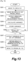
Fig. 13 is a flowchart illustrating the process flow of a circular motion process. - [
Fig. 14 ]
Fig. 14 is a flowchart illustrating the process flow of a linear motion process. - [
Fig. 15 ]
Fig. 15 is a diagram showing the empirically obtained range of vibration sensor readings in a case where the second spindle is intentionally displaced relative to the first spindle. - A machine tool that is one aspect of the present disclosure includes: a first spindle holding one end of a workpiece; a second spindle holding the other end of the workpiece; a sensor detecting a physical quantity related to a vibration during synchronous rotation of the first spindle and the second spindle with the workpiece being held by the first spindle and the second spindle; and a controller performing shaft alignment between the first spindle and the second spindle based on the physical quantity.
- When rotating the first and second spindles holding the workpiece in sync, it is desirable that the first spindle and second spindle be axially aligned. This is why shaft alignment is performed during the manufacture of machine tools. Even if shaft alignment is performed during the manufacture, the machine tool may sometimes experience a shaft misalignment due to changes over time or depending on operating conditions. Therefore, shaft alignment is sometimes performed before using the machine tool. Namely, the controller performs shaft alignment during manufacture or prior to use of the machine tool.
- The shaft alignment between the first spindle and second spindle is performed while the first and second spindles are holding the same workpiece and rotating in sync. The phrase "while rotating in sync" may be any situation where the first and second spindles are rotating synchronously as a result including, for example, a case where the first and second spindles are being controlled to rotate in sync, or a case where the first and second spindles having a mechanism for rotating synchronously are rotating. When the first and second spindles are rotating in sync as described above, if the first and second spindles are axially misaligned, vibration occurs either in the first or second spindle. Therefore, it can be determined whether the first and second spindles are axially aligned based on this vibration. The controller performs shaft alignment based on this vibration.
- The sensor can be any sensor capable of detecting a physical quantity relating to the vibration that occurs in the first or second spindle such as, for example, a vibration sensor (including an acceleration sensor) or a position sensor.
- Embodiments of the present disclosure will be hereinafter described with reference to the drawings. It should be noted that, unless otherwise specified, the sizes, materials, shapes, and relative arrangement or the like of constituent components described in the embodiments are not intended to limit the scope of this disclosure.
-
Fig. 1 is a diagram illustrating one example of a machine tool according to this embodiment. As shown inFig. 1 , themachine tool 1 according to this embodiment includes afirst spindle 11 and afirst headstock 12 that rotatably supports thefirst spindle 11. Thefirst spindle 11 includes afirst clamp 13 operable to fasten and to allow attachment of a workpiece W at one end. Themachine tool 1 also includes asecond spindle 21 extending on the substantially same axial line as that of thefirst spindle 11 and asecond headstock 22 that rotatably supports thissecond spindle 21. Thesecond spindle 21 may be a tailstock spindle. Thesecond spindle 21 includes asecond clamp 23 operable to fasten and to allow attachment of the workpiece W at the other end. Anadjustment mechanism 24 is provided between thesecond spindle 21 and thesecond headstock 22 for moving thesecond spindle 21 relative to thesecond headstock 22. Theadjustment mechanism 24 is configured to relatively move thesecond spindle 21 in two directions, for example, along the X axis and the Y axis. Theadjustment mechanism 24 is configured to include a gear and an actuator to drive this gear, for example. Thefirst headstock 12 and thesecond headstock 22 are fixed on the same structure such as amachine bed 100, for example, so that their relative positions do not change. InFig. 1 , the axial direction of thefirst spindle 11 and second spindle (left and right direction inFig. 1 ) shall be referred to as the Z-axis direction, the direction perpendicular to the Z axis and parallel to the top surface of the machine bed 100 (up and down direction inFig. 1 ) shall be referred to as the Y-axis direction, and the direction perpendicular to the top surface of the machine bed 100 (front and back direction inFig. 1 ) shall be referred to as the X-axis direction. - A clamp actuator (not shown) made up of cylinders and pistons, for example, can cause the
first clamp 13 andsecond clamp 23 to fasten the workpiece W. With thefirst clamp 13 andsecond clamp 23 fastening the workpiece W, thefirst spindle 11 andsecond spindle 21 are rotated in sync so that the workpiece W is cut, for example, with a tool. Hereinafter, the phrase "clamping a workpiece W with thefirst spindle 11" shall mean clamping the workpiece W with thefirst clamp 13. Likewise, the phrase "clamping a workpiece W with thesecond spindle 21" shall mean clamping the workpiece with thesecond clamp 23. - A
vibration sensor 25 is disposed on thesecond spindle 21 to measure the vibration of thesecond spindle 21. Thevibration sensor 25 may measure the vibration of thesecond spindle 21 only during the shaft alignment between thefirst spindle 11 and thesecond spindle 21, or, it may continuously measure the vibration of thesecond spindle 21 during the operation of themachine tool 1. The timing of measurement by thevibration sensor 25 may be changed as required. Thevibration sensor 25 can be disposed anywhere as long as it can measure the vibration of thesecond clamp 23. Thevibration sensor 25 may be disposed as close as possible to thesecond clamp 23, for example. In this embodiment, an acceleration sensor is used as thevibration sensor 25. An acceleration sensor is a sensor capable of measuring acceleration in one direction, for example, the X-axis direction or Y-axis direction shown inFig. 1 . As an alternative, a sensor capable of measuring acceleration in two directions or more may be used. Thevibration sensor 25 is not limited to an acceleration sensor, and may be a distance sensor or the like, for example. Two or more sensors may be used. Hereinafter, the phrase "readings of thevibration sensor 25" may refer to either voltages that are the outputs of thevibration sensor 25, or values converted from voltage to represent acceleration or vibration. The conversion is performed by ashaft alignment unit 402 to be described later. - The
machine tool 1 includes acontroller 40. Thecontroller 40 is a computer that controls themachine tool 1.Fig. 2 is a schematic block diagram illustrating one example of the configuration of themachine tool 1 according to this embodiment. - The
controller 40 has a configuration of a common computer. Thecontroller 40 includes aprocessor 41, amain storage unit 42, anauxiliary storage unit 43, aninput unit 44, and anoutput unit 45. These units are interconnected with a bus. Sensors including thevibration sensor 25 are connected to the bus with an interface so that signals from these sensors are input to thecontroller 40. Also connected to the bus via interfaces are an actuator that rotates thefirst spindle 11, an actuator that rotates thesecond spindle 21, an actuator that causes thefirst clamp 13 to fasten and open, an actuator that causes thesecond clamp 23 to fasten and open, theadjustment mechanism 24, etc., so that control signals are sent from thecontroller 40 to these components. - The
processor 41 is a CPU (Central Processing Unit) or a DSP (Digital Signal Processor) and the like. Theprocessor 41 controls themachine tool 1 and performs various information processing operations. Themain storage unit 42 is a RAM (Random Access Memory) or a ROM (Read Only Memory) and the like. Theauxiliary storage unit 43 is an EPROM (Erasable Programmable ROM), an HDD (Hard Disk Drive), removable media, and so on. An operating system (OS) and various programs and tables are stored in theauxiliary storage unit 43. Theprocessor 41 loads a program stored in theauxiliary storage unit 43 to a work area of themain storage unit 42 and executes it. Various constituent parts are controlled through the execution of the program. Thecontroller 40 thus implements the functions that serve predetermined purposes. Themain storage unit 42 andauxiliary storage unit 43 are computer-readable recording media. Thecontroller 40 may be a single computer, or a plurality of computers coordinated to work together. The information stored in theauxiliary storage unit 43 may be stored in themain storage unit 42. The information stored in themain storage unit 42 may be stored in theauxiliary storage unit 43. - The
input unit 44 includes means for receiving input operations performed by a user, such as a touchscreen, a mouse, a keyboard, or a microphone. Theoutput unit 45 includes means that present information to the user, such as an LCD (Liquid Crystal Display), an EL (Electroluminescence) panel, a speaker, and a lamp. Theinput unit 44 andoutput unit 45 can be configured as one touchscreen display. -
Fig. 3 is a diagram illustrating one example of the functional configuration of thecontroller 40. Thecontroller 40 includes amachining control unit 401 and ashaft alignment unit 402 as functional constituent elements. Themachining control unit 401 andshaft alignment unit 402 are functional constituent elements provided by theprocessor 41 of thecontroller 40, for example, executing various programs stored in theauxiliary storage unit 43. - The
machining control unit 401 controls themachine tool 1 during the machining of a workpiece W. Themachining control unit 401 causes thefirst clamp 13 andsecond clamp 23 to fasten the workpiece W, rotates thefirst spindle 11 andsecond spindle 21 in sync, and controls the movement of the tool, to cut the workpiece W, for example. Any known techniques can be used for the machining control of the workpiece W by themachining control unit 401. - The
shaft alignment unit 402 performs shaft alignment (alignment of shaft centers) between thefirst spindle 11 andsecond spindle 21 based on the readings of thevibration sensor 25. Theshaft alignment unit 402 performs shaft alignment before the machining control of the workpiece W by themachining control unit 401, for example. Now, the relationship between the readings of thevibration sensor 25 and the axial misalignment between thefirst spindle 11 andsecond spindle 21 is explained with reference toFig. 4 andFig. 5 . -
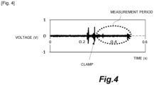
Fig. 4 is a time chart showing the readings of thevibration sensor 25 before and after a workpiece W is fastened. The horizontal axis and vertical axis inFig. 4 represent the time and the voltage output of thevibration sensor 25, respectively. When time is 0 inFig. 4 , one end of the workpiece W is clamped by thefirst clamp 13 alone, and thefirst spindle 11, workpiece W, andsecond spindle 21 are rotating in sync. The other end of the workpiece W is clamped by thesecond clamp 23 after that. When thesecond spindle 21 clamps the workpiece W, thevibration sensor 25 detects the vibration that occurs at this time. The vibration caused by this clamping is indicated with the word "clamp" inFig. 4 . After that, thefirst spindle 11 andsecond spindle 21 continue to rotate in sync with the workpiece W held on both ends by thefirst spindle 11 andsecond spindle 21. - The variance of the values detected by the
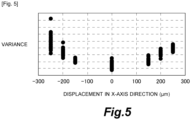
vibration sensor 25 after the vibration caused by the clamping has sufficiently decreased is correlated to the degree of axial misalignment between thefirst spindle 11 and thesecond spindle 21.Fig. 5 is a diagram showing the empirically obtained variance of the readings of thevibration sensor 25 when thesecond spindle 21 is intentionally displaced relative to thefirst spindle 11. The horizontal axis inFig. 5 represents the displacement in the X-axis direction of thesecond spindle 21 relative to thefirst spindle 11. The X axis referred to inFig. 5 corresponds to the X axis as defined inFig. 1 . There is no displacement in the Y-axis direction.Fig. 5 plots the variance that was determined several times for each amount of displacement. The variances inFig. 5 are those of the values detected by thevibration sensor 25 during the period denoted as "measurement period" inFig. 4 . The measurement period inFig. 4 is a period after the vibration caused by the clamping has sufficiently decreased, and long enough for the measurement of the variance. Hereinafter, the term "variance" shall refer to the variance of the readings of thevibration sensor 25. - As shown in
Fig. 5 , the displacement in the X-axis direction and the variance have a correlation; the larger the absolute value of displacement in the X-axis direction, the higher the variance. In the present disclosure, shaft alignment between thefirst spindle 11 andsecond spindle 21 is performed using this phenomenon. Namely, the shaft alignment between thefirst spindle 11 and thesecond spindle 21 is carried out by moving thesecond spindle 21 in a direction in which the variance of the readings of thevibration sensor 25 reduces. - Next, the control that is executed when the shaft alignment between the
first spindle 11 and thesecond spindle 21 is performed in this embodiment will be described. Theshaft alignment unit 402 performs the shaft alignment between thefirst spindle 11 and thesecond spindle 21 with thefirst spindle 11 andsecond spindle 21 both holding the same workpiece W and rotating in the same direction at the same rotation speed (i.e., rotating in sync). Theshaft alignment unit 402 performs the shaft alignment after the vibration caused by the fastening of the workpiece W has reduced sufficiently to avoid adverse effects of the vibration. The shaft alignment can be performed only once during the manufacture of themachine tool 1, or every time themachine tool 1 is started, or every time a workpiece W is fastened. -
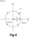
Fig. 6 is a diagram illustrating an example of the moving track of thesecond spindle 21 during the shaft alignment between thefirst spindle 11 and thesecond spindle 21. The X axis and Y axis inFig. 6 correspond respectively to the X axis and Y axis inFig. 1 . InFig. 6 , the coordinates of the origin, which is the starting point of thesecond spindle 21, is shown by (X0, Y0). The origin is the position of the center axis of thesecond spindle 21 when thesecond spindle 21 has fastened the workpiece W. Theshaft alignment unit 402 moves thesecond spindle 21 along a circle S1 having the origin (X0, Y0) as the center. The diameter of the circle S1 can be set to any suitable value not greater than the maximum value of an axial misalignment between thefirst spindle 11 and thesecond spindle 21 due to manufacturing tolerances, for example. Namely, even if there is an axial misalignment between thefirst spindle 11 and thesecond spindle 21, it is assumed to be within the range of manufacturing tolerances. Therefore, thesecond spindle 21 is moved within this range to find the position where it is axially aligned. - The
shaft alignment unit 402 carries out the following steps in the shaft alignment process. Numbers (1) to (3) below respectively correspond to arrows (1) to (3) shown inFig. 6 . - (1) First, the
shaft alignment unit 402 generates a command to move thesecond spindle 21 in the X-axis direction to (XA, Y0). The readings of thevibration sensor 25 at this time are not used. Position (XA, Y0) is the intersection of the X axis and the circle S1. Position (XA, Y0), or the diameter radius of the circle S1, is stored in theauxiliary storage unit 43 in advance. Theshaft alignment unit 402 sends the generated command to theadjustment mechanism 24, which moves thesecond spindle 21 based on this command. When the current position of thesecond spindle 21 reaches position (XA, Y0), theshaft alignment unit 402 stops thesecond spindle 21. The current position of thesecond spindle 21 may be detected using a sensor, for example, or may be determined by calculation based on the amount of movement of theadjustment mechanism 24. - (2) Next, the
shaft alignment unit 402 generates a command to move thesecond spindle 21 along the circle S1. While thesecond spindle 21 is moved counterclockwise inFig. 6 , it may be moved clockwise. The readings of thevibration sensor 25 are obtained, for example, at each preset angular position around the origin (X0, Y0). In this case, theshaft alignment unit 402 stops thesecond spindle 21 at each preset angular position throughout a measurement period and obtains the readings of thevibration sensor 25 throughout the measurement period. Therefore, theshaft alignment unit 402 generates a command for moving thesecond spindle 21 along the circle S1 and a command for stopping thesecond spindle 21 at each preset angular position throughout the measurement period, and sends these commands to theadjustment mechanism 24. Theadjustment mechanism 24 moves thesecond spindle 21 based on these commands.
The measurement period is preset to be a period that allows accurate calculation of the variance corresponding to a shaft misalignment. Theshaft alignment unit 402 stores the readings of thevibration sensor 25 obtained throughout the measurement period at each preset angular position in theauxiliary storage unit 43 associating them with the angular positions around the origin (X0, Y0). Moreover, theshaft alignment unit 402 calculates the variance of the readings of thevibration sensor 25 based on the readings of thevibration sensor 25 obtained throughout the measurement period and stores the variance in theauxiliary storage unit 43 associating it with the angular position around the origin (X0, Y0). The angular positions may be set based on the time required for the shaft alignment and the accuracy of the shaft alignment, for example. The smaller the angle between angular positions, the more accurate the shaft alignment will be, although it will take more time for the shaft alignment. The angle may therefore be determined by the user based on which of the time and the accuracy should be given priority. For example, a preset angular position may be input from theinput unit 44. - (3) When the
second spindle 21 returns to position (XA, Y0), theshaft alignment unit 402 stops the detection of vibration by thevibration sensor 25 and generates a command to move thesecond spindle 21 to the origin (X0, Y0). Theshaft alignment unit 402 sends the generated command to theadjustment mechanism 24, which moves thesecond spindle 21 to the origin (X0, Y0) based on this command. -
Fig. 7 is a diagram showing an example of variance of the readings of thevibration sensor 25 in a case where thesecond spindle 21 is moving along the track shown inFig. 6 . The horizontal axis represents the angular position around the origin (X0, Y0) with 0 being the angular position when thesecond spindle 21 is at position (XA, Y0). In the example shown inFig. 7 , the variance reduces as the angle increases from 0 and reaches the minimum value denoted by B1 at angular position A1. The variance increases as the angle increases from A1. Hereinafter, the angle denoted by A1 will be referred to also as first angular position A1. The position on the circle S1 where the variance is minimum corresponds to a first target position according to the present disclosure. - In the example shown in
Fig. 7 , the variance is minimum at the first angular position A1. This means that moving thesecond spindle 21 from the origin (X0, Y0) toward the first angular position A1 can decrease the variance. Namely, the misalignment between thefirst spindle 11 andsecond spindle 21 can be reduced. - Accordingly, the
shaft alignment unit 402 searches for a position where the variance becomes even lower while moving thesecond spindle 21 toward the first angular position A1.Fig. 8 is a diagram illustrating an example of the moving track of thesecond spindle 21 toward the first angular position A1 during the shaft alignment between thefirst spindle 11 and thesecond spindle 21. The origin (X0, Y0) inFig. 8 is at the same position as the origin (X0, Y0) shown inFig. 6 . - The
shaft alignment unit 402 moves thesecond spindle 21 from the origin (X0, Y0) along a straight line L1 extending toward the first angular position A1. For this, theshaft alignment unit 402 carries out the following steps. Numbers (4) and (5) below respectively correspond to arrows (4) and (5) shown inFig. 8 . - (4) The
shaft alignment unit 402 generates a command to move thesecond spindle 21 along the straight line L1 away from the origin (X0, Y0). The readings of thevibration sensor 25 are obtained, for example, at each preset distance from the origin (X0, Y0). In this case, theshaft alignment unit 402 stops thesecond spindle 21 at each preset distance throughout a measurement period and obtains the readings of thevibration sensor 25 throughout the measurement period. Therefore, theshaft alignment unit 402 generates a command for moving thesecond spindle 21 along the straight line L1 and a command for stopping thesecond spindle 21 at each preset distance throughout the measurement period, and sends these commands to theadjustment mechanism 24. Theadjustment mechanism 24 moves thesecond spindle 21 based on these commands. - The
shaft alignment unit 402 stores the readings of thevibration sensor 25 obtained at each preset distance throughout the measurement period in theauxiliary storage unit 43 associating them with the distances from the origin (X0, Y0). Moreover, theshaft alignment unit 402 calculates the variance of the readings of thevibration sensor 25 based on the readings of thevibration sensor 25 obtained throughout the measurement period and stores the variance in theauxiliary storage unit 43 associating it with the distance from the origin (X0, Y0). The distance may be set based on the time required for the shaft alignment and the accuracy of the shaft alignment, for example. The shorter the preset distance, the more accurate the shaft alignment will be, although it will take more time for the shaft alignment. The distance may therefore be determined by the user based on which of the time and the accuracy should be given priority. For example, a preset distance may be input from theinput unit 44. - (5) When the trend of the variance switches from decreasing to increasing, the
shaft alignment unit 402 generates a command to move thesecond spindle 21 toward a second origin (X1, Y1) where the variance is minimum in search of this second origin (X1, Y1). Theshaft alignment unit 402 compares a variance stored in theauxiliary storage unit 43 with the previous and subsequent ones to determine the variance B2 at which the trend switches from decreasing to increasing, and computes the distance A2 from the origin (X0, Y0) corresponding to this variance B2. The position (X1, Y1) of thesecond spindle 21 after it has moved this distance A2 is determined by calculating X1 = A2·cosA1 and Y1 = A2·sinA1. This position (X1, Y1) will be hereinafter referred to also as the second origin (X1, Y1). The second origin (X1, Y1) is the position away from the origin (X0, Y0) by distance A2 in the direction of the first angular position A1. Theshaft alignment unit 402 sends the generated command to theadjustment mechanism 24, which moves thesecond spindle 21 to the second origin (X1, Y1) based on this command. The position on the straight line L1 where the variance is minimum corresponds to a second target position according to the present disclosure. -
Fig. 9 is a diagram showing an example of variance of the readings of thevibration sensor 25 when thesecond spindle 21 is moving along the track shown inFig. 8 . The horizontal axis represents the distance from the origin (X0, Y0). Numbers (4) and (5) shown inFig. 9 respectively correspond to numbers (4) and (5) shown inFig. 8 . In the example shown inFig. 9 , the variance reduces as the distance increases from 0, and reaches the minimum value denoted by B2 when the distance is A2. The variance increases as the distance increases from A2. As shown, the variance becomes minimum at B2 when the distance is A2. - The second origin (X1, Y1) is the position away from the origin (X0, Y0) by a distance at which the variance becomes lowest in a direction of an angular position in which the variance of the readings of the
vibration sensor 25 becomes minimum. At such a second origin (X1, Y1), the variance of the readings of thevibration sensor 25 is lower as compared to the origin (X0, Y0). The position where the variance of the readings of thevibration sensor 25 is lowest possible can be searched for in this way. - When the
first spindle 11 andsecond spindle 21 are axially aligned, the variance B2 of the readings of thevibration sensor 25 at the second origin (X1, Y1) becomes substantially low. On the other hand, there may still remain an axial misalignment between thefirst spindle 11 and thesecond spindle 21. In this case, there is a position where the variance of the readings of thevibration sensor 25 is even lower. Therefore, theshaft alignment unit 402 performs the control steps (1) to (5) described above again starting from the second origin (X1, Y1). By repeating this control in the manner described above, the position of thesecond spindle 21 where the variance of the readings of thevibration sensor 25 becomes even lower can be determined. -
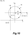
Fig. 10 is a diagram illustrating an example of the moving track of thesecond spindle 21 starting from (X1, Y1) during the shaft alignment between thefirst spindle 11 and thesecond spindle 21. InFig. 10 , the coordinates of the starting point of thesecond spindle 21 are those of the second origin (X1, Y1). The second limit (X1, Y1) is the origin of the X'Y' coordinate system. The second origin (X1, Y1) that is the starting point inFig. 10 is at the same position as the second origin (X1, Y1) inFig. 8 . Theshaft alignment unit 402 moves thesecond spindle 21 along a circle S2 having the second origin (X1, Y1) as the center. The circle S2 has the same diameter as the circle S1 shown inFig. 6 . Alternatively, the circle S2 may have a smaller diameter than the circle S1. - Similarly to the steps described with reference to
Fig. 6 , theshaft alignment unit 402 carries out the following steps. Numbers (6) to (8) below respectively correspond to arrows (6) to (8) shown inFig. 10 . - (6) First, the
shaft alignment unit 402 generates a command to move thesecond spindle 21 in the X'-axis direction to (X1 + XA, Y1). The readings of thevibration sensor 25 at this time are not used. Theshaft alignment unit 402 sends the generated command to theadjustment mechanism 24, which moves thesecond spindle 21 based on this command. - (7) Next, the
shaft alignment unit 402 generates a command to move thesecond spindle 21 along the circle S2. The readings of thevibration sensor 25 are obtained, for example, at each preset angular position around the second origin (X1, Y1). In this case, theshaft alignment unit 402 stops thesecond spindle 21 at each preset angular position throughout a measurement period and obtains the readings of thevibration sensor 25 throughout the measurement period. Therefore, theshaft alignment unit 402 generates a command for moving thesecond spindle 21 along the circle S2 and a command for stopping thesecond spindle 21 at each preset angular position throughout the measurement period, and sends these commands to theadjustment mechanism 24. Theadjustment mechanism 24 moves thesecond spindle 21 based on these commands. - The measurement period is the same as the one described with reference to
Fig. 6 . Theshaft alignment unit 402 stores the readings of thevibration sensor 25 obtained throughout the measurement period at each preset angular position in theauxiliary storage unit 43 associating them with the angular positions around the second origin (X1, Y1). Moreover, theshaft alignment unit 402 calculates the variance of the readings of thevibration sensor 25 based on the readings of thevibration sensor 25 obtained throughout the measurement period and stores the variance in theauxiliary storage unit 43 associating it with the angular position around the second origin (X1, Y1). The preset angular position is the same as the one described with reference toFig. 6 . Alternatively, different angular positions from those described with reference toFig. 6 may be adopted. - (8) When the
second spindle 21 returns to position (X1 + XA, Y1), theshaft alignment unit 402 stops the detection of vibration by thevibration sensor 25 and generates a command to move thesecond spindle 21 to the second origin (X1, Y1). Theshaft alignment unit 402 sends the generated command to theadjustment mechanism 24, which moves thesecond spindle 21 to the second origin (X1, Y1) based on this command. -
Fig. 11 is a diagram showing an example of variance of the readings of thevibration sensor 25 when thesecond spindle 21 is moving along the track shown inFig. 10 . The horizontal axis represents the angular position around the second origin (X1, Y1) with 0 being the angular position when thesecond spindle 21 is at position (X1 + XA, Y1). In the example shown inFig. 11 , the variance reduces as the angle increases from 0 and reaches the minimum value denoted by B3 at angular position A3. The variance increases as the angle increases from A3. Hereinafter, the angle denoted by A3 will be referred to also as second angular position A3. The position on the circle S2 where the variance is minimum also corresponds to the first target position according to the present disclosure. - In the example shown in
Fig. 11 , the variance is minimum at second angular position A3. This means that moving thesecond spindle 21 from the second origin (X1, Y1) of the second angular position A3 can decrease the variance. Namely, it can reduce the axial misalignment between thefirst spindle 11 andsecond spindle 21. In this case, the position where the variance will become even lower can be searched by carrying out the same process as the one described with reference toFig. 8 andFig. 9 . Here, the same process is carried out repeatedly, with the X' axis and Y' axis being replaced with the X axis and Y axis. - On the other hand, when the
first spindle 11 andsecond spindle 21 are axially aligned near the second origin (X1, Y1), moving thesecond spindle 21 away from the second origin (X1, Y1) will increase the axial misalignment, which in turn can increase the variance. In this case, the minimum value B3 of the variance shown inFig. 11 will be equal to or greater than the minimum value B2 of the variance shown inFig. 9 . Therefore, if the minimum value B3 of the variance shown inFig. 11 is equal to or greater than the minimum value B2 of the variance shown inFig. 9 , it is assumed that there is no need to further shift thesecond spindle 21 to another position. Therefore, in this embodiment, when the minimum value B3 of the variance shown inFig. 11 is equal to or greater than the minimum value B2 of the variance shown inFig. 9 , it is determined that the shaft alignment between thefirst spindle 11 andsecond spindle 21 is complete there at the second origin (X1, Y1). - As described above, the position where the variance is even lower can be found by alternately repeating the steps of moving the
second spindle 21 along the circle S1 for an angular position where the variance becomes minimum, and moving thesecond spindle 21 along the straight line L1 for a position where the variance becomes minimum. Thus thefirst spindle 11 andsecond spindle 21 can be axially aligned. - When the shaft alignment between the
first spindle 11 and thesecond spindle 21 is complete, theshaft alignment unit 402 updates the origin of thesecond spindle 21 to the second origin (X1, Y1). At this point, thesecond spindle 21 is positioned at the second origin (X1, Y1). Therefore, the machining control by themachining control unit 401 is started from there with thesecond spindle 21 staying at the same position. - Next, the process flow of shaft alignment between the
first spindle 11 and thesecond spindle 21 in this embodiment will be described.Fig. 12 is a flowchart illustrating the process flow of shaft alignment between thefirst spindle 11 andsecond spindle 21. This routine is carried out before the machining control by themachining control unit 401 is started in themachine tool 1. For example, the routine may be triggered by an input made by a user to theinput unit 44 for starting the machining control. Alternatively, this routine may be carried out during the manufacture of themachine tool 1, or, when the user has started themachine tool 1 based on an input made by the user to theinput unit 44. Alternatively, the routine can be carried out at a certain interval of time, or every time themachine tool 1 has been started a specified number of times. - At step S101, the
shaft alignment unit 402 carries out a fastening step. The fastening step is a process of holding one and the other end of the workpiece W with thefirst spindle 11 and thesecond spindle 21, respectively, and rotating the spindles in sync. In this embodiment, thefirst spindle 11 is rotated at a preset rotation speed with thefirst spindle 11 clamping one end of the workpiece W. Thesecond spindle 21, while being rotated in sync with thefirst spindle 11, then clamps the other end of the workpiece W. - At step S102, the
shaft alignment unit 402 determines whether or not a preset time has elapsed since the completion of the fastening of the workpiece W by thesecond spindle 21. The preset time here means the time it takes for the vibration caused by the fastening of the workpiece W to reduce sufficiently, for example. When the determination at step S102 is affirmative, the process goes to step S103, and when the determination is negative, the process of step S102 is repeated. - At step S103, the
shaft alignment unit 402 obtains the origin of thesecond spindle 21. The origin here refers to either the position of thesecond spindle 21 at the time when the fastening was completed at step S101, the origin (X0, Y0) set at step S310 to be described later, or the origin (X0, Y0) updated at step S106 in the previous run of the routine. - At step S104, the
shaft alignment unit 402 carries out a circular motion process. The circular motion process is a process of acquiring the variance of readings of thevibration sensor 25 at several locations while moving thesecond spindle 21 along a circle S1 as described with reference toFig. 6 .Fig. 13 is a flowchart illustrating the process flow of the circular motion process. The process shown inFig. 13 is a sub-routine executed at step S104. The circular motion process, when performed for the first time, is a process of determining the minimum value B1 of the variance shown inFig. 7 , and from the second time, is a process of determining the minimum value B3 of the variance shown inFig. 11 . - At step S201, the
shaft alignment unit 402 moves thesecond spindle 21 to the circle S1. Theshaft alignment unit 402 generates a command to move thesecond spindle 21 to the circle S1 and sends it to theadjustment mechanism 24. At step S202, theshaft alignment unit 402 moves thesecond spindle 21 on the circle S1 by a preset angle. Theshaft alignment unit 402 generates a command to move thesecond spindle 21 on the circle S1 by a preset angle relative to thesecond headstock 22 and sends it to theadjustment mechanism 24. - At step S203, the
shaft alignment unit 402 detects vibration by obtaining readings of thevibration sensor 25 throughout the measurement period. The readings of thevibration sensor 25 obtained here are stored in theauxiliary storage unit 43 along with the associated angular position at that time. At step S204, theshaft alignment unit 402 calculates the variance based on the readings obtained at step S203. At step S205, theshaft alignment unit 402 stores the calculated variance in theauxiliary storage unit 43 along with the associated angular position at that time. - At step S206, the
shaft alignment unit 402 determines whether or not thesecond spindle 21 has moved all around the circle S1. Theshaft alignment unit 402 determines whether or not the current position of thesecond spindle 21 matches its position after it moved at step S201. When the determination at step S206 is affirmative, the process goes to step S207, and when the determination is negative, the process returns to step S202. - At step S207, the
shaft alignment unit 402 extracts the minimum value B1 from the variances stored at step S205. At step S208, theshaft alignment unit 402 obtains the angular position A1 corresponding to the minimum value B1 of the variance extracted at step S207 from the data stored at step S205. - At step S209, the
shaft alignment unit 402 moves thesecond spindle 21 to its starting point, the origin (X0, Y0). Theshaft alignment unit 402 generates a command to move thesecond spindle 21 to the origin (X0, Y0) and sends it to theadjustment mechanism 24. Alternatively, the process of step S209 may be carried out in parallel with the processes of step S207 and step S208, or, the process of step S209 may be carried out prior to the processes of step S207 and step S208. When the process of step S209 is complete, the process returns to the routine shown inFig. 12 and proceeds to step S105. - Referring back to
Fig. 12 , at step S105, theshaft alignment unit 402 determines whether or not the minimum value B1 of the variance obtained at step S104 is equal to or greater than the minimum value B2 of the variance obtained at step S108 in the previous run of the routine. When this routine is carried out for the first time, value B2 has not been obtained yet. Therefore, an initial value of B2 is set such that the determination at step S105 will be affirmative when the spindles are axially aligned and stored in theauxiliary storage unit 43 in advance. Alternatively, the initial value of B2 may be set sufficiently high so that the determination at step S105 will be negative for sure. Alternatively, another step of calculating a variance at the origin may be added between step S102 and step S103, and this variance at the origin may be used as the initial value of B2. When the determination at step S105 is affirmative, the process goes to step S106, and when the determination is negative, the process returns to step S108, where the linear motion process is performed. -
Fig. 14 is a flowchart illustrating the process flow of the linear motion process. The process shown inFig. 14 is a sub-routine executed at step S108. The linear motion process is the process of determining the minimum value B2 of the variance shown inFig. 9 . - At step S301, the
shaft alignment unit 402 moves the second spindle 21 a preset distance of the angular position A1 corresponding to the minimum value B1 of the variance obtained at step S208 in the immediately previous run of the sub-routine. Theshaft alignment unit 402 generates a command to move the second spindle 21 a preset distance from the origin in the direction of the angular position A1 relative to thesecond headstock 22 and sends it to theadjustment mechanism 24. - At step S302, the
shaft alignment unit 402 detects vibration by obtaining readings of thevibration sensor 25 throughout the measurement period. The readings of thevibration sensor 25 obtained here are stored in theauxiliary storage unit 43 along with the associated distance from the origin at that time. At step S303, theshaft alignment unit 402 calculates the variance based on the readings obtained at step S302. At step S304, theshaft alignment unit 402 stores the calculated variance in theauxiliary storage unit 43 along with the associated distance from the origin at that time. - At step S305, the
shaft alignment unit 402 determines whether or not the variance trend has changed from decreasing to increasing. Theshaft alignment unit 402 determines that the variance trend has changed from decreasing to increasing, for example, when the variance stored at step S304 in the last run of the sub-routine is lower than the variance stored at step S304 in the run before the last, and the variance stored at step S304 this time is higher than the variance stored at step S304 in the last run of the sub-routine. Alternatively, it may be determined that the variance trend has changed from decreasing to increasing when the variance stored at step S304 the last time has not changed, or if it has, the change is substantially small. The minimal value of the variance may be determined by any other methods. When the determination at step S305 is affirmative, the process goes to step S306, and when the determination is negative, the process returns to step S301. - At step S306, the
shaft alignment unit 402 extracts the minimum value B2 from the variances stored at step S304. At step S307, theshaft alignment unit 402 obtains the distance A2 corresponding to the minimum value B1 of the variance extracted at step S306 from the data stored at step S304. Further, at step S308, theshaft alignment unit 402 calculates the coordinates corresponding to the distance A2, i.e., second origin (X1, Y1), based on the distance A2 obtained at step S307. Theshaft alignment unit 402 calculates X1 and Y1 by the equations X1 = A2·cosA1, Y1 = A2·sinA1, for example. - At step S309, the
shaft alignment unit 402 moves thesecond spindle 21 to the second origin (X1, Y1). Theshaft alignment unit 402 generates a command to move thesecond spindle 21 to the second origin (X1, Y1) and sends it to theadjustment mechanism 24. At step S310, theshaft alignment unit 402 updates the origin of thesecond spindle 21 so that the second origin (X1, Y1) is the new origin (X0, Y0). When the process of step S310 is complete, the process returns to the routine shown inFig. 12 and returns to step S103. Namely, until the determination at step S105 becomes affirmative, the shaft alignment unit alternately repeats the steps of moving thesecond spindle 21 along the circle S1 and obtaining an angular position A1 where the variance becomes lowest, and moving thesecond spindle 21 in the direction in which the variance becomes lowest and obtaining the position (X1, Y1) where the variance of the readings of thevibration sensor 25 becomes lowest. - Referring back to
Fig. 12 , at step S106, theshaft alignment unit 402 updates the current position of thesecond spindle 21 as the origin of thesecond spindle 21 when machining the workpiece W. This origin of thesecond spindle 21 is stored in theauxiliary storage unit 43. At step S107, theshaft alignment unit 402 resets the minimum value B2 of the variance. The minimum value B2 of the variance is thus changed back to the initial value. - As described above, according to this embodiment, the
first spindle 11 andsecond spindle 21 can be axially aligned based on the variance of the readings of thevibration sensor 25. Namely, shaft alignment can be achieved swiftly and more accurately by adjusting the relative positions of thefirst spindle 11 andsecond spindle 21 such that the variance of the readings of thevibration sensor 25 is lower. - In the first embodiment, the variance of the readings of the
vibration sensor 25 is obtained while moving thesecond spindle 21 along a circle S1 and along a straight line L1. In the second embodiment, a mesh is generated around thesecond spindle 21 and the variance of the readings of thevibration sensor 25 is obtained at each intersection of the mesh. It is determined that thefirst spindle 11 and thesecond spindle 21 are axially aligned at a point where the variance becomes lowest. - The mesh size is related to the shaft alignment accuracy; the smaller the mesh size, the more accurate the shaft alignment will be. However, a small mesh size means an increased number of positions where the variance is obtained and it takes more time for the shaft alignment. Therefore, the mesh size can be determined based on which of the shaft alignment accuracy and the time required for the shaft alignment should be given priority.
- The mesh size may initially be set large. The
second spindle 21 is moved to a position where the variance becomes minimum, and there, another smaller mesh may be generated around that position to determine a point where the variance becomes minimum. The candidates for the position where thefirst spindle 11 andsecond spindle 21 are axially aligned can be reduced in this manner by gradually reducing the mesh size and repeatedly calculating the variance. - The
first spindle 11 andsecond spindle 21 can be axially aligned in this manner, too, by generating a mesh and calculating the variance of the readings of thevibration sensor 25 at each intersection of the mesh. - While the shaft alignment is performed using the variance of readings of the
vibration sensor 25 in the first and second embodiments, the sensor is not limited to this and may be any sensor capable of detecting a physical quantity that is correlated to vibration. For example, the sensor may be a displacement meter, an ammeter, an AE (Acoustic Emission) sensor, or a microphone. - Instead of moving the
second spindle 21 along a circle S1 as in the first embodiment, the spindle may be moved along the sides of a polygon having the origin as the center. At each vertex of the polygon, vibration can be detected using thevibration sensor 25 and the variance may be calculated. - While variance (i.e., the average of the squares of the deviations from the mean) is used in the first and second embodiments, other values indicating the degree of scatter can also be used. For example, instead of variance, the standard deviation, root mean square, range (difference between maximum and minimum values), or amplitude of vibration may be used.
-
Fig. 15 is a diagram showing the empirically obtained range of readings of the vibration sensor 25 (difference between the maximum and minimum values) when thesecond spindle 21 is intentionally displaced relative to thefirst spindle 11. The horizontal axis inFig. 15 represents the displacement in the X-axis direction of thesecond spindle 21 relative to thefirst spindle 11. The X axis referred to inFig. 15 corresponds to the X axis as defined inFig. 1 . There is no displacement in the Y-axis direction.Fig. 15 plots the readings range that was determined several times for each amount of displacement. The readings range inFig. 15 is the difference between the maximum and minimum values detected by thevibration sensor 25 during a period denoted as "measurement period" inFig. 4 . - As shown in
Fig. 15 , the displacement in the X-axis direction and the readings range have a correlation; the larger the absolute value of displacement in the X-axis direction, the larger the readings range. Therefore, similarly to the variance described in the first embodiment, thefirst spindle 11 andsecond spindle 21 can be axially aligned based on the readings range. Namely, thefirst spindle 11 andsecond spindle 21 can be axially aligned by moving thesecond spindle 21 in a direction in which the readings range of thevibration sensor 25 reduces. -
- 1
- Machine tool
- 11
- First spindle
- 12
- First headstock
- 13
- First clamp
- 21
- Second spindle
- 22
- Second headstock
- 23
- Second clamp
- 24
- Adjustment mechanism
- 25
- Vibration sensor
- 40
- Controller
- 41
- Processor
- 42
- Main storage unit
- 43
- Auxiliary storage unit
- 44
- Input unit
- 45
- Output unit
Claims (9)
- A machine tool comprising:a first spindle holding one end of a workpiece;a second spindle holding another end of the workpiece;a sensor detecting a physical quantity related to a vibration during synchronous rotation of the first spindle and the second spindle with the workpiece being held by the first spindle and the second spindle; anda controller performing shaft alignment between the first spindle and the second spindle based on the physical quantity.
- The machine tool according to claim 1, wherein
the controller performs:detecting the physical quantity with the sensor at each of a first plurality of positions where the first spindle and the second spindle are relatively displaced from each other; andsetting a position, where the physical quantity is smallest, from among the first plurality of positions as a first target position for the first spindle and the second spindle. - The machine tool according to claim 2, wherein
the first plurality of positions are circumferentially displaced positions on a same circle. - The machine tool according to claim 3, wherein
the controller performs:detecting the physical quantity with the sensor at each of a second plurality of positions where the first spindle and the second spindle are relatively displaced from each other from a center of the circle in a direction toward the first target position: andsetting a position, where the physical quantity is smallest, from among the second plurality of positions as a second target position for the first spindle and the second spindle. - The machine tool according to claim 4, wherein the controller repeatedly performs:detecting the physical quantity with the sensor at each of the first plurality of positions by using the second target position as the center of the circle, and updating the first target position by obtaining a position, where the physical quantity is smallest, from among the first plurality of positions, anddetecting the physical quantity with the sensor at each of the second plurality of positions in a direction toward the updated first target position, and updating the second target position by obtaining a position, where the physical quantity is smallest, from among the second plurality of positions.
- The machine tool according to claim 5, wherein,
in a case where the physical quantity at the first target position is equal to or greater than the physical quantity obtained at the immediately previous second target position, the controller determines that the immediately previous second target position is a position where the first spindle and the second spindle are axially aligned. - The machine tool according to any one of claims 2 to 6, wherein
the physical quantity is a variance of detection-value readings of the sensor. - The machine tool according to any one of claims 2 to 7, wherein
the controller sets the first plurality of positions within a range of axial misalignment tolerances between the first spindle and the second spindle. - A machine tool alignment method for a machine tool, the machine tool including:a first spindle holding one end of a workpiece;a second spindle holding another end of the workpiece;a sensor detecting a physical quantity related to a vibration during synchronous rotation of the first spindle and the second spindle with the workpiece being held by the first spindle and the second spindle; anda controller performing shaft alignment between the first spindle and the second spindle based on the physical quantity.
Applications Claiming Priority (1)
| Application Number | Priority Date | Filing Date | Title |
|---|---|---|---|
| PCT/JP2022/026305 WO2024004149A1 (en) | 2022-06-30 | 2022-06-30 | Machine tool, and machine tool alignment method |
Publications (2)
| Publication Number | Publication Date |
|---|---|
| EP4549059A1 true EP4549059A1 (en) | 2025-05-07 |
| EP4549059A4 EP4549059A4 (en) | 2026-04-22 |
Family
ID=89382463
Family Applications (1)
| Application Number | Title | Priority Date | Filing Date |
|---|---|---|---|
| EP22949422.4A Pending EP4549059A4 (en) | 2022-06-30 | 2022-06-30 | Machine tool, and machine tool alignment method |
Country Status (5)
| Country | Link |
|---|---|
| US (1) | US20250360588A1 (en) |
| EP (1) | EP4549059A4 (en) |
| KR (1) | KR20250002809A (en) |
| CN (1) | CN119365284A (en) |
| WO (1) | WO2024004149A1 (en) |
Family Cites Families (10)
| Publication number | Priority date | Publication date | Assignee | Title |
|---|---|---|---|---|
| JPH01309647A (en) | 1988-06-07 | 1989-12-14 | Horiken:Kk | Grain continuous processing equipment |
| JP2702575B2 (en) * | 1989-12-15 | 1998-01-21 | ファナック株式会社 | Work replacement method |
| JPH11309647A (en) * | 1998-04-28 | 1999-11-09 | Star Micronics Co Ltd | Centering method of NC automatic lathe |
| JPH11320340A (en) * | 1998-05-01 | 1999-11-24 | Citizen Watch Co Ltd | Automatic lathe centering measuring device and centering method |
| DE102015012818A1 (en) * | 2015-10-05 | 2017-04-06 | Liebherr-Verzahntechnik Gmbh | Processing head with balancing device |
| JP7125096B2 (en) * | 2018-05-16 | 2022-08-24 | 有限会社高峰精機 | Work centering method |
| JP7281264B2 (en) | 2018-09-28 | 2023-05-25 | シチズン時計株式会社 | Machine tool and its operating method |
| JP7323758B2 (en) * | 2018-11-22 | 2023-08-09 | スター精密株式会社 | lathe |
| CN113543912B (en) * | 2019-04-11 | 2023-12-26 | 西铁城时计株式会社 | Machine tools and sensing methods |
| CN115702398B (en) * | 2020-06-30 | 2025-07-01 | 西铁城时计株式会社 | Machine tool and control method of machine tool |
-
2022
- 2022-06-30 EP EP22949422.4A patent/EP4549059A4/en active Pending
- 2022-06-30 WO PCT/JP2022/026305 patent/WO2024004149A1/en not_active Ceased
- 2022-06-30 US US18/876,311 patent/US20250360588A1/en active Pending
- 2022-06-30 KR KR1020247040878A patent/KR20250002809A/en active Pending
- 2022-06-30 CN CN202280097071.0A patent/CN119365284A/en active Pending
Also Published As
| Publication number | Publication date |
|---|---|
| EP4549059A4 (en) | 2026-04-22 |
| CN119365284A (en) | 2025-01-24 |
| US20250360588A1 (en) | 2025-11-27 |
| WO2024004149A1 (en) | 2024-01-04 |
| KR20250002809A (en) | 2025-01-07 |
Similar Documents
| Publication | Publication Date | Title |
|---|---|---|
| JP6295070B2 (en) | Geometric error identification method for multi-axis machine tools and multi-axis machine tools | |
| JP5793200B2 (en) | Machine tool cutting force detection device, cutting force detection method, machining abnormality detection method, and machining condition control system | |
| JP5968749B2 (en) | Geometric error identification method and numerical control method, numerical control apparatus and machining center using the geometric error identification method | |
| WO2013150905A1 (en) | Machining system and method | |
| JP2017027360A (en) | Machine error compensation system, error compensation method, and error compensation program | |
| CN104972361A (en) | Measurement system | |
| JP7424759B2 (en) | Spindle abnormality detection device | |
| JP2011020233A (en) | On-machine measuring method and measuring device | |
| US9921568B2 (en) | Trajectory measuring device, numerical control device, and trajectory measuring method | |
| JP2005074569A (en) | Program, computer device, multiple spindle machine, nc program forming method, and workpiece machining method | |
| CN113840687B (en) | Processing machine control device and control method thereof | |
| JP2002263973A (en) | Machine Tools | |
| JP4531023B2 (en) | Crankshaft machining method, crankshaft machining apparatus, control apparatus, and program | |
| US20250360588A1 (en) | Machine tool, and machine tool alignment method | |
| JP7514800B2 (en) | Machine tool and method for aligning machine tool axis | |
| JP2007257606A (en) | Tool positioning error compensation method | |
| JP2003005813A (en) | Orbit boring control method | |
| US20070145932A1 (en) | Controller for machine tool | |
| JP2020013433A (en) | Numerical control device, numerical control method, and numerical control program | |
| TWI917668B (en) | Machine tools and their shaft alignment methods | |
| Dai et al. | An updated model of stability prediction in five-axis ball-end milling | |
| JP6623061B2 (en) | Machine tool and control method of machine tool | |
| JP2023170013A (en) | Gear phase measurement method and gear processing equipment | |
| JP7328474B1 (en) | Numerical controller | |
| JP2758810B2 (en) | Shape measurement method |
Legal Events
| Date | Code | Title | Description |
|---|---|---|---|
| STAA | Information on the status of an ep patent application or granted ep patent |
Free format text: STATUS: THE INTERNATIONAL PUBLICATION HAS BEEN MADE |
|
| PUAI | Public reference made under article 153(3) epc to a published international application that has entered the european phase |
Free format text: ORIGINAL CODE: 0009012 |
|
| STAA | Information on the status of an ep patent application or granted ep patent |
Free format text: STATUS: REQUEST FOR EXAMINATION WAS MADE |
|
| 17P | Request for examination filed |
Effective date: 20241223 |
|
| AK | Designated contracting states |
Kind code of ref document: A1 Designated state(s): AL AT BE BG CH CY CZ DE DK EE ES FI FR GB GR HR HU IE IS IT LI LT LU LV MC MK MT NL NO PL PT RO RS SE SI SK SM TR |
|
| DAV | Request for validation of the european patent (deleted) | ||
| DAX | Request for extension of the european patent (deleted) | ||
| REG | Reference to a national code |
Ref country code: DE Ref legal event code: R079 Free format text: PREVIOUS MAIN CLASS: B23B0003300000 Ipc: B23Q0015220000 |
|
| A4 | Supplementary search report drawn up and despatched |
Effective date: 20260320 |
|
| RIC1 | Information provided on ipc code assigned before grant |
Ipc: B23Q 15/22 20060101AFI20260316BHEP Ipc: G05B 19/404 20060101ALI20260316BHEP Ipc: B23B 3/30 20060101ALI20260316BHEP Ipc: B23B 25/06 20060101ALI20260316BHEP Ipc: B23Q 17/12 20060101ALI20260316BHEP Ipc: G01M 1/36 20060101ALI20260316BHEP |