EP4549031A1 - Slot die coater capable of automatically controlling position of shim plate and method for controlling position of shim plate of slot die coater - Google Patents
Slot die coater capable of automatically controlling position of shim plate and method for controlling position of shim plate of slot die coater Download PDFInfo
- Publication number
- EP4549031A1 EP4549031A1 EP23855156.8A EP23855156A EP4549031A1 EP 4549031 A1 EP4549031 A1 EP 4549031A1 EP 23855156 A EP23855156 A EP 23855156A EP 4549031 A1 EP4549031 A1 EP 4549031A1
- Authority
- EP
- European Patent Office
- Prior art keywords
- shim plate
- slot die
- pin
- die coater
- shim
- Prior art date
- Legal status (The legal status is an assumption and is not a legal conclusion. Google has not performed a legal analysis and makes no representation as to the accuracy of the status listed.)
- Pending
Links
Images


Classifications
-
- B—PERFORMING OPERATIONS; TRANSPORTING
- B05—SPRAYING OR ATOMISING IN GENERAL; APPLYING FLUENT MATERIALS TO SURFACES, IN GENERAL
- B05C—APPARATUS FOR APPLYING FLUENT MATERIALS TO SURFACES, IN GENERAL
- B05C5/00—Apparatus in which liquid or other fluent material is projected, poured or allowed to flow on to the surface of the work
- B05C5/02—Apparatus in which liquid or other fluent material is projected, poured or allowed to flow on to the surface of the work the liquid or other fluent material being discharged through an outlet orifice by pressure, e.g. from an outlet device in contact or almost in contact, with the work
- B05C5/0254—Coating heads with slot-shaped outlet
- B05C5/0262—Coating heads with slot-shaped outlet adjustable in width, i.e. having lips movable relative to each other in order to modify the slot width, e.g. to close it
-
- B—PERFORMING OPERATIONS; TRANSPORTING
- B05—SPRAYING OR ATOMISING IN GENERAL; APPLYING FLUENT MATERIALS TO SURFACES, IN GENERAL
- B05C—APPARATUS FOR APPLYING FLUENT MATERIALS TO SURFACES, IN GENERAL
- B05C5/00—Apparatus in which liquid or other fluent material is projected, poured or allowed to flow on to the surface of the work
- B05C5/02—Apparatus in which liquid or other fluent material is projected, poured or allowed to flow on to the surface of the work the liquid or other fluent material being discharged through an outlet orifice by pressure, e.g. from an outlet device in contact or almost in contact, with the work
- B05C5/0254—Coating heads with slot-shaped outlet
-
- B—PERFORMING OPERATIONS; TRANSPORTING
- B05—SPRAYING OR ATOMISING IN GENERAL; APPLYING FLUENT MATERIALS TO SURFACES, IN GENERAL
- B05C—APPARATUS FOR APPLYING FLUENT MATERIALS TO SURFACES, IN GENERAL
- B05C11/00—Component parts, details or accessories not specifically provided for in groups B05C1/00 - B05C9/00
- B05C11/02—Apparatus for spreading or distributing liquids or other fluent materials already applied to a surface ; Controlling means therefor; Control of the thickness of a coating by spreading or distributing liquids or other fluent materials already applied to the coated surface
- B05C11/023—Apparatus for spreading or distributing liquids or other fluent materials already applied to a surface
-
- B—PERFORMING OPERATIONS; TRANSPORTING
- B05—SPRAYING OR ATOMISING IN GENERAL; APPLYING FLUENT MATERIALS TO SURFACES, IN GENERAL
- B05C—APPARATUS FOR APPLYING FLUENT MATERIALS TO SURFACES, IN GENERAL
- B05C5/00—Apparatus in which liquid or other fluent material is projected, poured or allowed to flow on to the surface of the work
- B05C5/02—Apparatus in which liquid or other fluent material is projected, poured or allowed to flow on to the surface of the work the liquid or other fluent material being discharged through an outlet orifice by pressure, e.g. from an outlet device in contact or almost in contact, with the work
- B05C5/0254—Coating heads with slot-shaped outlet
- B05C5/0258—Coating heads with slot-shaped outlet flow controlled, e.g. by a valve
-
- B—PERFORMING OPERATIONS; TRANSPORTING
- B05—SPRAYING OR ATOMISING IN GENERAL; APPLYING FLUENT MATERIALS TO SURFACES, IN GENERAL
- B05C—APPARATUS FOR APPLYING FLUENT MATERIALS TO SURFACES, IN GENERAL
- B05C11/00—Component parts, details or accessories not specifically provided for in groups B05C1/00 - B05C9/00
- B05C11/10—Storage, supply or control of liquid or other fluent material; Recovery of excess liquid or other fluent material
-
- B—PERFORMING OPERATIONS; TRANSPORTING
- B05—SPRAYING OR ATOMISING IN GENERAL; APPLYING FLUENT MATERIALS TO SURFACES, IN GENERAL
- B05D—PROCESSES FOR APPLYING FLUENT MATERIALS TO SURFACES, IN GENERAL
- B05D1/00—Processes for applying liquids or other fluent materials
- B05D1/26—Processes for applying liquids or other fluent materials performed by applying the liquid or other fluent material from an outlet device in contact with, or almost in contact with, the surface
-
- B—PERFORMING OPERATIONS; TRANSPORTING
- B05—SPRAYING OR ATOMISING IN GENERAL; APPLYING FLUENT MATERIALS TO SURFACES, IN GENERAL
- B05D—PROCESSES FOR APPLYING FLUENT MATERIALS TO SURFACES, IN GENERAL
- B05D2252/00—Sheets
- B05D2252/02—Sheets of indefinite length
-
- H—ELECTRICITY
- H01—ELECTRIC ELEMENTS
- H01M—PROCESSES OR MEANS, e.g. BATTERIES, FOR THE DIRECT CONVERSION OF CHEMICAL ENERGY INTO ELECTRICAL ENERGY
- H01M10/00—Secondary cells; Manufacture thereof
- H01M10/04—Construction or manufacture in general
- H01M10/0404—Machines for assembling batteries
Definitions
- the present invention relates to a slot die coater capable of adjusting a position of a shim plate and a method for adjusting a position of a shim plate of a slot die coater, and more particularly, to a slot die coater capable of automatically adjusting the position of the shim plate and a method for automatically adjusting the position of the shim plate based on information measured by a vision system.
- a secondary battery may include a positive electrode, a negative electrode, and a separator.
- the positive electrode and negative electrode may be coated with a positive electrode active material and a negative electrode active material, respectively, on the positive electrode collector and the negative electrode collector.
- a slot die coater may be used to coat the positive electrode active material and the negative electrode active material.
- the slot die coater is capable of coating the positive electrode active material and the negative electrode active material while maintaining a constant coating width.
- the shim plate of the slot die coater must be precisely adjusted within the slot die coater.
- the conventional method of adjusting the position of the shim plate by manually adjusting the shim bracket has the limitation that it is difficult to adjust the position of the shim plate precisely, and the disadvantage that time and labor costs are incurred because direct manpower is required to adjust the position of the shim plate.
- Another objective of the present invention is to provide a method for automatically adjusting the position of a shim plate.
- a slot die coater may include: a slot die; at least one motor disposed inside the slot die; a shim plate disposed on the slot die; and at least one pin penetrating the shim plate and is connected to the motor, and is moveable by the motor.
- the pin may be movable in a first direction, which is a direction in which a coating solution is applied, and in a second direction opposite to the first direction.
- the pin may be movable in a third direction, which is a direction in which the pin penetrates the shim plate, and in a fourth direction opposite the third direction.
- the pin may be movable in a fifth direction, which is perpendicular to the first direction and the third direction, and in a sixth direction opposite the fifth direction.
- the motor may adjust the position of the shim plate by moving the pin when a distance between an end of the shim plate and an end of the slot die measured by a vision system is outside a predetermined tolerance range.
- the motor may be provided in plural and the pin may be provided in plural.
- a method for adjusting a position of a shim plate may include the steps of: measuring a distance between an end of a slot die and an end of the shim plate disposed on the slot die; determining whether the distance is within a predetermined tolerance range; and adjusting a position of the shim plate in accordance with a result of the determination.
- the step of adjusting the position of the shim plate may be performed by the pin that penetrates the shim plate and is connected to motor disposed within the slot die.
- the method may further include: after the step of adjusting the position of the shim plate, a step of securing the shim plate.
- the step of securing the shim plate may be performed by the pin that penetrates the shim plate and is connected to the motor disposed within the slot die.
- the method may further include: after the step of adjusting the position of the shim plate, a step of re-measuring a distance between the end of the shim plate and the end of the slot die.
- the method may further include: after the step of remeasuring, a step of generating an alarm if the distance between the end of the shim plate and the end of the slot die is outside the predetermined tolerance range.
- a position of a shim plate disposed on a slot die may be automatically adjusted by the pin that penetrates the shim plate and is connected with the slot die.
- the pin is connected to the motor disposed within the slot die, and the motor may adjust the distance between the shim plate and the slot die by adjusting the position of the pin based on information measured by a vision system.
- the present invention can uniformly coat a coating solution on a substrate.
- the position of the shim plate is automatically adjusted through the vision system and the motor, there is no need for additional manpower, which saves cost and time, and the position of the shim plate can be precisely adjusted through the motor and the pin.
- the slot die coater of the present invention is an apparatus having a slot and applying a coating solution on a substrate through the slot.
- the slot die coater may be provided with a first slot die and a second slot die.
- the "substrate” described herein is a collector, and the “coating solution” is an "electrode active material slurry".
- the scope of the present invention is not limited thereto.
- the substrate may be a porous support comprising a separator, and the coating solution may be an organic material.
- the substrate and coating solution may be any material as long as a thin film coating is desired.
- the first direction DR1 is defined as a direction in which the coating solution is discharged
- the second direction DR2 is defined as a direction opposite to the first direction DR1
- the third direction DR3 and the fourth direction DR4 are defined as directions perpendicular to the first direction DR1 and the second direction DR2, respectively
- the fifth direction DR5 and the sixth direction DR6 are defined as directions perpendicular to the first direction DR1 and the third direction DR3, respectively.
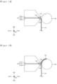
- FIGS. 1a through 1c are drawings illustrating a slot die coater according to an embodiment of the present invention.
- a slot die coater 100 may include a first slot die 100a, a second slot die 100b, and a shim plate 100c.
- the slot die coater 100 may apply a coating solution 220 to the substrate 210. Accordingly, the substrate 210 may be coated with the coating solution 220.
- a coating roll 200 may transport the substrate 210.
- the coating roll 200 may be disposed in front of the slot die coater 100, and the coating roll 200 may be rotated to transfer the substrate 210. As the coating roll 200 drives the substrate 210, the discharged coating solution 220 may be uniformly coated on the substrate 210. To accomplish this, the coating roll 200 may be rotated at a constant speed.
- the slot die coater 100 may dispense the coating solution 220 so as to have a constant spread width and discharge the coating solution 220 at a constant speed.
- At least one of the first slot die 100a and the second slot die 100b may be provided with a storage space for storing the coating solution 220, and the storage space may be supplied with the coating solution 220 via a passageway connected from the outside.
- a shim plate 100c has a first region incised to provide an opening, and may be disposed between a first slot die 100a and a second slot die 100b facing each other. The opening may be located between the first die lip 110a and the second die lip 110b.
- the shim plate 100c is preferably made of a material having a sealing property so as to function as a gasket to prevent the coating solution 220 from leaking into the gap between the first slot die 100a and the second slot die 100b, except for the area where the opening is formed.
- the width of the opening in the shim plate 100c may determine the width over which the coating solution 220 is applied. Multiple openings may be provided, thereby allowing a plurality of coating layers spaced apart from each other to be formed on the substrate 21.
- the result of coating by the slot die coater 100 may be affected by various factors.
- the coating results may be affected by the degree of alignment of the first die lip 110a, which corresponds to an end of the first slot die 100a, and the second die lip 110b, which corresponds to an end of the second slot die 100b.
- the coating result may vary depending on the distance between the first and second die lips 110a, 110b and the shim end 110c, which is the end of the shim plate 100c.
- the slot die coater 100 may further include a motor and a pin.
- the motor may move a pin connected to the motor to move or hold the shim plate 100c.
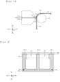
- FIG. 2 is a plan view illustrating an embodiment of a shim plate included in the slot die coater of FIG. 1a .
- the shim plate 100c may include two openings OP1 and OP2.
- the first opening OP1 and the second opening OP2 may each be defined as a space for discharging the coating solution 220.
- the coating solution 220 stored within the slot die coater 100 may be discharged through the first opening OP1 and the second opening OP2, respectively.
- this is exemplary and the shim plate 100c may include one or more openings.
- the slot die coater 100 may establish a tolerance range for the distance between the shim end 110c and the second die lip 110b, and may adjust the position of the shim plate 100c such that the distance between the shim end 110c and the second die lip 110b is within a predetermined tolerance range.
- the position of the shim plate 100c may be adjusted before the first slot die 100a and the second slot die 100b are joined with the shim plate 100c therebetween.
- Whether the distance between the shim end 110c and the second die lip 110b is within the tolerance range can be determined by various criteria. For example, the distance between the shim end 110c and the second die lip 110b may be measured at three locations on the left, center, and right side of the plane, and then compared to determine whether each of the measured distances falls within a respective predetermined tolerance range. However, this is exemplary, and it is also possible to determine whether the distance between the shim end 110c and the second die lip 110b falls within the predetermined tolerance range based on only the two left and right locations.
- the respective tolerances may be determined based on a target value and a finished adjustment value.
- the target value may be defined as an ideal distance between the shim end 110c and the second die lip 110b.
- the ideal distance may refer to the distance between the shim end 110c and the second die lip 110b for the coating solution to be applied normally.
- the left offset distance OFS_L which is the shortest distance between the left portion of the shim end 110c and the second die lip 110b, may have a target value of 500 ⁇ m.
- the target value may be determined by considering various factors. For example, the target value may be determined based on quality measurement results such as coating width, mismatch, sliding, fat edge, etc.
- the finished adjustment value of the left offset distance OFS_L may correspond to a maximum value of the difference between the target value for determining that the shim plate 100c is in the desired position and the measured value of the vision system.
- the finished adjustment value may be 80 ⁇ m, and if the left offset distance OFS_L measured by the vision system is between 420 and 580 ⁇ m, the shim plate 100c may be determined to be in the desired position.
- the tolerance range for the left offset distance OFS_L may be between 420 and 580 ⁇ m.
- the target value can be in a various range of values, and can have a target upper limit and a target lower limit.
- the target value may be 500 ⁇ m
- the target upper limit may be 900 ⁇ m
- the target lower limit may be 100 ⁇ m.
- target value and finished adjustment value described above are exemplary, and the target value and finished adjustment value can be set to various values.
- the target upper limit and target lower limit can be set to different values.
- the shim plate 100c may warp, causing the slot die coater 100 to malfunction and degrade in performance. Therefore, it is desirable that the difference between the maximum value and the minimum value of the left offset distance OFS_L, the right offset distance OFS_R, and the middle offset distance OFS_M is maintained below a preset value, and the preset value may be defined as a preset limit value.
- the preset limit value may be 120 ⁇ m.
- the position of the shim plate 100c can be adjusted again. Since the preset limit value corresponds to the limit value that can be used without causing deformation of the shim plate 100c, it can be determined differently depending on the size or material of the shim plate 100c.
- the first and second pins 300a, 300b may be moved in a first direction DR1 and a second direction DR2 opposite the first direction DR1.
- Each of the first pin 300a and the second pin 300b may penetrate the shim plate 100c and connect with the second slot die 100b.
- the second slot die 100b may be provided with passageways for the first pin 300a and second pin 300b to move.
- one pin may be used to move the shim plate 100c, and three or more pins may be used.
- the description will be based on an embodiment in which two pins 300a, 300b are used to move the shim plate 100c.
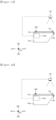
- FIGS. 3a through 3c are drawings illustrating an embodiment of adjusting the position of the shim plate included in the slot die coater of FIG. 1a .
- the vision system 400 may measure the distance between the shim end 110c and the second die lip 110b.
- the vision system 400 may be a camera.
- the distance measured by the vision system 400 may be managed via a control unit (not shown). If the measured distance is outside a predetermined tolerance range, the second motor 500b may move the second pin 300b.
- the second motor 500b may move the second pin 300b in one of the first to sixth directions DR1-6.
- the second motor 500b may comprise a plurality of sub-motors, each of which may move the second pin 300b in a different direction.
- the second motor 500b may include first to third submotors, wherein the first submotor may move the second pin 300b in the first direction DR1 and the second direction DR2, the second submotor may move the second pin 300b in the third direction DR3 and the fourth direction DR4, and the third submotor may move the second pin 300b in the fifth direction DR5 and the sixth direction DR6.
- the second motor 500b may move the second pin 300b in increments of 100 ⁇ m. More preferably, the second motor 500b may move the second pin 300b in increments of 100 ⁇ m or less. For example, the second motor 500b may move the second pin 300b in increments of 50 ⁇ m or 10 ⁇ m. However, this is exemplary, and the second motor 200b may move the second pin 300b in increments of 100 ⁇ m or more. Accordingly, the shim plate 100c may also be moved in increments of 100 ⁇ m or more or less.
- the shim plate 100c can be moved in the first direction DR1 by the second motor 500b and the second pin 300b, thereby allowing the distance between the shim end 110c and the second die lip 110b to fall within a preset tolerance range.
- the position of the shim plate 100c is adjusted by the second motor 500b and the second pin 300b, it can be checked again whether the distance between the shim end 110c and the second die lip 110b falls within the preset tolerance range. If, even after the position of the shim plate 100c is adjusted by the second motor 500b and the second 300b, the distance between the shim end 110c and the second die lip 110b is outside the preset tolerance range, an alarm is sounded and the system is inspected, or a human operator can manually adjust the distance between the shim end 110c and the second die lip 110b to be within the preset tolerance.
- the alarm may be adjusted to sound after adjusting the position of the shim plate 100c at least N times, where N is a natural number greater than or equal to 2.
- the alarm may be set to sound if the distance between the shim end 110c and the second die lip 110b is outside a predetermined tolerance range after adjusting the position of the shim plate 100c five times.
- the second motor 500b can move the second pin 300b in the fourth direction DR4 to secure the shim plate 100c.
- the first slot die 100a, the shim plate 100c, and the second slot die 100b can be combined to stack in sequence, as shown in the slot die coater 100 of FIG. 1a .
- FIGS. 4a and 4b are drawings illustrating an embodiment of adjusting the position of a shim plate included in the slot die coater of FIG. 1a .
- the second motor 500b does not move the second pin 300b in the first direction DR1 or the second direction DR2, but may only move in the fourth direction DR4 to secure the shim plate 100c.
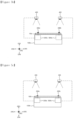
- FIGS. 5a through 5c are drawings illustrating an embodiment of adjusting the position of the shim plate included in the slot die coater of FIG. 1a .
- FIGS. 5a through 5c are drawings illustrating an embodiment in which a motor moves a pin in a fifth direction (DR5) and a sixth direction (DR6).
- one or more vision systems 400 may be provided. Although only one vision system 400 is shown for the sake of illustration, there may be one or more one vision systems 400 in the present specification. If the distance between the end of the shim plate 100c in the fifth direction DR5 and/or in the sixth direction DR6 and the end of the second slot die 100b in the fifth direction DR5 and/or in the sixth direction DR6 measured by the vision system 400 is outside the predetermined tolerance range, the first motor 500a and the second motor 500b can be moved to adjust the position of the shim plate 100c.
- the first motor 500a and the second motor 500b may move the first pin 300a and the second pin 300b in the fourth direction DR4 to fix the position of the shim plate 100c.
- the slot die coater 100 can adjust the position of the shim plate 100c in the first direction DR1, second direction DR2, fifth direction DR5, and sixth direction DR6 to apply the coating solution 220 to have a targeted spread width at a targeted location on the substrate 210.
Landscapes
- Coating Apparatus (AREA)
Abstract
Description
- The present application claims the benefit of and priority to
Korean Patent Application No. 10-2022-0102619, filed August 17, 2022 - The present invention relates to a slot die coater capable of adjusting a position of a shim plate and a method for adjusting a position of a shim plate of a slot die coater, and more particularly, to a slot die coater capable of automatically adjusting the position of the shim plate and a method for automatically adjusting the position of the shim plate based on information measured by a vision system.
- In recent years, as energy prices have risen due to the depletion of fossil fuels and environmental pollution has increased, there has been a growing need for alternative, environmentally friendly energy sources. As a result, various power generation technologies such as nuclear, wind, tidal, and solar power are being researched, and there is a growing interest in power storage to use the generated energy more efficiently.
- In particular, as technology development and demand for mobile devices increase, the demand for batteries as an energy source is rapidly increasing, and research is being conducted on secondary batteries that can meet various needs.
- A secondary battery may include a positive electrode, a negative electrode, and a separator. The positive electrode and negative electrode may be coated with a positive electrode active material and a negative electrode active material, respectively, on the positive electrode collector and the negative electrode collector. In this case, a slot die coater may be used to coat the positive electrode active material and the negative electrode active material.
- The slot die coater is capable of coating the positive electrode active material and the negative electrode active material while maintaining a constant coating width. In order to maintain a constant coating width, the shim plate of the slot die coater must be precisely adjusted within the slot die coater.
- However, the conventional method of adjusting the position of the shim plate by manually adjusting the shim bracket has the limitation that it is difficult to adjust the position of the shim plate precisely, and the disadvantage that time and labor costs are incurred because direct manpower is required to adjust the position of the shim plate.
- Therefore, to overcome these limitations and disadvantages, research is being conducted on techniques to automatically adjust the position of the shim plate.
- It is an objective of the present invention to provide a slot die coater that automatically adjusts the position of a shim plate.
- Another objective of the present invention is to provide a method for automatically adjusting the position of a shim plate.
- However, the objectives addressed by the present invention are not limited to those described above, and other objects not mentioned will be apparent to those skilled in the art from the following description of the invention.
- To accomplish the above objectives of the present invention, a slot die coater according to an embodiment of the present invention may include: a slot die; at least one motor disposed inside the slot die; a shim plate disposed on the slot die; and at least one pin penetrating the shim plate and is connected to the motor, and is moveable by the motor.
- In an embodiment, the pin may be movable in a first direction, which is a direction in which a coating solution is applied, and in a second direction opposite to the first direction.
- In an embodiment, the pin may be movable in a third direction, which is a direction in which the pin penetrates the shim plate, and in a fourth direction opposite the third direction.
- In an embodiment, the pin may be movable in a fifth direction, which is perpendicular to the first direction and the third direction, and in a sixth direction opposite the fifth direction.
- In an embodiment, the motor may adjust the position of the shim plate by moving the pin when a distance between an end of the shim plate and an end of the slot die measured by a vision system is outside a predetermined tolerance range.
- In an embodiment, the motor may be provided in plural and the pin may be provided in plural.
- In order to achieve the above-mentioned objectives of the present invention, a method for adjusting a position of a shim plate according to an embodiment of the present invention may include the steps of: measuring a distance between an end of a slot die and an end of the shim plate disposed on the slot die; determining whether the distance is within a predetermined tolerance range; and adjusting a position of the shim plate in accordance with a result of the determination.
- In an embodiment, the step of adjusting the position of the shim plate may be performed by the pin that penetrates the shim plate and is connected to motor disposed within the slot die.
- In an embodiment, the method may further include: after the step of adjusting the position of the shim plate, a step of securing the shim plate.
- In an embodiment, the step of securing the shim plate may be performed by the pin that penetrates the shim plate and is connected to the motor disposed within the slot die.
- In an embodiment, the method may further include: after the step of adjusting the position of the shim plate, a step of re-measuring a distance between the end of the shim plate and the end of the slot die.
- In an embodiment, the method may further include: after the step of remeasuring, a step of generating an alarm if the distance between the end of the shim plate and the end of the slot die is outside the predetermined tolerance range.
- According to the present invention, a position of a shim plate disposed on a slot die may be automatically adjusted by the pin that penetrates the shim plate and is connected with the slot die. The pin is connected to the motor disposed within the slot die, and the motor may adjust the distance between the shim plate and the slot die by adjusting the position of the pin based on information measured by a vision system. In this way, the present invention can uniformly coat a coating solution on a substrate. In addition, since the position of the shim plate is automatically adjusted through the vision system and the motor, there is no need for additional manpower, which saves cost and time, and the position of the shim plate can be precisely adjusted through the motor and the pin.
-
-
FIGS. 1a through 1c are drawings illustrating a slot die coater according to an embodiment of the present invention. -
FIG. 2 is a plan view illustrating an embodiment of a shim plate included in the slot die coater ofFIG. 1a . -
FIGS. 3a through 3c are drawings illustrating an embodiment of adjusting the position of a shim plate included in the slot die coater ofFIG. 1a . -
FIGS. 4a and4b are drawings illustrating an embodiment of adjusting the position of a shim plate included in the slot die coater ofFIG. 1a . -
FIGS. 5a through 5c are drawings illustrating an embodiment of adjusting the position of a shim plate included in the slot die coater ofFIG. 1a . - Hereinafter, preferred embodiments of the present invention will be described in detail with reference to the accompanying drawings. It should be noted that the terms and words used in this specification and claims are not to be construed in their ordinary or dictionary sense, but rather in a sense and concept consistent with the technical idea of the present invention, based on the principle that the inventor may properly define the concept of a term to best describe his invention. Accordingly, it is to be understood that the embodiments described in the specification and the configurations illustrated in the drawings are only some of the most preferred embodiments of the present invention, and are not exhaustive of the technical ideas of the present invention, and that there may be various equivalents and modifications that may replace them at the time of filing.
- The slot die coater of the present invention is an apparatus having a slot and applying a coating solution on a substrate through the slot. The slot die coater may be provided with a first slot die and a second slot die. The "substrate" described herein is a collector, and the "coating solution" is an "electrode active material slurry". However, the scope of the present invention is not limited thereto. For example, the substrate may be a porous support comprising a separator, and the coating solution may be an organic material. In other words, the substrate and coating solution may be any material as long as a thin film coating is desired.
- In this specification, the first direction DR1 is defined as a direction in which the coating solution is discharged, the second direction DR2 is defined as a direction opposite to the first direction DR1, the third direction DR3 and the fourth direction DR4 are defined as directions perpendicular to the first direction DR1 and the second direction DR2, respectively, and the fifth direction DR5 and the sixth direction DR6 are defined as directions perpendicular to the first direction DR1 and the third direction DR3, respectively.
-
FIGS. 1a through 1c are drawings illustrating a slot die coater according to an embodiment of the present invention. - Referring to
FIGS. 1a through 1c , aslot die coater 100 according to an embodiment of the present invention may include a first slot die 100a, a second slot die 100b, and ashim plate 100c. The slot diecoater 100 may apply acoating solution 220 to thesubstrate 210. Accordingly, thesubstrate 210 may be coated with thecoating solution 220. Acoating roll 200 may transport thesubstrate 210. Thecoating roll 200 may be disposed in front of theslot die coater 100, and thecoating roll 200 may be rotated to transfer thesubstrate 210. As thecoating roll 200 drives thesubstrate 210, the dischargedcoating solution 220 may be uniformly coated on thesubstrate 210. To accomplish this, thecoating roll 200 may be rotated at a constant speed. In addition, theslot die coater 100 may dispense thecoating solution 220 so as to have a constant spread width and discharge thecoating solution 220 at a constant speed. - Although not shown, at least one of the
first slot die 100a and thesecond slot die 100b may be provided with a storage space for storing thecoating solution 220, and the storage space may be supplied with thecoating solution 220 via a passageway connected from the outside. - A
shim plate 100c has a first region incised to provide an opening, and may be disposed between afirst slot die 100a and a second slot die 100b facing each other. The opening may be located between thefirst die lip 110a and thesecond die lip 110b. Theshim plate 100c is preferably made of a material having a sealing property so as to function as a gasket to prevent thecoating solution 220 from leaking into the gap between thefirst slot die 100a and thesecond slot die 100b, except for the area where the opening is formed. - The width of the opening in the
shim plate 100c may determine the width over which thecoating solution 220 is applied. Multiple openings may be provided, thereby allowing a plurality of coating layers spaced apart from each other to be formed on the substrate 21. - The result of coating by the
slot die coater 100 may be affected by various factors. For example, the coating results may be affected by the degree of alignment of thefirst die lip 110a, which corresponds to an end of thefirst slot die 100a, and thesecond die lip 110b, which corresponds to an end of thesecond slot die 100b. Alternatively, the coating result may vary depending on the distance between the first and second dielips shim end 110c, which is the end of theshim plate 100c. - If the distance between the first and second die
lips shim end 110c becomes too large, the spreading width of thecoating solution 220 may become large when thecoating solution 220 is applied, and thecoating solution 220 may not be uniformly applied on thesubstrate 210. Therefore, to adjust the distance between the first and second dielips shim end 110c, theslot die coater 100 may further include a motor and a pin. The motor may move a pin connected to the motor to move or hold theshim plate 100c. These motor and pin will be described with reference to the following drawings. -
FIG. 2 is a plan view illustrating an embodiment of a shim plate included in the slot die coater ofFIG. 1a . - Referring to
FIGS. 1a and2 , theshim plate 100c may include two openings OP1 and OP2. The first opening OP1 and the second opening OP2 may each be defined as a space for discharging thecoating solution 220. In other words, thecoating solution 220 stored within theslot die coater 100 may be discharged through the first opening OP1 and the second opening OP2, respectively. However, this is exemplary and theshim plate 100c may include one or more openings. - As described above, the distance between the
shim end 110c and thesecond die lip 110b may vary the coating result. Therefore, theslot die coater 100 according to an embodiment of the present invention may establish a tolerance range for the distance between theshim end 110c and thesecond die lip 110b, and may adjust the position of theshim plate 100c such that the distance between theshim end 110c and thesecond die lip 110b is within a predetermined tolerance range. The position of theshim plate 100c may be adjusted before thefirst slot die 100a and thesecond slot die 100b are joined with theshim plate 100c therebetween. - Whether the distance between the
shim end 110c and thesecond die lip 110b is within the tolerance range can be determined by various criteria. For example, the distance between theshim end 110c and thesecond die lip 110b may be measured at three locations on the left, center, and right side of the plane, and then compared to determine whether each of the measured distances falls within a respective predetermined tolerance range. However, this is exemplary, and it is also possible to determine whether the distance between theshim end 110c and thesecond die lip 110b falls within the predetermined tolerance range based on only the two left and right locations. - The respective tolerances may be determined based on a target value and a finished adjustment value. The target value may be defined as an ideal distance between the
shim end 110c and thesecond die lip 110b. The ideal distance may refer to the distance between theshim end 110c and thesecond die lip 110b for the coating solution to be applied normally. For example, regarding the left side of theshim plate 100c, the left offset distance OFS_L, which is the shortest distance between the left portion of theshim end 110c and thesecond die lip 110b, may have a target value of 500 µm. The target value may be determined by considering various factors. For example, the target value may be determined based on quality measurement results such as coating width, mismatch, sliding, fat edge, etc. - The finished adjustment value of the left offset distance OFS_L may correspond to a maximum value of the difference between the target value for determining that the
shim plate 100c is in the desired position and the measured value of the vision system. For example, the finished adjustment value may be 80 µm, and if the left offset distance OFS_L measured by the vision system is between 420 and 580 µm, theshim plate 100c may be determined to be in the desired position. In other words, the tolerance range for the left offset distance OFS_L may be between 420 and 580 µm. - The target value can be in a various range of values, and can have a target upper limit and a target lower limit. For example, the target value may be 500 µm, the target upper limit may be 900 µm, and the target lower limit may be 100 µm.
- The target value and finished adjustment value described above are exemplary, and the target value and finished adjustment value can be set to various values. In addition, the target upper limit and target lower limit can be set to different values.
- Also, while the description of the above values is based on the left offset distance OFS_L, the description of the above values can be equally applied to the right offset distance OFS_R and the middle offset distance OFS_M.
- However, if the difference between the maximum and minimum values of the left offset distance OFS_L, the right offset distance OFS_R, and the middle offset distance OFS_M becomes larger than a preset value, the
shim plate 100c may warp, causing theslot die coater 100 to malfunction and degrade in performance. Therefore, it is desirable that the difference between the maximum value and the minimum value of the left offset distance OFS_L, the right offset distance OFS_R, and the middle offset distance OFS_M is maintained below a preset value, and the preset value may be defined as a preset limit value. The preset limit value may be 120 µm. For example, if the difference between the left offset distance OFS_L and the right offset distance OFS_R exceeds 120 µm, the position of theshim plate 100c can be adjusted again. Since the preset limit value corresponds to the limit value that can be used without causing deformation of theshim plate 100c, it can be determined differently depending on the size or material of theshim plate 100c. - In order for the distance between the
shim end 110c and thesecond die lip 110b to be within a predetermined tolerance range, the first andsecond pins first pin 300a and thesecond pin 300b may penetrate theshim plate 100c and connect with thesecond slot die 100b. Thesecond slot die 100b may be provided with passageways for thefirst pin 300a andsecond pin 300b to move. As shown inFIG. 2 , one pin may be used to move theshim plate 100c, and three or more pins may be used. However, for ease of explanation, the description will be based on an embodiment in which twopins shim plate 100c. -
FIGS. 3a through 3c are drawings illustrating an embodiment of adjusting the position of the shim plate included in the slot die coater ofFIG. 1a . - Referring to
FIG. 3a , thevision system 400 may measure the distance between theshim end 110c and thesecond die lip 110b. Thevision system 400 may be a camera. The distance measured by thevision system 400 may be managed via a control unit (not shown). If the measured distance is outside a predetermined tolerance range, thesecond motor 500b may move thesecond pin 300b. Here, thesecond motor 500b may move thesecond pin 300b in one of the first to sixth directions DR1-6. Alternatively, thesecond motor 500b may comprise a plurality of sub-motors, each of which may move thesecond pin 300b in a different direction. For example, thesecond motor 500b may include first to third submotors, wherein the first submotor may move thesecond pin 300b in the first direction DR1 and the second direction DR2, the second submotor may move thesecond pin 300b in the third direction DR3 and the fourth direction DR4, and the third submotor may move thesecond pin 300b in the fifth direction DR5 and the sixth direction DR6. - In this case, the
second motor 500b may move thesecond pin 300b in increments of 100 µm. More preferably, thesecond motor 500b may move thesecond pin 300b in increments of 100 µm or less. For example, thesecond motor 500b may move thesecond pin 300b in increments of 50 µm or 10 µm. However, this is exemplary, and the second motor 200b may move thesecond pin 300b in increments of 100 µm or more. Accordingly, theshim plate 100c may also be moved in increments of 100 µm or more or less. - Referring to
FIGS. 3a and 3b , theshim plate 100c can be moved in the first direction DR1 by thesecond motor 500b and thesecond pin 300b, thereby allowing the distance between theshim end 110c and thesecond die lip 110b to fall within a preset tolerance range. - After the position of the
shim plate 100c is adjusted by thesecond motor 500b and thesecond pin 300b, it can be checked again whether the distance between theshim end 110c and thesecond die lip 110b falls within the preset tolerance range. If, even after the position of theshim plate 100c is adjusted by thesecond motor 500b and the second 300b, the distance between theshim end 110c and thesecond die lip 110b is outside the preset tolerance range, an alarm is sounded and the system is inspected, or a human operator can manually adjust the distance between theshim end 110c and thesecond die lip 110b to be within the preset tolerance. However, the alarm may be adjusted to sound after adjusting the position of theshim plate 100c at least N times, where N is a natural number greater than or equal to 2. For example, the alarm may be set to sound if the distance between theshim end 110c and thesecond die lip 110b is outside a predetermined tolerance range after adjusting the position of theshim plate 100c five times. - Referring to
FIGS. 3b and3c , when it is determined by thevision system 400 that the distance between theshim end 110c and thesecond die lip 110b is within the predetermined tolerance range, thesecond motor 500b can move thesecond pin 300b in the fourth direction DR4 to secure theshim plate 100c. - Once the
shim plate 100c is secured, thefirst slot die 100a, theshim plate 100c, and the second slot die 100b can be combined to stack in sequence, as shown in theslot die coater 100 ofFIG. 1a . -
FIGS. 4a and4b are drawings illustrating an embodiment of adjusting the position of a shim plate included in the slot die coater ofFIG. 1a . - Referring to
FIGS. 4a and4b , if it is determined by thevision system 400 that the distance between theshim end 110c and thesecond die lip 110b is within the predetermined tolerance range, thesecond motor 500b does not move thesecond pin 300b in the first direction DR1 or the second direction DR2, but may only move in the fourth direction DR4 to secure theshim plate 100c. -
FIGS. 5a through 5c are drawings illustrating an embodiment of adjusting the position of the shim plate included in the slot die coater ofFIG. 1a .FIGS. 5a through 5c are drawings illustrating an embodiment in which a motor moves a pin in a fifth direction (DR5) and a sixth direction (DR6). - Referring to
FIGS. 5a and5b , one ormore vision systems 400 may be provided. Although only onevision system 400 is shown for the sake of illustration, there may be one or more onevision systems 400 in the present specification. If the distance between the end of theshim plate 100c in the fifth direction DR5 and/or in the sixth direction DR6 and the end of the second slot die 100b in the fifth direction DR5 and/or in the sixth direction DR6 measured by thevision system 400 is outside the predetermined tolerance range, thefirst motor 500a and thesecond motor 500b can be moved to adjust the position of theshim plate 100c. - Subsequently, if the
vision system 400 confirms that theshim plate 100c is within a targeted tolerance, thefirst motor 500a and thesecond motor 500b may move thefirst pin 300a and thesecond pin 300b in the fourth direction DR4 to fix the position of theshim plate 100c. - As such, the
slot die coater 100 according to an embodiment of the present invention can adjust the position of theshim plate 100c in the first direction DR1, second direction DR2, fifth direction DR5, and sixth direction DR6 to apply thecoating solution 220 to have a targeted spread width at a targeted location on thesubstrate 210. - While the present invention has been described in detail above with respect to preferred embodiments of the present invention, the scope of the present invention is not limited thereto, and various modifications and improvements by those skilled in the art using the basic concepts of the present invention as defined in the following claims are also within the scope of the present invention.
-
- 100: slot die coater
- 100a: first slot die
- 100b: second slot die
- 100c: shim plate
- 110a: first die lip
- 110b: second die lip
- 110c: shim end
- 200: coating roll
- 210: substrate
- 220: coating solution
- 300a, 300b: first and second pins
- 400: vision system
- 500a, 500b: first and second motors
Claims (12)
- A slot die coater for automatically adjusting a position of a shim plate, comprising:a slot die;at least one motor disposed inside the slot die;the shim plate disposed on the slot die; andat least one pin which is connected to the motor through the shim plate, wherein the pin is moveable by the motor.
- The slot die coater of claim 1, wherein the pin is movable in a first direction, which is a direction in which a coating solution is applied, and in a second direction opposite to the first direction.
- The slot die coater of claim 2, wherein the pin is movable in a third direction, which is a direction in which the pin penetrates the shim plate, and in a fourth direction opposite the third direction.
- The slot die coater of claim 3, wherein the pin is movable in a fifth direction, which is perpendicular to the first direction and the third direction, and in a sixth direction opposite the fifth direction.
- The slot die coater of claim 1, wherein the motor adjusts the position of the shim plate by moving the pin when a distance between an end of the shim plate and an end of the slot die measured by a vision system is outside a predetermined tolerance range.
- The slot die coater of claim 5, wherein the motor is provided in plural and the pin is provided in plural.
- A method for adjusting a position of a shim plate of a slot die coater, comprising the steps of:measuring a distance between an end of a slot die and an end of the shim plate disposed on the slot die;determining whether the distance is within a predetermined tolerance range; andadjusting a position of the shim plate in accordance with a result of the determination.
- The method of claim 7, wherein the step of adjusting the position of the shim plate is performed by the pin that penetrates the shim plate and is connected to motor disposed within the slot die.
- The method of claim 7, further comprising, after the step of adjusting the position of the shim plate, a step of securing the shim plate.
- The method of claim 9, wherein the step of securing the shim plate is performed by the pin that penetrates the shim plate and is connected to motor disposed within the slot die.
- The method of claim 7, further comprising, after the step of adjusting the position of the shim plate, a step of re-measuring a distance between the end of the shim plate and the end of the slot die.
- The method of claim 11, further comprising, after the step of remeasuring, a step of generating an alarm if the distance between the end of the shim plate and the end of the slot die is outside the predetermined tolerance range.
Applications Claiming Priority (2)
| Application Number | Priority Date | Filing Date | Title |
|---|---|---|---|
| KR1020220102619A KR20240024528A (en) | 2022-08-17 | 2022-08-17 | Slot die coater capable of automatically adjusting position of the shim plate and method of adjusting position of shim plate of slot die coater |
| PCT/KR2023/012144 WO2024039190A1 (en) | 2022-08-17 | 2023-08-17 | Slot die coater capable of automatically controlling position of shim plate and method for controlling position of shim plate of slot die coater |
Publications (2)
| Publication Number | Publication Date |
|---|---|
| EP4549031A1 true EP4549031A1 (en) | 2025-05-07 |
| EP4549031A4 EP4549031A4 (en) | 2025-11-05 |
Family
ID=89941951
Family Applications (1)
| Application Number | Title | Priority Date | Filing Date |
|---|---|---|---|
| EP23855156.8A Pending EP4549031A4 (en) | 2022-08-17 | 2023-08-17 | Slot nozzle coater with function for automatic control of the position of a shimp plate and method for controlling the position of the shimp plate of a slot nozzle coater |
Country Status (5)
| Country | Link |
|---|---|
| EP (1) | EP4549031A4 (en) |
| JP (1) | JP2025520561A (en) |
| KR (1) | KR20240024528A (en) |
| CN (1) | CN119365272A (en) |
| WO (1) | WO2024039190A1 (en) |
Families Citing this family (1)
| Publication number | Priority date | Publication date | Assignee | Title |
|---|---|---|---|---|
| WO2026054522A1 (en) * | 2024-09-06 | 2026-03-12 | 주식회사 엘지에너지솔루션 | Coating device |
Family Cites Families (10)
| Publication number | Priority date | Publication date | Assignee | Title |
|---|---|---|---|---|
| JPH07204561A (en) * | 1994-01-19 | 1995-08-08 | Mitsubishi Heavy Ind Ltd | Slit nozzle coating device |
| JP2939802B2 (en) * | 1998-01-12 | 1999-08-25 | 井上金属工業株式会社 | Coating equipment |
| KR101897827B1 (en) * | 2012-02-28 | 2018-09-12 | 삼성에스디아이 주식회사 | Slot die for controlling slurry coating width |
| CN205887355U (en) * | 2016-07-27 | 2017-01-18 | 江苏楚汉新能源科技有限公司 | Coating die gasket position simple adjustment device |
| KR101922054B1 (en) * | 2017-04-26 | 2018-11-26 | 성안기계 주식회사 | Slot die with variable manifold and method for controlling the same |
| JP6927845B2 (en) * | 2017-10-20 | 2021-09-01 | 株式会社ヒラノテクシード | Coating equipment |
| JP6936139B2 (en) * | 2017-12-21 | 2021-09-15 | 株式会社ヒラノテクシード | Coating equipment |
| CN210279700U (en) * | 2019-07-17 | 2020-04-10 | 宁波维科电池有限公司 | Coating die head for single-group or multi-group lithium battery pole piece |
| US12390764B2 (en) | 2019-11-22 | 2025-08-19 | Basf Mobile Emissions Catalysts Llc | Emmission control catalyst article with enriched PGM zone |
| KR102837050B1 (en) * | 2020-10-27 | 2025-07-23 | 주식회사 엘지에너지솔루션 | Die Coater Inspecting Apparatus |
-
2022
- 2022-08-17 KR KR1020220102619A patent/KR20240024528A/en active Pending
-
2023
- 2023-08-17 WO PCT/KR2023/012144 patent/WO2024039190A1/en not_active Ceased
- 2023-08-17 CN CN202380046222.4A patent/CN119365272A/en active Pending
- 2023-08-17 JP JP2024574010A patent/JP2025520561A/en active Pending
- 2023-08-17 EP EP23855156.8A patent/EP4549031A4/en active Pending
Also Published As
| Publication number | Publication date |
|---|---|
| CN119365272A (en) | 2025-01-24 |
| WO2024039190A1 (en) | 2024-02-22 |
| EP4549031A4 (en) | 2025-11-05 |
| KR20240024528A (en) | 2024-02-26 |
| JP2025520561A (en) | 2025-07-03 |
Similar Documents
| Publication | Publication Date | Title |
|---|---|---|
| US11161140B2 (en) | Slot die coater for changing coating form of electrode active material slurry through movement of slots | |
| EP3782737A1 (en) | Slot die coater adjusting device for controlling distance between upper discharge port and lower discharge port of slot die coater, and electrode active material coating system including same | |
| US9067229B2 (en) | Active material coating apparatus and coating method using the same | |
| US20220203572A1 (en) | Apparatus and method for notching electrode sheet | |
| US11764345B2 (en) | Coating apparatus | |
| US20240033772A1 (en) | Slot Die Coating Device Having Air Vent | |
| EP3576164A1 (en) | Loading tray for double-sided film coating, silicon chip loading device and silicon chip conveying system | |
| CN119365272A (en) | Slot die coater capable of automatically adjusting position of shim plate and method for adjusting position of shim plate of slot die coater | |
| KR20220095390A (en) | Secondary battery electrode manufacturing system and method | |
| KR102922371B1 (en) | System for manufacturing lithum secondary battery | |
| KR20210058130A (en) | Electrode automatic supply device for secondary battery manufacturing and electrode automatic supply method using the same | |
| KR102257083B1 (en) | Apparatus for manufacturing secondary battery | |
| US10790776B2 (en) | System and method for controlling the power ratio of a solar concentrator array | |
| KR102925846B1 (en) | Apparatus of manufacturing electrode and method of manufacturing electrode | |
| KR20240101364A (en) | Unwinding device for secondary battery manufacturing and secondary battery manufacturing system including same | |
| KR20240111595A (en) | Electrode manufacturing apparatus and method | |
| KR20220056056A (en) | Die Coater Inspecting Apparatus | |
| KR20230081220A (en) | The apparatus and method for coating electrode active material | |
| CA2360184A1 (en) | Solid polymer electrolyte membrane comprising a moisture-proof layer and fuel cell comprising same | |
| KR20240029438A (en) | Apparatus for manufacturing electrodes and method for manufacturing electrodes | |
| CN223528414U (en) | Photovoltaic carrier film | |
| US20250140889A1 (en) | Sheet connection device and method for secondary battery | |
| KR102956337B1 (en) | Die coater | |
| EP4672347A1 (en) | ELECTRODE MANUFACTURING DEVICE | |
| EP4246604A1 (en) | Electrode slurry-supplying apparatus, coating apparatus, and die coater |
Legal Events
| Date | Code | Title | Description |
|---|---|---|---|
| STAA | Information on the status of an ep patent application or granted ep patent |
Free format text: STATUS: THE INTERNATIONAL PUBLICATION HAS BEEN MADE |
|
| PUAI | Public reference made under article 153(3) epc to a published international application that has entered the european phase |
Free format text: ORIGINAL CODE: 0009012 |
|
| STAA | Information on the status of an ep patent application or granted ep patent |
Free format text: STATUS: REQUEST FOR EXAMINATION WAS MADE |
|
| 17P | Request for examination filed |
Effective date: 20250131 |
|
| AK | Designated contracting states |
Kind code of ref document: A1 Designated state(s): AL AT BE BG CH CY CZ DE DK EE ES FI FR GB GR HR HU IE IS IT LI LT LU LV MC ME MK MT NL NO PL PT RO RS SE SI SK SM TR |
|
| A4 | Supplementary search report drawn up and despatched |
Effective date: 20251008 |
|
| RIC1 | Information provided on ipc code assigned before grant |
Ipc: B05C 5/02 20060101AFI20251001BHEP Ipc: B05C 11/02 20060101ALI20251001BHEP Ipc: B05D 1/26 20060101ALI20251001BHEP |
|
| DAV | Request for validation of the european patent (deleted) | ||
| DAX | Request for extension of the european patent (deleted) |