EP4548946A1 - Cannula port, cradle device and drug solution administration device - Google Patents
Cannula port, cradle device and drug solution administration device Download PDFInfo
- Publication number
- EP4548946A1 EP4548946A1 EP23871389.5A EP23871389A EP4548946A1 EP 4548946 A1 EP4548946 A1 EP 4548946A1 EP 23871389 A EP23871389 A EP 23871389A EP 4548946 A1 EP4548946 A1 EP 4548946A1
- Authority
- EP
- European Patent Office
- Prior art keywords
- cannula
- main body
- flow path
- fixing member
- accommodation space
- Prior art date
- Legal status (The legal status is an assumption and is not a legal conclusion. Google has not performed a legal analysis and makes no representation as to the accuracy of the status listed.)
- Withdrawn
Links
Images







Classifications
-
- A—HUMAN NECESSITIES
- A61—MEDICAL OR VETERINARY SCIENCE; HYGIENE
- A61M—DEVICES FOR INTRODUCING MEDIA INTO, OR ONTO, THE BODY; DEVICES FOR TRANSDUCING BODY MEDIA OR FOR TAKING MEDIA FROM THE BODY; DEVICES FOR PRODUCING OR ENDING SLEEP OR STUPOR
- A61M5/00—Devices for bringing media into the body in a subcutaneous, intra-vascular or intramuscular way; Accessories therefor, e.g. filling or cleaning devices, arm-rests
- A61M5/14—Infusion devices, e.g. infusing by gravity; Blood infusion; Accessories therefor
- A61M5/158—Needles for infusions; Accessories therefor, e.g. for inserting infusion needles, or for holding them on the body
-
- A—HUMAN NECESSITIES
- A61—MEDICAL OR VETERINARY SCIENCE; HYGIENE
- A61M—DEVICES FOR INTRODUCING MEDIA INTO, OR ONTO, THE BODY; DEVICES FOR TRANSDUCING BODY MEDIA OR FOR TAKING MEDIA FROM THE BODY; DEVICES FOR PRODUCING OR ENDING SLEEP OR STUPOR
- A61M5/00—Devices for bringing media into the body in a subcutaneous, intra-vascular or intramuscular way; Accessories therefor, e.g. filling or cleaning devices, arm-rests
- A61M5/14—Infusion devices, e.g. infusing by gravity; Blood infusion; Accessories therefor
- A61M5/142—Pressure infusion, e.g. using pumps
- A61M5/14244—Pressure infusion, e.g. using pumps adapted to be carried by the patient, e.g. portable on the body
- A61M5/14248—Pressure infusion, e.g. using pumps adapted to be carried by the patient, e.g. portable on the body of the skin patch type
-
- A—HUMAN NECESSITIES
- A61—MEDICAL OR VETERINARY SCIENCE; HYGIENE
- A61M—DEVICES FOR INTRODUCING MEDIA INTO, OR ONTO, THE BODY; DEVICES FOR TRANSDUCING BODY MEDIA OR FOR TAKING MEDIA FROM THE BODY; DEVICES FOR PRODUCING OR ENDING SLEEP OR STUPOR
- A61M5/00—Devices for bringing media into the body in a subcutaneous, intra-vascular or intramuscular way; Accessories therefor, e.g. filling or cleaning devices, arm-rests
- A61M5/14—Infusion devices, e.g. infusing by gravity; Blood infusion; Accessories therefor
- A61M5/142—Pressure infusion, e.g. using pumps
- A61M5/14244—Pressure infusion, e.g. using pumps adapted to be carried by the patient, e.g. portable on the body
- A61M2005/14268—Pressure infusion, e.g. using pumps adapted to be carried by the patient, e.g. portable on the body with a reusable and a disposable component
-
- A—HUMAN NECESSITIES
- A61—MEDICAL OR VETERINARY SCIENCE; HYGIENE
- A61M—DEVICES FOR INTRODUCING MEDIA INTO, OR ONTO, THE BODY; DEVICES FOR TRANSDUCING BODY MEDIA OR FOR TAKING MEDIA FROM THE BODY; DEVICES FOR PRODUCING OR ENDING SLEEP OR STUPOR
- A61M5/00—Devices for bringing media into the body in a subcutaneous, intra-vascular or intramuscular way; Accessories therefor, e.g. filling or cleaning devices, arm-rests
- A61M5/14—Infusion devices, e.g. infusing by gravity; Blood infusion; Accessories therefor
- A61M5/158—Needles for infusions; Accessories therefor, e.g. for inserting infusion needles, or for holding them on the body
- A61M2005/1585—Needle inserters
-
- A—HUMAN NECESSITIES
- A61—MEDICAL OR VETERINARY SCIENCE; HYGIENE
- A61M—DEVICES FOR INTRODUCING MEDIA INTO, OR ONTO, THE BODY; DEVICES FOR TRANSDUCING BODY MEDIA OR FOR TAKING MEDIA FROM THE BODY; DEVICES FOR PRODUCING OR ENDING SLEEP OR STUPOR
- A61M5/00—Devices for bringing media into the body in a subcutaneous, intra-vascular or intramuscular way; Accessories therefor, e.g. filling or cleaning devices, arm-rests
- A61M5/14—Infusion devices, e.g. infusing by gravity; Blood infusion; Accessories therefor
- A61M5/158—Needles for infusions; Accessories therefor, e.g. for inserting infusion needles, or for holding them on the body
- A61M2005/1586—Holding accessories for holding infusion needles on the body
-
- A—HUMAN NECESSITIES
- A61—MEDICAL OR VETERINARY SCIENCE; HYGIENE
- A61M—DEVICES FOR INTRODUCING MEDIA INTO, OR ONTO, THE BODY; DEVICES FOR TRANSDUCING BODY MEDIA OR FOR TAKING MEDIA FROM THE BODY; DEVICES FOR PRODUCING OR ENDING SLEEP OR STUPOR
- A61M5/00—Devices for bringing media into the body in a subcutaneous, intra-vascular or intramuscular way; Accessories therefor, e.g. filling or cleaning devices, arm-rests
- A61M5/14—Infusion devices, e.g. infusing by gravity; Blood infusion; Accessories therefor
- A61M5/158—Needles for infusions; Accessories therefor, e.g. for inserting infusion needles, or for holding them on the body
- A61M2005/1587—Needles for infusions; Accessories therefor, e.g. for inserting infusion needles, or for holding them on the body suitable for being connected to an infusion line after insertion into a patient
Definitions
- the present disclosure relates to a cannula port, a cradle device, and a liquid medicine administration device.
- a treatment method of continuously administering a liquid medicine into the body of a patient by subcutaneous injection, intravenous injection, or the like has been performed.
- a treatment method for a diabetic patient a treatment of continuously injecting a trace amount of insulin into the body of the patient is performed.
- an insulin pump is used as a portable liquid medicine administration device that can be fixed and carried on the patient's body or clothes.
- Patent Literature 1 discloses a cannula unit used for this type of insulin pump.
- Patent Literature 1 The cannula unit described in Patent Literature 1 includes a cannula and a housing.
- Patent Literature 1 discloses a configuration in which a cannula is sandwiched between a bore of a first portion of a housing and a bush of a second portion of the housing.
- Patent Literature 1 WO 2018/033614
- the cannula As in the cannula unit described in Patent Literature 1, the cannula is sandwiched and fixed by the first portion and the second portion of the housing, whereby the cannula is firmly fixed to the housing.
- the second portion including the bush as the fixing member described in Patent Literature 1 is adopted, the dead volume in which the liquid medicine is retained in the housing tends to be large.
- a space in the bush of the second portion becomes the dead volume in which the liquid medicine remains after completion of the liquid medicine administration to the living body. Therefore, it is not preferable from the viewpoint of saving the liquid medicine.
- the space in the bush of the second portion of Patent Literature 1 is used not only as a flow path of the liquid medicine but also as a passage hole of an inner needle.
- the inner needle is inserted into the living body together with the cannula in a state of being inserted into the cannula, and is removed from the cannula after the cannula is indwelled in the living body.
- the diameter of the space in the bush of the second portion of Patent Literature 1 is reduced for the purpose of reducing the dead volume described above, it is difficult to insert the inner needle into the space in the bush of the second portion.
- An object of the present disclosure is to provide a cannula port, a cradle device, and a liquid medicine administration device capable of reducing a dead volume in which a liquid medicine remains and suppressing deterioration of passability of an inner needle.
- a cannula port according to a first aspect of the present disclosure is a cannula port including:
- a cannula port according to an embodiment of the present disclosure is (2) the cannula port according to (1), further including a septum disposed adjacent to the fixing member so as to cover a removal direction of the fixing member in the accommodation space of the cannula housing when a direction from the distal end toward the proximal end in the axial direction of the tube main body portion is the removal direction.
- a cannula port according to an embodiment of the present disclosure is (3) the cannula port according to (2), in which:
- a cannula port according to an embodiment of the present disclosure is (4)
- a cannula port according to an embodiment of the present disclosure is (5) the cannula port according to any one of (1) to (4), in which the cannula housing includes, on an inner surface that defines the accommodation space, a locking portion that locks the fixing member.
- a cannula port according to an embodiment of the present disclosure is (6)
- a cradle device is (7)
- a liquid medicine administration device is (8)
- a cannula port capable of reducing a dead volume in which a liquid medicine remains and suppressing deterioration of passability of an inner needle.
- Fig. 1 is a perspective view illustrating the liquid medicine administration device 1.
- Fig. 2 is a perspective view illustrating a state before a device main body 2 and a cradle device 3 of the liquid medicine administration device 1 are attached to each other.
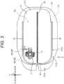
- Fig. 3 is a plan view illustrating the cradle device 3.
- Fig. 4 is an explanatory view illustrating a state where the device main body 2 is being attached to the cradle device 3.
- the liquid medicine administration device 1 is a portable insulin pump for continuously administering a liquid medicine into a living body such as a patient like a patch-type or tube-type insulin pump and other portable liquid medicine administration devices.
- the liquid medicine administration device according to the present disclosure is not limited to the insulin pump illustrated in Fig. 1 , but in the present embodiment, an insulin pump as an example of the liquid medicine administration device according to the present disclosure will be described by way of example.
- the liquid medicine administration device 1 includes the device main body 2 and the cradle device 3 configured to be attachable to and detachable from the device main body 2.
- the cradle device 3 includes a cannula port 6 described later.
- the cannula port 6 includes a cannula 81 that can be inserted into the living body from the surface of the living body.
- the device main body 2 includes a hollow housing 11. Additionally, as illustrated in Fig. 4 , the device main body 2 includes a connecting needle tube 12. Furthermore, as illustrated in Fig. 4 , the device main body 2 includes a liquid delivery pipe 13, a liquid medicine container 14, and a drive unit 15 in the housing 11.
- the liquid medicine container 14 stores a liquid medicine to be administered into a living body. One end portion of the liquid delivery pipe 13 is connected to the liquid medicine container 14. The other end portion of the liquid delivery pipe 13 is connected to the connecting needle tube 12.
- the drive unit 15 can send the liquid medicine stored in the liquid medicine container 14 into the liquid delivery pipe 13.
- the liquid medicine sent into the liquid delivery pipe 13 from the liquid medicine container 14 is discharged from the device main body 2 through the connecting needle tube 12.
- the connecting needle tube 12 is punctured into a connecting portion 82a of the cannula port 6 described later in a state where the device main body 2 is attached to the cradle device 3.
- the liquid delivery pipe 13 and the connecting portion 82a are connected via the connecting needle tube 12.
- an attaching and detaching direction A a direction in which the device main body 2 is attached to and detached from the cradle device 3 will be referred to as an attaching and detaching direction A.
- an attachment direction A1 a direction in which the device main body 2 is moved with respect to the cradle device 3 at the time of attachment.
- a detachment direction A2 a direction in which the device main body 2 is moved with respect to the cradle device 3 at the time of detachment.
- a direction orthogonal to the attaching and detaching direction A and also orthogonal to a direction in which the device main body 2 and the cradle device 3 overlap with each other is referred to as a device width direction B.
- a direction in which the device main body 2 and the cradle device 3 overlap each other, that is, a direction orthogonal to the attaching and detaching direction A and the device width direction B is referred to as a device height direction C.
- the housing 11 may be formed in a flat and substantially rectangular parallelepiped shape having curved corners.
- the housing 11 of the present embodiment includes a top plate portion 21, a bottom plate portion 22, a front plate portion 23, a rear plate portion 24, a first side plate portion 25, and a second side plate portion 26.
- the top plate portion 21 and the bottom plate portion 22 face each other in the device height direction C.
- the top plate portion 21 is formed in a substantially rectangular shape with curved corners. Additionally, the central portion of the top plate portion 21 bulges toward the side opposite to the bottom plate portion 22 in the device height direction C.
- the front plate portion 23 is substantially vertically continuous to one end portion of the top plate portion 21 in the attaching and detaching direction A
- the rear plate portion 24 is substantially vertically continuous to the other end portion of the top plate portion 21 in the attaching and detaching direction A.
- the front plate portion 23 and the rear plate portion 24 face each other in the attaching and detaching direction A.
- the first side plate portion 25 is substantially vertically continuous to one end portion of the top plate portion 21 in the device width direction B
- the second side plate portion 26 is substantially vertically continuous to the other end portion of the top plate portion 21 in the device width direction B.
- a sliding groove 32 that accommodates a sliding rail 53, which will be described later, of the cradle device 3, and slides with the sliding rail 53 is formed in the bottom plate portion 22.
- the bottom plate portion 22 may be provided with, for example, an attachment detection switch capable of detecting a state in which the device main body 2 is attached to the cradle device 3.
- the housing 11 defines a port accommodating portion 27 capable of accommodating the cannula port 6 described later in a state where the device main body 2 is attached to the cradle device 3.
- the port accommodating portion 27 is formed in a corner where the bottom plate portion 22, the first side plate portion 25, and the front plate portion 23 in the housing 11 are continuous.
- the port accommodating portion 27 is a recess recessed by a predetermined length from the bottom plate portion 22 toward the top plate portion 21 along the device height direction C.
- a tubular connection port 28 is formed in a side wall 27a defining the detachment direction A2 of the port accommodating portion 27.
- the connection port 28 protrudes from the side wall 27a in the attachment direction A1.
- the connecting needle tube 12 is disposed in the cylindrical hole of the connection port 28.
- the connecting needle tube 12 protrudes from the side wall 27a in the attachment direction A1.
- the first side plate portion 25 and the second side plate portion 26 of the housing 11 may be provided with a locking portion that engages with a receiving portion of the cradle device 3 when the device main body 2 is attached to the cradle device 3 and can maintain an attached state of the device main body 2 and the cradle device 3.
- the locking portion and the receiving portion may include, for example, a locking claw portion and a recess into which the locking claw portion is fitted.
- the locked state of the device main body 2 and the cradle device 3 by the locking portion and the receiving portion is configured to be releasable by the operation of the operator.
- the device main body 2 is configured to be attachable to and detachable from the cradle device 3.
- specific configurations of the locking portion and the receiving portion are not particularly limited. That is, the locking portion and the receiving portion are not limited to the locking claw portion and the recess described above.
- the cradle device 3 of the present embodiment includes a base body 5 and a cannula port 6.
- the base body 5 is configured to be attachable to a surface of a living body. Furthermore, the base body 5 is configured such that the cannula port 6 can be attached thereto. Furthermore, the base body 5 is configured such that the device main body 2 is attachable thereto and detachable therefrom.
- the base body 5 of the present embodiment includes a base main body 70, an adhesive sheet 71, and release paper 72.
- the base main body 70 of the present embodiment includes a substantially flat plate-shaped placement portion 41, a first side wall portion 42, a second side wall portion 43, and a third side wall portion 44. As illustrated in Figs. 2 to 4 , the base main body 70 of the present embodiment defines an accommodation space 70a capable of accommodating the device main body 2.
- the accommodation space 70a is a space surrounded by the placement portion 41, the first side wall portion 42, the second side wall portion 43, and the third side wall portion 44.
- the placement portion 41 is formed in a substantially rectangular shape with curved corners.
- An attachment portion 51 and a sliding rail 53 are provided on an upper surface 41a of the placement portion 41 on the accommodation space 70a side.
- the attachment portion 51 is formed in an end portion of the placement portion 41 in the attachment direction A1 and in one end portion of the placement portion 41 in the device width direction B.
- the attachment portion 51 is configured such that the cannula port 6 described later can be attached thereto.
- the attachment portion 51 is provided with an insertion hole through which the cannula 81 of the cannula port 6 described later is inserted.
- the sliding rail 53 is formed in an intermediate portion of the upper surface 41a of the placement portion 41 in the device width direction B.
- the sliding rail 53 extends from one end portion to the other end portion of the upper surface 41a of the placement portion 41 in the attaching and detaching direction A.
- the first side wall portion 42 is substantially vertically continuous to one end portion of the placement portion 41 in the device width direction B
- the second side wall portion 43 is substantially vertically continuous to the other end portion of the placement portion 41 in the device width direction B.
- the third side wall portion 44 is substantially vertically continuous with the end portion of the placement portion 41 in the attachment direction A1. Therefore, three of the four sides of the placement portion 41 are continuous with the first side wall portion 42, the second side wall portion 43, and the third side wall portion 44.
- no side wall portion is continuous with the end portion of the placement portion 41 in the detachment direction A2. That is, the end portion of the accommodation space 70a in the detachment direction A2 is open.
- the device main body 2 is inserted into the accommodation space 70a from the open end portion of the accommodation space 70a in the detachment direction A2, and is attached to the base main body 70.
- the adhesive sheet 71 is configured to be attachable to the skin of a patient as a living body surface.
- the adhesive sheet 71 is attached to a lower surface 41b (see Fig. 2 ) of the placement portion 41 of the base main body 70 on a side opposite to the upper surface 41a.
- An opening through which the cannula 81 of the cannula port 6 described later passes is formed in the adhesive sheet 71.
- the adhesive sheet 71 is formed of a flexible member, and a surface of the adhesive sheet 71 on a side opposite to the placement portion 41 side is an adhesive surface 71a that can be attached to a living body surface.
- the adhesive surface 71a of the adhesive sheet 71 is covered with the release paper 72 in a state before being adhered to the living body surface. That is, the cradle device 3 peels the release paper 72 from the adhesive sheet 71 to expose the adhesive surface 71a of the adhesive sheet 71, so that the cradle device 3 can be attached to the living body surface.
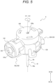
- Fig. 5 is a perspective view of the cannula port 6 alone.
- Fig. 6 is an exploded perspective view of the cannula port 6.
- Fig. 7 is a cross-sectional view of the cannula port 6 alone.
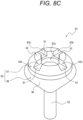
- Figs. 8A to 8C are diagrams illustrating modifications of a fixing member 83.
- Fig. 9 is a diagram illustrating another modification of the fixing member 83.
- Figs. 10A to 10D are explanatory diagrams illustrating an outline of steps in which the cannula 81 of the cannula port 6 is inserted and indwelled in the living body.
- Fig. 10A to 10D are explanatory diagrams illustrating an outline of steps in which the cannula 81 of the cannula port 6 is inserted and indwelled in the living body.
- FIG. 10A is a diagram illustrating a state before the cannula 81 of the cannula port 6 is inserted into the living body.
- Fig. 10B is a diagram illustrating a step of inserting the cannula 81 and an inner needle 200 into the living body from the state illustrated in Fig. 10A .
- Fig. 10C is a diagram illustrating a step of removing the inner needle 200 from the cannula 81 from the state illustrated in Fig. 10B .
- Fig. 10D is a diagram illustrating a step of attaching the device main body 2 to the base main body 70 from the state illustrated in Fig. 10C .
- a puncture device is not illustrated in Figs. 10A to 10D .
- the cannula port 6 includes the cannula 81 to be inserted into a living body.
- the cannula port 6 is configured to be attachable to the base main body 70.
- the cannula port 6 is attached to the base main body 70 in a state where the adhesive sheet 71 of the base main body 70 is attached to a living body surface BS.
- the cannula 81 of the cannula port 6 penetrates the base main body 70, is inserted into the living body from the living body surface BS, and is indwelled in this state. Attachment of the cannula port 6 to the base main body 70 and insertion of the cannula 81 into the living body can be performed using, for example, a puncture device (not illustrated).
- the puncture device inserts the cannula 81 into the living body together with the inner needle 200 inserted into the cannula 81.
- the inner needle 200 is removed from the living body after the cannula 81 is inserted and indwelled in the living body.
- Fig. 10C the inner needle 200 is removed from the living body after the cannula 81 is inserted and indwelled in the living body.
- the device main body 2 is attached to base main body 70 in this state.
- the connecting needle tube 12 (see Fig. 4 ) of the device main body 2 is connected in fluid communication with the cannula 81 of the cannula port 6. Therefore, the liquid medicine stored in the liquid medicine container 14 (see Fig. 4 ) of the device main body 2 can be administered into the living body through the liquid delivery pipe 13 (see Fig. 4 ), the connecting needle tube 12 (see Fig. 4 ), and the cannula 81.
- the cannula port 6 includes a cannula housing 82 and the fixing member 83 in addition to the cannula 81 described above.
- the cannula housing 82 includes a connecting portion 82a.
- the connecting needle tube 12 of the device main body 2 punctures the connecting portion 82a of the cannula port 6 in a state of being attached to the base main body 70 in advance.
- the connecting needle tube 12 of the device main body 2 is connected for fluid communication with the cannula 81 of the cannula port 6.
- the cannula port 6 may further include a first septum 142 and a second septum 143 as in the present embodiment.
- each part of the cannula port 6 will be described.
- the cannula 81 is made of resin and has flexibility. As described above, the cannula 81 is configured to be insertable into the living body from the living body surface. Specifically, the cannula 81 is inserted into the living body by the puncture device together with the inner needle 200 (see Figs. 10A to 10C ) inserted into the cannula 81. As described above, the inner needle 200 is removed from the living body after the cannula 81 is inserted and indwelled in the living body. In addition, the cannula 81 is removed from the living body together with the cradle device 3 after the liquid medicine administration over a predetermined period, such as several days, is completed.
- the cannula 81 includes a tube main body portion 84 and an extension portion 85.
- the tube main body portion 84 is a portion including a distal end 84a capable of puncturing a living body.
- the extension portion 85 is a funnel-shaped or flange-shaped (funnel-shaped in the present embodiment) portion extending from a proximal end 84b of the tube main body portion 84 toward the outside in a radial direction E of the tube main body portion 84. Additionally, the extension portion 85 is a portion supported and fixed to the cannula housing 82.
- the "funnel-shaped extension portion” means a tapered tube portion in which an outer peripheral surface and an inner peripheral surface are inclined with respect to an axial direction D and the outer diameter and the inner diameter are reduced toward an insertion direction D1 when a direction from the proximal end side to the distal end side of the tube main body portion 84 in the axial direction D of the tube main body portion 84 is defined as the insertion direction D1 of the tube main body portion 84.
- the "flange-shaped extension portion” means an annular hollow disk portion protruding outward in the radial direction E in a direction in which a surface orthogonal to the axial direction D extends from the proximal end 84b of the tube main body portion 84.
- the cannula housing 82 holds the cannula 81.
- the cannula housing 82 defines an accommodation space 88a that accommodates the extension portion 85 of the cannula 81 and an insertion hole 88b.
- the insertion hole 88b communicates with the accommodation space 88a. More specifically, the insertion hole 88b allows the accommodation space 88a and the external space outside the cannula housing 82 to communicate with each other.
- the tube main body portion 84 of the cannula 81 is inserted into the insertion hole 88b in a state where the extension portion 85 is accommodated in the accommodation space 88a.
- the distal end 84a of the tube main body portion 84 protrudes to the external space outside the cannula housing 82 through the insertion hole 88b.
- the fixing member 83 is located in the accommodation space 88a, and sandwiches the extension portion 85 of the cannula 81 with the cannula housing 82.
- the fixing member 83 fixes the position of the cannula 81 with respect to the cannula housing 82.
- the fixing member 83 of the present embodiment includes an inner intubation portion 92 on the puncture direction D1 side and a head portion 95 on a removal direction D2 side.
- the head portion 95 includes a head main body portion 96 and an end portion 97 continuous with the removal direction D2 side of the head main body portion 96.
- the head main body portion 96 of the present embodiment includes a tapered outer surface 90 whose diameter expands in the removal direction D2 along a funnel-shaped inner surface reduced diameter portion 89 of the cannula housing 82.
- the end portion 97 of the present embodiment includes an end surface 94 on which a groove portion 91 is formed.
- the outer diameter of the end portion 97 is smaller than the maximum outer diameter of the tapered outer surface 90 of the head main body portion 96.
- at least a part of the tapered outer surface 90 of the head main body portion 96 of the head portion 95 and the outer surface of the inner intubation portion 92 are in contact with an inner surface of the cannula 81.
- the fixing member 83 defines an internal flow path 83a in fluid communication with a cannula flow path 81a of the cannula 81. That is, the liquid medicine stored in the liquid medicine container 14 (see Fig. 4 ) of the device main body 2 flows into the cannula flow path 81a of the cannula 81 via the internal flow path 83a.
- the internal flow path 83a includes a straight portion 83a1 and a funnel portion 83a2.
- the straight portion 83a1 and the funnel portion 83a2 of the internal flow path 83a are formed by adjusting, in the axial direction D, the thickness of the fixing member 83 orthogonal to the axial direction D.
- the straight portion 83a1 extends linearly in the axial direction D of the tube main body portion 84 of the cannula 81.
- An end portion of the straight portion 83a1 in the insertion direction D1 is continuous with the cannula flow path 81a.
- the end portion of the straight portion 83a1 in the insertion direction D1 does not protrude from a holding block 138.
- the end portion of the straight portion 83a1 in the insertion direction D1 is located inside the holding block 138.
- the funnel portion 83a2 has a flow path diameter gradually increasing toward the flow path upstream side.
- the proximal end side of the straight portion 83a1 extends from the inner intubation portion 92 to the head portion 95 in cross-sectional view, and is connected to the funnel portion 83a2 in the head portion 95.
- the funnel portion 83a2 is formed in the end portion 97. Then, the end portion of the funnel portion 83a2 in the removal direction D2 is continuous with the accommodation space 88a.
- the fixing member 83 in the accommodation space 88a of the cannula housing 82 and sandwiching the extension portion 85 of the cannula 81 between the cannula housing 82 and the fixing member 83, it is possible to enhance the position fixability of the cannula 81 with respect to the cannula housing 82. Furthermore, by forming the internal flow path 83a in the fixing member 83 disposed in the accommodation space 88a, it is possible to prevent the entire accommodation space 88a from serving as a flow path of the liquid medicine. That is, it is possible to prevent the entire accommodation space 88a from becoming a dead volume in which the liquid medicine remains after the liquid medicine administration to the living body is completed. As a result, the flow path volume through which the liquid medicine can flow in the accommodation space 88a can be reduced, and as a result, the dead volume of the accommodation space 88a can be reduced.
- the internal flow path 83a of the fixing member 83 is a flow path of the liquid medicine and is a passage hole of the inner needle 200 described above (see Figs. 10A to 10C ).
- the inner needle 200 is inserted into the cannula 81 in advance before the cannula 81 is inserted into the living body. In this state, the inner needle 200 is inserted and passed through the internal flow path 83a of the fixing member 83.
- the inner needle 200 is removed from the inside of the cannula 81 after the cannula 81 is inserted and indwelled in the living body. At this time, the inner needle 200 is also removed from the internal flow path 83a of the fixing member 83.
- the internal flow path 83a of the fixing member 83 includes the funnel portion 83a2, it is possible to secure a wide insertion port of the internal flow path 83a for inserting the inner needle 200. This facilitates insertion of the inner needle 200 into the internal flow path 83a.
- the internal flow path 83a includes the straight portion 83a1 and the funnel portion 83a2, it is possible to reduce the sliding resistance between the inner surface defining the internal flow path 83a of the fixing member 83 and the outer surface of the inner needle 200 as compared with a case where the entire internal flow path 83a is configured only by the straight portion 83a1. This facilitates insertion of the inner needle 200 into the internal flow path 83a.
- the inner needle 200 can be easily removed from the internal flow path 83a.
- the internal flow path 83a of the fixing member 83 includes the straight portion 83a1 and the funnel portion 83a2, it is possible to suppress deterioration of the passability of the inner needle 200 in the internal flow path 83a.
- the internal flow path 83a includes the straight portion 83a1 and the funnel portion 83a2, the dead volume described above can be easily reduced as compared with the case where the entire internal flow path 83a is configured only by the funnel portion 83a2.
- the fixing member 83 defining the internal flow path 83a including the straight portion 83a1 and the funnel portion 83a2 in the accommodation space 88a it is possible to reduce a dead volume in which the liquid medicine remains in the accommodation space 88a and to suppress deterioration of the passability of the inner needle 200.
- the diameter of the straight portion 83a1 of the internal flow path 83a of the fixing member 83 is preferably substantially equal to the outer diameter of the inner needle 200 or slightly larger than the outer diameter of the inner needle 200 from the above-described viewpoint of reducing the dead volume and securing the function as the passage hole of the inner needle 200.
- the diameter of the straight portion 83a1 is preferably equal to or less than the maximum inner diameter of the tube main body portion 84 of the cannula 81.
- the maximum diameter of the funnel portion 83a2 of the internal flow path 83a of the fixing member 83 is preferably larger than the outer diameter of the inner needle 200 from the viewpoint of suppressing deterioration of the passability of the inner needle 200.
- the maximum diameter of the funnel portion 83a2 is preferably larger than the maximum inner diameter of the tube main body portion 84 of the cannula 81 from the viewpoint of suppressing deterioration of the passability of the inner needle 200.
- the volume of the space that becomes the flow path of the liquid medicine in the accommodation space 88a is preferably 1/2 or less, more preferably 1/4 or less, and particularly preferably 1/6 or less, compared to the volume of the space that becomes the flow path of the liquid medicine in the accommodation space 88a, in a state where the fixing member 83 is not disposed in the accommodation space 88a.
- the size of the fixing member 83 and the volume of the internal flow path 83a of the fixing member 83 satisfy the above-described volume relationship.
- the volume of the internal flow path 83a may be adjusted by adjusting, in the axial direction D, the thickness of the fixing member 83 orthogonal to the axial direction D. As a result, the dead volume in the accommodation space 88a can be easily reduced.
- the cannula housing 82 of the present embodiment includes the connecting portion 82a and a housing main body 82b.
- the housing main body 82b defines the accommodation space 88a and the insertion hole 88b.
- the connecting portion 82a is continuous with the housing main body 82b. More specifically, the connecting portion 82a of the present embodiment extends in a direction orthogonal to the axial direction D with respect to the housing main body 82b.
- the connecting portion 82a defines a connection flow path 88c that communicates with the accommodation space 88a and extends in a direction orthogonal to the axial direction D from the accommodation space 88a.
- the connecting portion 82a is configured to be connectable to the device main body 2.
- the cannula housing 82 of the present embodiment includes the holding block 138, a first cover 140, and a second cover 141.
- the holding block 138 internally defines the accommodation space 88a, the insertion hole 88b, and the connection flow path 88c described above. More specifically, the holding block 138 includes an accommodating recess 138a open in the removal direction D2.
- the accommodation space 88a is defined by the accommodating recess 138a described above.
- a through hole penetrating from a bottom surface of the accommodating recess 138a in the insertion direction D1 is formed in the holding block 138. This through hole is the above-described insertion hole 88b.
- the bottom surface of the accommodating recess 138a of the present embodiment is configured by the funnel-shaped inner surface reduced diameter portion 89. As illustrated in Fig.
- the cannula 81 is accommodated in the accommodating recess 138a of the holding block 138 from the open end of the accommodating recess 138a in the removal direction D2. Then, the tube main body portion 84 of the cannula 81 is inserted into the through hole as the insertion hole 88b until the extension portion 85 of the cannula 81 comes into contact with the bottom surface of the accommodating recess 138a. Thus, the cannula 81 can be positioned with respect to the holding block 138. Thereafter, the fixing member 83 is accommodated in the accommodating recess 138a of the holding block 138 from the open end of the accommodating recess 138a in the removal direction D2.
- the extension portion 85 of the cannula 81 is sandwiched between the fixing member 83 and the bottom surface of the accommodating recess 138a. Accordingly, the cannula 81 is fixed to the holding block 138 of the cannula housing 82.
- the removal direction D2 of the accommodating recess 138a of the holding block 138 is covered with the first cover 140 via the first septum 142. That is, as described above, after the cannula 81 is fixed to the holding block 138 using the fixing member 83, the removal direction D2 of the accommodating recess 138a of the holding block 138 is covered with the first cover 140 with the first septum 142 interposed therebetween. Furthermore, as illustrated in Fig. 7 , one end portion of the connection flow path 88c defined by the holding block 138 is continuous with the accommodation space 88a, and the other end portion of the connection flow path 88c is open to the outside.
- connection flow path 88c is covered with the second cover 141 via the second septum 143. More specifically, the holding block 138 defines a side hole extending in a direction orthogonal to the axial direction D from an inner surface side wall of the accommodating recess 138a. This side hole is the connection flow path 88c described above.
- the first cover 140 and the second cover 141 are fixed to the holding block 138. In the present embodiment, the holding block 138 and the first cover 140 constitute the housing main body 82b described above. Additionally, in the present embodiment, the holding block 138 and the second cover 141 constitute the connecting portion 82a described above.
- the above-described first cover 140 is formed with a passage hole 140a through which the above-described inner needle 200 (see Figs. 10A to 10C ) can pass.
- the inner needle 200 is inserted into the accommodation space 88a through the passage hole 140a of the first cover 140 and the first septum 142.
- the inner needle 200 is removed from the accommodation space 88a through the passage hole 140a of the first cover 140 and the first septum 142. Therefore, after the inner needle 200 is removed, the first septum 142 is closed to secure the liquid tightness of the accommodation space 88a.
- a central axis O2 of the internal flow path 83a of the fixing member 83 substantially coincides with a central axis O1 of the cannula 81.
- the central axis O2 of the internal flow path 83a of the fixing member 83 is the central axis of the straight portion 83a1 and the funnel portion 83a2.
- the central axis O1 of the cannula 81 is the central axis of the tube main body portion 84 and the extension portion 85.
- the passage hole 140a of the first cover 140 is located on the central axis O1 of the cannula 81 and on the central axis O2 of the internal flow path 83a of the fixing member 83. That is, in the present embodiment, the passage hole 140a, the internal flow path 83a, and the cannula flow path 81a are disposed so as to be aligned in a straight line in the axial direction D.
- the above-described second cover 141 is formed with a passage hole 141a through which the connecting needle tube 12 (see Fig. 4 ) of the device main body 2 can pass.
- the connecting needle tube 12 of the device main body 2 is inserted into the connection flow path 88c through the passage hole 141a of the second cover 141 and the second septum 143.
- the liquid medicine accommodated in the liquid medicine container 14 (see Fig. 4 ) of the device main body 2 can be administered into the living body through the liquid delivery pipe 13 (see Fig.
- the connecting needle tube 12 of the device main body 2 is removed from the connection flow path 88c through the passage hole 141a of the second cover 141 and the second septum 143. Therefore, after the connecting needle tube 12 is removed, the second septum 143 is closed to secure the liquid tightness of the accommodation space 88a.
- the device main body 2 and the cannula 81 are fluidly connected by the second septum 143 such as silicone rubber and the connecting needle tube 12, and simple and reliable fluid connection is possible.
- the fluid connection method between the device main body 2 and the cannula 81 is not limited thereto, and various needleless connection methods (ball valve type) are also applicable. Therefore, the internal volume of the connection flow path 88c depends on these connection methods.
- the passage hole 140a of the inner needle 200 ( Figs. 10A to 10C ) used to insert and indwell the cannula 81 into the living body and the passage hole 141a used to connect the connecting needle tube 12 of the device main body 2 are separately provided, but the present invention is not limited to this configuration. That is, the passage hole of the inner needle 200 used to insert and indwell the cannula 81 into the living body may also be used as the passage hole used to connect the connecting needle tube 12 of the device main body 2. In this case, the second septum 143, the second cover 141, and the connection flow path 88c are not provided. In addition, the connecting needle tube 12 is connected via the first septum 142.
- an inner surface of the housing main body 82b of the cannula housing 82 which defines the accommodation space 88a, includes a funnel-shaped inner surface reduced diameter portion 89 whose inner diameter is reduced in the insertion direction D1.
- the funnel-shaped inner surface reduced diameter portion 89 of the present embodiment is formed on the bottom surface of the accommodating recess 138a of the holding block 138.
- the inner surface reduced diameter portion 89 can support the funnel-shaped extension portion 85 of the cannula 81 in the removal direction D2 by coming into contact with an outer peripheral surface of the extension portion 85.
- the funnel-shaped extension portion 85 of the cannula 81 is supported by the funnel-shaped inner surface reduced diameter portion 89 of the cannula housing 82, whereby the positioning of the funnel-shaped extension portion 85 in the accommodation space 88a is facilitated. More specifically, the funnel-shaped extension portion 85 can be easily positioned in the accommodating recess 138a of the holding block 138.
- the difference between the inclination angle of an outer peripheral surface of the funnel-shaped extension portion 85 with respect to the axial direction D and the inclination angle of the inner surface reduced diameter portion 89 with respect to the axial direction D is preferably 1 degree or less.
- the "inclination angle with respect to the axial direction D" mentioned here refers to an acute inclination angle with respect to the axial direction D.
- the fixing member 83 of the present embodiment includes the funnel-shaped tapered outer surface 90 whose diameter decreases in the insertion direction D1. Then, as illustrated in Fig. 7 , the funnel-shaped extension portion 85 of the cannula 81 is sandwiched between the tapered outer surface 90 of the fixing member 83 and the inner surface reduced diameter portion 89 of the cannula housing 82.
- the tapered outer surface 90 of the fixing member 83 of the present embodiment has a shape substantially along the inner surface shape of the accommodating recess 138a described later. More specifically, the fixing member 83 of the present embodiment is disposed in a state of being inserted into the funnel-shaped extension portion 85 of the cannula 81 in the accommodation space 88a. In this state, the funnel-shaped extension portion 85 of the cannula 81 is sandwiched between the tapered outer surface 90 of the fixing member 83 and the inner surface reduced diameter portion 89 of the cannula housing 82.
- the fixing member 83 of the present embodiment includes a part not inserted into the extension portion 85 in the accommodation space 88a.
- the part of the fixing member 83 that is not inserted into the extension portion 85 in the accommodation space 88a is pressed in the insertion direction D1 by a projection portion 87a of the cannula housing 82.
- the projection portion 87a protrudes from an inner surface of the cannula housing 82 that defines the accommodation space 88a.
- the projection portion 87a is formed on an inner surface side wall of the accommodating recess 138a of the holding block 138.
- the fixing member 83 slides on the projection portion 87a and is pushed into the accommodating recess 138a in the insertion direction D1 so as to go over the projection portion 87a.
- a state in which the fixing member 83 is pressed in the insertion direction D1 by the projection portion 87a of the cannula housing 82 can be achieved.
- a state in which the fixing member 83 does not move in the removal direction D2 can be achieved by abutting on the projection portion 87a of the cannula housing 82. That is, in the present embodiment, the above-described projection portion 87a constitutes a locking portion 87 of the cannula housing 82 that locks the fixing member 83.
- the projection portion 87a as the locking portion 87 of the cannula housing 82 of the present embodiment is an annular projection extending over the entire region in a circumferential direction F of the tube main body portion 84, but is not limited to this configuration.
- the projection portion 87a may be constituted by, for example, a plurality of projections intermittently disposed in the circumferential direction F of the tube main body portion 84.
- the locking portion 87 of the cannula housing 82 is not limited to the projection portion 87a described above.
- the locking portion 87 of the cannula housing 82 may be constituted by, for example, a recess formed in an inner surface of the cannula housing 82, which defines the accommodation space 88a.
- Examples of the recess formed in the inner surface of the cannula housing 82 that defines the accommodation space 88a include an annular groove extending over the entire region in the circumferential direction F of the tube main body portion 84. That is, the fixing member 83 is configured such that a part thereof enters an annular groove formed in the inner surface of the cannula housing 82 that defines the accommodation space 88a. As a result, a state in which the fixing member 83 is pressed in the insertion direction D1 and a state in which the fixing member 83 does not move in the removal direction D2 may be achieved.
- the removal direction D2 of the fixing member 83 is covered with the first septum 142. More specifically, the first septum 142 is disposed adjacent to the fixing member 83 so as to cover the removal direction D2 of the fixing member 83 in the accommodation space 88a of the cannula housing 82. In particular, it is preferable that an edge portion around an opening end in the removal direction D2 of the internal flow path 83a as the end surface 94 in the removal direction D2 of the fixing member 83 is in contact with or close to the first septum 142.
- “Close” means, for example, being disposed with a gap of 1 mm or less.
- the puncture position of the connecting needle tube 12 in the first septum 142 can be kept substantially constant. That is, even when insertion and removal of the connecting needle tube 12 with respect to the first septum 142 are repeated, such as when the device main body 2 is attached to and detached from the cradle device 3, it is possible to suppress formation of a plurality of puncture marks in the first septum 142. Therefore, it is possible to suppress a decrease in liquid tightness of the accommodation space 88a due to the first septum 142.
- the end surface 94 of the fixing member 83 in the removal direction D2 is disposed in contact with or close to the first septum 142.
- the fixing member 83 preferably defines a communication flow path 83b that allows the connection flow path 88c to communicate with the internal flow path 83a.
- the end portion 97 of the fixing member 83 of the present embodiment includes the groove portion 91 formed in the end surface 94 in the removal direction D2 facing the first septum 142. More specifically, a plurality of (six in the present embodiment) groove portions 91 are formed at intervals in the circumferential direction F at an edge portion around the opening end in the removal direction D2 of the internal flow path 83a as the end surface 94 in the removal direction D2 of the fixing member 83 of the present embodiment.
- the groove portion 91 communicates with the connection flow path 88c outside in the radial direction E.
- the groove portion 91 communicates with the internal flow path 83a inside in the radial direction E.
- the liquid medicine supplied from the device main body 2 to the connection flow path 88c can flow into the internal flow path 83a through the groove space defined by the groove portion 91. That is, in the present embodiment, the groove space defined by the groove portion 91 constitutes the communication flow path 83b described above.
- the fixing member 83 includes the six groove portions 91, but the present invention is not limited to this configuration.
- the number of the groove portions 91 of the fixing member 83 may be only one as illustrated in Fig. 8A , or may be less or more than six (two in Fig. 8B and four in Fig. 8C ) as illustrated in Figs. 8B and 8C .
- the fixing member 83 of the present embodiment includes the inner intubation portion 92 to be inserted into the tube main body portion 84 of the cannula 81.
- the inner intubation portion 92 internally defines a part of the straight portion 83a1 of the internal flow path 83a described above.
- the inner intubation portion 92 may be disposed such that its outer surface is in contact with the inner surface of the tube main body portion 84 of the cannula 81. Since the fixing member 83 includes the inner intubation portion 92, bending of the tube main body portion 84 of the cannula 81 can be suppressed.
- the fixing member 83 may be made of metal or resin.
- the fixing member 83 is preferably made of resin.
- the resin inner intubation portion 92 easily follows bending deformation of the tube main body portion 84 of the resin cannula 81 as compared with a metal inner intubation portion. That is, even if the tube main body portion 84 of the resin cannula 81 is bent and deformed by, for example, body motion or the like, the resin inner intubation portion 92 is easily deformed following the deformation of the tube main body portion 84.
- the fixing member 83 is made of resin, for example, the fixing member 83 does not become an obstacle in X-ray inspection or the like.
- the tube main body portion 84 of the cannula 81 may be sandwiched between the inner intubation portion 92 of the fixing member 83 and the inner surface of the cannula housing 82 that defines the insertion hole 88b.
- the inner intubation portion 92 of the fixing member 83 of the present embodiment may be a caulking pin that clamps the tube main body portion 84 with the inner surface of the cannula housing 82 that defines the insertion hole 88b.
- the cannula 81 may be configured such that, not only the extension portion 85 described above, but also the tube main body portion 84 is sandwiched between the cannula housing 82 and the fixing member 83. In this manner, the position fixability of the cannula 81 with respect to the cannula housing 82 can be further improved.
- the cannula housing 82 of the present embodiment includes a cylindrical portion 93 protruding in the insertion direction D1. Then, the insertion hole 88b is defined inside the cylindrical portion 93. Therefore, the tube main body portion 84 may be sandwiched between an outer surface of the inner intubation portion 92 of the fixing member 83 and an inner surface of the cylindrical portion 93 of the cannula housing 82.
- the inner diameter and the outer diameter of the proximal side portion are larger than the inner diameter and the outer diameter of the distal side portion.
- the proximal side portion of the tube main body portion 84 is a part where the inner intubation portion 92 is inserted and the periphery thereof is covered with the cylindrical portion 93.
- the distal side portion of the tube main body portion 84 is a part that is located in the insertion direction D1 from the proximal side portion and can be inserted into the living body. Note, however, that the tube main body portion 84 is not limited to the configuration of the present embodiment.
- the inner diameter and the outer diameter of the proximal side portion of the tube main body portion 84 do not need to be larger than the inner diameter and the outer diameter of the distal side portion.
- the inner intubation portion 92 may include a tube portion 92a and a protrusion portion 92b protruding in the radial direction from the tube portion 92a. Since the inner intubation portion 92 includes the protrusion portion 92b, the tube main body portion 84 can be more firmly clamped.
- the protrusion portion 92b illustrated in Fig. 9 is an annular protrusion extending over the entire circumferential direction of the tube portion 92a, but is not limited to this configuration.
- the protrusion portion 92b may be, for example, a spiral protrusion extending over the entire circumferential direction of the tube portion 92a.
- protrusion portions 92b illustrated in Fig. 9 are disposed at different positions in the axial direction of the tube portion 92a, the number of protrusion portions 92b is not particularly limited. Only one protrusion portion 92b may be provided, or three or more protrusions may be disposed in different positions in the axial direction of the tube portion 92a.
- the fixing member 83 of the present embodiment includes the inner intubation portion 92, but is not limited to this configuration.
- the fixing member 83 may be configured to be accommodated only in the accommodation space 88a without including the inner intubation portion 92.
- the present disclosure relates to a cannula port, a cradle device, and a liquid medicine administration device.
Landscapes
- Health & Medical Sciences (AREA)
- Heart & Thoracic Surgery (AREA)
- Vascular Medicine (AREA)
- Engineering & Computer Science (AREA)
- Anesthesiology (AREA)
- Biomedical Technology (AREA)
- Hematology (AREA)
- Life Sciences & Earth Sciences (AREA)
- Animal Behavior & Ethology (AREA)
- General Health & Medical Sciences (AREA)
- Public Health (AREA)
- Veterinary Medicine (AREA)
- Dermatology (AREA)
- Infusion, Injection, And Reservoir Apparatuses (AREA)
Abstract
Description
- The present disclosure relates to a cannula port, a cradle device, and a liquid medicine administration device.
- In recent years, a treatment method of continuously administering a liquid medicine into the body of a patient by subcutaneous injection, intravenous injection, or the like has been performed. For example, as a treatment method for a diabetic patient, a treatment of continuously injecting a trace amount of insulin into the body of the patient is performed. In this treatment method, in order to administer insulin as a liquid medicine to a patient throughout the day, an insulin pump is used as a portable liquid medicine administration device that can be fixed and carried on the patient's body or clothes.
Patent Literature 1 discloses a cannula unit used for this type of insulin pump. - The cannula unit described in
Patent Literature 1 includes a cannula and a housing.Patent Literature 1 discloses a configuration in which a cannula is sandwiched between a bore of a first portion of a housing and a bush of a second portion of the housing. - Patent Literature 1:
WO 2018/033614 - As in the cannula unit described in
Patent Literature 1, the cannula is sandwiched and fixed by the first portion and the second portion of the housing, whereby the cannula is firmly fixed to the housing. However, when the cannula is fixed to the first portion of the housing, if the second portion including the bush as the fixing member described inPatent Literature 1 is adopted, the dead volume in which the liquid medicine is retained in the housing tends to be large. Specifically, inPatent Literature 1, a space in the bush of the second portion becomes the dead volume in which the liquid medicine remains after completion of the liquid medicine administration to the living body. Therefore, it is not preferable from the viewpoint of saving the liquid medicine. - On the other hand, the space in the bush of the second portion of
Patent Literature 1 is used not only as a flow path of the liquid medicine but also as a passage hole of an inner needle. The inner needle is inserted into the living body together with the cannula in a state of being inserted into the cannula, and is removed from the cannula after the cannula is indwelled in the living body. When the diameter of the space in the bush of the second portion ofPatent Literature 1 is reduced for the purpose of reducing the dead volume described above, it is difficult to insert the inner needle into the space in the bush of the second portion. Even if the inner needle can be inserted into the space in the bush of the second portion, it may be difficult to insert the inner needle into the space in the bush of the second portion due to the sliding resistance between an outer surface of the inner needle and an inner surface of the bush. Furthermore, when removing the inner needle from the cannula after the cannula is indwelled in the living body, the sliding resistance between the outer surface of the inner needle and the inner surface of the bush may increase. As described above, when the diameter of the space in the bush in the second portion ofPatent Literature 1 is reduced, the passability of the inner needle becomes a problem. - An object of the present disclosure is to provide a cannula port, a cradle device, and a liquid medicine administration device capable of reducing a dead volume in which a liquid medicine remains and suppressing deterioration of passability of an inner needle.
- A cannula port according to a first aspect of the present disclosure is a cannula port including:
- (1)
- a cannula that is insertable into a living body from a living body surface;
- a cannula housing that holds the cannula; and
- a fixing member that fixes a position of the cannula with respect to the cannula housing, in which:
- the cannula includes
- a tube main body portion including a distal end capable of puncturing the living body, and
- a funnel-shaped or flange-shaped extension portion extending from a proximal end of the tube main body portion toward an outside in a radial direction of the tube main body portion;
- the cannula housing defines
- an accommodation space that accommodates the extension portion of the cannula, and
- an insertion hole communicating with the accommodation space and through which the tube main body portion of the cannula is inserted;
- the fixing member is located in the accommodation space, and fixes the position of the cannula with respect to the cannula housing by sandwiching the extension portion of the cannula with the cannula housing;
- the fixing member defines an internal flow path in fluid communication with the cannula; and
- the internal flow path includes
- a straight portion linearly extending in an axial direction of the tube main body portion, and
- a funnel portion connected to a flow path upstream side of the straight portion and having a flow path diameter gradually increasing toward the flow path upstream side.
- A cannula port according to an embodiment of the present disclosure is
(2)
the cannula port according to (1), further including a septum disposed adjacent to the fixing member so as to cover a removal direction of the fixing member in the accommodation space of the cannula housing when a direction from the distal end toward the proximal end in the axial direction of the tube main body portion is the removal direction. - A cannula port according to an embodiment of the present disclosure is
(3)
the cannula port according to (2), in which: - the cannula housing includes
- a housing main body that defines the accommodation space and the insertion hole, and
- a connecting portion that is connected to the housing main body and is connected to a device main body including a liquid medicine container capable of storing a liquid medicine;
- the connecting portion defines a connection flow path communicating with the accommodation space and extending in a direction orthogonal to the axial direction from the accommodation space; and
- the fixing member defines a communication flow path that allows the connection flow path to communicate with the internal flow path.
- A cannula port according to an embodiment of the present disclosure is
(4) - the cannula port according to (3), in which
- the fixing member includes a groove portion formed in an end surface in the removal direction facing the septum, and
- the communication flow path includes a groove space defined by the groove portion.
- A cannula port according to an embodiment of the present disclosure is
(5)
the cannula port according to any one of (1) to (4), in which the cannula housing includes, on an inner surface that defines the accommodation space, a locking portion that locks the fixing member. - A cannula port according to an embodiment of the present disclosure is
(6) - the cannula port according to (5), in which the locking portion is
- a projection portion protruding from the inner surface defining the accommodation space, or
- a recess formed in the inner surface defining the accommodation space.
- A cradle device according to a second aspect of the present disclosure is
(7) - a cradle device including
- the cannula port according to any one of (1) to (6), and
- a base body to which the cannula port is attachable, the base body being attachable to the living body surface.
- A liquid medicine administration device according to a third aspect of the present disclosure is
(8) - a liquid medicine administration device including
- the cradle device according to (7), and
- a device main body including a liquid medicine container capable of storing a liquid medicine and attachable to and detachable from the cradle device.
- According to the present disclosure, it is possible to provide a cannula port, a cradle device, and a liquid medicine administration device capable of reducing a dead volume in which a liquid medicine remains and suppressing deterioration of passability of an inner needle.
-
-
Fig. 1 is a perspective view illustrating a liquid medicine administration device. -
Fig. 2 is a perspective view illustrating a state before a device main body and a cradle device of the liquid medicine administration device are attached to each other. -
Fig. 3 is a plan view illustrating the cradle device. -
Fig. 4 is an explanatory view illustrating a state in the middle of attaching the device main body to the cradle device. -
Fig. 5 is a perspective view of a cannula port alone. -
Fig. 6 is an exploded perspective view of the cannula port. -
Fig. 7 is a cross-sectional view of the cannula port. -
Fig. 8A is a diagram illustrating a modification of a fixing member. -
Fig. 8B is a diagram illustrating a modification of the fixing member. -
Fig. 8C is a diagram illustrating a modification of the fixing member. -
Fig. 9 is a diagram illustrating a modification of the fixing member. -
Fig. 10A is a diagram illustrating a state before a cannula of a cannula port is inserted into a living body. -
Fig. 10B is a diagram illustrating a step of inserting the cannula and an inner needle into the living body from the state illustrated inFig. 10A . -
Fig. 10C is a diagram illustrating a step of removing the inner needle from the cannula from the state illustrated inFig. 10B . -
Fig. 10D is a diagram illustrating a step of attaching the device main body to the base main body from the state illustrated inFig. 10C . - Hereinafter, embodiments of a cannula port, a cradle device, and a liquid medicine administration device according to the present disclosure will be described by way of example with reference to the drawings. In the drawings, the same components are denoted by the same reference numerals.
- First, a liquid
medicine administration device 1 as an embodiment of a liquid medicine administration device according to the present disclosure will be described with reference toFigs. 1 to 4 .Fig. 1 is a perspective view illustrating the liquidmedicine administration device 1.Fig. 2 is a perspective view illustrating a state before a devicemain body 2 and acradle device 3 of the liquidmedicine administration device 1 are attached to each other.Fig. 3 is a plan view illustrating thecradle device 3.Fig. 4 is an explanatory view illustrating a state where the devicemain body 2 is being attached to thecradle device 3. - As illustrated in
Fig. 1 , the liquidmedicine administration device 1 is a portable insulin pump for continuously administering a liquid medicine into a living body such as a patient like a patch-type or tube-type insulin pump and other portable liquid medicine administration devices. The liquid medicine administration device according to the present disclosure is not limited to the insulin pump illustrated inFig. 1 , but in the present embodiment, an insulin pump as an example of the liquid medicine administration device according to the present disclosure will be described by way of example. The liquidmedicine administration device 1 includes the devicemain body 2 and thecradle device 3 configured to be attachable to and detachable from the devicemain body 2. Thecradle device 3 includes acannula port 6 described later. Thecannula port 6 includes acannula 81 that can be inserted into the living body from the surface of the living body. - As illustrated in
Figs. 1 ,2 , and4 , the devicemain body 2 includes ahollow housing 11. Additionally, as illustrated inFig. 4 , the devicemain body 2 includes a connectingneedle tube 12. Furthermore, as illustrated inFig. 4 , the devicemain body 2 includes aliquid delivery pipe 13, aliquid medicine container 14, and adrive unit 15 in thehousing 11. Theliquid medicine container 14 stores a liquid medicine to be administered into a living body. One end portion of theliquid delivery pipe 13 is connected to theliquid medicine container 14. The other end portion of theliquid delivery pipe 13 is connected to the connectingneedle tube 12. Thedrive unit 15 can send the liquid medicine stored in theliquid medicine container 14 into theliquid delivery pipe 13. The liquid medicine sent into theliquid delivery pipe 13 from theliquid medicine container 14 is discharged from the devicemain body 2 through the connectingneedle tube 12. The connectingneedle tube 12 is punctured into a connectingportion 82a of thecannula port 6 described later in a state where the devicemain body 2 is attached to thecradle device 3. As a result, theliquid delivery pipe 13 and the connectingportion 82a are connected via the connectingneedle tube 12. - Hereinafter, for convenience of description, a direction in which the device
main body 2 is attached to and detached from thecradle device 3 will be referred to as an attaching and detaching direction A. Of the attaching and detaching direction A, a direction in which the devicemain body 2 is moved with respect to thecradle device 3 at the time of attachment is referred to as an attachment direction A1. Of the attaching and detaching direction A, a direction in which the devicemain body 2 is moved with respect to thecradle device 3 at the time of detachment is referred to as a detachment direction A2. Additionally, a direction orthogonal to the attaching and detaching direction A and also orthogonal to a direction in which the devicemain body 2 and thecradle device 3 overlap with each other is referred to as a device width direction B. Moreover, a direction in which the devicemain body 2 and thecradle device 3 overlap each other, that is, a direction orthogonal to the attaching and detaching direction A and the device width direction B is referred to as a device height direction C. - The
housing 11 may be formed in a flat and substantially rectangular parallelepiped shape having curved corners. Thehousing 11 of the present embodiment includes atop plate portion 21, abottom plate portion 22, afront plate portion 23, arear plate portion 24, a firstside plate portion 25, and a secondside plate portion 26. Thetop plate portion 21 and thebottom plate portion 22 face each other in the device height direction C. Thetop plate portion 21 is formed in a substantially rectangular shape with curved corners. Additionally, the central portion of thetop plate portion 21 bulges toward the side opposite to thebottom plate portion 22 in the device height direction C. - The
front plate portion 23 is substantially vertically continuous to one end portion of thetop plate portion 21 in the attaching and detaching direction A, and therear plate portion 24 is substantially vertically continuous to the other end portion of thetop plate portion 21 in the attaching and detaching direction A. Thefront plate portion 23 and therear plate portion 24 face each other in the attaching and detaching direction A. The firstside plate portion 25 is substantially vertically continuous to one end portion of thetop plate portion 21 in the device width direction B, and the secondside plate portion 26 is substantially vertically continuous to the other end portion of thetop plate portion 21 in the device width direction B. - A sliding
groove 32 that accommodates a slidingrail 53, which will be described later, of thecradle device 3, and slides with the slidingrail 53 is formed in thebottom plate portion 22. In addition, thebottom plate portion 22 may be provided with, for example, an attachment detection switch capable of detecting a state in which the devicemain body 2 is attached to thecradle device 3. - As illustrated in
Fig. 4 , thehousing 11 defines aport accommodating portion 27 capable of accommodating thecannula port 6 described later in a state where the devicemain body 2 is attached to thecradle device 3. Theport accommodating portion 27 is formed in a corner where thebottom plate portion 22, the firstside plate portion 25, and thefront plate portion 23 in thehousing 11 are continuous. Theport accommodating portion 27 is a recess recessed by a predetermined length from thebottom plate portion 22 toward thetop plate portion 21 along the device height direction C. - A
tubular connection port 28 is formed in aside wall 27a defining the detachment direction A2 of theport accommodating portion 27. Theconnection port 28 protrudes from theside wall 27a in the attachment direction A1. The connectingneedle tube 12 is disposed in the cylindrical hole of theconnection port 28. The connectingneedle tube 12 protrudes from theside wall 27a in the attachment direction A1. - The first
side plate portion 25 and the secondside plate portion 26 of thehousing 11 may be provided with a locking portion that engages with a receiving portion of thecradle device 3 when the devicemain body 2 is attached to thecradle device 3 and can maintain an attached state of the devicemain body 2 and thecradle device 3. The locking portion and the receiving portion may include, for example, a locking claw portion and a recess into which the locking claw portion is fitted. The locked state of the devicemain body 2 and thecradle device 3 by the locking portion and the receiving portion is configured to be releasable by the operation of the operator. Thus, the devicemain body 2 is configured to be attachable to and detachable from thecradle device 3. However, specific configurations of the locking portion and the receiving portion are not particularly limited. That is, the locking portion and the receiving portion are not limited to the locking claw portion and the recess described above. - As illustrated in
Figs. 1 to 4 , thecradle device 3 of the present embodiment includes abase body 5 and acannula port 6. - The
base body 5 is configured to be attachable to a surface of a living body. Furthermore, thebase body 5 is configured such that thecannula port 6 can be attached thereto. Furthermore, thebase body 5 is configured such that the devicemain body 2 is attachable thereto and detachable therefrom. - More specifically, the
base body 5 of the present embodiment includes a basemain body 70, anadhesive sheet 71, and releasepaper 72. - The base
main body 70 of the present embodiment includes a substantially flat plate-shapedplacement portion 41, a firstside wall portion 42, a secondside wall portion 43, and a thirdside wall portion 44. As illustrated inFigs. 2 to 4 , the basemain body 70 of the present embodiment defines anaccommodation space 70a capable of accommodating the devicemain body 2. Theaccommodation space 70a is a space surrounded by theplacement portion 41, the firstside wall portion 42, the secondside wall portion 43, and the thirdside wall portion 44. - The
placement portion 41 is formed in a substantially rectangular shape with curved corners. When the devicemain body 2 is attached to thecradle device 3, thebottom plate portion 22 of thehousing 11 of the devicemain body 2 is placed on theplacement portion 41. - An
attachment portion 51 and a slidingrail 53 are provided on anupper surface 41a of theplacement portion 41 on theaccommodation space 70a side. Theattachment portion 51 is formed in an end portion of theplacement portion 41 in the attachment direction A1 and in one end portion of theplacement portion 41 in the device width direction B. Theattachment portion 51 is configured such that thecannula port 6 described later can be attached thereto. Furthermore, theattachment portion 51 is provided with an insertion hole through which thecannula 81 of thecannula port 6 described later is inserted. - The sliding
rail 53 is formed in an intermediate portion of theupper surface 41a of theplacement portion 41 in the device width direction B. The slidingrail 53 extends from one end portion to the other end portion of theupper surface 41a of theplacement portion 41 in the attaching and detaching direction A. When the devicemain body 2 is attached to thecradle device 3, the slidinggroove 32 of the devicemain body 2 is slidably fitted into the slidingrail 53. - The first
side wall portion 42 is substantially vertically continuous to one end portion of theplacement portion 41 in the device width direction B, and the secondside wall portion 43 is substantially vertically continuous to the other end portion of theplacement portion 41 in the device width direction B. Then, the thirdside wall portion 44 is substantially vertically continuous with the end portion of theplacement portion 41 in the attachment direction A1. Therefore, three of the four sides of theplacement portion 41 are continuous with the firstside wall portion 42, the secondside wall portion 43, and the thirdside wall portion 44. Then, no side wall portion is continuous with the end portion of theplacement portion 41 in the detachment direction A2. That is, the end portion of theaccommodation space 70a in the detachment direction A2 is open. The devicemain body 2 is inserted into theaccommodation space 70a from the open end portion of theaccommodation space 70a in the detachment direction A2, and is attached to the basemain body 70. - The
adhesive sheet 71 is configured to be attachable to the skin of a patient as a living body surface. Theadhesive sheet 71 is attached to alower surface 41b (seeFig. 2 ) of theplacement portion 41 of the basemain body 70 on a side opposite to theupper surface 41a. An opening through which thecannula 81 of thecannula port 6 described later passes is formed in theadhesive sheet 71. - Furthermore, the
adhesive sheet 71 is formed of a flexible member, and a surface of theadhesive sheet 71 on a side opposite to theplacement portion 41 side is anadhesive surface 71a that can be attached to a living body surface. Theadhesive surface 71a of theadhesive sheet 71 is covered with therelease paper 72 in a state before being adhered to the living body surface. That is, thecradle device 3 peels therelease paper 72 from theadhesive sheet 71 to expose theadhesive surface 71a of theadhesive sheet 71, so that thecradle device 3 can be attached to the living body surface. - Next, the
cannula port 6 will be described with reference toFigs. 2 to 10D .Fig. 5 is a perspective view of thecannula port 6 alone.Fig. 6 is an exploded perspective view of thecannula port 6.Fig. 7 is a cross-sectional view of thecannula port 6 alone.Figs. 8A to 8C are diagrams illustrating modifications of a fixingmember 83.Fig. 9 is a diagram illustrating another modification of the fixingmember 83.Figs. 10A to 10D are explanatory diagrams illustrating an outline of steps in which thecannula 81 of thecannula port 6 is inserted and indwelled in the living body.Fig. 10A is a diagram illustrating a state before thecannula 81 of thecannula port 6 is inserted into the living body.Fig. 10B is a diagram illustrating a step of inserting thecannula 81 and aninner needle 200 into the living body from the state illustrated inFig. 10A .Fig. 10C is a diagram illustrating a step of removing theinner needle 200 from thecannula 81 from the state illustrated inFig. 10B .Fig. 10D is a diagram illustrating a step of attaching the devicemain body 2 to the basemain body 70 from the state illustrated inFig. 10C . A puncture device is not illustrated inFigs. 10A to 10D . - The
cannula port 6 includes thecannula 81 to be inserted into a living body. First, an outline of steps in which thecannula 81 of thecannula port 6 is inserted and indwelled in a living body will be described with reference toFigs. 10A to 10D . As described above, thecannula port 6 is configured to be attachable to the basemain body 70. As illustrated inFigs. 10A and10B , thecannula port 6 is attached to the basemain body 70 in a state where theadhesive sheet 71 of the basemain body 70 is attached to a living body surface BS. At this time, thecannula 81 of thecannula port 6 penetrates the basemain body 70, is inserted into the living body from the living body surface BS, and is indwelled in this state. Attachment of thecannula port 6 to the basemain body 70 and insertion of thecannula 81 into the living body can be performed using, for example, a puncture device (not illustrated). The puncture device inserts thecannula 81 into the living body together with theinner needle 200 inserted into thecannula 81. As illustrated inFig. 10C , theinner needle 200 is removed from the living body after thecannula 81 is inserted and indwelled in the living body. As illustrated inFig. 10D , the devicemain body 2 is attached to basemain body 70 in this state. At this time, the connecting needle tube 12 (seeFig. 4 ) of the devicemain body 2 is connected in fluid communication with thecannula 81 of thecannula port 6. Therefore, the liquid medicine stored in the liquid medicine container 14 (seeFig. 4 ) of the devicemain body 2 can be administered into the living body through the liquid delivery pipe 13 (seeFig. 4 ), the connecting needle tube 12 (seeFig. 4 ), and thecannula 81. - As illustrated in
Figs. 6 and7 , thecannula port 6 includes acannula housing 82 and the fixingmember 83 in addition to thecannula 81 described above. As will be described in detail later, thecannula housing 82 includes a connectingportion 82a. When the devicemain body 2 is attached to the basemain body 70, the connectingneedle tube 12 of the devicemain body 2 punctures the connectingportion 82a of thecannula port 6 in a state of being attached to the basemain body 70 in advance. Thereby, as described above, the connectingneedle tube 12 of the devicemain body 2 is connected for fluid communication with thecannula 81 of thecannula port 6. As will be described in detail later, thecannula port 6 may further include afirst septum 142 and asecond septum 143 as in the present embodiment. Hereinafter, each part of thecannula port 6 will be described. - The
cannula 81 is made of resin and has flexibility. As described above, thecannula 81 is configured to be insertable into the living body from the living body surface. Specifically, thecannula 81 is inserted into the living body by the puncture device together with the inner needle 200 (seeFigs. 10A to 10C ) inserted into thecannula 81. As described above, theinner needle 200 is removed from the living body after thecannula 81 is inserted and indwelled in the living body. In addition, thecannula 81 is removed from the living body together with thecradle device 3 after the liquid medicine administration over a predetermined period, such as several days, is completed. - The
cannula 81 includes a tubemain body portion 84 and anextension portion 85. The tubemain body portion 84 is a portion including adistal end 84a capable of puncturing a living body. Theextension portion 85 is a funnel-shaped or flange-shaped (funnel-shaped in the present embodiment) portion extending from aproximal end 84b of the tubemain body portion 84 toward the outside in a radial direction E of the tubemain body portion 84. Additionally, theextension portion 85 is a portion supported and fixed to thecannula housing 82. Here, the "funnel-shaped extension portion" means a tapered tube portion in which an outer peripheral surface and an inner peripheral surface are inclined with respect to an axial direction D and the outer diameter and the inner diameter are reduced toward an insertion direction D1 when a direction from the proximal end side to the distal end side of the tubemain body portion 84 in the axial direction D of the tubemain body portion 84 is defined as the insertion direction D1 of the tubemain body portion 84. Moreover, the "flange-shaped extension portion" means an annular hollow disk portion protruding outward in the radial direction E in a direction in which a surface orthogonal to the axial direction D extends from theproximal end 84b of the tubemain body portion 84. - As illustrated in
Fig. 7 , thecannula housing 82 holds thecannula 81. As illustrated inFig. 7 , thecannula housing 82 defines anaccommodation space 88a that accommodates theextension portion 85 of thecannula 81 and aninsertion hole 88b. Theinsertion hole 88b communicates with theaccommodation space 88a. More specifically, theinsertion hole 88b allows theaccommodation space 88a and the external space outside thecannula housing 82 to communicate with each other. The tubemain body portion 84 of thecannula 81 is inserted into theinsertion hole 88b in a state where theextension portion 85 is accommodated in theaccommodation space 88a. Thedistal end 84a of the tubemain body portion 84 protrudes to the external space outside thecannula housing 82 through theinsertion hole 88b. - As illustrated in
Fig. 7 , the fixingmember 83 is located in theaccommodation space 88a, and sandwiches theextension portion 85 of thecannula 81 with thecannula housing 82. Thus, the fixingmember 83 fixes the position of thecannula 81 with respect to thecannula housing 82. More specifically, the fixingmember 83 of the present embodiment includes aninner intubation portion 92 on the puncture direction D1 side and ahead portion 95 on a removal direction D2 side. Thehead portion 95 includes a headmain body portion 96 and anend portion 97 continuous with the removal direction D2 side of the headmain body portion 96. The headmain body portion 96 of the present embodiment includes a taperedouter surface 90 whose diameter expands in the removal direction D2 along a funnel-shaped inner surface reduceddiameter portion 89 of thecannula housing 82. Theend portion 97 of the present embodiment includes anend surface 94 on which agroove portion 91 is formed. The outer diameter of theend portion 97 is smaller than the maximum outer diameter of the taperedouter surface 90 of the headmain body portion 96. As will be described in detail later, in the present embodiment, at least a part of the taperedouter surface 90 of the headmain body portion 96 of thehead portion 95 and the outer surface of theinner intubation portion 92 are in contact with an inner surface of thecannula 81. - As illustrated in
Figs. 6 and7 , the fixingmember 83 defines aninternal flow path 83a in fluid communication with acannula flow path 81a of thecannula 81. That is, the liquid medicine stored in the liquid medicine container 14 (seeFig. 4 ) of the devicemain body 2 flows into thecannula flow path 81a of thecannula 81 via theinternal flow path 83a. As illustrated inFig. 7 , theinternal flow path 83a includes a straight portion 83a1 and a funnel portion 83a2. The straight portion 83a1 and the funnel portion 83a2 of theinternal flow path 83a are formed by adjusting, in the axial direction D, the thickness of the fixingmember 83 orthogonal to the axial direction D. The straight portion 83a1 extends linearly in the axial direction D of the tubemain body portion 84 of thecannula 81. An end portion of the straight portion 83a1 in the insertion direction D1 is continuous with thecannula flow path 81a. The end portion of the straight portion 83a1 in the insertion direction D1 does not protrude from a holdingblock 138. The end portion of the straight portion 83a1 in the insertion direction D1 is located inside the holdingblock 138. As a result, even if the liquidmedicine administration device 1 is pressed toward the skin in a state where the liquidmedicine administration device 1 is attached, it is possible to reduce stimulation to the skin around the insertion portion of thecannula 81. Additionally, when a direction from the distal end side toward the proximal end side of the tubemain body portion 84 in the axial direction D of the tubemain body portion 84 is defined as the removal direction D2 of the tubemain body portion 84, an end portion of the straight portion 83a1 in the removal direction D2 is continuous with the funnel portion 83a2. That is, the funnel portion 83a2 is continuous with the flow path upstream side of the straight portion 83a1. The funnel portion 83a2 has a flow path diameter gradually increasing toward the flow path upstream side. Here, the proximal end side of the straight portion 83a1 extends from theinner intubation portion 92 to thehead portion 95 in cross-sectional view, and is connected to the funnel portion 83a2 in thehead portion 95. Preferably, the funnel portion 83a2 is formed in theend portion 97. Then, the end portion of the funnel portion 83a2 in the removal direction D2 is continuous with theaccommodation space 88a. - In this manner, by disposing the fixing
member 83 in theaccommodation space 88a of thecannula housing 82 and sandwiching theextension portion 85 of thecannula 81 between thecannula housing 82 and the fixingmember 83, it is possible to enhance the position fixability of thecannula 81 with respect to thecannula housing 82. Furthermore, by forming theinternal flow path 83a in the fixingmember 83 disposed in theaccommodation space 88a, it is possible to prevent theentire accommodation space 88a from serving as a flow path of the liquid medicine. That is, it is possible to prevent theentire accommodation space 88a from becoming a dead volume in which the liquid medicine remains after the liquid medicine administration to the living body is completed. As a result, the flow path volume through which the liquid medicine can flow in theaccommodation space 88a can be reduced, and as a result, the dead volume of theaccommodation space 88a can be reduced. - Furthermore, the
internal flow path 83a of the fixingmember 83 is a flow path of the liquid medicine and is a passage hole of theinner needle 200 described above (seeFigs. 10A to 10C ). Specifically, theinner needle 200 is inserted into thecannula 81 in advance before thecannula 81 is inserted into the living body. In this state, theinner needle 200 is inserted and passed through theinternal flow path 83a of the fixingmember 83. Furthermore, as described above, theinner needle 200 is removed from the inside of thecannula 81 after thecannula 81 is inserted and indwelled in the living body. At this time, theinner needle 200 is also removed from theinternal flow path 83a of the fixingmember 83. Since theinternal flow path 83a of the fixingmember 83 includes the funnel portion 83a2, it is possible to secure a wide insertion port of theinternal flow path 83a for inserting theinner needle 200. This facilitates insertion of theinner needle 200 into theinternal flow path 83a. In addition, since theinternal flow path 83a includes the straight portion 83a1 and the funnel portion 83a2, it is possible to reduce the sliding resistance between the inner surface defining theinternal flow path 83a of the fixingmember 83 and the outer surface of theinner needle 200 as compared with a case where the entireinternal flow path 83a is configured only by the straight portion 83a1. This facilitates insertion of theinner needle 200 into theinternal flow path 83a. In addition, theinner needle 200 can be easily removed from theinternal flow path 83a. As described above, since theinternal flow path 83a of the fixingmember 83 includes the straight portion 83a1 and the funnel portion 83a2, it is possible to suppress deterioration of the passability of theinner needle 200 in theinternal flow path 83a. Furthermore, since theinternal flow path 83a includes the straight portion 83a1 and the funnel portion 83a2, the dead volume described above can be easily reduced as compared with the case where the entireinternal flow path 83a is configured only by the funnel portion 83a2. - As described above, by disposing the fixing
member 83 defining theinternal flow path 83a including the straight portion 83a1 and the funnel portion 83a2 in theaccommodation space 88a, it is possible to reduce a dead volume in which the liquid medicine remains in theaccommodation space 88a and to suppress deterioration of the passability of theinner needle 200. - In particular, the diameter of the straight portion 83a1 of the
internal flow path 83a of the fixingmember 83 is preferably substantially equal to the outer diameter of theinner needle 200 or slightly larger than the outer diameter of theinner needle 200 from the above-described viewpoint of reducing the dead volume and securing the function as the passage hole of theinner needle 200. From the same viewpoint as above, the diameter of the straight portion 83a1 is preferably equal to or less than the maximum inner diameter of the tubemain body portion 84 of thecannula 81. - On the other hand, the maximum diameter of the funnel portion 83a2 of the
internal flow path 83a of the fixingmember 83 is preferably larger than the outer diameter of theinner needle 200 from the viewpoint of suppressing deterioration of the passability of theinner needle 200. In addition, the maximum diameter of the funnel portion 83a2 is preferably larger than the maximum inner diameter of the tubemain body portion 84 of thecannula 81 from the viewpoint of suppressing deterioration of the passability of theinner needle 200. - Here, in a state where the fixing
member 83 is disposed in theaccommodation space 88a, the volume of the space that becomes the flow path of the liquid medicine in theaccommodation space 88a is preferably 1/2 or less, more preferably 1/4 or less, and particularly preferably 1/6 or less, compared to the volume of the space that becomes the flow path of the liquid medicine in theaccommodation space 88a, in a state where the fixingmember 83 is not disposed in theaccommodation space 88a. In other words, it is preferable that the size of the fixingmember 83 and the volume of theinternal flow path 83a of the fixingmember 83 satisfy the above-described volume relationship. The volume of theinternal flow path 83a may be adjusted by adjusting, in the axial direction D, the thickness of the fixingmember 83 orthogonal to the axial direction D. As a result, the dead volume in theaccommodation space 88a can be easily reduced. - Hereinafter, further details of the
cannula port 6 of the present embodiment will be described. - As illustrated in
Figs. 5 to 7 , thecannula housing 82 of the present embodiment includes the connectingportion 82a and a housingmain body 82b. As illustrated inFig. 7 , the housingmain body 82b defines theaccommodation space 88a and theinsertion hole 88b. The connectingportion 82a is continuous with the housingmain body 82b. More specifically, the connectingportion 82a of the present embodiment extends in a direction orthogonal to the axial direction D with respect to the housingmain body 82b. As illustrated inFig. 7 , the connectingportion 82a defines aconnection flow path 88c that communicates with theaccommodation space 88a and extends in a direction orthogonal to the axial direction D from theaccommodation space 88a. As described above, the connectingportion 82a is configured to be connectable to the devicemain body 2. - More specifically, as illustrated in
Figs. 5 to 7 , thecannula housing 82 of the present embodiment includes the holdingblock 138, afirst cover 140, and asecond cover 141. - As illustrated in
Fig. 7 , the holdingblock 138 internally defines theaccommodation space 88a, theinsertion hole 88b, and theconnection flow path 88c described above. More specifically, the holdingblock 138 includes anaccommodating recess 138a open in the removal direction D2. Theaccommodation space 88a is defined by theaccommodating recess 138a described above. In addition, a through hole penetrating from a bottom surface of theaccommodating recess 138a in the insertion direction D1 is formed in the holdingblock 138. This through hole is the above-describedinsertion hole 88b. As will be described in detail later, the bottom surface of theaccommodating recess 138a of the present embodiment is configured by the funnel-shaped inner surface reduceddiameter portion 89. As illustrated inFig. 6 , thecannula 81 is accommodated in theaccommodating recess 138a of the holdingblock 138 from the open end of theaccommodating recess 138a in the removal direction D2. Then, the tubemain body portion 84 of thecannula 81 is inserted into the through hole as theinsertion hole 88b until theextension portion 85 of thecannula 81 comes into contact with the bottom surface of theaccommodating recess 138a. Thus, thecannula 81 can be positioned with respect to the holdingblock 138. Thereafter, the fixingmember 83 is accommodated in theaccommodating recess 138a of the holdingblock 138 from the open end of theaccommodating recess 138a in the removal direction D2. When the fixingmember 83 is pushed in the insertion direction D1, theextension portion 85 of thecannula 81 is sandwiched between the fixingmember 83 and the bottom surface of theaccommodating recess 138a. Accordingly, thecannula 81 is fixed to the holdingblock 138 of thecannula housing 82. - As illustrated in
Fig. 7 , the removal direction D2 of theaccommodating recess 138a of the holdingblock 138 is covered with thefirst cover 140 via thefirst septum 142. That is, as described above, after thecannula 81 is fixed to the holdingblock 138 using the fixingmember 83, the removal direction D2 of theaccommodating recess 138a of the holdingblock 138 is covered with thefirst cover 140 with thefirst septum 142 interposed therebetween. Furthermore, as illustrated inFig. 7 , one end portion of theconnection flow path 88c defined by the holdingblock 138 is continuous with theaccommodation space 88a, and the other end portion of theconnection flow path 88c is open to the outside. The other end portion of theconnection flow path 88c is covered with thesecond cover 141 via thesecond septum 143. More specifically, the holdingblock 138 defines a side hole extending in a direction orthogonal to the axial direction D from an inner surface side wall of theaccommodating recess 138a. This side hole is theconnection flow path 88c described above. Thefirst cover 140 and thesecond cover 141 are fixed to the holdingblock 138. In the present embodiment, the holdingblock 138 and thefirst cover 140 constitute the housingmain body 82b described above. Additionally, in the present embodiment, the holdingblock 138 and thesecond cover 141 constitute the connectingportion 82a described above. - As illustrated in
Figs. 5 to 7 , the above-describedfirst cover 140 is formed with apassage hole 140a through which the above-described inner needle 200 (seeFigs. 10A to 10C ) can pass. Theinner needle 200 is inserted into theaccommodation space 88a through thepassage hole 140a of thefirst cover 140 and thefirst septum 142. Theinner needle 200 is removed from theaccommodation space 88a through thepassage hole 140a of thefirst cover 140 and thefirst septum 142. Therefore, after theinner needle 200 is removed, thefirst septum 142 is closed to secure the liquid tightness of theaccommodation space 88a. - As illustrated in
Figs. 6 and7 , a central axis O2 of theinternal flow path 83a of the fixingmember 83 substantially coincides with a central axis O1 of thecannula 81. The central axis O2 of theinternal flow path 83a of the fixingmember 83 is the central axis of the straight portion 83a1 and the funnel portion 83a2. Moreover, the central axis O1 of thecannula 81 is the central axis of the tubemain body portion 84 and theextension portion 85. Furthermore, thepassage hole 140a of thefirst cover 140 is located on the central axis O1 of thecannula 81 and on the central axis O2 of theinternal flow path 83a of the fixingmember 83. That is, in the present embodiment, thepassage hole 140a, theinternal flow path 83a, and thecannula flow path 81a are disposed so as to be aligned in a straight line in the axial direction D. - As illustrated in
Figs. 5 to 7 , the above-describedsecond cover 141 is formed with apassage hole 141a through which the connecting needle tube 12 (seeFig. 4 ) of the devicemain body 2 can pass. The connectingneedle tube 12 of the devicemain body 2 is inserted into theconnection flow path 88c through thepassage hole 141a of thesecond cover 141 and thesecond septum 143. As a result, the liquid medicine accommodated in the liquid medicine container 14 (seeFig. 4 ) of the devicemain body 2 can be administered into the living body through the liquid delivery pipe 13 (seeFig. 4 ), the connectingneedle tube 12, theconnection flow path 88c, theinternal flow path 83a of the fixingmember 83 located in theaccommodation space 88a, and thecannula 81. Additionally, the connectingneedle tube 12 of the devicemain body 2 is removed from theconnection flow path 88c through thepassage hole 141a of thesecond cover 141 and thesecond septum 143. Therefore, after the connectingneedle tube 12 is removed, thesecond septum 143 is closed to secure the liquid tightness of theaccommodation space 88a. In the present embodiment, the devicemain body 2 and thecannula 81 are fluidly connected by thesecond septum 143 such as silicone rubber and the connectingneedle tube 12, and simple and reliable fluid connection is possible. However, the fluid connection method between the devicemain body 2 and thecannula 81 is not limited thereto, and various needleless connection methods (ball valve type) are also applicable. Therefore, the internal volume of theconnection flow path 88c depends on these connection methods. - As described above, in the
cannula housing 82 of the present embodiment, thepassage hole 140a of the inner needle 200 (Figs. 10A to 10C ) used to insert and indwell thecannula 81 into the living body and thepassage hole 141a used to connect the connectingneedle tube 12 of the devicemain body 2 are separately provided, but the present invention is not limited to this configuration. That is, the passage hole of theinner needle 200 used to insert and indwell thecannula 81 into the living body may also be used as the passage hole used to connect the connectingneedle tube 12 of the devicemain body 2. In this case, thesecond septum 143, thesecond cover 141, and theconnection flow path 88c are not provided. In addition, the connectingneedle tube 12 is connected via thefirst septum 142. - As illustrated in
Fig. 7 , an inner surface of the housingmain body 82b of thecannula housing 82, which defines theaccommodation space 88a, includes a funnel-shaped inner surface reduceddiameter portion 89 whose inner diameter is reduced in the insertion direction D1. The funnel-shaped inner surface reduceddiameter portion 89 of the present embodiment is formed on the bottom surface of theaccommodating recess 138a of the holdingblock 138. The inner surface reduceddiameter portion 89 can support the funnel-shapedextension portion 85 of thecannula 81 in the removal direction D2 by coming into contact with an outer peripheral surface of theextension portion 85. In this manner, the funnel-shapedextension portion 85 of thecannula 81 is supported by the funnel-shaped inner surface reduceddiameter portion 89 of thecannula housing 82, whereby the positioning of the funnel-shapedextension portion 85 in theaccommodation space 88a is facilitated. More specifically, the funnel-shapedextension portion 85 can be easily positioned in theaccommodating recess 138a of the holdingblock 138. - Moreover, the difference between the inclination angle of an outer peripheral surface of the funnel-shaped
extension portion 85 with respect to the axial direction D and the inclination angle of the inner surface reduceddiameter portion 89 with respect to the axial direction D is preferably 1 degree or less. The "inclination angle with respect to the axial direction D" mentioned here refers to an acute inclination angle with respect to the axial direction D. In this way, the contact area of the outer peripheral surface of the funnel-shapedextension portion 85 and the inner surface reduceddiameter portion 89 in the axial direction D can be increased. Therefore, the funnel-shapedextension portion 85 can be more easily positioned in theaccommodation space 88a. - As illustrated in
Figs. 6 and7 , the fixingmember 83 of the present embodiment includes the funnel-shaped taperedouter surface 90 whose diameter decreases in the insertion direction D1. Then, as illustrated inFig. 7 , the funnel-shapedextension portion 85 of thecannula 81 is sandwiched between the taperedouter surface 90 of the fixingmember 83 and the inner surface reduceddiameter portion 89 of thecannula housing 82. The taperedouter surface 90 of the fixingmember 83 of the present embodiment has a shape substantially along the inner surface shape of theaccommodating recess 138a described later. More specifically, the fixingmember 83 of the present embodiment is disposed in a state of being inserted into the funnel-shapedextension portion 85 of thecannula 81 in theaccommodation space 88a. In this state, the funnel-shapedextension portion 85 of thecannula 81 is sandwiched between the taperedouter surface 90 of the fixingmember 83 and the inner surface reduceddiameter portion 89 of thecannula housing 82. - As illustrated in
Fig. 7 , in the present embodiment, only a part of the fixingmember 83 is inserted into the funnel-shapedextension portion 85 of thecannula 81 in theaccommodation space 88a. In other words, the fixingmember 83 of the present embodiment includes a part not inserted into theextension portion 85 in theaccommodation space 88a. In the present embodiment, the part of the fixingmember 83 that is not inserted into theextension portion 85 in theaccommodation space 88a is pressed in the insertion direction D1 by aprojection portion 87a of thecannula housing 82. Theprojection portion 87a protrudes from an inner surface of thecannula housing 82 that defines theaccommodation space 88a. More specifically, in the present embodiment, theprojection portion 87a is formed on an inner surface side wall of theaccommodating recess 138a of the holdingblock 138. The fixingmember 83 slides on theprojection portion 87a and is pushed into theaccommodating recess 138a in the insertion direction D1 so as to go over theprojection portion 87a. As a result, a state in which the fixingmember 83 is pressed in the insertion direction D1 by theprojection portion 87a of thecannula housing 82 can be achieved. In other words, a state in which the fixingmember 83 does not move in the removal direction D2 can be achieved by abutting on theprojection portion 87a of thecannula housing 82. That is, in the present embodiment, the above-describedprojection portion 87a constitutes a lockingportion 87 of thecannula housing 82 that locks the fixingmember 83. - The
projection portion 87a as the lockingportion 87 of thecannula housing 82 of the present embodiment is an annular projection extending over the entire region in a circumferential direction F of the tubemain body portion 84, but is not limited to this configuration. Theprojection portion 87a may be constituted by, for example, a plurality of projections intermittently disposed in the circumferential direction F of the tubemain body portion 84. Moreover, the lockingportion 87 of thecannula housing 82 is not limited to theprojection portion 87a described above. The lockingportion 87 of thecannula housing 82 may be constituted by, for example, a recess formed in an inner surface of thecannula housing 82, which defines theaccommodation space 88a. Examples of the recess formed in the inner surface of thecannula housing 82 that defines theaccommodation space 88a include an annular groove extending over the entire region in the circumferential direction F of the tubemain body portion 84. That is, the fixingmember 83 is configured such that a part thereof enters an annular groove formed in the inner surface of thecannula housing 82 that defines theaccommodation space 88a. As a result, a state in which the fixingmember 83 is pressed in the insertion direction D1 and a state in which the fixingmember 83 does not move in the removal direction D2 may be achieved. - In addition, as illustrated in
Fig. 7 , the removal direction D2 of the fixingmember 83 is covered with thefirst septum 142. More specifically, thefirst septum 142 is disposed adjacent to the fixingmember 83 so as to cover the removal direction D2 of the fixingmember 83 in theaccommodation space 88a of thecannula housing 82. In particular, it is preferable that an edge portion around an opening end in the removal direction D2 of theinternal flow path 83a as theend surface 94 in the removal direction D2 of the fixingmember 83 is in contact with or close to thefirst septum 142. "Close" means, for example, being disposed with a gap of 1 mm or less. As described above, by disposing theend surface 94 of the fixingmember 83 in the removal direction D2 adjacent to thefirst septum 142, when the inner needle 200 (seeFigs. 10A to 10C ) is inserted into theinternal flow path 83a through thefirst septum 142, thefirst septum 142 comes into contact with theend surface 94 of the fixingmember 83 in the removal direction D2 and is supported. As a result, it is possible to prevent thefirst septum 142 from being deformed to be warped in the insertion direction D1. Therefore, when the inner needle 200 (seeFigs. 10A to 10C ) is inserted into theinternal flow path 83a through thefirst septum 142, it is possible to suppress thefirst septum 142 from escaping in the insertion direction D1 and suppress the difficulty of theinner needle 200 puncturing thefirst septum 142. - In addition, unlike the present embodiment, it is assumed that a configuration in which the
passage hole 140a of thefirst cover 140 and thefirst septum 142 described above are used for connecting the connectingneedle tube 12 of the devicemain body 2 is adopted. Even in such a case, when the connectingneedle tube 12 is inserted into theinternal flow path 83a through thefirst septum 142, even if thefirst septum 142 escapes in the insertion direction D1 and warps, theend surface 94 on the proximal end side of the fixingmember 83 supports thefirst septum 142 from below from theinternal flow path 83a side, so that it is possible to suppress the difficulty of the connectingneedle tube 12 puncturing thefirst septum 142. In addition, even when insertion and removal of the connectingneedle tube 12 are repeated, the puncture position of the connectingneedle tube 12 in thefirst septum 142 can be kept substantially constant. That is, even when insertion and removal of the connectingneedle tube 12 with respect to thefirst septum 142 are repeated, such as when the devicemain body 2 is attached to and detached from thecradle device 3, it is possible to suppress formation of a plurality of puncture marks in thefirst septum 142. Therefore, it is possible to suppress a decrease in liquid tightness of theaccommodation space 88a due to thefirst septum 142. - As described above, in the present embodiment, the
end surface 94 of the fixingmember 83 in the removal direction D2 is disposed in contact with or close to thefirst septum 142. With this configuration, the liquid medicine supplied from the devicemain body 2 through theconnection flow path 88c described above is less likely to enter theinternal flow path 83a of the fixingmember 83. Therefore, as illustrated inFig. 6 , the fixingmember 83 preferably defines acommunication flow path 83b that allows theconnection flow path 88c to communicate with theinternal flow path 83a. By providing such acommunication flow path 83b, even when theend surface 94 of the fixingmember 83 in the removal direction D2 is disposed in contact with or close to thefirst septum 142, the liquid medicine supplied from the devicemain body 2 to theconnection flow path 88c can be easily caused to flow into theinternal flow path 83a through thecommunication flow path 83b. - Specifically, the
end portion 97 of the fixingmember 83 of the present embodiment includes thegroove portion 91 formed in theend surface 94 in the removal direction D2 facing thefirst septum 142. More specifically, a plurality of (six in the present embodiment)groove portions 91 are formed at intervals in the circumferential direction F at an edge portion around the opening end in the removal direction D2 of theinternal flow path 83a as theend surface 94 in the removal direction D2 of the fixingmember 83 of the present embodiment. Thegroove portion 91 communicates with theconnection flow path 88c outside in the radial direction E. Thegroove portion 91 communicates with theinternal flow path 83a inside in the radial direction E. Therefore, the liquid medicine supplied from the devicemain body 2 to theconnection flow path 88c can flow into theinternal flow path 83a through the groove space defined by thegroove portion 91. That is, in the present embodiment, the groove space defined by thegroove portion 91 constitutes thecommunication flow path 83b described above. - In the present embodiment, the fixing
member 83 includes the sixgroove portions 91, but the present invention is not limited to this configuration. The number of thegroove portions 91 of the fixingmember 83 may be only one as illustrated inFig. 8A , or may be less or more than six (two inFig. 8B and four inFig. 8C ) as illustrated inFigs. 8B and8C . - In addition, as illustrated in
Figs. 6 and7 , the fixingmember 83 of the present embodiment includes theinner intubation portion 92 to be inserted into the tubemain body portion 84 of thecannula 81. Theinner intubation portion 92 internally defines a part of the straight portion 83a1 of theinternal flow path 83a described above. Theinner intubation portion 92 may be disposed such that its outer surface is in contact with the inner surface of the tubemain body portion 84 of thecannula 81. Since the fixingmember 83 includes theinner intubation portion 92, bending of the tubemain body portion 84 of thecannula 81 can be suppressed. The fixingmember 83 may be made of metal or resin. Note, however, that the fixingmember 83 is preferably made of resin. The resininner intubation portion 92 easily follows bending deformation of the tubemain body portion 84 of theresin cannula 81 as compared with a metal inner intubation portion. That is, even if the tubemain body portion 84 of theresin cannula 81 is bent and deformed by, for example, body motion or the like, the resininner intubation portion 92 is easily deformed following the deformation of the tubemain body portion 84. Therefore, even if the tubemain body portion 84 of theresin cannula 81 is bent and deformed, it is possible to suppress generation of a gap between the inner surface of the tubemain body portion 84 of thecannula 81 and the outer surface of theinner intubation portion 92 of the fixingmember 83. As a result, it is possible to prevent the liquid medicine from entering and being retained between the inner surface of the tubemain body portion 84 of thecannula 81 and the outer surface of theinner intubation portion 92 of the fixingmember 83. Furthermore, since the fixingmember 83 is made of resin, for example, the fixingmember 83 does not become an obstacle in X-ray inspection or the like. - Moreover, the tube
main body portion 84 of thecannula 81 may be sandwiched between theinner intubation portion 92 of the fixingmember 83 and the inner surface of thecannula housing 82 that defines theinsertion hole 88b. In other words, theinner intubation portion 92 of the fixingmember 83 of the present embodiment may be a caulking pin that clamps the tubemain body portion 84 with the inner surface of thecannula housing 82 that defines theinsertion hole 88b. As described above, thecannula 81 may be configured such that, not only theextension portion 85 described above, but also the tubemain body portion 84 is sandwiched between thecannula housing 82 and the fixingmember 83. In this manner, the position fixability of thecannula 81 with respect to thecannula housing 82 can be further improved. - More specifically, the
cannula housing 82 of the present embodiment includes acylindrical portion 93 protruding in the insertion direction D1. Then, theinsertion hole 88b is defined inside thecylindrical portion 93. Therefore, the tubemain body portion 84 may be sandwiched between an outer surface of theinner intubation portion 92 of the fixingmember 83 and an inner surface of thecylindrical portion 93 of thecannula housing 82. - Additionally, as illustrated in
Fig. 7 , in the tubemain body portion 84 of the present embodiment, the inner diameter and the outer diameter of the proximal side portion are larger than the inner diameter and the outer diameter of the distal side portion. The proximal side portion of the tubemain body portion 84 is a part where theinner intubation portion 92 is inserted and the periphery thereof is covered with thecylindrical portion 93. The distal side portion of the tubemain body portion 84 is a part that is located in the insertion direction D1 from the proximal side portion and can be inserted into the living body. Note, however, that the tubemain body portion 84 is not limited to the configuration of the present embodiment. The inner diameter and the outer diameter of the proximal side portion of the tubemain body portion 84 do not need to be larger than the inner diameter and the outer diameter of the distal side portion. - Furthermore, as illustrated in
Fig. 9 , theinner intubation portion 92 may include atube portion 92a and aprotrusion portion 92b protruding in the radial direction from thetube portion 92a. Since theinner intubation portion 92 includes theprotrusion portion 92b, the tubemain body portion 84 can be more firmly clamped. Theprotrusion portion 92b illustrated inFig. 9 is an annular protrusion extending over the entire circumferential direction of thetube portion 92a, but is not limited to this configuration. Theprotrusion portion 92b may be, for example, a spiral protrusion extending over the entire circumferential direction of thetube portion 92a. Although a plurality of (two inFig. 9 )protrusion portions 92b illustrated inFig. 9 are disposed at different positions in the axial direction of thetube portion 92a, the number ofprotrusion portions 92b is not particularly limited. Only oneprotrusion portion 92b may be provided, or three or more protrusions may be disposed in different positions in the axial direction of thetube portion 92a. - As described above, the fixing
member 83 of the present embodiment includes theinner intubation portion 92, but is not limited to this configuration. For example, the fixingmember 83 may be configured to be accommodated only in theaccommodation space 88a without including theinner intubation portion 92. - The cannula port, the cradle device, and the liquid medicine administration device according to the present disclosure are not limited to the specific configurations described in the above-described embodiments, and various modifications and variations can be made without departing from the scope of the claims.
- The present disclosure relates to a cannula port, a cradle device, and a liquid medicine administration device.
-
- 1
- Liquid medicine administration device
- 2
- Device main body
- 3
- Cradle device
- 5
- Base body
- 6
- Cannula port
- 11
- Housing
- 12
- Connecting needle tube
- 13
- Liquid delivery pipe
- 14
- Liquid medicine container
- 15
- Drive unit
- 21
- Top plate portion
- 22
- Bottom plate portion
- 23
- Front plate portion
- 24
- Rear plate portion
- 25
- First side plate portion
- 26
- Second side plate portion
- 27
- Port accommodating portion
- 27a
- Side wall
- 28
- Connection port
- 32
- Sliding groove
- 41
- Placement portion
- 41a
- Upper surface of placement portion
- 41b
- Lower surface of placement portion
- 42
- First side wall portion
- 43
- Second side wall portion
- 44
- Third side wall portion
- 51
- Attachment portion
- 53
- Sliding rail
- 70
- Base main body
- 70a
- Accommodation space
- 71
- Adhesive sheet
- 71a
- Adhesive surface
- 72
- Release paper
- 81
- Cannula
- 81a
- Cannula flow path
- 82
- Cannula housing
- 82a
- Connecting portion
- 82b
- Housing main body
- 83
- Fixing member
- 83a
- Internal flow path
- 83a1
- Straight portion
- 83a2
- Funnel portion
- 83b
- Communication flow path
- 84
- Tube main body portion
- 84a
- Distal end
- 84b
- Proximal end
- 85
- Extension portion
- 87
- Locking portion
- 87a
- Projection portion
- 88a
- Accommodation space
- 88b
- Insertion hole
- 88c
- Connection flow path
- 89
- Inner surface reduced diameter portion
- 90
- Tapered outer surface
- 91
- Groove portion
- 92
- Inner intubation portion
- 92a
- Tube portion
- 92b
- Protrusion portion
- 93
- Cylindrical portion
- 94
- End surface of fixing member
- 95
- Head portion
- 96
- Head main body portion
- 97
- End portion
- 138
- Holding block
- 138a
- Accommodating recess
- 140
- First cover
- 140a
- Passage hole
- 141
- Second cover
- 141a
- Passage hole
- 142
- First septum
- 143
- Second septum
- 200
- Inner needle
- A
- Attaching and detaching direction
- A1
- Attachment direction
- A2
- Detachment direction
- B
- Device width direction
- BS
- Living body surface
- C
- Device height direction
- D
- Axial direction of tube main body portion
- D1
- Insertion direction of tube main body portion
- D2
- Removal direction of tube main body portion
- E
- Radial direction of tube main body portion
- F
- Circumferential direction of tube main body portion
- O1
- Central axis of cannula
- O2
- Central axis of internal flow path of fixing member
Claims (8)
- A cannula port comprising:a cannula that is insertable into a living body from a living body surface;a cannula housing that holds the cannula; anda fixing member that fixes a position of the cannula with respect to the cannula housing, wherein:
the cannula includesa tube main body portion including a distal end capable of puncturing the living body, anda funnel-shaped or flange-shaped extension portion extending from a proximal end of the tube main body portion toward an outside in a radial direction of the tube main body portion;the cannula housing definesan accommodation space that accommodates the extension portion of the cannula, andan insertion hole communicating with the accommodation space and through which the tube main body portion of the cannula is inserted;the fixing member is located in the accommodation space, and fixes the position of the cannula with respect to the cannula housing by sandwiching the extension portion of the cannula with the cannula housing;the fixing member defines an internal flow path in fluid communication with the cannula; andthe internal flow path includesa straight portion linearly extending in an axial direction of the tube main body portion, anda funnel portion connected to a flow path upstream side of the straight portion and having a flow path diameter gradually increasing toward the flow path upstream side. - The cannula port according to claim 1, further comprising a septum disposed adjacent to the fixing member so as to cover a removal direction of the fixing member in the accommodation space of the cannula housing when a direction from the distal end toward the proximal end in the axial direction of the tube main body portion is the removal direction.
- The cannula port according to claim 2, wherein:the cannula housing includesa housing main body that defines the accommodation space and the insertion hole, anda connecting portion that is connected to the housing main body and is connected to a device main body including a liquid medicine container capable of storing a liquid medicine;the connecting portion defines a connection flow path communicating with the accommodation space and extending in a direction orthogonal to the axial direction from the accommodation space; andthe fixing member defines a communication flow path that allows the connection flow path to communicate with the internal flow path.
- The cannula port according to claim 3, whereinthe fixing member includes a groove portion formed in an end surface in the removal direction facing the septum, andthe communication flow path includes a groove space defined by the groove portion.
- The cannula port according to any one of claims 1 to 4, wherein the cannula housing includes, on an inner surface that defines the accommodation space, a locking portion that locks the fixing member.
- The cannula port according to claim 5, wherein the locking portion isa projection portion protruding from the inner surface defining the accommodation space, ora recess formed in the inner surface defining the accommodation space.
- A cradle device comprisingthe cannula port according to any one of claims 1 to 4, anda base body to which the cannula port is attachable, the base body being attachable to the living body surface.
- A liquid medicine administration device comprisingthe cradle device according to claim 7, anda device main body including a liquid medicine container capable of storing a liquid medicine and attachable to and detachable from the cradle device.
Applications Claiming Priority (2)
| Application Number | Priority Date | Filing Date | Title |
|---|---|---|---|
| JP2022157066 | 2022-09-29 | ||
| PCT/JP2023/026288 WO2024070145A1 (en) | 2022-09-29 | 2023-07-18 | Cannula port, cradle device and drug solution administration device |
Publications (2)
| Publication Number | Publication Date |
|---|---|
| EP4548946A1 true EP4548946A1 (en) | 2025-05-07 |
| EP4548946A4 EP4548946A4 (en) | 2025-08-13 |
Family
ID=90477024
Family Applications (1)
| Application Number | Title | Priority Date | Filing Date |
|---|---|---|---|
| EP23871389.5A Withdrawn EP4548946A4 (en) | 2022-09-29 | 2023-07-18 | CANNULA PORT, CRADLE DEVICE, AND DRUG SOLUTION DELIVERY DEVICE |
Country Status (3)
| Country | Link |
|---|---|
| EP (1) | EP4548946A4 (en) |
| JP (1) | JPWO2024070145A1 (en) |
| WO (1) | WO2024070145A1 (en) |
Family Cites Families (10)
| Publication number | Priority date | Publication date | Assignee | Title |
|---|---|---|---|---|
| US6120480A (en) * | 1997-10-28 | 2000-09-19 | Medtronic Ave, Inc. | Catheter introducer |
| US6949084B2 (en) * | 1998-05-14 | 2005-09-27 | Disetronic Licensing Ag | Catheter head for subcutaneous administration of an active substance |
| US7731691B2 (en) * | 2003-11-10 | 2010-06-08 | Smiths Medical Asd, Inc. | Subcutaneous infusion device and device for insertion of a cannula of an infusion device and method |
| US8226614B2 (en) * | 2005-11-03 | 2012-07-24 | Patton Medical Devices, Lp | Fluid delivery devices, systems and methods |
| US20090204077A1 (en) * | 2008-02-13 | 2009-08-13 | Hasted Soren B | Moulded Connection Between Cannula and Delivery Part |
| GB201117539D0 (en) * | 2011-10-11 | 2011-11-23 | Univ Graz Med | Medical apparatus having infusion and detection capabilities |
| US9610401B2 (en) * | 2012-01-13 | 2017-04-04 | Medtronic Minimed, Inc. | Infusion set component with modular fluid channel element |
| EP3284507B1 (en) * | 2016-08-19 | 2023-12-13 | Roche Diabetes Care GmbH | Cannula unit |
| WO2018061562A1 (en) * | 2016-09-27 | 2018-04-05 | テルモ株式会社 | Liquid medicine administration device |
| WO2020195033A1 (en) * | 2019-03-22 | 2020-10-01 | テルモ株式会社 | Drug solution administration device and method for controlling drug solution administration device |
-
2023
- 2023-07-18 WO PCT/JP2023/026288 patent/WO2024070145A1/en not_active Ceased
- 2023-07-18 JP JP2024549774A patent/JPWO2024070145A1/ja active Pending
- 2023-07-18 EP EP23871389.5A patent/EP4548946A4/en not_active Withdrawn
Also Published As
| Publication number | Publication date |
|---|---|
| JPWO2024070145A1 (en) | 2024-04-04 |
| WO2024070145A1 (en) | 2024-04-04 |
| EP4548946A4 (en) | 2025-08-13 |
Similar Documents
| Publication | Publication Date | Title |
|---|---|---|
| US11357911B2 (en) | Infusion pump and system for preventing mischanneling of multiple medicaments | |
| CN205019519U (en) | Angled inserter for drug infusion | |
| CN113164678B (en) | Liquid medicine feeding device | |
| JP5063358B2 (en) | Puncture device, administration device and puncture method | |
| RU2468828C2 (en) | Cannula and introduction device | |
| US8162876B2 (en) | Medication infusion set | |
| US20230060176A1 (en) | Injection Assembly Apparatuses, Systems, and Methods | |
| CN1970100A (en) | Safety infusion set | |
| JP2009545341A (en) | Cannula and delivery device | |
| US20090204077A1 (en) | Moulded Connection Between Cannula and Delivery Part | |
| AU2014339922A1 (en) | Infusion system for preventing mischanneling of multiple medicaments | |
| EP4631546A1 (en) | Enema device and method of operating same | |
| JP2022136595A (en) | Drug solution administration device | |
| CN113164676B (en) | Liquid medicine feeding device and bracket device | |
| JP2003339876A (en) | Co-infusion tool | |
| WO2024070145A1 (en) | Cannula port, cradle device and drug solution administration device | |
| EP4302799B1 (en) | Pharmaceutical liquid administration device | |
| JPH10118178A (en) | Medical check valve | |
| JP2024050282A (en) | Cannula report, cradle device and drug solution administration device | |
| WO2022202279A1 (en) | Liquid medicine administration device | |
| CN114630688A (en) | Liquid medicine feeding device | |
| JP2022149020A (en) | Medical solution administration device | |
| JP2000300680A (en) | Mixed injection parts | |
| CN119013071A (en) | Liquid medicine throwing device | |
| CN118973649A (en) | Liquid medicine delivery device |
Legal Events
| Date | Code | Title | Description |
|---|---|---|---|
| STAA | Information on the status of an ep patent application or granted ep patent |
Free format text: STATUS: THE INTERNATIONAL PUBLICATION HAS BEEN MADE |
|
| PUAI | Public reference made under article 153(3) epc to a published international application that has entered the european phase |
Free format text: ORIGINAL CODE: 0009012 |
|
| STAA | Information on the status of an ep patent application or granted ep patent |
Free format text: STATUS: REQUEST FOR EXAMINATION WAS MADE |
|
| 17P | Request for examination filed |
Effective date: 20250203 |
|
| AK | Designated contracting states |
Kind code of ref document: A1 Designated state(s): AL AT BE BG CH CY CZ DE DK EE ES FI FR GB GR HR HU IE IS IT LI LT LU LV MC ME MK MT NL NO PL PT RO RS SE SI SK SM TR |
|
| STAA | Information on the status of an ep patent application or granted ep patent |
Free format text: STATUS: THE APPLICATION HAS BEEN WITHDRAWN |
|
| A4 | Supplementary search report drawn up and despatched |
Effective date: 20250715 |
|
| RIC1 | Information provided on ipc code assigned before grant |
Ipc: A61M 5/142 20060101AFI20250709BHEP Ipc: A61M 5/158 20060101ALI20250709BHEP |
|
| 18W | Application withdrawn |
Effective date: 20250801 |