EP4548847A1 - Verfahren und vorrichtungen für verbesserte eeg-quellenbildgebung und verbesserte elektrostimulation des gehirns - Google Patents
Verfahren und vorrichtungen für verbesserte eeg-quellenbildgebung und verbesserte elektrostimulation des gehirns Download PDFInfo
- Publication number
- EP4548847A1 EP4548847A1 EP23207519.2A EP23207519A EP4548847A1 EP 4548847 A1 EP4548847 A1 EP 4548847A1 EP 23207519 A EP23207519 A EP 23207519A EP 4548847 A1 EP4548847 A1 EP 4548847A1
- Authority
- EP
- European Patent Office
- Prior art keywords
- patient
- helmet
- electrode
- brain
- electrical
- Prior art date
- Legal status (The legal status is an assumption and is not a legal conclusion. Google has not performed a legal analysis and makes no representation as to the accuracy of the status listed.)
- Pending
Links
Images


Classifications
-
- A—HUMAN NECESSITIES
- A61—MEDICAL OR VETERINARY SCIENCE; HYGIENE
- A61B—DIAGNOSIS; SURGERY; IDENTIFICATION
- A61B5/00—Measuring for diagnostic purposes; Identification of persons
- A61B5/24—Detecting, measuring or recording bioelectric or biomagnetic signals of the body or parts thereof
- A61B5/25—Bioelectric electrodes therefor
- A61B5/251—Means for maintaining electrode contact with the body
- A61B5/256—Wearable electrodes, e.g. having straps or bands
-
- A—HUMAN NECESSITIES
- A61—MEDICAL OR VETERINARY SCIENCE; HYGIENE
- A61B—DIAGNOSIS; SURGERY; IDENTIFICATION
- A61B5/00—Measuring for diagnostic purposes; Identification of persons
- A61B5/24—Detecting, measuring or recording bioelectric or biomagnetic signals of the body or parts thereof
- A61B5/316—Modalities, i.e. specific diagnostic methods
- A61B5/369—Electroencephalography [EEG]
-
- A—HUMAN NECESSITIES
- A61—MEDICAL OR VETERINARY SCIENCE; HYGIENE
- A61B—DIAGNOSIS; SURGERY; IDENTIFICATION
- A61B5/00—Measuring for diagnostic purposes; Identification of persons
- A61B5/68—Arrangements of detecting, measuring or recording means, e.g. sensors, in relation to patient
- A61B5/6801—Arrangements of detecting, measuring or recording means, e.g. sensors, in relation to patient specially adapted to be attached to or worn on the body surface
- A61B5/6802—Sensor mounted on worn items
- A61B5/6803—Head-worn items, e.g. helmets, masks, headphones or goggles
-
- A—HUMAN NECESSITIES
- A61—MEDICAL OR VETERINARY SCIENCE; HYGIENE
- A61N—ELECTROTHERAPY; MAGNETOTHERAPY; RADIATION THERAPY; ULTRASOUND THERAPY
- A61N1/00—Electrotherapy; Circuits therefor
- A61N1/02—Details
- A61N1/04—Electrodes
- A61N1/0404—Electrodes for external use
- A61N1/0472—Structure-related aspects
- A61N1/0484—Garment electrodes worn by the patient
-
- A—HUMAN NECESSITIES
- A61—MEDICAL OR VETERINARY SCIENCE; HYGIENE
- A61B—DIAGNOSIS; SURGERY; IDENTIFICATION
- A61B2562/00—Details of sensors; Constructional details of sensor housings or probes; Accessories for sensors
- A61B2562/12—Manufacturing methods specially adapted for producing sensors for in-vivo measurements
- A61B2562/125—Manufacturing methods specially adapted for producing sensors for in-vivo measurements characterised by the manufacture of electrodes
-
- A—HUMAN NECESSITIES
- A61—MEDICAL OR VETERINARY SCIENCE; HYGIENE
- A61B—DIAGNOSIS; SURGERY; IDENTIFICATION
- A61B2576/00—Medical imaging apparatus involving image processing or analysis
- A61B2576/02—Medical imaging apparatus involving image processing or analysis specially adapted for a particular organ or body part
- A61B2576/026—Medical imaging apparatus involving image processing or analysis specially adapted for a particular organ or body part for the brain
Definitions
- the present disclosure relates to the field of electrostimulation and electroencephalography (EEG).
- the disclosure concerns: a method for high-accuracy electroencephalography source imaging (ESI); further a method for preparing an electrode helmet carrying several electrodes, which may be employed for electrostimulation and/or for recording of electrical signals, in particular for recording an EEG-signal; further a method for preparing / enabling a reliable and desired electrostimulation of a brain of a patient; and finally and electrode helmet featuring a controller which can perform an electrical measurement.
- EEG Electroencephalography
- patient-specific head models based on MRI data, which show the distribution of electrical conductivity within the skull and brain by means of appropriate segmentation.
- MRI data from a patient can be used to distinguish between gray and white matter within the brain of a patient, and then literature values for the respective electrical conductivity can be assigned to individual layers of the corresponding head model, which models the head of the patient.
- patient-specific head model not only can the size and shape of the patient's brain be considered (which varies from patient to patient), but also patient-specific inhomogeneities of the brain tissue or of the skull.
- Such a model can also consider patient-specific inhomogeneities of the skull bone and the scalp located on top of the bone. All this is beneficial for more accurately simulating electrical field distributions inside the brain, based on the patient-specific head model.
- US 2021 015427 A1 proposes a helmet with magnetic sensors designed for Magnetoencephalography (MEG) (which is a functional neuroimaging technique for mapping brain activity by recording magnetic fields produced by electrical currents occurring naturally in the brain using sensitive magnetometers):
- Figure 3 of US 2021 015427 A1 proposes a helmet, in which the outer helmet shell 202 is always retained unchanged and thus the positions of magnetic sensors 203 used for recording MEG-signals remain unchanged, i.e. the magnetic sensors 203 always remain in the same positions on the outer helmet shell. This approach greatly simplifies the computing, because the electrode positions are well-known and do not change.
- US 2021 015427 A1 proposes a patient-specific inner helmet shell 201, which is connected to the outer helmet shell 202 via connecting elements 301.
- the inner helmet shell 201 (but not the outer shell) is patient-specific, i.e., the design of the inner shell 201 is based on the head shape/skull shape of the respective patient and thus fits to one particular head.
- the spatial relation between the inner shell and the outer shell carrying the magnetic sensors is fixed by the connecting elements, i.e., the position of each sensor is thus known relative to the patient's head.
- the position of the electrodes/sensors is typically adjusted (if at all) only on the basis of the shape of the patient's skull, i.e., relative to the skull.
- EEG signals are typically recorded continuously, while the mapping is only performed for a specific point in time. This is because the electrical activity in the brain is dynamic (described by so-called brain waves), such that the field distribution, which is measured with the electrodes, also changes continuously over time.
- Another object is to increase the reliability of an electrostimulation and/or an electro-recording performed using an electrode helmet and also to simplify the overall procedure to allow efficient recording and/or electrostimulation sessions for the patient at home without the need for sophisticated assistance or supervision.
- a method for high-accuracy electroencephalography source imaging is provided according to claim 1.
- the invention proposes a method as introduced at the beginning, which, in addition, is characterized in that a respective electrode position for each electrode of a set of recording electrodes is fixated on an electrode helmet according to an optimization goal (as detailed below) and/or according to a medical objective (e.g. recording an EEG / performing ESI within a particular sub-region of the patient's brain).
- the helmet is/becomes therefore usable for recording the electroencephalography (EEG) signal that can then be used for computing the unknown spatial location and/or extent of at least one electrical source (This particular source is present in the patient's brain and is responsible for the EEG signal).
- EEG electroencephalography
- a clinician may choose the location of each electrode according to an assumption or estimate of this source's position within the brain.
- each individual electrode position can be further optimized according to a specific metric and/or optimization goal.
- the helmet carries said electrodes, namely at well-known and predefined positions, as determined by said fixation of the electrodes on the helmet. Furthermore, as soon as the patient, for whom the helmet is specifically designed, is wearing the helmet in a correct (as designed) orientation on his skull, the position of each electrode is known relative to the patient's skull and - if corresponding data (such as an MRI-scan) of the patient's brain are available - also relative to the patient's brain.
- a helmet may have various forms, in particular in the form of a cap or a bonnet.
- the "helmet" is designed in such a way that it can be worn by a particular patient in a well-defined orientation and position such that a respective spatial relation between the skull of the patient and each electrode is well-known as soon as the patient is wearing the helmet on his skull.
- an electrical field distribution on the scalp surface of the patient i.e. a 2D-field as recorded on a 3D-surface
- this field distribution and a patient-specific head model which defines the conductivities of the individual layers, can be used to perform a so-called "mapping".
- the recorded electrical field distribution (“scalp electrical field E(x,y)") is used as input data to calculate the charge distribution present in the volume of the brain, based on the inverse solution of Maxwell's equations.
- the so predefined electrode positions are considered during/in the (consecutive) computation performed, i.e., when computing said spatial location and/or extent of at least one electrical source (which is the actual step that we may describe as a "source imaging” or “source localization”; source localization / source imaging refers to inferring the distribution of current/charge sources from measured EEG data).
- this computation is based on the predefined electrode positions and/or uses these positions as input data.
- the computation is performed after and based on a recorded EEG signal; for example, the computation can be based on an electrical field distribution derived from an EEG signal recorded with the helmet. And the computation may comprise a "mapping" as detailed above.
- the source-imaging-computation may consider as input data: an EEG signal recorded with the helmet, in particular in the form of an electrical field measured with the set of recording electrodes on the scalp of the patient; the respective position of each electrode relative to the helmet (and thereby also relative to the skull and/or brain of the patient); and an electrical head model of the patient, in particular as detailed below.
- an electrical field distribution on the patient's skull can be computed.
- a corresponding 3D-charge distribution inside the brain can be computed, in particular in the form of an inverse solution based on Maxwell equations.
- the computation may provide a digital source image or other suitable digital data that allow a meaningful medical diagnosis, further treatment planning, or defining a consecutive electrostimulation of the patient's brain.
- this computation can be done without performing any 3D-measurement of the electrode positions, because each position is inherently known from the design of the helmet. This shows the great advantage of this method as compared to previous approaches, in which tedious 3D-measurements are required for each ESI-session.
- the new approach of the invention therefore provides that, for example on the basis of MRI data, first of all a suitable respective electrode position is determined.
- each electrode that is to be used later during the EEG recording its spatial position on the electrode helmet is predetermined, in particular according to the needs of a particular patient for whom the helmet is designed.
- a clinician can decide based on MRI or other data which region of the patient's brain merits closer inspection by recording of an EEG signal or which part of the brain shall be treated by an electrostimulation.
- the clinician can choose the positioning of the electrodes on the helmet according to a medical objective. This positioning can be coarse, and in a second step, a finer positioning of each electrode can be calculated/optimized, based on an optimization goal.
- an electrode helmet/electrode cap may be 3D-printed on the basis of such determined electrode positions, and it is ensured (by the specific shape of an inner contour of said helmet) that the patient can only wear the helmet in a certain position and orientation on his skull.
- the same electrode position relative to the patient's brain is repeatedly and reproducibly achieved as soon as the patient puts on the helmet (in the correct orientation).
- all electrode positions can be fixed, once the helmet is fabricated, but on spatial positions on the shell of the helmet, which have been chosen to specific needs of the patient.
- the invention proposes a patient-specific helmet with patient-specific arrangement/ spatial placement of the electrodes.
- This novel approach has the considerable advantage in comparison to the state-of-the-art that a 3D scan does not have to be performed again for each new EEG recording session, in order to determine the electrode positions relative to the skull/brain in each new session. Instead, each electrode position relative to the patient's skull and also relative to the patient's brain is well known as soon as the patient puts on the helmet (i.e., as soon as the patient is wearing the helmet in the intended orientation on his skull).
- the fixation/setting of the electrode positions on the helmet is completed prior to performing EEG recording using the set of recording electrodes.
- the predefined/fixed positions of the electrodes on the helmet can be generated/computed while 3D modeling the head of the patient, for example based on MRI images.
- the determination of the positions can be based on various boundary conditions, in particular optimizing a specific metric (as detailed below) and/or meeting a specific medical objective (e.g., focusing the recording and/or later stimulation on a particular region of interest (ROI) within the brain).
- the method according to claim 1 does not necessarily comprise the step of actually recording the EEG signal (a step which is performed with the electrodes being in contact with the skull on the head of the patient wearing the helmet).
- this EEG-recording may be part of a medical procedure.
- the method proposes a particular arrangement of the electrodes on an electrode helmet and a particular source computation (based on an already recorded EEG signal) which considers this particular arrangement.
- a medical procedure for improved ESI which is based on the method, if applied fully, can, however, comprise the following steps:
- the digital image data (source images) which may be computed with the method may form the basis for a consecutive planning of a treatment, in particular an electrical neurostimulation, or for a diagnosis performed by a doctor.
- the method itself can only be directed towards collecting / producing the relevant source image data allowing such consecutive steps.
- a method according to the invention may thus only comprise "an examination phase, involving the collection of data” but not “(ii) a comparison of these data with standard values, (iii) any finding of any significant deviation, i.e. a symptom, during the comparison, or (iv) an attribution of such an deviation to a particular clinical picture, i.e. a deductive medical decision phase (diagnosis for curative purposes stricto sensu)."
- the approach according to the invention also offers advantages for the recording of nerve signals (brain waves) in the brain. For as long as the relative position between the electrodes and the brain is known, which is possible due to the approach according to the invention, it can be concluded, based on the recorded electrical signals, much more precisely in which anatomical area of the brain the recorded signals originated. In other words, the source of an EEG-signal within the brain can be located with higher spatial resolution allowing more detailed analysis and diagnosis.
- the approach according to the invention offers advantages, because due to the knowledge of the relative position of each EEG recording electrode relative to the brain, the respective anatomical region within the brain from which the EEG signal originates can be determined much more precisely.
- the approach according to the invention can therefore significantly improve the efficiency of EEG source imaging.
- Another advantage is that a quick change between EEG recording, ESI and electrostimulation is possible, without any need for taking the helmet of the patient's head.
- the relative position of each electrode in relation to the brain can be kept the same or at least highly similar for a control group of different patients, which is beneficial for clinical studies.
- the absolute positions of the electrodes on the electrodes on the helmet differ, because each patient has a specific skull shape and a specific shape and location of their brain within the skull.
- the approach according to the invention is also of advantage: For the likely case that two patients have almost identical skull shape, but the position and/or shape of the respective brain within the skull differs, the approach according to the invention leads to a precise stimulation of the desired brain area in both patients (even when using identical electrode arrangements, because the electrical stimulation can be precisely steered to the region of interest within the brain by varying the electrical signals applied during stimulation), whereas with previously known approaches, a sub-optimal stimulation would be expected in such a case.
- Effects like atrophies inside the brain which may arise in the brains of elderly patients, can also be considered when determining the placement of each electrode on the helmet.
- the electrode positions can be determined based on existing patient-specific 3D anatomical data measured from a patient's head, in particular anatomical data describing the spatial distribution of the patient's brain, skull and scalp.
- 3D anatomical data are measured using a medical imaging technique, most preferably using magnetic resonance imaging (MRI).
- MRI magnetic resonance imaging
- the mentioned computation can preferably use a patient-specific head model which is derived from, in particular the above mentioned, 3D anatomical data measured from a head of a patient.
- a patient-specific head model which is derived from, in particular the above mentioned, 3D anatomical data measured from a head of a patient.
- an electrode helmet For solving the above mentioned problem, we also propose a corresponding method for preparing an electrode helmet, namely to render the helmet ready for (i) patient-specific electrical stimulation of a particular region of interest (ROI) inside the brain of a patient and/or for (ii) recording of nerve signals emanating from inside the brain of a patient.
- ROI region of interest
- a respective set of electrodes which is carried by said electrode helmet, is used.
- the helmet may carry two different sets of electrodes, one designed for recording, the other designed for stimulation.
- the method further comprises the following steps:
- the method of preparing said helmet can include the generation of "placement data", which describe each position of each electrode to be employed on the helmet.
- an electrostimulation provided by such a helmet can be to provide a tailored electrical stimulus to a specific region of interest (ROI) located deeply inside the patient's brain.
- ROI region of interest
- an EEG recording can be performed on the whole head of the patient without knowing at first, where the source to be imaged is exactly located inside the brain.
- EEG recording can have the purpose to identify the spatial location of a particular source region within the brain for a first-time, based on the knowledge of the relative distance and location of the electrodes on the helmet w.r.t. each other and w.r.t. anatomical structures/regions inside the patient's brain.
- the so-located source inside the brain may be purposely targeted and electrostimulated using the helmet.
- One major advantage of the approach is thus that a highly accurate and patient-specific electrical stimulation of a certain ROI inside the patient's brain and/or a highly accurate EEG source imaging (by recording nerve signals using the predefined arrangement of the electrodes) can be performed after the helmet has been prepared.
- a patient can put the helmet on his head and even perform the recording and/or stimulation autonomously, without any assistance from clinical stuff, in particular at home.
- no time-consuming, laborious and complicated 3D scan requiring a sophisticated 3D-scanning setup needs to be performed prior to the stimulation and/or recording session, as was previously often the case.
- the helmet is fabricated with a patient-specific geometry such that the helmet fits the skull of one particular patient accurately.
- the position of each electrode will be well-defined with respect to a sagittal and a frontal plane running through the head of the patient wearing the helmet, and thereby relative to the patient's brain.
- the brain can slightly move inside the skull of the patient due to the presence of the cerebrospinal fluid (CSF), but will normally resume an equilibrium position which may be known from the measured 3D anatomical data.
- CSF cerebrospinal fluid
- the approach of the invention can also form the basis of a specific method of therapy and/or diagnosis as laid out in the following: First, in step A), a number of m electrode positions for each electrode of the set are predefined (and thereby fixed) based on the 3D design data derived from existing patient-specific 3D anatomical data measured from the patient's brain. Next, the electrode helmet is fabricated, in particular using 3D-printing, and/or assembled and a number of m electrodes are arranged, in particular mounted, on the helmet (for this purpose, special electrode holders may be employed, in particular as part of the helmet's shell) in a desired patient-specific arrangement that is defined by the 3D design data derived in step A). This arrangement can be based on a specific ROI to be stimulated or based on a certain ROI from which EEG source signals are to be recorded.
- the so prepared electrode helmet can be worn by the patient and an electrostimulation (with the purpose of achieving a therapeutic effect) of the patient's brain (electrical neurostimulation using DC or AC currents) can be performed using the set of electrodes as electrical stimulation electrodes and/or an EEG recording and source imaging (ESI) can be performed using the set or a second set of electrodes (each set being defined by the 3D design data) as electrical recording electrodes.
- an electrostimulation with the purpose of achieving a therapeutic effect
- EEG recording and source imaging EEG recording and source imaging
- a set of 32 electrodes can already result in a reasonable spatial resolution of the EEG; however, conceivable are up to 256 electrodes or even more that may be distributed over the patient's scalp / may be carried by said helmet.
- additional recording electrodes may be placed on the face of the patient, as is known in the art.
- mapping as part of the ESI, a so-called “freeze” of the underlying models can be performed, by which the spatial distribution of the electrical sources within the brain can be calculated at a certain point-in-time.
- Such mapping / ESI may be performed repeatedly in short time intervals, thereby enabling recording of the transient behavior of each source (i.e., resolving how the EEG sources change their activity and/or location over time).
- the ESI may be performed using a head model, in particular including (e.g., standardized) spatial distributions of electrical conductivities, as typically found within a human head, for example including conductivities for scalp, skull, brain, blood, muscles, etc. (which are all available from literature or from experiments).
- a head model in particular including (e.g., standardized) spatial distributions of electrical conductivities, as typically found within a human head, for example including conductivities for scalp, skull, brain, blood, muscles, etc. (which are all available from literature or from experiments).
- the invention proposes to employ a personalized (i.e., patient-specific) head model, when deriving the 3D design data in step A) and/or when performing ESI in step C).
- a personalized (i.e., patient-specific) head model when deriving the 3D design data in step A) and/or when performing ESI in step C).
- the invention contributes to making high-precision ESI more broadly available for patients, in particular in applications in which the ESI is performed by the patient herself/himself.
- a patient-specific head model can be based on/derived from said 3D anatomical data.
- such a patient-specific head model can comprise multiple spatial distributions of different layers, each with assigned (e.g., standard / literature) respective electrical conductivity, with each layer corresponding to a respective tissue and/or bone layer as visible in the 3D anatomical data.
- the mentioned 3D anatomical data which may form the basis for fixing the positions at which the electrodes are placed on the helmet, can be or can have been measured using a medical imaging technique.
- the 3D anatomical data may be obtained, at least in part, using magnetic resonance imaging (MRI), and even more preferably using diffusion-weighted magnetic resonance imaging (DWI).
- MRI magnetic resonance imaging
- DWI diffusion-weighted magnetic resonance imaging
- the anatomical data comprise image data measured with at least two different medical imaging techniques.
- a first set of data may be measured with diffusion-weighted magnetic resonance imaging (DW-MRI) and a second set of data may be measured with structural magnetic resonance imaging.
- Diffusion-weighted magnetic resonance imaging (DW-MRI) uses specific MRI sequences as well as software to generate images from the resulting data that are based on the diffusion of water molecules to generate contrast in the MR images.
- DW-MRI allows the mapping of the diffusion process of molecules, mainly water, in biological tissues, in vivo and non-invasively.
- Structural magnetic resonance imaging (MRI) is a non-invasive technique for examining the anatomy and pathology of the brain, as opposed to using functional magnetic resonance imaging [fMRI] to examine brain activity.
- the 3D anatomical data may also comprise further data, for example derived from a computed tomography (CT) scan.
- CT computed tomography
- the approach of using multiple data sets is particularly of advantage, because based on such extensive anatomical data a highly accurate patient-specific head model of the patient's brain can be derived, in which the spatial location and spatial distribution of soft matter layers (such as white and gray matter within the brain) and of hard matter layers (such as bone) within the patient's head are comprised.
- a highly accurate head model of the patient's brain can be derived, in which the spatial location and spatial distribution of soft matter layers (such as white and gray matter within the brain) and of hard matter layers (such as bone) within the patient's head are comprised.
- Such a sophisticated head model can be beneficial for more accurately determining said electrode positions in step A) with the aim of a precise electrostimulation of a certain ROI; and it can be beneficial for more accurately performing an ESI in step C), using the electrode positions defined in step A).
- the respective electrode positions for each electrode (no matter whether it is later used for recording and/or for electrostimulation) of the set may be calculated based on a patient-specific head model which is derived from said 3D anatomical data. This may be performed in particular in step A, when preparing the helmet. It is further preferable, if said patient-specific head model comprises multiple spatial distributions of different layers, wherein a respective electrical conductivity (e.g., standard / literature values or empirically found values) is assigned to each layer. Each layer may correspond to a respective tissue layer or bone layer as visible in the 3D anatomical data.
- the mentioned spatial distributions of the different layers within the brain are often termed "segments". Accordingly, the head model may be a segmented head model, which is generated by segmentation of the 3D anatomical data. There are methods available for computer-implementing such segmentation.
- a known brain activity is stimulated in the brain of a patient. This may be done a) by instructing the patient to perform a certain motoric/body movement (for example, lifting her/his arm in a defined way). Such a movement will then result in a specific nerve signal within a specific region of the brain (the cortex).
- This ROI may then be identified within said existing 3D anatomical data measured from the patient's brain previously. For example, within existing MRI data of the patient's brain, the ROI may be identified and located very precisely.
- such defined brain activity may be stimulated b) by an external nerve stimulator placed outside the brain, in particular by means of stimulation electrodes carried by an electrode helmet worn by the patient on his head.
- the brain activity could be stimulated by an electrostimulation, in particular performed using a set of stimulation electrodes carried by said electrode helmet.
- an electrical field distribution arising from the stimulated brain activity is measured by a set of recording electrodes, in particular in the form of an EEG (EEG recording).
- EEG EEG recording
- the source of this activity can be localized independent of the recorded EEG. This may be done most accurately using existing patient-specific 3D anatomical data measured from the patient's brain, in which the anatomical region of interest responsible for the stimulated nerve-signal can be located within space.
- a suspected (spatial) source position and extension of the source (in accordance with the stimulation performed) can be derived, and in a third step iii) this suspected source position and/or extension can then be compared with a calculated source position and/or extension, as computed on the basis of the recorded brain activity, more precisely on the basis of the recorded electrical field distribution arising from the stimulated brain activity, and based on a patient-specific head-model (as already detailed above).
- this calculated source position and/or extension may be determined by ESI, considering a current version of the patient-specific head-model.
- a correction loop can be set up in a fourth step iv) in which the patient-specific (electrical) head model (which may model the electrical conductivities of the scalp in particular) is adjusted iteratively until the calculated source corresponds as closely as possible to the suspected source.
- the patient-specific (electrical) head model (which may model the electrical conductivities of the scalp in particular) is adjusted iteratively until the calculated source corresponds as closely as possible to the suspected source.
- several configuration parameters of the head model may be fine-tuned based on a respective comparison between the calculated source and the suspected source; and these steps can be iteratively repeated, to narrow the gap between the calculated source and the suspected source.
- this aspect thus proposes a Method for obtaining a patient-specific head model, comprising the following steps:
- the calculated source may correspond approximately to the position of the cortex.
- the simulation/calculation can then be adjusted until the calculated source corresponds exactly to the spatial area identified in existing MRI data from the patient's brain as the patient's cortex.
- the adjustment may change parameters of the head model as well as parameters of the calculation routine applied (e.g., by changing assumptions on certain boundary conditions).
- the adjustment/adaptation of a conductivity model used in said calculation / of said head model can preferably be carried out with the aid of a computer simulation, in which the respective model is optimized until the calculated source corresponds as closely as possible to the suspected source.
- the adjustment of the electrical head model can be performed dynamically, for example at the beginning of each ESI session or even during an EEG recording, in any case at least at two points in time. Thereby, momentary changes in the conductivity, for example of the scalp of the patient, may be accurately modeled and considered.
- the stimulation of the brain activity may be performed with a first set of stimulation electrodes carried by said helmet and the electrical field distribution resulting from the stimulated brain activity may be recorded with a second set of recording electrodes also carried by said helmet.
- a first set of stimulation electrodes carried by said helmet
- the electrical field distribution resulting from the stimulated brain activity may be recorded with a second set of recording electrodes also carried by said helmet.
- the respective electrode positions for each electrode of the set can be calculated based on an optimization goal. This may be done in particular during step B, when preparing the helmet.
- a goal may be:
- the ROI may have been determined/specified based on pre-existing image data measured with various medical imaging techniques such as MRI, CT-scans or DWI.
- the determination / specification of the ROI may be performed by a doctor or using some elaborated artificial intelligence (AI) which analyzes pre-existing images of the patient's brain and identifies possible ROI.
- AI artificial intelligence
- At least parts of said helmet may be 3D-printer for fixing/ predefining each of said electrode positions with respect to the brain of the patient for whom the helmet is custom-made.
- the 3D-printing can produce an inner contour, in particular an inner shell, of the helmet that fits the skull of one particular patient.
- the 3D-printing can produce electrode holders, which define the position of each electrode that is later introduced in each holder.
- step B) may comprise defining (in particular by 3D-printing or by adapting parts of said helmet) an inner contour surface of said helmet based on a specific shape and size of the skull of the patient.
- Such customization can be such that the helmet can only be worn by the patient on her/his head in an unchangeable orientation and/or position relative to the skull of the patient.
- the helmet will show a patient-specific design in this case.
- the electrodes can be mounted in electrode holders. These holders can be provided separately or as part of a shell of said helmet (in which case they will be integrally formed, in particular 3D-printed, with the shell).
- each of the electrode holders can be defined by said 3D design data.
- a shell of the helmet may feature a number of N electrode holders each designed for holding a respective electrode in place.
- the shell may carry, however, a number of m ⁇ N electrodes.
- Each holder and/or each electrode may be arranged on the shell based on the 3D design data.
- Such a helmet can thus enable patient-specific electrical stimulation and/or recording of a particular ROI identified within the anatomical 3D data of the patient's brain.
- an electrical surface conductivity measurement is carried out using at least one source electrode and at least one electrical sensing electrode (which are preferably carried by said electrode helmet; note that the source and/or sensing electrodes can be employed as stimulation electrodes afterwards).
- the at least one source electrode injects a known electrical measurement current into the scalp of the patient (i.e., an the measurement current is delivered to the source electrode, thereby injecting the current) and a voltage or current is recorded/ measured by the at least one electrical sensing electrode.
- a known electrical measurement current into the scalp of the patient (i.e., an the measurement current is delivered to the source electrode, thereby injecting the current)
- a voltage or current is recorded/ measured by the at least one electrical sensing electrode. This may be done in particular, using a so-called four-probe-measurement-scheme, as described herein.
- the so measured electrical surface conductivity is then considered in a consecutive electrostimulation performed with the electrode helmet afterwards. This consideration may be done by adapting / correcting at least one stimulation current delivered by the electrode helmet based on the electrical surface conductivity measurement.
- the helmet carries at least two electrical sensing electrodes, because this allows computation of a 2D-map of the surface conductivity based on voltages or currents recorded by the at least two electrical sensing electrodes. Accordingly, an electrostimulation performed afterwards (in particular with the same electrode helmet) can consider this 2D-conductivity map by adapting / correcting at least one stimulation current based on the measured 2D-conductivity map.
- the at least one source electrode used for injecting an electrical current into the scalp of the patient may be at least one separate electrode or at least one of said stimulation electrodes.
- the at least one sensing electrode may be at least one separate electrode or at least one of said stimulation electrodes.
- approximately 90 % of the electrical current delivered to the scalp by a stimulation electrode does not reach the brain at all, but flows through the scalp to an adjacent electrode, for example.
- the at least one source electrode for injecting a specific electric current into the scalp, and at least one electrical sensing electrode (preferably a plurality of such electrical sensing electrodes, arranged in a precisely predetermined geometrical pattern relative to one another on the electrode helmet and thus relative to the skull and brain) for carrying out an electrical impedance measurement, a momentary electrical conductivity on the surface of the scalp can be determined. This is because this surface conductivity of the scalp is precisely responsible for how much current actually reaches the brain. The higher this conductivity, the less electric current will be conducted into the brain and thus be effective for electric stimulation of deep lying brain tissue.
- a plurality of sensing electrodes which are employed during said measurement, are arranged in a precisely predetermined geometrical arrangement relative to one another on the electrode helmet and thus relative to the skull and brain of the patient.
- four electrodes of the helmet may be arranged in a four-probe-measurement-arrangement, as described below with respect to Figure 4 .
- a spatial distribution of a surface conductivity in particular as a 2D conductivity map as mentioned before
- a sheet resistance of the scalp of the patient can then be calculated from the measurement by considering said geometrical arrangement.
- the consecutive electrostimulation can consider the results of the measurement, in particular said distribution of a surface conductivity, and can thus adjust the electrical currents used during the electrostimulation.
- the method can comprise a consecutive step of electrostimulation, in which at least one electrical stimulation current (as delivered by one of said stimulation electrodes) is adjusted based on the result of said surface conductivity measurement, in particular said impedance measurement.
- the controller may be configured to perform an electrical surface conductivity measurement, preferably an electrical impedance measurement, using said at least one source electrode and the at least one electrical sensing electrode.
- the controller can be configured to perform a four-probe-measurement using four electrodes, as described herein.
- the helmet thanks to these features, is then capable of autonomously measuring and/or monitoring a momentary surface conductivity and/or sheet resistance of the scalp of a patient who is wearing the helmet on his (bare) head.
- the technical advantage is that such a surface conductivity or sheet resistance measurement performed by the helmet can then be considered when performing electrostimulation of the brain of the patient using the very same helmet, i.e., the controller can automatically adjust at least one stimulation current based on the measurement result.
- the controller may be configured to implement a method according to one of the claims 12 to 14, i.e., the helmet, more precisely its controller, can autonomously prepare a reliable and desired electrostimulation to be performed on the brain of the patient wearing the helmet.
- the controller may consider measurement data obtained in said electrical surface conductivity measurement / electrical impedance measurement / said four-probe-measurement and autonomously adapt / correct at least one stimulation current, which is delivered by stimulation electrodes carried by the helmet.
- the controller may control individual current sources that provide a respective electrical stimulation current to the respective stimulation electrode of the helmet.
- the controller may be configured in such a way that the controller repeatedly and/or dynamically adjusts at least one electrical stimulation current delivered by one of said stimulation electrodes. Such adjustment may be performed by the controller shortly before or even during an electrostimulation performed with the helmet (in particular each time by considering/based on a momentary result of said measurement).
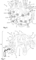
- FIG 1 illustrates schematically steps that are necessary for accurately determining the position of a source of an electroencephalography (EEG) signal inside the brain of a patient using a high-density EEG recording.
- EEG signals are recorded by multiple recording electrodes which are manually glued onto the head of the patient in high spatial density, which is a rather tedious and unpleasant procedure.
- each electrode position will vary such that it needs to be first determined, even if the spacing between the electrodes is equidistant.
- the determination of each electrode position relative to the patient's skull is achieved (in the state-of-the-art) by optically scanning the head of the patient, thereby locating each electrode on the head of the patient in space.
- FIG 2 presents an approach according to the invention for a highly accurate ESI using a 3D-printed electrode helmet 1 carrying a set of EEG-recording electrodes 2.
- a helmet 1 is illustrated in Figure 6 .
- the electrodes 2, which are designed as brush electrodes 9, are accurately held in place relatively to the skull of the patient wearing the helmet 1 by respective electrode holders 4.
- the electrode holders 4 are formed as integral parts of the 3D-printed shell 5,10 of the helmet 1.
- the electrodes 2 can also be used as stimulation electrodes.
- the helmet 1 may form the basis of a complex electrostimulation device 15, as shown in Figure 7 , comprising also an electronic unit 8, which may provide electrostimulation currents and/or control signals for addressing current sources 28 used in the electrostimulation and which can also record EEG signals using said electrodes 2.
- a controller 7 implemented by the electronic unit 8 can also communicate wirelessly with external devices for receiving commands and/or for transmitting measurement data.
- the holders 4 are equipped with feed channels 23 through which a conductive gel can be applied to each brush electrode 9 for further lowering the contact resistance.
- Each electrode 2 is electrically contacted either by an integrated wiring 14 or by cables attached to the respective electrode connector 12 shown in Figure 6 and 7 .
- Figure 2 allows determination of the spatial location and/or extent of at least one electrical source within the brain from the computed charge distribution, but importantly without performing any tedious 3D optical scanning of the helmet 1. This is because the position of each electrode 2 is well-known from the 3D design data of the helmet 1 and can thus be considered during said computation.
- the 3D design data used for fabricating the helmet 1 by 3D printing, including the individual electrode positions, are determined based on existing patient-specific 3D anatomical data measured from a patient's head using MRI, as illustrated in Figure 2 .
- the position of each electrode 2 is not only well-known but deliberately chosen to perform a certain task, for example accurately determining the location of an unknown source within the head of the patient by ESI or accurately stimulation a particular region of interest (ROI) that has been identified by a clinician in the MRI images.
- ROI region of interest
- stimulation electrodes 2 are often supplied with electric current by means of a current source 28, as schematically illustrated in Figure 3 .
- a current source 28 which can be modeled by respective variable resistances R Sij between single electrodes 2 Ei, as shown in Figure 3
- the electronic current control will regulate the electrical drive voltage downward to keep the electrical current I0 flowing through the stimulation electrode 2 E1 constant (current control).
- less current will reach the brain 30, because a greater part of the injected current is flowing only superficially (towards electrodes E2-E5 via the respective resistive paths modeled by resistors R Sij ) but not into the brain 30.
- this situation of electrode stimulation can be imagined as injecting current by means of a current source 28 into an electrical parallel circuit of two resistors R1 and R2, as illustrated in Figure 5 :
- the first electrical resistance R1 corresponds to the almost invariable resistance, which is formed by the current path into the brain 30.
- the second resistance R2, on the other hand, corresponds to the superficial current paths that exists between the stimulation electrode and potential current sinks (for example, a sensing electrode 2, 34, namely E2/E3/E4/E5, as shown in Figure 3 ). If a known current I0 is injected and the superficial conductivity on the scalp 31 increases such that R2 decreases, then the current flow I1 through the first resistor R1 will decrease and so will the amount of current injected into the brain 30.
- the proposed approach detailed before which consists in considering such changes of the scalp conductivity, can therefore be understood that by using an electrical measurement on the surface of the patient's skull, the resistance R2 can be determined such that, in terms of control, the current flow I0 delivered by the stimulation electrode E1 (cf. Figure 3 ) can be adjusted in such a way that the current flow I1 into the brain 30 (cf. Figure 5 ) can be kept constant and thus a constant electrostimulation can be maintained within the brain 30 during a stimulation session.
- the helmet 1, more precisely its controller 7 can perform such electrical surface conductivity measurements and correspondingly adapt the electrical stimulation current I0 delivered through one particular stimulation electrode E1, as illustrated in Figure 3 .
- the adjustment of the stimulation current I0 injected into the scalp 29 can also be carried out dynamically, for example, during a stimulation session, or at the beginning of such a session as part as a series of such stimulation sessions, by the controller 7 of the helmet 1. Thereby, variations of the electrical conductivity of the scalp 29 of the patient can be compensated for.
- the impedance measurement can be designed in such a way that the electrostimulation is interrupted, in case a control (in particular impedance) measurement, performed intermediately with the at least one source electrode 2, 33 E1 and the at least one sensing electrode 2, 34 (E2, E3, E4, E5 in Figure 3 ), has revealed that the impedance has decreased too much (e.g. below a threshold value) or the conductivity has increased too much (e.g. above a threshold value).
- a four-probe-measurement-scheme (sometimes called "four-probe-method") can be used to measure the conductivity of the scalp 29 of the patient using the electrode helmet 1, as illustrated in Figure 4 :
- four of the electrodes 2 of the helmet 1, which are arranged more or less in a straight line, may be employed for such a measurement by placing them at equal spacings s from each other, as shown in Figure 4 .
- the two outer of the four electrodes 2 E1 and E4 then serve to deliver a measurement current I m to the scalp 29 while with the inner two electrodes 2 E2 and E3, a voltage drop ⁇ V resulting from the measurement current I m can be measured.
- the slope of the so-obtained ⁇ V/I-curve provides the impedance of the scalp 29, which is modeled as a thin film, similar to 4-point-probe measurements conducted in the semiconductor industry.
- the sheet resistance is generally measured using the units ⁇ / ⁇ (ohms per square), to differentiate it from bulk resistance. The above equation is only valid if the material being tested is no thicker than 40% of the spacing s between the probes and if the lateral size of the sample is sufficiently large. Both factors can be fulfilled by a suitable electrode arrangement on the helmet 1.
- the approach presented here can result in a method for a dynamic adaptation of an electrical stimulation current I0 as applied in an electrostimulation in dependence of an electrical impedance measurement (in particular performed as a four-probe-measurement as laid out above), wherein the electrical impedance measurement has been or is carried out with the aid of a source electrode 2, 33 (E1 in Figure 3 ) and at least one, preferably several, sensing electrodes 2, 34 (E2, E3, E4 and E5 in Figure 3 ). All of these electrodes 2, 34 may be carried by a helmet 1 as described herein.
- ESI electroencephalography source imaging
- the approach is based on an electrode helmet 1 that carries a set of electrodes 2 at precisely known and predefined spatial positions, in particular because each electrode 2 is held in place by a respective electrode holder 4 of the helmet 1.
- the helmet 1 in particular said electrode holders 4, can be 3D-printed based on 3D design data which are based on patient-specific 3D anatomical data, the helmet 1 offers a platform for patient-specific recording of EEG signals and/or electrostimulation. Accordingly, tedious 3D optical scanning of each electrode 2 position is no longer necessary, such that highly accurate ESI and electrostimulation are possible as soon as the patient is wearing the helmet 1 in the intended well-defined orientation on his head (cf. Figure 2 ).
Landscapes
- Health & Medical Sciences (AREA)
- Life Sciences & Earth Sciences (AREA)
- Animal Behavior & Ethology (AREA)
- Veterinary Medicine (AREA)
- Public Health (AREA)
- Engineering & Computer Science (AREA)
- Biomedical Technology (AREA)
- General Health & Medical Sciences (AREA)
- Surgery (AREA)
- Molecular Biology (AREA)
- Physics & Mathematics (AREA)
- Medical Informatics (AREA)
- Heart & Thoracic Surgery (AREA)
- Pathology (AREA)
- Biophysics (AREA)
- Nuclear Medicine, Radiotherapy & Molecular Imaging (AREA)
- Radiology & Medical Imaging (AREA)
- Psychiatry (AREA)
- Psychology (AREA)
- Magnetic Resonance Imaging Apparatus (AREA)
Priority Applications (1)
| Application Number | Priority Date | Filing Date | Title |
|---|---|---|---|
| EP23207519.2A EP4548847A1 (de) | 2023-11-02 | 2023-11-02 | Verfahren und vorrichtungen für verbesserte eeg-quellenbildgebung und verbesserte elektrostimulation des gehirns |
Applications Claiming Priority (1)
| Application Number | Priority Date | Filing Date | Title |
|---|---|---|---|
| EP23207519.2A EP4548847A1 (de) | 2023-11-02 | 2023-11-02 | Verfahren und vorrichtungen für verbesserte eeg-quellenbildgebung und verbesserte elektrostimulation des gehirns |
Publications (1)
| Publication Number | Publication Date |
|---|---|
| EP4548847A1 true EP4548847A1 (de) | 2025-05-07 |
Family
ID=88690036
Family Applications (1)
| Application Number | Title | Priority Date | Filing Date |
|---|---|---|---|
| EP23207519.2A Pending EP4548847A1 (de) | 2023-11-02 | 2023-11-02 | Verfahren und vorrichtungen für verbesserte eeg-quellenbildgebung und verbesserte elektrostimulation des gehirns |
Country Status (1)
| Country | Link |
|---|---|
| EP (1) | EP4548847A1 (de) |
Citations (6)
| Publication number | Priority date | Publication date | Assignee | Title |
|---|---|---|---|---|
| US20120265261A1 (en) * | 2009-04-13 | 2012-10-18 | Marom Bikson | Neurocranial Electrostimulation Models, Systems, Devices, and Methods |
| US20180310854A1 (en) * | 2015-11-01 | 2018-11-01 | Elminda Ltd. | Method and system for estimating potential distribution on cortical surface |
| US20210015427A1 (en) | 2019-07-20 | 2021-01-21 | QuSpin Inc. | Easily customizable multi-shell meg helmet |
| US10946196B2 (en) * | 2012-11-16 | 2021-03-16 | Stimscience Inc. | System for variably configurable, adaptable electrode arrays and effectuating software |
| WO2023001546A1 (en) * | 2021-07-19 | 2023-01-26 | Bottneuro Ag | Computer-implemented method for enabling patient-specific electrostimulation of neuronal tissue and associated devices and software |
| US20230270369A1 (en) * | 2020-05-29 | 2023-08-31 | Hans L. Trinkaus | Technical device and method for generating, detecting, and identifying characteristic patterns in physiological and pathological data |
-
2023
- 2023-11-02 EP EP23207519.2A patent/EP4548847A1/de active Pending
Patent Citations (6)
| Publication number | Priority date | Publication date | Assignee | Title |
|---|---|---|---|---|
| US20120265261A1 (en) * | 2009-04-13 | 2012-10-18 | Marom Bikson | Neurocranial Electrostimulation Models, Systems, Devices, and Methods |
| US10946196B2 (en) * | 2012-11-16 | 2021-03-16 | Stimscience Inc. | System for variably configurable, adaptable electrode arrays and effectuating software |
| US20180310854A1 (en) * | 2015-11-01 | 2018-11-01 | Elminda Ltd. | Method and system for estimating potential distribution on cortical surface |
| US20210015427A1 (en) | 2019-07-20 | 2021-01-21 | QuSpin Inc. | Easily customizable multi-shell meg helmet |
| US20230270369A1 (en) * | 2020-05-29 | 2023-08-31 | Hans L. Trinkaus | Technical device and method for generating, detecting, and identifying characteristic patterns in physiological and pathological data |
| WO2023001546A1 (en) * | 2021-07-19 | 2023-01-26 | Bottneuro Ag | Computer-implemented method for enabling patient-specific electrostimulation of neuronal tissue and associated devices and software |
Non-Patent Citations (1)
| Title |
|---|
| WANG HE ET AL: "Individualized and clinically friendly helmet-type coil positioning method (I-Helmet) for transcranial magnetic stimulation", BRAIN STIMULATION, ELSEVIER, AMSTERDAM, NL, vol. 15, no. 5, 31 July 2022 (2022-07-31), pages 1023 - 1025, XP087198080, ISSN: 1935-861X, [retrieved on 20220731], DOI: 10.1016/J.BRS.2022.07.045 * |
Similar Documents
| Publication | Publication Date | Title |
|---|---|---|
| Lemieux et al. | Comparison of spike-triggered functional MRI BOLD activation and EEG dipole model localization | |
| US6594521B2 (en) | Method for localizing electrical activity in the body | |
| Fernández-Corazza et al. | Skull modeling effects in conductivity estimates using parametric electrical impedance tomography | |
| US9307925B2 (en) | Methods and systems for generating electrical property maps of biological structures | |
| US10065034B2 (en) | Method and system for controlling neural activity in the brain | |
| US20090099623A1 (en) | Systems and methods for treatment of medical conditions related to the central nervous system and for enhancing cognitive functions | |
| US20180345006A1 (en) | Electrode apparatus | |
| US9173588B2 (en) | Method for identifying stimulation target | |
| US20030078485A1 (en) | Navigated microprobe | |
| US20070043268A1 (en) | Guided Electrical Transcranial Stimulation (GETS) Technique | |
| EP4284489B1 (de) | Impedanztomografie mit elektroden eines tumorbehandlungsfeldsystems | |
| US10905882B2 (en) | Systems and methods for predicting optimal deep brain stimulation parameters | |
| WO2009044271A2 (en) | Systems and methods for treatment of medical conditions related to the central nervous system and for enhancing cognitive functions | |
| Lascano et al. | Surgically relevant localization of the central sulcus with high-density somatosensory-evoked potentials compared with functional magnetic resonance imaging | |
| EP3666183B1 (de) | Bioimpedanzmessverfahren und vorrichtung mit elektrischer stimulation | |
| CN119156242A (zh) | 医疗调控系统及其使用方法和可读存储介质 | |
| EP4548847A1 (de) | Verfahren und vorrichtungen für verbesserte eeg-quellenbildgebung und verbesserte elektrostimulation des gehirns | |
| Karhu et al. | Navigated transcranial magnetic stimulation: principles and protocol for mapping the motor cortex | |
| Kuratko et al. | Forward model of rat electroencephalogram: comparative study of numerical simulations with measurements on rat head phantoms | |
| US11273310B2 (en) | Systems and methods for predicting optimal deep brain stimulation parameters | |
| Cubo et al. | Online tissue conductivity estimation in deep brain stimulation | |
| Allard et al. | MRI guided transcranial acoustoelectric imaging for safe and accurate electrical brain mapping | |
| CN117898677B (zh) | 一种基于脑磁图和功能磁共振成像的听觉神经表征装置 | |
| Holder | EIT Imaging of Brain and Nerves | |
| Yuan et al. | A Noninvasive Focused Ultrasound-Evoked Electrophysiological Mapping Method with High Spatiotemporal Precision |
Legal Events
| Date | Code | Title | Description |
|---|---|---|---|
| PUAI | Public reference made under article 153(3) epc to a published international application that has entered the european phase |
Free format text: ORIGINAL CODE: 0009012 |
|
| STAA | Information on the status of an ep patent application or granted ep patent |
Free format text: STATUS: REQUEST FOR EXAMINATION WAS MADE |
|
| 17P | Request for examination filed |
Effective date: 20241220 |
|
| AK | Designated contracting states |
Kind code of ref document: A1 Designated state(s): AL AT BE BG CH CY CZ DE DK EE ES FI FR GB GR HR HU IE IS IT LI LT LU LV MC ME MK MT NL NO PL PT RO RS SE SI SK SM TR |
|
| STAA | Information on the status of an ep patent application or granted ep patent |
Free format text: STATUS: EXAMINATION IS IN PROGRESS |
|
| 17Q | First examination report despatched |
Effective date: 20250910 |