EP4546638A1 - Determining an initial angular position of a rotor of a salient-pole permanent magnet electrical machine - Google Patents
Determining an initial angular position of a rotor of a salient-pole permanent magnet electrical machine Download PDFInfo
- Publication number
- EP4546638A1 EP4546638A1 EP23205829.7A EP23205829A EP4546638A1 EP 4546638 A1 EP4546638 A1 EP 4546638A1 EP 23205829 A EP23205829 A EP 23205829A EP 4546638 A1 EP4546638 A1 EP 4546638A1
- Authority
- EP
- European Patent Office
- Prior art keywords
- axis
- permanent magnet
- angle
- signal injection
- electrical machine
- Prior art date
- Legal status (The legal status is an assumption and is not a legal conclusion. Google has not performed a legal analysis and makes no representation as to the accuracy of the status listed.)
- Pending
Links
Images



Classifications
-
- H—ELECTRICITY
- H02—GENERATION; CONVERSION OR DISTRIBUTION OF ELECTRIC POWER
- H02P—CONTROL OR REGULATION OF ELECTRIC MOTORS, ELECTRIC GENERATORS OR DYNAMO-ELECTRIC CONVERTERS; CONTROLLING TRANSFORMERS, REACTORS OR CHOKE COILS
- H02P6/00—Arrangements for controlling synchronous motors or other dynamo-electric motors using electronic commutation dependent on the rotor position; Electronic commutators therefor
- H02P6/14—Electronic commutators
- H02P6/16—Circuit arrangements for detecting position
- H02P6/18—Circuit arrangements for detecting position without separate position detecting elements
- H02P6/185—Circuit arrangements for detecting position without separate position detecting elements using inductance sensing, e.g. pulse excitation
-
- H—ELECTRICITY
- H02—GENERATION; CONVERSION OR DISTRIBUTION OF ELECTRIC POWER
- H02P—CONTROL OR REGULATION OF ELECTRIC MOTORS, ELECTRIC GENERATORS OR DYNAMO-ELECTRIC CONVERTERS; CONTROLLING TRANSFORMERS, REACTORS OR CHOKE COILS
- H02P21/00—Arrangements or methods for the control of electric machines by vector control, e.g. by control of field orientation
- H02P21/24—Vector control not involving the use of rotor position or rotor speed sensors
- H02P21/32—Determining the initial rotor position
-
- H—ELECTRICITY
- H02—GENERATION; CONVERSION OR DISTRIBUTION OF ELECTRIC POWER
- H02P—CONTROL OR REGULATION OF ELECTRIC MOTORS, ELECTRIC GENERATORS OR DYNAMO-ELECTRIC CONVERTERS; CONTROLLING TRANSFORMERS, REACTORS OR CHOKE COILS
- H02P21/00—Arrangements or methods for the control of electric machines by vector control, e.g. by control of field orientation
- H02P21/14—Estimation or adaptation of machine parameters, e.g. flux, current or voltage
- H02P21/18—Estimation of position or speed
-
- H—ELECTRICITY
- H02—GENERATION; CONVERSION OR DISTRIBUTION OF ELECTRIC POWER
- H02P—CONTROL OR REGULATION OF ELECTRIC MOTORS, ELECTRIC GENERATORS OR DYNAMO-ELECTRIC CONVERTERS; CONTROLLING TRANSFORMERS, REACTORS OR CHOKE COILS
- H02P25/00—Arrangements or methods for the control of AC motors characterised by the kind of AC motor or by structural details
- H02P25/02—Arrangements or methods for the control of AC motors characterised by the kind of AC motor or by structural details characterised by the kind of motor
- H02P25/022—Synchronous motors
- H02P25/024—Synchronous motors controlled by supply frequency
- H02P25/026—Synchronous motors controlled by supply frequency thereby detecting the rotor position
-
- H—ELECTRICITY
- H02—GENERATION; CONVERSION OR DISTRIBUTION OF ELECTRIC POWER
- H02P—CONTROL OR REGULATION OF ELECTRIC MOTORS, ELECTRIC GENERATORS OR DYNAMO-ELECTRIC CONVERTERS; CONTROLLING TRANSFORMERS, REACTORS OR CHOKE COILS
- H02P27/00—Arrangements or methods for the control of AC motors characterised by the kind of supply voltage
- H02P27/04—Arrangements or methods for the control of AC motors characterised by the kind of supply voltage using variable-frequency supply voltage, e.g. inverter or converter supply voltage
- H02P27/06—Arrangements or methods for the control of AC motors characterised by the kind of supply voltage using variable-frequency supply voltage, e.g. inverter or converter supply voltage using DC to AC converters or inverters
- H02P27/08—Arrangements or methods for the control of AC motors characterised by the kind of supply voltage using variable-frequency supply voltage, e.g. inverter or converter supply voltage using DC to AC converters or inverters with pulse width modulation
- H02P27/12—Arrangements or methods for the control of AC motors characterised by the kind of supply voltage using variable-frequency supply voltage, e.g. inverter or converter supply voltage using DC to AC converters or inverters with pulse width modulation pulsing by guiding the flux vector, current vector or voltage vector on a circle or a closed curve, e.g. for direct torque control
-
- H—ELECTRICITY
- H02—GENERATION; CONVERSION OR DISTRIBUTION OF ELECTRIC POWER
- H02P—CONTROL OR REGULATION OF ELECTRIC MOTORS, ELECTRIC GENERATORS OR DYNAMO-ELECTRIC CONVERTERS; CONTROLLING TRANSFORMERS, REACTORS OR CHOKE COILS
- H02P2203/00—Indexing scheme relating to controlling arrangements characterised by the means for detecting the position of the rotor
- H02P2203/03—Determination of the rotor position, e.g. initial rotor position, during standstill or low speed operation
-
- H—ELECTRICITY
- H02—GENERATION; CONVERSION OR DISTRIBUTION OF ELECTRIC POWER
- H02P—CONTROL OR REGULATION OF ELECTRIC MOTORS, ELECTRIC GENERATORS OR DYNAMO-ELECTRIC CONVERTERS; CONTROLLING TRANSFORMERS, REACTORS OR CHOKE COILS
- H02P2203/00—Indexing scheme relating to controlling arrangements characterised by the means for detecting the position of the rotor
- H02P2203/11—Determination or estimation of the rotor position or other motor parameters based on the analysis of high-frequency signals
-
- H—ELECTRICITY
- H02—GENERATION; CONVERSION OR DISTRIBUTION OF ELECTRIC POWER
- H02P—CONTROL OR REGULATION OF ELECTRIC MOTORS, ELECTRIC GENERATORS OR DYNAMO-ELECTRIC CONVERTERS; CONTROLLING TRANSFORMERS, REACTORS OR CHOKE COILS
- H02P2207/00—Indexing scheme relating to controlling arrangements characterised by the type of motor
- H02P2207/05—Synchronous machines, e.g. with permanent magnets or DC excitation
-
- H—ELECTRICITY
- H02—GENERATION; CONVERSION OR DISTRIBUTION OF ELECTRIC POWER
- H02P—CONTROL OR REGULATION OF ELECTRIC MOTORS, ELECTRIC GENERATORS OR DYNAMO-ELECTRIC CONVERTERS; CONTROLLING TRANSFORMERS, REACTORS OR CHOKE COILS
- H02P27/00—Arrangements or methods for the control of AC motors characterised by the kind of supply voltage
- H02P27/04—Arrangements or methods for the control of AC motors characterised by the kind of supply voltage using variable-frequency supply voltage, e.g. inverter or converter supply voltage
- H02P27/06—Arrangements or methods for the control of AC motors characterised by the kind of supply voltage using variable-frequency supply voltage, e.g. inverter or converter supply voltage using DC to AC converters or inverters
Definitions
- the present invention relates to the field of electrical machines and methods and arrangements for controlling electrical machines, and more particularly to determining an initial angular position of a rotor of a salient-pole permanent magnet electrical machine.
- Permanent magnet electrical machines such as permanent magnet assisted synchronous machines and salient pole permanent magnet synchronous motors, are used for a plurality of applications.
- Rotating electrical machines are typically controlled using a frequency converter, and for the controlled operation information regarding electrical behaviour of the machine is required. Such information is fed to the controller of the frequency converter in form of electrical parameters of the machine.
- an accurate initial rotor position is required as initial state for adjusting the direct-quadrature (dq) coordinate system, torque, and flux/voltage estimation etc.
- dq direct-quadrature
- AC injection methods also exist in the literature, such as e.g. a voltage pulse signal injection method, a sinusoidal high-frequency (HF) signal injection method and a high-frequency (HF) square-wave signal injection method.
- HF high-frequency
- these methods can give 180 degrees error due to the polarity of the permanent magnet flux.
- these methods usually use the saturation behavior of the motor to find the polarity of the permanent magnet flux.
- Figure 1A illustrates one example of an angular position of a rotor of a permanent magnet electrical machine before a direct current injection in a rotor angular position estimation method according to the prior art.
- DC injection direction is 0 degrees
- DC,dir 0°
- the initial electrical position of the shaft is 36 degrees
- ⁇ PM 36°.
- Figure 1B illustrates one example of an angular position of a rotor of a permanent magnet electrical machine after a direct current injection in a rotor angular position estimation method according to the prior art.
- an angular position of a rotor of a permanent magnet electrical machine after the direct current injection i.e., the electrical position of the shaft is 74 degrees
- ⁇ PM 74°.
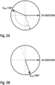
- Figure 2A illustrates another example of an angular position of a rotor of a permanent magnet electrical machine before a direct current injection in a rotor angular position estimation method according to the prior art.
- Figure 3A illustrates a third example of an angular position of a rotor of a permanent magnet electrical machine before a direct current injection in a rotor angular position estimation method according to the prior art.
- ⁇ PM 180°.
- the direct current injection is performed, this will not move the angular position of the rotor, i.e. magnetic flux remain at 180 degrees.
- Figure 3B illustrates a third example of an angular position of a rotor of a permanent magnet electrical machine after a direct current injection in a rotor angular position estimation method according to the prior art.
- the object of the invention is to introduce a method for determining an initial angular position of a rotor of a salient-pole permanent magnet electrical machine, which would be more effective than the current prior art solutions.
- Advantageous embodiments are furthermore presented.
- a first signal injection step is performed, in which first signal injection step an initial angle of the permanent magnet flux axis ⁇ d,axis, 1 is determined;
- a second signal injection step is performed, in which second signal injection step an angle of the permanent magnet flux axis ⁇ d,axis, 2 is determined; and the initial angular position ⁇ init of a rotor of a salient-pole permanent magnet electrical machine connected to a frequency converter, in which method: a first signal injection step is performed, in which first signal injection step an initial angle of the permanent magnet flux axis
- a first pulse test is performed, in which first pulse test number of external pulses are injected into an idle salient-pole permanent magnet electrical machine at selected angles, the ratio of the current to the flux is measured for each injected pulse, and the initial angle of the permanent magnet flux axis ⁇ d,axis, 1 is determined by performing a discrete Fourier transform (DFT, discrete Fourier transform) on the measured ratios; and in said second signal injection step a second pulse test is performed, in which second pulse test number of external pulses are injected into an idle salient-pole permanent magnet electrical machine at selected angles, the ratio of the current to the flux is measured for each injected pulse, and the angle of the permanent magnet flux axis ⁇ d,axis, 2 is determined by performing a discrete Fourier transform (DFT, discrete Fourier transform) on the measured ratios.
- DFT discrete Fourier transform
- said initial angle of the permanent magnet flux axis ⁇ d,axis, 1 is determined by utilizing AC injection and/or wherein in said second signal injection step said angle of the permanent magnet flux axis ⁇ d,axis, 2 is determined by utilizing AC injection.
- said initial angle of the permanent magnet flux axis ⁇ d,axis, 1 is determined by utilizing voltage pulses signal injection and/or wherein in said second signal injection step said angle of the permanent magnet flux axis ⁇ d,axis, 2 is determined by utilizing voltage pulses signal injection.
- said initial angle of the permanent magnet flux axis ⁇ d,axis, 1 is determined by utilizing sinusoidal high-frequency (HF) signal injection or high-frequency (HF) square wave signal injection and/or wherein in said second signal injection step said angle of the permanent magnet flux axis ⁇ d,axis, 2 is determined by utilizing sinusoidal high-frequency (HF) signal injection or high-frequency (HF) square wave signal injection.
- HF high-frequency
- HF high-frequency
- said added angle ⁇ add is 90 degrees.
- said added angle ⁇ add is between 50 - 130 degrees.
- said added angle ⁇ add is between 30 - 150 degrees.
- said first pulse test and/or said second pulse test is/are performed as a six-pulse test, in which six-pulse test the ratio of the current to the flux is measured with the pulses at angles of 0, 60, 120, 180, 240 and 300 degrees.
- six voltage pulses are produced in an order that minimizes the possibility of rotating the rotor of the salient-pole permanent magnet electrical machine.
- a new frequency converter adapted to be connected to a salient-pole permanent magnet electrical machine
- said frequency converter in performing said first signal injection step said frequency converter comprises means configured to perform a first pulse test, in which first pulse test number of external pulses are injected into an idle salient-pole permanent magnet electrical machine at selected angles, the ratio of the current to the flux is measured for each injected pulse, and the initial angle of the permanent magnet flux axis ⁇ d,axis, 1 is determined by performing a discrete Fourier transform (DFT, discrete Fourier transform) on the measured ratios; and in performing said second signal injection step said frequency converter comprises means configured to perform a second pulse test, in which second pulse test number of external pulses are injected into an idle salient-pole permanent magnet electrical machine at selected angles, the ratio of the current to the flux is measured for each injected pulse, and the angle of the permanent magnet flux axis ⁇ d,axis, 2 is determined by performing a discrete Fourier transform (DFT, discrete Fourier transform) on the measured ratios.
- DFT discrete Fourier transform
- said frequency converter in performing said first signal injection step said frequency converter comprises means configured to determine said initial angle of the permanent magnet flux axis ⁇ d,axis, 1 utilizing AC injection, voltage pulses signal injection, sinusoidal high-frequency (HF) signal injection or high-frequency (HF) square wave signal injection and/or wherein in performing said second signal injection step said frequency converter comprises means configured to determine said angle of the permanent magnet flux axis ⁇ d,axis, 2 utilizing AC injection, voltage pulses signal injection, sinusoidal high-frequency (HF) signal injection or high-frequency (HF) square wave signal injection.
- said first pulse test and/or said second pulse test is/are performed as a six-pulse test, in which six-pulse test the ratio of the current to the flux is measured with the pulses at angles of 0, 60, 120, 180, 240 and 300 degrees.
- a first signal injection step is performed, in which first signal injection step an initial angle of the permanent magnet flux axis ⁇ d,axis, 1 is determined;
- a second signal injection step is performed, in which second signal injection step an angle of the permanent magnet flux axis after the DC injection ⁇ d,axis, 2 is determined; and the initial angular position ⁇ init of a rotor of a salient-pole permanent magnet electrical machine connected to a frequency converter;
- an external pulse i.e., external flux
- ⁇ is the angle of the external pulse
- ⁇ d,axis is an angle of the permanent magnet flux axis.
- the angle of the permanent magnet flux axis ⁇ d,axis is the angle of d-axis i.e., the electrical angular position of the rotor in stator reference frame.
- the initial angle of the permanent magnet flux axis ⁇ d,axis, 1 is the initial angle of d-axis ⁇ d,axis, 1 i.e., the initial electrical angular position of the rotor in stator reference frame.
- the voltage pulses are produced at selected angles, and with each pulse the current is measured, and the permanent magnet flux is estimated. Thereafter, the ratios of the current to the flux are calculated with the pulses at selected angles. Thereafter, the inductance values L d , L q and the initial angle of d-axis ⁇ d,axis, 1 are determined by performing a discrete Fourier transform (DFT, discrete Fourier transform) on the measured ratios.
- DFT discrete Fourier transform
- the first pulse test 11 is carried out as a six-pulse test.
- said six-pulse test the ratio of the current to the flux is measured with the pulses at angles of 0, 60, 120, 180, 240 and 300 degrees, the inductance values L d , L q and the initial angle of d-axis ⁇ d,axis, 1 are determined by performing a discrete Fourier transform (DFT, discrete Fourier transform) on the measured ratios.
- DFT discrete Fourier transform
- An example of performing a six pulse test is further explained in a European Patent specification EP 3 220 535 B1 .
- Said initial angle of d-axis ⁇ d,axis, 1 is determined as wrapped around 0° and 360°, i.e. 0° ⁇ ⁇ d,axis, 1 ⁇ 360°.
- a direct current injection 12 is performed to move and park the shaft into a new position (DC, direct current).
- DC injection direction ⁇ DC,dir is the angle of injected direct current and added angle ⁇ add is an angle defining the shift from the initial angle of the permanent magnet flux.
- Said DC injection direction ⁇ DC,dir is determined as wrapped around 0° and 360°, i.e. 0° ⁇ ⁇ DC,dir ⁇ 360°.
- the added angle ⁇ add is between 30 - 150 degrees. In another embodiment, the added angle ⁇ add is between 50 - 130 degrees. In yet another embodiment, the added angle ⁇ add is 90 degrees.
- a second signal injection 13 is performed.
- said second signal injection 13 is performed as a second pulse test 13.
- an external pulse i.e., external flux
- the angle of the permanent magnet flux axis ⁇ d,axis, 2 is found.
- Said angle of the permanent magnet flux axis ⁇ d,axis, 2 is determined as wrapped around 0° and 360°, i.e. 0° ⁇ ⁇ d,axis, 2 ⁇ 360°.
- the angle of the permanent magnet flux axis ⁇ d,axis, 2 is the angle of d-axis after the DC injection ⁇ d,axis, 2 i.e., the electrical angular position of the rotor in stator reference frame after the DC injection.
- the voltage pulses are produced at selected angles, and with each pulse the current is measured, and the permanent magnet flux is estimated. Thereafter, the ratios of the current to the flux are calculated with the pulses at selected angles. Thereafter, the inductance values L d , L q and the angle of d-axis after the DC injection ⁇ d,axis, 2 are determined by performing a discrete Fourier transform (DFT, discrete Fourier transform) on the measured ratios.
- DFT discrete Fourier transform
- the second pulse test is carried out as a six-pulse test.
- said six-pulse test the ratio of the current to the flux is measured with the pulses at angles of 0, 60, 120, 180, 240 and 300 degrees, the inductance values L d , L q and the angle of d-axis after the DC injection ⁇ d,axis, 2 are determined by performing a discrete Fourier transform (DFT, discrete Fourier transform) on the measured ratios.
- DFT discrete Fourier transform
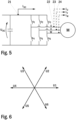
- Figure 5 illustrates a simplified structure of an embodiment of an inverter of a frequency converter according to the present invention.
- Figure 5 shows a three-phase inverter of a frequency converter and the load connected to the output phases.
- the presented frequency converter is equipped with a current measurement sensor 21 in the intermediate voltage circuit. With the help of the present invention the use of a two-phase current measurement sensor or of a three-phase current measurement sensor is not required.
- the presented frequency converter may comprise a two-phase current measurement sensor or a three-phase current measurement sensor in the intermediate voltage circuit output instead of or in addition to said current measurement sensor 21 in the intermediate voltage circuit.
- the presented frequency converter may have three-phase current measurement sensors 22-24 in the three-phase output as indicated by dashed lines and reference numbers 22-24.
- voltage pulses are produced or generated with the frequency converter to the salient-pole permanent magnet electrical machine.
- the voltage pulses are produced by selecting suitable switch combinations using the output switches s1-s6 of the frequency converter.
- the voltage pulses are produced to each output phase of the frequency converter and thus to each phase of the connected machine. For example, by closing switches s1, s5 and s6 a voltage pulse is generated to output phase U and the magnitude of the voltage pulse is the voltage of the intermediate voltage circuit Udc. With the six output switches six different active combinations of the switch states is obtained.
- Figure 6 illustrates voltage vectors obtained with the inverter of Figure 5 .
- the switch combinations are presented as voltage vectors in which the above mentioned switch combination (s1, s5 and s6 closed) corresponds to vector U1.
- voltage pulses are produced to each phase of the machine. This means that voltage vectors U1 to U6 are generated. As six voltage pulses are produced, these include a positive and a negative pulse for each phase.
- the pulses are preferably produced in an order that minimizes the possibility of rotating the rotor of the machine.
- such an order is, for example, U1, U4, U2, U5, U3, U6.
- the consecutive voltage vectors are selected to be in as opposite direction as possible so that the produced voltages are not able to produce a rotating magnetic flux in the machine which could rotate the rotor of the machine.
- the average torque at the end of the produced pulses is zero. This minimizes the shaft movements.
- Figure 7B illustrates an embodiment of an angular position of a rotor of a salient-pole permanent magnet electrical machine before and after a direct current injection according to the present invention.
- the direct current injection is performed, this will move the shaft and move the magnetic flux from 72 degrees to 81 degrees.
- the second signal injection step is performed for finding out the angle of the permanent magnet flux axis ⁇ d,axis, 2 .
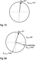
- Figure 7C illustrates an embodiment of an angular position of a rotor of a salient-pole permanent magnet electrical machine after a second signal injection according to the present invention.
- the added angle ⁇ add is an angle defining the shift from the initial angle of the permanent magnet flux axis ⁇ d,axis, 1 .
- the added angle ⁇ add is 90 degrees.
- the DC injection direction ⁇ DC,dir is 342 degrees
- ⁇ DC,dir 342°.
- Figure 8B illustrates another embodiment of an angular position of a rotor of a salient-pole permanent magnet electrical machine before and after a direct current injection according to the present invention.
- the direct current injection is performed, this will move the shaft and move the magnetic flux from 72 degrees to 62 degrees.
- the second signal injection step is performed for finding out the angle of the permanent magnet flux axis ⁇ d,axis, 2 .
- Figure 8C illustrates another embodiment of an angular position of a rotor of a salient-pole permanent magnet electrical machine after a second signal injection according to the present invention.
- a two-phase current measurement sensor or a three-phase current measurement sensor for measuring the current in the direction of the pulse is not needed.
- a single DC link current sensor is sufficient to measure the current in the direction of the pulse.
- the solution according to the present invention provides an effective and elegant solution for determining an initial angular position of a rotor of a salient-pole permanent magnet electrical machine.
- a single DC link current sensor is sufficient to measure the current in the direction of the pulse.
- the presented solution is more effective compared to the prior solutions and also eliminates the need for phase current measurements so that the use of a two-phase current measurement sensor or of a three-phase current measurement sensor is not required.
- the invention can be implemented in existing frequency converters.
- Present frequency converters comprise processors and memory that can be utilized in the functions according to embodiments of the invention.
- all modifications and configurations required for implementing an embodiment of the invention may be performed as software routines, which may be implemented as added or updated software routines.
- software can be provided as a computer program product comprising computer program code which, when run on a computer, causes the computer or corresponding arrangement to perform the functionality according to the invention as described above.
- Such a computer program code may be stored or generally embodied on a computer readable medium, such as suitable memory, e.g. a flash memory or a disc memory from which it is loadable to the unit or units executing the program code.
- a computer program code implementing the invention may be loaded to the unit or units executing the computer program code via a suitable data network, for example, and it may replace or update a possibly existing program code.
Landscapes
- Engineering & Computer Science (AREA)
- Power Engineering (AREA)
- Control Of Motors That Do Not Use Commutators (AREA)
- Control Of Ac Motors In General (AREA)
Abstract
The present invention relates to the field of electrical machines and methods and arrangements for controlling electrical machines, and more particularly to determining an initial angular position of a rotor of a salient-pole permanent magnet electrical machine. The method for determining an initial angular position of a rotor of a salient-pole permanent magnet electrical machine connected to a frequency converter comprises: performing a first signal injection step, in which first signal injection step an initial angle of the permanent magnet flux axis θ d,axis,1 is determined; performing a DC injection (12) is performed, in which a direct current is injected into an idle permanent magnet electrical machine to a DC injection direction; performing a second signal injection step, in which second signal injection step an angle of the permanent magnet flux axis θ d,axis,2 is determined; and determining (16) the initial angular position of a rotor of a permanent magnet electrical machine.
Description
- The present invention relates to the field of electrical machines and methods and arrangements for controlling electrical machines, and more particularly to determining an initial angular position of a rotor of a salient-pole permanent magnet electrical machine.
- Permanent magnet electrical machines, such as permanent magnet assisted synchronous machines and salient pole permanent magnet synchronous motors, are used for a plurality of applications.
- Rotating electrical machines are typically controlled using a frequency converter, and for the controlled operation information regarding electrical behaviour of the machine is required. Such information is fed to the controller of the frequency converter in form of electrical parameters of the machine. For field oriented control, an accurate initial rotor position is required as initial state for adjusting the direct-quadrature (dq) coordinate system, torque, and flux/voltage estimation etc. Thus, the errors in the initial rotor position has an impact on the starting of a PMSM drive and may lead to the performance degradation.
- Initial rotor position estimation is used for determining the angular position of the magnetic flux of a permanent magnet electrical machine, such as a permanent magnet synchronous motor (PMSM). One known initial rotor position estimation method is the direct current injection method i.e., DC injection, which DC injection is used for intentionally aligning the shaft to an intended direction. In a direct current injection method as a DC current is injected, the permanent magnet flux axis, also referred to as d-axis, aligns with the current direction with the surface mounted permanent magnet (SPM) motors. As a result, after said DC injection the initial rotor position will be the same as the DC current direction.
- However, with other permanent magnet electrical machines, e.g. in case of highly salient interior permanent magnet (IPM) motors and permanent magnet assisted synchronous reluctance motors (PMaSynRM), the magnetic flux may not align with the DC current direction.
- In this type of permanent magnet electrical machines, the magnetic flux usually turns by the DC direction and settles in a position smaller than 90 degrees further from the DC direction, depending on the saliency. This is referred to as the DC parking of the rotor shaft. Therefore, it is not correct to use the DC direction as the initial position of the magnetic flux.
- Different types of AC injection methods also exist in the literature, such as e.g. a voltage pulse signal injection method, a sinusoidal high-frequency (HF) signal injection method and a high-frequency (HF) square-wave signal injection method. However, these methods can give 180 degrees error due to the polarity of the permanent magnet flux. Additionally, these methods usually use the saturation behavior of the motor to find the polarity of the permanent magnet flux.
- In the following, prior art will be described with reference to the accompanying figures, of which:
-
Figure 1A illustrates one example of an angular position of a rotor of a permanent magnet electrical machine before a direct current injection in a rotor angular position estimation method according to the prior art. -
Figure 1B illustrates one example of an angular position of a rotor of a permanent magnet electrical machine after a direct current injection in a rotor angular position estimation method according to the prior art. -
Figure 2A illustrates another example of an angular position of a rotor of a permanent magnet electrical machine before a direct current injection in a rotor angular position estimation method according to the prior art. -
Figure 2B illustrates another example of an angular position of a rotor of a permanent magnet electrical machine after a direct current injection in a rotor angular position estimation method according to the prior art. -
Figure 3A illustrates a third example of an angular position of a rotor of a permanent magnet electrical machine before a direct current injection in a rotor angular position estimation method according to the prior art. -
Figure 3B illustrates a third example of an angular position of a rotor of a permanent magnet electrical machine after a direct current injection in a rotor angular position estimation method according to the prior art. -
Figure 1A illustrates one example of an angular position of a rotor of a permanent magnet electrical machine before a direct current injection in a rotor angular position estimation method according to the prior art. InFigure 1A an example of DC parking is shown where an angular position of a rotor of a permanent magnet electrical machine before a direct current injection, where DC injection direction is 0 degrees θDC,dir = 0°, i.e., the initial electrical position of the shaft is 36 degrees θPM = 36°. As the direct current injection is performed, this will move the magnetic flux further to 74 degrees. -
Figure 1B illustrates one example of an angular position of a rotor of a permanent magnet electrical machine after a direct current injection in a rotor angular position estimation method according to the prior art. In DC parking example ofFigure 1B an angular position of a rotor of a permanent magnet electrical machine after the direct current injection i.e., the electrical position of the shaft is 74 degrees θPM = 74°. -
Figure 2A illustrates another example of an angular position of a rotor of a permanent magnet electrical machine before a direct current injection in a rotor angular position estimation method according to the prior art. InFigure 2A another example of DC parking is shown where an angular position of a rotor of a permanent magnet electrical machine before a direct current injection i.e., the initial electrical position of the shaft is 158 degrees θPM = 158°. As the direct current injection is performed, this will move the magnetic flux further to 289 degrees. -
Figure 2B illustrates another example of an angular position of a rotor of a permanent magnet electrical machine after a direct current injection in a rotor angular position estimation method according to the prior art. In another DC parking example ofFigure 2B an angular position of a rotor of a permanent magnet electrical machine after the direct current injection i.e., the electrical position of the shaft is 289 degrees θPM = 289°. -
Figure 3A illustrates a third example of an angular position of a rotor of a permanent magnet electrical machine before a direct current injection in a rotor angular position estimation method according to the prior art. InFigure 3A a third example of DC parking is shown where an angular position of a rotor of a permanent magnet electrical machine before a direct current injection i.e., the initial electrical position of the shaft is 180 degrees θPM = 180°. As the direct current injection is performed, this will not move the angular position of the rotor, i.e. magnetic flux remain at 180 degrees. -
Figure 3B illustrates a third example of an angular position of a rotor of a permanent magnet electrical machine after a direct current injection in a rotor angular position estimation method according to the prior art. In the third DC parking example ofFigure 3B an angular position of a rotor of a permanent magnet electrical machine after the direct current injection i.e., the electrical position of the shaft remains at 180 degrees θPM = 180°. - In prior art solutions for determining an initial angular position of a rotor of a salient-pole permanent magnet electrical machine, the main problems are the 180 degrees misalignment of the initial angular position of a rotor of a permanent magnet electrical machine and DC parking behavior of the rotor shaft. Also, in prior art solutions for determining an initial angular position of a rotor of a salient-pole permanent magnet electrical machine, a two-phase current measurement sensor or a three-phase current measurement sensor is needed for measuring the current in the direction of the pulse.
- In today's demanding environment, there is a need for a more effective and elegant solution for determining an initial angular position of a rotor of a salient-pole permanent magnet electrical machine, which would be more effective, and which would not require a two-phase current measurement sensor or a three-phase current measurement sensor.
- Within the technology, there is a specific need for a method for determining an initial angular position of a rotor of a salient-pole permanent magnet electrical machine that would be more effective compared to the current prior art solutions.
- The object of the invention is to introduce a method for determining an initial angular position of a rotor of a salient-pole permanent magnet electrical machine, which would be more effective than the current prior art solutions. Advantageous embodiments are furthermore presented.
- It is brought forward a new method for determining an initial angular position of a rotor of a salient-pole permanent magnet electrical machine connected to a frequency converter, in which method: a first signal injection step is performed, in which first signal injection step an initial angle of the permanent magnet flux axis θ d,axis,1 is determined; a DC injection is performed, in which DC injection a direct current is injected into an idle salient-pole permanent magnet electrical machine to a DC injection direction θDC,dir = θ d,axis,1 ± θadd , where DC injection direction θDC,dir is the angle of injected direct current and added angle θadd is an angle defining the shift from the initial angle of the permanent magnet flux axis θ d,axis,1; a second signal injection step is performed, in which second signal injection step an angle of the permanent magnet flux axis θ d,axis,2 is determined; and the initial angular position θ̂init of a rotor of a salient-pole permanent magnet electrical machine is determined as:

- In a preferred embodiment of said method, in said first signal injection step a first pulse test is performed, in which first pulse test number of external pulses are injected into an idle salient-pole permanent magnet electrical machine at selected angles, the ratio of the current to the flux is measured for each injected pulse, and the initial angle of the permanent magnet flux axis θ d,axis,1 is determined by performing a discrete Fourier transform (DFT, discrete Fourier transform) on the measured ratios; and in said second signal injection step a second pulse test is performed, in which second pulse test number of external pulses are injected into an idle salient-pole permanent magnet electrical machine at selected angles, the ratio of the current to the flux is measured for each injected pulse, and the angle of the permanent magnet flux axis θ d,axis,2 is determined by performing a discrete Fourier transform (DFT, discrete Fourier transform) on the measured ratios.
- In a preferred embodiment of said method, in said first signal injection step said initial angle of the permanent magnet flux axis θ d,axis,1 is determined by utilizing AC injection and/or wherein in said second signal injection step said angle of the permanent magnet flux axis θ d,axis,2 is determined by utilizing AC injection.
- In a preferred embodiment of said method, in said first signal injection step said initial angle of the permanent magnet flux axis θ d,axis,1 is determined by utilizing voltage pulses signal injection and/or wherein in said second signal injection step said angle of the permanent magnet flux axis θ d,axis,2 is determined by utilizing voltage pulses signal injection.
- In a preferred embodiment of said method, in said first signal injection step said initial angle of the permanent magnet flux axis θ d,axis,1 is determined by utilizing sinusoidal high-frequency (HF) signal injection or high-frequency (HF) square wave signal injection and/or wherein in said second signal injection step said angle of the permanent magnet flux axis θ d,axis,2 is determined by utilizing sinusoidal high-frequency (HF) signal injection or high-frequency (HF) square wave signal injection.
- In a preferred embodiment of said method, said added angle θadd is 90 degrees.
- In a preferred embodiment of said method, said added angle θadd is between 50 - 130 degrees.
- In a preferred embodiment of said method, said added angle θadd is between 30 - 150 degrees.
- In a preferred embodiment of said method, said first pulse test and/or said second pulse test is/are performed as a six-pulse test, in which six-pulse test the ratio of the current to the flux is measured with the pulses at angles of 0, 60, 120, 180, 240 and 300 degrees.
- In a preferred embodiment of said method, six voltage pulses are produced in an order that minimizes the possibility of rotating the rotor of the salient-pole permanent magnet electrical machine.
- Furthermore, it is brought forward a new frequency converter adapted to be connected to a salient-pole permanent magnet electrical machine, the frequency converter comprising means configured to determine an initial angular position of a rotor of a salient-pole permanent magnet electrical machine by: performing first signal injection step, in which first signal injection step an initial angle of the permanent magnet flux axis θ d,axis,1 is determined; performing a DC injection, in which DC injection a direct current is injected into an idle salient-pole permanent magnet electrical machine to a DC injection direction θDC,dir = θ d,axis,1 ± θadd , where DC injection direction θDC,dir is the angle of injected direct current and added angle θadd is an angle defining the shift from the initial angle of the permanent magnet flux axis θ d,axis,1; performing second signal injection step, in which second signal injection step an angle of the permanent magnet flux axis θ d,axis,2 is determined by; and determining the initial angular position θ̂init of a rotor of a permanent magnet electrical machine as:

- In a preferred embodiment of said frequency converter, in performing said first signal injection step said frequency converter comprises means configured to perform a first pulse test, in which first pulse test number of external pulses are injected into an idle salient-pole permanent magnet electrical machine at selected angles, the ratio of the current to the flux is measured for each injected pulse, and the initial angle of the permanent magnet flux axis θ d,axis,1 is determined by performing a discrete Fourier transform (DFT, discrete Fourier transform) on the measured ratios; and in performing said second signal injection step said frequency converter comprises means configured to perform a second pulse test, in which second pulse test number of external pulses are injected into an idle salient-pole permanent magnet electrical machine at selected angles, the ratio of the current to the flux is measured for each injected pulse, and the angle of the permanent magnet flux axis θ d,axis,2 is determined by performing a discrete Fourier transform (DFT, discrete Fourier transform) on the measured ratios.
- In a preferred embodiment of said frequency converter, in performing said first signal injection step said frequency converter comprises means configured to determine said initial angle of the permanent magnet flux axis θ d,axis,1 utilizing AC injection, voltage pulses signal injection, sinusoidal high-frequency (HF) signal injection or high-frequency (HF) square wave signal injection and/or wherein in performing said second signal injection step said frequency converter comprises means configured to determine said angle of the permanent magnet flux axis θ d,axis,2 utilizing AC injection, voltage pulses signal injection, sinusoidal high-frequency (HF) signal injection or high-frequency (HF) square wave signal injection.
- In a preferred embodiment of said first pulse test and/or said second pulse test is/are performed as a six-pulse test, in which six-pulse test the ratio of the current to the flux is measured with the pulses at angles of 0, 60, 120, 180, 240 and 300 degrees.
- Furthermore, it is brought forward a new computer program product comprising computer program code, wherein the execution of the program code in a computer causes the computer of said new frequency converter causes the computer to carry out the steps of said new method.
- In the following, the present invention will be described in more detail by way of example and with reference to the attached drawings, in which:
-
Figure 1A illustrates one example of an angular position of a rotor of a salient-pole permanent magnet electrical machine before a direct current injection in a rotor angular position estimation method according to the prior art. -
Figure 1B illustrates one example of an angular position of a rotor of a salient-pole permanent magnet electrical machine after a direct current injection in a rotor angular position estimation method according to the prior art. -
Figure 2A illustrates another example of an angular position of a rotor of a salient-pole permanent magnet electrical machine before a direct current injection in a rotor angular position estimation method according to the prior art. -
Figure 2B illustrates another example of an angular position of a rotor of a salient-pole permanent magnet electrical machine after a direct current injection in a rotor angular position estimation method according to the prior art. -
Figure 3A illustrates a third example of an angular position of a rotor of a salient-pole permanent magnet electrical machine before a direct current injection in a rotor angular position estimation method according to the prior art. -
Figure 3B illustrates a third example of an angular position of a rotor of a salient-pole permanent magnet electrical machine after a direct current injection in a rotor angular position estimation method according to the prior art. -
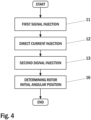
Figure 4 illustrates a flow diagram of an embodiment of a method for determining an initial angular position of a rotor of a salient-pole permanent magnet electrical machine according to the present invention. -
Figure 5 illustrates a simplified structure of an embodiment of an inverter of a frequency converter according to the present invention. -
Figure 6 illustrates voltage vectors obtained with the inverter ofFigure 5 . -
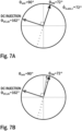
Figure 7A illustrates an embodiment of an angular position of a rotor of a salient-pole permanent magnet electrical machine after a first signal injection according to the present invention. -
Figure 7B illustrates an embodiment of an angular position of a rotor of a salient-pole permanent magnet electrical machine before and after a direct current injection according to the present invention. -
Figure 7C illustrates an embodiment of an angular position of a rotor of a salient-pole permanent magnet electrical machine after a second signal injection according to the present invention. -
Figure 8A illustrates another embodiment of an angular position of a rotor of a salient-pole permanent magnet electrical machine after a first signal injection according to the present invention. -
Figure 8B illustrates another embodiment of an angular position of a rotor of a salient-pole permanent magnet electrical machine before and after a direct current injection according to the present invention. -
Figure 8C illustrates another embodiment of an angular position of a rotor of a salient-pole permanent magnet electrical machine after a second signal injection according to the present invention. - The foregoing aspects, features and advantages of the invention will be apparent from the drawings and the detailed description related thereto.
- The prior art drawings of
Figures 1A to 3B have been presented earlier. In the following, the invention will be described in greater detail by means of preferred embodiments with reference to the accompanying drawings ofFigures 4 to 9. - In the method according to the present invention for determining an initial angular position of a rotor of a salient-pole permanent magnet electrical machine connected to a frequency converter: a first signal injection step is performed, in which first signal injection step an initial angle of the permanent magnet flux axis θ d,axis,1 is determined; a DC injection is performed, in which DC injection a direct current is injected into an idle salient-pole permanent magnet electrical machine to a DC injection direction θDC,dir = θ d,axis,1 ± θadd , where DC injection direction θDC,dir is the angle of injected direct current and added angle θadd is an angle defining the shift from the initial angle of the permanent magnet flux axis θ d,axis,1; a second signal injection step is performed, in which second signal injection step an angle of the permanent magnet flux axis after the DC injection θ d,axis,2 is determined; and the initial angular position θ̂init of a rotor of a salient-pole permanent magnet electrical machine is determined as:

-
Figure 4 illustrates a flow diagram of an embodiment of a method for determining an initial angular position of a rotor of a salient-pole permanent magnet electrical machine according to the present invention. In the presented embodiment said salient-pole permanent magnet electrical machine is connected to a frequency converter. Said frequency converter may have a current measurement with current sensor/sensors in the intermediate voltage circuit and/or in the three-phase output. In the method according to the present embodiment, afirst signal injection 11 is first performed as afirst pulse test 11. - In the
first pulse test 11 an external pulse (i.e., external flux) is injected into an idle salient-pole permanent magnet electrical machine. When the harmonics, saturation and core losses are ignored, the ratio of the current to the flux in the direction of the pulse can be expressed as
- With the help of the
first pulse test 11 the initial angle of the permanent magnet flux axis θ d,axis,1 is found. The initial angle of the permanent magnet flux axis θ d,axis,1 is the initial angle of d-axis θ d,axis,1 i.e., the initial electrical angular position of the rotor in stator reference frame. - In the
first pulse test 11 the voltage pulses are produced at selected angles, and with each pulse the current is measured, and the permanent magnet flux is estimated. Thereafter, the ratios of the current to the flux are calculated with the pulses at selected angles. Thereafter, the inductance values Ld, Lq and the initial angle of d-axis θ d,axis,1 are determined by performing a discrete Fourier transform (DFT, discrete Fourier transform) on the measured ratios. - In an embodiment, the
first pulse test 11 is carried out as a six-pulse test. In said six-pulse test the ratio of the current to the flux is measured with the pulses at angles of 0, 60, 120, 180, 240 and 300 degrees, the inductance values Ld, Lq and the initial angle of d-axis θ d,axis,1 are determined by performing a discrete Fourier transform (DFT, discrete Fourier transform) on the measured ratios. An example of performing a six pulse test is further explained in a EuropeanPatent specification EP 3 220 535 B1 . Said initial angle of d-axis θ d,axis,1 is determined as wrapped around 0° and 360°, i.e. 0° ≤ θ d,axis,1 ≤ 360°. - Here a general equation for wrapping an angle around 0° and 360° is defined as:

- After performing the
first signal injection 11 and determining the initial angle of d-axis θ d,axis,1, a directcurrent injection 12 is performed to move and park the shaft into a new position (DC, direct current). - In the direct current injection 12 a DC current of low amplitude (e.g., 0.5 times the nominal current value) is injected into an idle salient-pole permanent magnet electrical machine to a DC injection direction defined as

- In an embodiment, the added angle θadd is between 30 - 150 degrees. In another embodiment, the added angle θadd is between 50 - 130 degrees. In yet another embodiment, the added angle θadd is 90 degrees.
- It has been observed from the simulations and laboratory measurements that the direct
current injection 12 guarantees the movement of the shaft and DC parking within 90 degrees (± 90 °) from the DC direction. - After performing the direct
current injection 12, asecond signal injection 13 is performed. In the method according to the present embodiment, saidsecond signal injection 13 is performed as asecond pulse test 13. - In the
second pulse test 13 an external pulse (i.e., external flux) is injected into an idle salient-pole permanent magnet electrical machine. With the help of thesecond pulse test 13 the angle of the permanent magnet flux axis θ d,axis,2 is found. Said angle of the permanent magnet flux axis θ d,axis,2 is determined as wrapped around 0° and 360°, i.e. 0° ≤ θ d,axis,2 ≤ 360°. The angle of the permanent magnet flux axis θ d,axis,2 is the angle of d-axis after the DC injection θ d,axis,2 i.e., the electrical angular position of the rotor in stator reference frame after the DC injection. - In the
second pulse test 13 the voltage pulses are produced at selected angles, and with each pulse the current is measured, and the permanent magnet flux is estimated. Thereafter, the ratios of the current to the flux are calculated with the pulses at selected angles. Thereafter, the inductance values Ld, Lq and the angle of d-axis after the DC injection θ d,axis,2 are determined by performing a discrete Fourier transform (DFT, discrete Fourier transform) on the measured ratios. - In an embodiment, the second pulse test is carried out as a six-pulse test. In said six-pulse test the ratio of the current to the flux is measured with the pulses at angles of 0, 60, 120, 180, 240 and 300 degrees, the inductance values Ld, Lq and the angle of d-axis after the DC injection θ d,axis,2 are determined by performing a discrete Fourier transform (DFT, discrete Fourier transform) on the measured ratios.
- After performing the
second signal injection 13, the initial angular position of a rotor of a salient-pole permanent magnet electrical machine is determined 16 as:
-
Figure 5 illustrates a simplified structure of an embodiment of an inverter of a frequency converter according to the present invention.Figure 5 shows a three-phase inverter of a frequency converter and the load connected to the output phases. The presented frequency converter is equipped with acurrent measurement sensor 21 in the intermediate voltage circuit. With the help of the present invention the use of a two-phase current measurement sensor or of a three-phase current measurement sensor is not required. In an alternative solution, the presented frequency converter may comprise a two-phase current measurement sensor or a three-phase current measurement sensor in the intermediate voltage circuit output instead of or in addition to saidcurrent measurement sensor 21 in the intermediate voltage circuit. InFigure 5 , the presented frequency converter may have three-phase current measurement sensors 22-24 in the three-phase output as indicated by dashed lines and reference numbers 22-24. - In the method of the present invention voltage pulses are produced or generated with the frequency converter to the salient-pole permanent magnet electrical machine. With reference to
Figure 5 , the voltage pulses are produced by selecting suitable switch combinations using the output switches s1-s6 of the frequency converter. The voltage pulses are produced to each output phase of the frequency converter and thus to each phase of the connected machine. For example, by closing switches s1, s5 and s6 a voltage pulse is generated to output phase U and the magnitude of the voltage pulse is the voltage of the intermediate voltage circuit Udc. With the six output switches six different active combinations of the switch states is obtained. -
Figure 6 illustrates voltage vectors obtained with the inverter ofFigure 5 . InFigure 6 the switch combinations are presented as voltage vectors in which the above mentioned switch combination (s1, s5 and s6 closed) corresponds to vector U1. - In the method of the present invention voltage pulses are produced to each phase of the machine. This means that voltage vectors U1 to U6 are generated. As six voltage pulses are produced, these include a positive and a negative pulse for each phase.
- The pulses are preferably produced in an order that minimizes the possibility of rotating the rotor of the machine. Presented in vectors shown in
Figure 6 , such an order is, for example, U1, U4, U2, U5, U3, U6. The consecutive voltage vectors are selected to be in as opposite direction as possible so that the produced voltages are not able to produce a rotating magnetic flux in the machine which could rotate the rotor of the machine. In the presented embodiment ofFigure 6 the average torque at the end of the produced pulses is zero. This minimizes the shaft movements. -
Figure 7A illustrates an embodiment of an angular position of a rotor of a salient-pole permanent magnet electrical machine after a first signal injection according to the present invention. In the start of the method of the present invention the initial angular position of a rotor is not known. As shown inFigure 7A an angular position of a rotor of a salient-pole permanent magnet electrical machine after a first signal injection and before a direct current injection i.e., the initial electrical position of the shaft is 72 degrees θPM = 72°. In the start of the method of the present invention the first signal injection step is performed for finding out the initial angle of the permanent magnet flux axis θ d,axis,1 . Respectively, the first signal injection step gives us the result for the initial angle of the permanent magnet flux axis θ̂ d,axis,1 as 72 degrees θ̂ d,axis,1 = 72°. So in this stage we know only that the initial electrical position of the shaft is either 72 degrees θPM = 72° or 72 degrees plus 180 degrees θPM = 72° + 180° = 252°. - In the next step of the method the DC injection is performed to move and park the shaft into a new position, in which a direct current is injected to a DC injection direction θDC,dir = θ d,axis,1 ± θ add. The added angle θadd is an angle defining the shift from the initial angle of the permanent magnet flux axis θ d,axis,1 . In the present embodiment, the added angle θadd is 90 degrees. Respectively, the DC injection direction θDC,dir is 162 degrees θDC,dir = 162°.
-
Figure 7B illustrates an embodiment of an angular position of a rotor of a salient-pole permanent magnet electrical machine before and after a direct current injection according to the present invention. InFigure 7B As the direct current injection is performed, this will move the shaft and move the magnetic flux from 72 degrees to 81 degrees. In this stage we do not know the angular position of a rotor after the DC injection. Respectively, in the method of the present invention the second signal injection step is performed for finding out the angle of the permanent magnet flux axis θ d,axis,2. -
Figure 7C illustrates an embodiment of an angular position of a rotor of a salient-pole permanent magnet electrical machine after a second signal injection according to the present invention. InFigure 7C an angular position of a rotor of a salient-pole permanent magnet electrical machine after a second signal injection i.e., the electrical position of the shaft is 81 degrees θPM = 81°. Respectively, the angle of the permanent magnet flux axis θ̂ d,axis,2 is 81 degrees θ̂ d,axis,2 = 81°. In the final step of the method of the present invention the initial the initial angular position θ̂init of a rotor of a salient-pole permanent magnet electrical machine is determined as:
-
Figure 8A illustrates another embodiment of an angular position of a rotor of a salient-pole permanent magnet electrical machine after a first signal injection according to the present invention. In the start of the method of the present invention the initial angular position of a rotor is not known. As shown inFigure 8A an angular position of a rotor of a salient-pole permanent magnet electrical machine after a first signal injection and before a direct current injection i.e., the initial electrical position of the shaft is 72 degrees θPM = 72°. In the start of the method of the present invention the first signal injection step is performed for finding out the initial angle of the permanent magnet flux axis θ d,axis,1 . Respectively, the first signal injection step gives us the result for the initial angle of the permanent magnet flux axis θ̂ d,axis,1 as 252 degrees θ̂ d,axis,1 = 252°. So in this stage we know only that the initial electrical position of the shaft is either 252 degrees θPM = 252° or 252 degrees minus 180 degrees θPM = 252° - 180° = 72°. - In the next step of the method the DC injection is performed to move and park the shaft, in which a direct current is injected to a DC injection direction θDC,dir = θ d,axis,1 ± θadd . The added angle θadd is an angle defining the shift from the initial angle of the permanent magnet flux axis θ d,axis,1 . In the present embodiment, the added angle θadd is 90 degrees. Respectively, the DC injection direction θDC,dir is 342 degrees θDC,dir = 342°.
-
Figure 8B illustrates another embodiment of an angular position of a rotor of a salient-pole permanent magnet electrical machine before and after a direct current injection according to the present invention. InFigure 8B As the direct current injection is performed, this will move the shaft and move the magnetic flux from 72 degrees to 62 degrees. In this stage we do not know the angular position of a rotor after the DC injection. Respectively, in the method of the present invention the second signal injection step is performed for finding out the angle of the permanent magnet flux axis θ d,axis,2. -
Figure 8C illustrates another embodiment of an angular position of a rotor of a salient-pole permanent magnet electrical machine after a second signal injection according to the present invention. InFigure 8C an angular position of a rotor of a salient-pole permanent magnet electrical machine after a second signal injection i.e., the electrical position of the shaft is 62 degrees θPM = 62°. Respectively, the angle of the permanent magnet flux axis θ̂ d,axis,2 is 242 degrees θ̂ d,axis,2 = 242°. In the final step of the method of the present invention the initial the initial angular position θ̂init of a rotor of a salient-pole permanent magnet electrical machine is determined as:
- With the help of the solution for determining an initial angular position of a rotor of a salient-pole permanent magnet electrical machine according to the present invention the previously presented problems of 180 degrees misalignment of the initial angular position of a rotor of a salient-pole permanent magnet electrical machine and DC parking behavior of the rotor shaft are solved and/or reduced.
- In the of the present solution, a two-phase current measurement sensor or a three-phase current measurement sensor for measuring the current in the direction of the pulse is not needed. In the present solution, a single DC link current sensor is sufficient to measure the current in the direction of the pulse.
- The solution according to the present invention provides an effective and elegant solution for determining an initial angular position of a rotor of a salient-pole permanent magnet electrical machine. In the present solution, a single DC link current sensor is sufficient to measure the current in the direction of the pulse. The presented solution is more effective compared to the prior solutions and also eliminates the need for phase current measurements so that the use of a two-phase current measurement sensor or of a three-phase current measurement sensor is not required.
- The invention can be implemented in existing frequency converters. Present frequency converters comprise processors and memory that can be utilized in the functions according to embodiments of the invention. Thus, all modifications and configurations required for implementing an embodiment of the invention may be performed as software routines, which may be implemented as added or updated software routines. If the functionality of the invention is implemented by software, such software can be provided as a computer program product comprising computer program code which, when run on a computer, causes the computer or corresponding arrangement to perform the functionality according to the invention as described above. Such a computer program code may be stored or generally embodied on a computer readable medium, such as suitable memory, e.g. a flash memory or a disc memory from which it is loadable to the unit or units executing the program code. In addition, such a computer program code implementing the invention may be loaded to the unit or units executing the computer program code via a suitable data network, for example, and it may replace or update a possibly existing program code.
- It is to be understood that the above description and the accompanying Figures are only intended to teach the best way known to the inventors to make and use the invention. It will be apparent to a person skilled in the art that the inventive concept can be implemented in various ways. The above-described embodiments of the invention may thus be modified or varied, without departing from the invention, as appreciated by those skilled in the art in light of the above teachings. It is therefore to be understood that the invention and its embodiments are not limited to the examples described above but may vary within the scope of the claims and their equivalents.
Claims (15)
- A method for determining an initial angular position of a rotor of a salient-pole permanent magnet electrical machine connected to a frequency converter, in which method:- a first signal injection step is performed, in which first signal injection step an initial angle of the permanent magnet flux axis θ d,axis,1 is determined;- a DC injection (12) is performed, in which DC injection (12) a direct current is injected into an idle salient-pole permanent magnet electrical machine to a DC injection direction θDC,dir = θ d,axis,1 ± θadd , where DC injection direction θDC,dir is the angle of injected direct current and added angle θadd is an angle defining the shift from the initial angle of the permanent magnet flux axis θ d,axis,1;- a second signal injection step is performed, in which second signal injection step an angle of the permanent magnet flux axis θ d,axis,2 is determined; and- the initial angular position θ̂init of a rotor of a salient-pole permanent magnet electrical machine is determined (16) as:

- A method according to claim 1, in which method:- in said first signal injection step a first pulse test (11) is performed, in which first pulse test (11) number of external pulses are injected into an idle salient-pole permanent magnet electrical machine at selected angles, the ratio of the current to the flux is measured for each injected pulse, and the initial angle of the permanent magnet flux axis θ d,axis,1 is determined by performing a discrete Fourier transform (DFT, discrete Fourier transform) on the measured ratios; and- in said second signal injection step a second pulse test (13) is performed, in which second pulse test (13) number of external pulses are injected into an idle salient-pole permanent magnet electrical machine at selected angles, the ratio of the current to the flux is measured for each injected pulse, and the angle of the permanent magnet flux axis θ d,axis,2 is determined by performing a discrete Fourier transform (DFT, discrete Fourier transform) on the measured ratios.
- A method according to claim 1 or claim 2, wherein in said first signal injection step said initial angle of the permanent magnet flux axis θ d,axis,1 is determined by utilizing AC injection and/or wherein in said second signal injection step said angle of the permanent magnet flux axis θ d,axis,2 is determined by utilizing AC injection.
- A method according to claim 1 or claim 2, wherein in said first signal injection step said initial angle of the permanent magnet flux axis θ d,axis,1 is determined by utilizing voltage pulses signal injection and/or wherein in said second signal injection step said angle of the permanent magnet flux axis θ d,axis,2 is determined by utilizing voltage pulses signal injection.
- A method according to claim 1 or claim 2, wherein in said first signal injection step said initial angle of the permanent magnet flux axis θ d,axis,1 is determined by utilizing sinusoidal high-frequency (HF) signal injection or high-frequency (HF) square wave signal injection and/or wherein in said second signal injection step said angle of the permanent magnet flux axis θ d,axis,2 is determined by utilizing sinusoidal high-frequency (HF) signal injection or high-frequency (HF) square wave signal injection.
- A method according to any of the claims 1-5, wherein said added angle θadd is 90 degrees.
- A method according to any of the claims 1-5, wherein said added angle θadd is between 50 - 130 degrees.
- A method according to any of the claims 1-5, wherein said added angle θadd is between 30 - 150 degrees.
- A method according to any of the claims 2-8, wherein said first pulse test (11) and/or said second pulse test (13) is/are performed as a six-pulse test, in which six-pulse test the ratio of the current to the flux is measured with the pulses at angles of 0, 60, 120, 180, 240 and 300 degrees.
- A method according to claim 9, wherein six voltage pulses are produced in an order that minimizes the possibility of rotating the rotor of the salient-pole permanent magnet electrical machine.
- A frequency converter adapted to be connected to a salient-pole permanent magnet electrical machine, the frequency converter comprising means configured to determine an initial angular position of a rotor of a salient-pole permanent magnet electrical machine by:- performing a first signal injection step, in which first signal injection step an initial angle of the permanent magnet flux axis θ d,axis,1 is determined;- performing a DC injection (12), in which DC injection (12) a direct current is injected into an idle salient-pole permanent magnet electrical machine to a DC injection direction θDC,dir = θ d,axis,1 ± θadd , where DC injection direction θDC,dir is the angle of injected direct current and added angle θadd is an angle defining the shift from the initial angle of the permanent magnet flux axis θ d,axis,1;- performing a second signal injection step, in which second signal injection step an angle of the permanent magnet flux axis θ d,axis,2 is determined; and- determining the initial angular position θ̂init of a rotor of a salient-pole permanent magnet electrical machine as:

- A frequency converter according to claim 11, wherein- in performing said first signal injection step said frequency converter comprises means configured to perform a first pulse test (11), in which first pulse test (11) number of external pulses are injected into an idle salient-pole permanent magnet electrical machine at selected angles, the ratio of the current to the flux is measured for each injected pulse, and the initial angle of the permanent magnet flux axis θ d,axis,1 is determined by performing a discrete Fourier transform (DFT, discrete Fourier transform) on the measured ratios; and- in performing said second signal injection step said frequency converter comprises means configured to perform a second pulse test (13), in which second pulse test (13) number of external pulses are injected into an idle salient-pole permanent magnet electrical machine at selected angles, the ratio of the current to the flux is measured for each injected pulse, and the angle of the permanent magnet flux axis θ d,axis,2 is determined by performing a discrete Fourier transform (DFT, discrete Fourier transform) on the measured ratios.
- A frequency converter according to claim 11 or to claim 12, wherein in performing said first signal injection step said frequency converter comprises means configured to determine said initial angle of the permanent magnet flux axis θ d,axis,1 utilizing AC injection, voltage pulses signal injection, sinusoidal high-frequency (HF) signal injection or high-frequency (HF) square wave signal injection and/or wherein in performing said second signal injection step said frequency converter comprises means configured to determine said angle of the permanent magnet flux axis θ d,axis,2 utilizing AC injection, voltage pulses signal injection, sinusoidal high-frequency (HF) signal injection or high-frequency (HF) square wave signal injection.
- A frequency converter according to any of the claims 11-13, wherein said first pulse test (11) and/or said second pulse test (13) is/are performed as a six-pulse test, in which six-pulse test the ratio of the current to the flux is measured with the pulses at angles of 0, 60, 120, 180, 240 and 300 degrees.
- A computer program product comprising computer program code, wherein the execution of the program code in a computer causes the computer of a frequency converter according to claim 11 causes the computer to carry out the steps of the method according to any one of claims 1 to 10.
Priority Applications (3)
| Application Number | Priority Date | Filing Date | Title |
|---|---|---|---|
| EP23205829.7A EP4546638A1 (en) | 2023-10-25 | 2023-10-25 | Determining an initial angular position of a rotor of a salient-pole permanent magnet electrical machine |
| US18/909,804 US20250141378A1 (en) | 2023-10-25 | 2024-10-08 | Determining an Initial Angular Position of a Rotor of a Salient-Pole Permanent Magnet Electrical Machine |
| CN202411478039.4A CN119891861A (en) | 2023-10-25 | 2024-10-22 | Determining an initial angular position of a rotor of a salient pole permanent magnet machine |
Applications Claiming Priority (1)
| Application Number | Priority Date | Filing Date | Title |
|---|---|---|---|
| EP23205829.7A EP4546638A1 (en) | 2023-10-25 | 2023-10-25 | Determining an initial angular position of a rotor of a salient-pole permanent magnet electrical machine |
Publications (1)
| Publication Number | Publication Date |
|---|---|
| EP4546638A1 true EP4546638A1 (en) | 2025-04-30 |
Family
ID=88511564
Family Applications (1)
| Application Number | Title | Priority Date | Filing Date |
|---|---|---|---|
| EP23205829.7A Pending EP4546638A1 (en) | 2023-10-25 | 2023-10-25 | Determining an initial angular position of a rotor of a salient-pole permanent magnet electrical machine |
Country Status (3)
| Country | Link |
|---|---|
| US (1) | US20250141378A1 (en) |
| EP (1) | EP4546638A1 (en) |
| CN (1) | CN119891861A (en) |
Citations (5)
| Publication number | Priority date | Publication date | Assignee | Title |
|---|---|---|---|---|
| US6401875B1 (en) * | 2001-02-12 | 2002-06-11 | Otis Elevator Company | Absolute position sensing method and apparatus for synchronous elevator machines by detection stator iron saturation |
| CN102832865A (en) * | 2012-09-05 | 2012-12-19 | 南京航空航天大学 | Method for estimating initial position of rotor of three-stage brushless alternative-current synchronous motor |
| US20150057970A1 (en) * | 2013-08-26 | 2015-02-26 | Abb Technology Ag | Method and device for determining a rotor position of an electronically commutated electric machine |
| CN108551284A (en) * | 2018-04-20 | 2018-09-18 | 深圳市锐钜科技有限公司 | A kind of method of the compressor torque compensation of no electrolytic capacitor control |
| EP3220535B1 (en) | 2016-03-18 | 2021-08-25 | ABB Schweiz AG | Identification of synchronous inductances of a synchronous salient pole machine |
-
2023
- 2023-10-25 EP EP23205829.7A patent/EP4546638A1/en active Pending
-
2024
- 2024-10-08 US US18/909,804 patent/US20250141378A1/en active Pending
- 2024-10-22 CN CN202411478039.4A patent/CN119891861A/en active Pending
Patent Citations (5)
| Publication number | Priority date | Publication date | Assignee | Title |
|---|---|---|---|---|
| US6401875B1 (en) * | 2001-02-12 | 2002-06-11 | Otis Elevator Company | Absolute position sensing method and apparatus for synchronous elevator machines by detection stator iron saturation |
| CN102832865A (en) * | 2012-09-05 | 2012-12-19 | 南京航空航天大学 | Method for estimating initial position of rotor of three-stage brushless alternative-current synchronous motor |
| US20150057970A1 (en) * | 2013-08-26 | 2015-02-26 | Abb Technology Ag | Method and device for determining a rotor position of an electronically commutated electric machine |
| EP3220535B1 (en) | 2016-03-18 | 2021-08-25 | ABB Schweiz AG | Identification of synchronous inductances of a synchronous salient pole machine |
| CN108551284A (en) * | 2018-04-20 | 2018-09-18 | 深圳市锐钜科技有限公司 | A kind of method of the compressor torque compensation of no electrolytic capacitor control |
Also Published As
| Publication number | Publication date |
|---|---|
| US20250141378A1 (en) | 2025-05-01 |
| CN119891861A (en) | 2025-04-25 |
Similar Documents
| Publication | Publication Date | Title |
|---|---|---|
| JP4909797B2 (en) | Motor control device | |
| CN102684595B (en) | Self-anti-interference starting method for permanent magnetic synchronous motor | |
| US6184647B1 (en) | Method of estimating initial pole position of permanent magnet brushless motor | |
| EP2258043B1 (en) | Sensorless control of salient-pole machines | |
| CN107769633B (en) | Method for determining the orientation of the rotor of a ironless PMSM motor and motor system | |
| US6738718B2 (en) | Method and apparatus for measuring torque and flux current in a synchronous motor | |
| US20150226776A1 (en) | Method and device for measuring inductance of permanent magnet synchronous motor, and permanent magnet synchronous motor | |
| KR19980024023A (en) | Rotor magnet multiphase motor motor control method and device | |
| US20140084821A1 (en) | Method and Apparatus for Controlling an Electrical Machine | |
| EP3454469A1 (en) | Torque ripple reduction for a generator | |
| CN109217758B (en) | Online identification method for rotary transformer zero point, motor controller and storage medium | |
| JP3687603B2 (en) | PM motor magnetic pole position estimation method | |
| CN114567222B (en) | Permanent magnet synchronous motor static initial position estimation method and stator inductance identification method | |
| US7095205B2 (en) | System and method for inductance based position encoding sensorless SRM drives | |
| JP4211133B2 (en) | Sensorless control system for permanent magnet synchronous motor | |
| CN110855192A (en) | Method and device for detecting initial position of rotor of permanent magnet synchronous motor and frequency converter | |
| CN107276479A (en) | A kind of two-phase orthogonal winding permagnetic synchronous motor rotating speed determines method | |
| US7279863B2 (en) | Method and apparatus for detecting excitation position of SRM by comparison of detected current | |
| EP4546638A1 (en) | Determining an initial angular position of a rotor of a salient-pole permanent magnet electrical machine | |
| US20230068845A1 (en) | Method of Determining an Initial Rotor Position for a Synchronous Motor and a Controller Therefor | |
| US7067997B2 (en) | Method for determining rotor position angle of synchronous machine | |
| EP3220535B1 (en) | Identification of synchronous inductances of a synchronous salient pole machine | |
| CN113691181B (en) | Motor inductance detection method and device, motor controller and storage medium | |
| US20240162790A1 (en) | Magnetic gap length estimating device, magnetic gap length estimating method, and driving device for rotating electric machine | |
| US20250105714A1 (en) | Magnetic gap length estimating device, driving device for electric rotating machine, electric rotating machine system, and magnetic gap length estimating method |
Legal Events
| Date | Code | Title | Description |
|---|---|---|---|
| PUAI | Public reference made under article 153(3) epc to a published international application that has entered the european phase |
Free format text: ORIGINAL CODE: 0009012 |
|
| STAA | Information on the status of an ep patent application or granted ep patent |
Free format text: STATUS: THE APPLICATION HAS BEEN PUBLISHED |
|
| AK | Designated contracting states |
Kind code of ref document: A1 Designated state(s): AL AT BE BG CH CY CZ DE DK EE ES FI FR GB GR HR HU IE IS IT LI LT LU LV MC ME MK MT NL NO PL PT RO RS SE SI SK SM TR |
|
| STAA | Information on the status of an ep patent application or granted ep patent |
Free format text: STATUS: REQUEST FOR EXAMINATION WAS MADE |
|
| 17P | Request for examination filed |
Effective date: 20251020 |