EP4546625A1 - Method for automatically inserting single-layer and double-layer windings on basis of large and small slot punching - Google Patents
Method for automatically inserting single-layer and double-layer windings on basis of large and small slot punching Download PDFInfo
- Publication number
- EP4546625A1 EP4546625A1 EP24821737.4A EP24821737A EP4546625A1 EP 4546625 A1 EP4546625 A1 EP 4546625A1 EP 24821737 A EP24821737 A EP 24821737A EP 4546625 A1 EP4546625 A1 EP 4546625A1
- Authority
- EP
- European Patent Office
- Prior art keywords
- coils
- pole
- coil
- phase group
- layer
- Prior art date
- Legal status (The legal status is an assumption and is not a legal conclusion. Google has not performed a legal analysis and makes no representation as to the accuracy of the status listed.)
- Granted
Links
Images

Classifications
-
- H—ELECTRICITY
- H02—GENERATION; CONVERSION OR DISTRIBUTION OF ELECTRIC POWER
- H02K—DYNAMO-ELECTRIC MACHINES
- H02K3/00—Details of windings
- H02K3/04—Windings characterised by the conductor shape, form or construction, e.g. with bar conductors
- H02K3/12—Windings characterised by the conductor shape, form or construction, e.g. with bar conductors arranged in slots
-
- H—ELECTRICITY
- H02—GENERATION; CONVERSION OR DISTRIBUTION OF ELECTRIC POWER
- H02K—DYNAMO-ELECTRIC MACHINES
- H02K15/00—Processes or apparatus specially adapted for manufacturing, assembling, maintaining or repairing of dynamo-electric machines
- H02K15/08—Forming windings by laying conductors into or around core parts
- H02K15/085—Forming windings by laying conductors into or around core parts by laying conductors into slotted stators
-
- H—ELECTRICITY
- H02—GENERATION; CONVERSION OR DISTRIBUTION OF ELECTRIC POWER
- H02K—DYNAMO-ELECTRIC MACHINES
- H02K3/00—Details of windings
- H02K3/04—Windings characterised by the conductor shape, form or construction, e.g. with bar conductors
- H02K3/28—Layout of windings or of connections between windings
-
- H—ELECTRICITY
- H02—GENERATION; CONVERSION OR DISTRIBUTION OF ELECTRIC POWER
- H02K—DYNAMO-ELECTRIC MACHINES
- H02K2213/00—Specific aspects, not otherwise provided for and not covered by codes H02K2201/00 - H02K2211/00
- H02K2213/03—Machines characterised by numerical values, ranges, mathematical expressions or similar information
Definitions
- the present invention belongs to the technical field of motor manufacturing, in particular to an automatic wire embedding method for single-and double-layer windings based on lamination having large-and small-slots.
- the winding of a three-phase asynchronous motor is manufactured by automatic wire embedding instead of manual wire embedding.
- the realization of intelligent manufacturing improves the consistency of winding and the quality stability of mass-produced motors and at the same time improves production efficiency.
- the automatic wire embedding methods for single-and double-layer windings (single-double layer windings) and double-layer windings in the present industry are all implemented by distributing the three-phase windings in three layers at the circumference, in which one phase of winding is located at the bottom of the slot, one phase of winding is located at the opening of the slot, and half of one phase of winding is located at the opening of the slot and the other half is located at the bottom of the slot.
- the distribution positions of the three phases are asymmetrical at the circumference, which leads to the result that the slot leakage reactance and the end leakage reactance of each phase conductor are asymmetrical, the no-load current and short-circuit current of the whole machine are seriously uneven in the factory test, with an unevenness up to 5%-7%, and the stray loss of the type test data is higher than that of manual wire embedding.
- the three-layer distribution of the three phases of windings in order to ensure the embedding manufacturability of the winding at the opening of the slot, it is necessary to lengthen the half turn length of the winding, which leads to the increase of copper loss in the whole machine.
- the present invention provides an automatic wire embedding method for single-and double-layer windings based on lamination having large-and small-slots (large-small slots).
- the method comprises: performing six times embedding to complete the wire embedding of the winding, and completing embedding of respective one pole-phase group coil for two phases among three phases in each time embedding, wherein the windings are single-and double-layer windings, and each pole-phase group coil consists of five coils, wherein a coil with a largest span is a single-layer coil and is pulled into small stator slots, and the other four coils are double-layer coils and are pulled into large stator slots, wherein:
- slot insulations based on slot-shaped perimeters are respectively disposed in the large stator slots and the small stator slots.
- the small stator slot is a single-layer slot, and a single-layer coil is pulled into the small stator slot, followed by punching of cover paper.
- the large stator slot is a double-layer slot, and a double-layer coil is pressed by a coil pressing die after a lower layer side of the coil being embedded in the large stator slot, and an inter-layer phase segregated paper is punched.
- an embodiment of the present invention provides an automatic wire embedding method for single-and double-layer windings based on lamination having large-and small-slots.
- number of stator slots of a motor of which windings to be embedded is 72, and number of phases of the motor is three
- the method comprises: performing six times embedding to complete the wire embedding of the winding, and completing embedding of respective one pole-phase group coil for two phases among three phases in each time embedding, wherein the windings are single-and double-layer windings, and each pole-phase group coil consists of five coils, in which a coil with a largest span is a single-layer coil and is pulled into small stator slots, and the other four coils are double-layer coils and are pulled into large stator slot.
- the third time of embedding is implemented as follows: taking respective one pole-phase group coil of two phases among three phases, arranging the two pole-phase group coils in an overlapping manner, winding all the coils of the pole-phase group coils on coil cups according to the corresponding span of each coil of the pole-phase group coils, rotating the stator core 120 degrees clockwise from the origin, pulling the single-layer coils with the largest span into the small stator slots, and puling the other double-layer coils into the large stator slots.
- the fourth time of embedding is implemented as follows: taking respective one pole-phase group coil of two phases among three phases, arranging the two pole-phase group coils in an overlapping manner, winding all the coils of the pole-phase group coils on coil cups according to the corresponding span of each coil of the pole-phase group coils, rotating the stator core 60 degrees counterclockwise from the origin, pulling the single-layer coils with the largest span into the small stator slots, and puling the other double-layer coils into the large stator slots.
- the fifth time of embedding is implemented as follows: taking respective one pole-phase group coil of two phases among three phases, arranging the two pole-phase group coils in an overlapping manner, winding all the coils of the pole-phase group coils on coil cups according to the corresponding span of each coil of the pole-phase group coils, rotating the stator core 120 degrees counterclockwise from the origin, pulling the single-layer coils with the largest span into the small stator slots, and puling the other double-layer coils into the large stator slots.
- the sixth time of embedding is implemented as follows: taking respective one pole-phase group coil of two phases among three phases, arranging the two pole-phase group coils in an overlapping manner, winding all the coils of the pole-phase group coils on coil cups according to the corresponding span of each coil of the pole-phase group coils, rotating the stator core 180 degrees counterclockwise from the origin, pulling the single-layer coils with the largest span into the small stator slots, and puling the other double-layer coils into the large stator slots.
- the coil sides are arranged in the large stator slots in up-and-down manner, thus effectively shortens the winding half turn length; through the clockwise rotation of the stator core from the origin during the second and the third embedding and the counterclockwise rotation of the stator core from the origin during the fourth, the fifth and the sixth embedding, it is effectively ensured that for each phase, half of the coil sides are placed at the bottom of the slot core slot and half of the coil sides are placed at the opening of the slot core.
- the small stator slot is a single-layer slot, and a single-layer coil is pulled into the small stator slot, followed by punching of cover paper, thereby effectively shortening the core length with the same power.
- the number of stator slots is 72 (stator slots No.1 to No.72), the windings are 4-pole single-and double-layer concentric windings, and the number of motor phases is three.
- the wire embedding of the winding is completed by performing six times embedding, and the embedding of respective one pole-phase group coil for two phases among three phases is completed in each time embedding, wherein the windings are single-and double-layer windings, and each pole-phase group coil consists of five coils, wherein a coil with a largest span is a single-layer coil and is pulled into small stator slots, and the other four coils are double-layer coils and are pulled into large stator slots.
- the spans of the five coils of the pole-phase group coil U1 are No.1 to No.18, No.2 to No.17, No.3 to No.16, No.4 to No.15, No.5 to No.14, wherein the pole-phase group coil W1 occupies stator slots No.7-11 and No.20-24, and the spans of the five coils of the pole-phase group coil W1 are No.7 to No.24, No.8 to No.23, No.9 to No.22, No.10 to No.21, No.11 to No.20; all the coils of the pole-phase group coils U1 and W1 are wound on coil cups according to the corresponding span of each coil of the pole-phase group coils U1 and W1.
- the coils are drawn into the corresponding stator slots after being wound, wherein the coils with the largest spans No.1 to No.18 and No.7 and No.24 are single-layer coils and are pulled into small stator slots No.1 and No.18, No.7 and No.24, followed by punching of cover paper; wherein the other coils are double-layer coils and are pulled into large stator slots No.2, No.17, No.3, No.16, No.4, No.15, No.5, No.14, No.8, No.23, No.9, No.22, No.10, No.21, No.11, No.20, followed by punching of inter-layer phase segregated paper and coil pressing in the corresponding double-layer slots with a coil pressing die.
- respective one pole-phase group coil V1 and U2 of two phases among three phases is wound, the two pole-phase group coils V1 and U2 are arranged in an overlapping manner, wherein the pole-phase group coil V1 occupies stator slots No.13-17 and No.26-30, and the spans of the five coils of the pole-phase group coil V1 are No.13 to No.30, No.14 to No.29, No.15 to No.28, No.16 to No.27, No.17 to No.26, wherein the pole-phase group coil U2 occupies stator slots No.19-23 and No.32-36, and the spans of the five coils of the pole-phase group coil U2 are No.19 to No.36, No.20 to No.35, No.21 to No.34, No.22 to No.33, No.23 to No.32; all the coils of the pole-phase group coils V1 and U2 are wound on coil cups according to the
- the stator core rotates 60 degrees clockwise from an origin. Then the coils are drawn into the corresponding stator slots after being wound, wherein the coils with the largest spans No.13 to No.30 and No.19 and No.36 are single-layer coils and are pulled into small stator slots No.13 and No.30, No.19 and No.36, followed by punching of cover paper; wherein the other coils are double-layer coils and are pulled into large stator slots No.14, No.29, No.15, No.28, No.16, No.27, No.17, No.26, No.20, No.35, No.21, No.34, No.22, No.33, No.23, No.32, followed by punching of inter-layer phase segregated paper and coil pressing in the corresponding double-layer slots with a coil pressing die.
- respective one pole-phase group coil W2 and V2 of two phases among three phases is wound, the two pole-phase group coils W2 and V2 are arranged in an overlapping manner, wherein the pole-phase group coil W2 occupies stator slots No.25-29 and No.38-42, and the spans of the five coils of the pole-phase group coil W2 are No.25 to No.42, No.26 to No.41, No.27 to No.40, No.28 to No.39, No.29 to No.38, wherein the pole-phase group coil V2 occupies stator slots No.31-35 and No.44-48, and the spans of the five coils of the pole-phase group coil V2 are No.31 to No.48, No.32 to No.47, No.33 to No.46, No.34 to No.45, No.35 to No.44; all the coils of the pole-phase group coils W2 and V2 are wound on coil cups according
- the stator core rotates 120 degrees clockwise from the origin. Then the coils are drawn into the corresponding stator slots after being wound, wherein the coils with the largest spans No.25 to No.42 and No.31 and No.48 are single-layer coils and are pulled into small stator slots No.25 and No.42, No.31 and No.48, followed by punching of cover paper; wherein the other coils are double-layer coils and are pulled into large stator slots No.26, No.41, No.27, No.40, No.28, No.39, No.29, No.38, No.32, No.47, No.33, No.46, No.34, No.45, No.35, No.44, followed by punching of inter-layer phase segregated paper and coil pressing in the corresponding double-layer slots with a coil pressing die.
- respective one pole-phase group coil V3 and W3 of two phases among three phases is wound, the two pole-phase group coils V3 and W3 are arranged in an overlapping manner, wherein the pole-phase group coil V3 occupies stator slots No.8-12 and No.67-71, and the spans of the five coils of the pole-phase group coil V3 are No.12 to No.67, No.11 to No.68, No.10 to No.69, No.9 to No.70, No.8 to No.71, wherein the pole-phase group coil W3 occupies stator slots No.2-6 and No.61-65, and the spans of the five coils of the pole-phase group coil W3 are No.6 to No.61, No.5 to No.62, No.4 to No.63, No.3 to No.64, No.2 to No.65; all the coils of the pole-phase group coils V3 and W3 are wound on coil cups according to the
- respective one pole-phase group coil U3 and V4 of two phases among three phases is wound, the two pole-phase group coils U3 and V4 are arranged in an overlapping manner, wherein the pole-phase group coil U3 occupies stator slots No.68-72 and No.55-59, and the spans of the five coils of the pole-phase group coil U3 are No.55 to No.72, No.56 to No.71, No.57 to No.70, No.58 to No.69, No.59 to No.68, wherein the pole-phase group coil V4 occupies stator slots No.62-66 and No.49-53, and the spans of the five coils of the pole-phase group coil V4 are No.49 to No.66, No.50 to No.65, No.51 to No.64, No.52 to No.63, No.53 to No.62; all the coils of the pole-phase group coils U3 and V4 are wound on coil cups according
- the stator core rotates 180 degrees counterclockwise from the origin. Then the coils are drawn into the corresponding stator slots after being wound, wherein the coils with the largest spans No.43 to No.60 and No.37 and No.54 are single-layer coils and are pulled into small stator slots No.43 and No.60, No.37 and No.54, followed by punching of cover paper; wherein the other coils are double-layer coils and are pulled into large stator slots No.44, No.59, No.45, No.58, No.46, No.57, No.47, No.56, No.38, No.53, No.39, No.52, No.40, No.51, No.41, No.50, followed by punching of inter-layer phase segregated paper and coil pressing in the corresponding double-layer slots with a coil pressing die.
- the arrangement of coils is close to the manual embedding form, in which the V-phase is completely the same as the manual embedding form with side cover, four groups of coil sides are all arranged in up-and-down manner.
- Two groups of coils for the U and W phases are the same as the manual embedding form, the coil sides are in up-and-down manner, one group of coil sides being all up and one group of coil sides being all down.
- the coil groups in the three-phase winding are completely balanced, and for each phase, half of the coil sides are placed at the bottom of the slot core slot and half of the coil sides are placed at the opening of the slot core.
- connection can be a fixed connection or a detachable connection; it can be a mechanical connection or an electrical connection; it may be a direct connection or indirect connection through an intermediary, and it may be the internal communication between two elements or the interaction between two elements.
- connection can be a fixed connection or a detachable connection; it can be a mechanical connection or an electrical connection; it may be a direct connection or indirect connection through an intermediary, and it may be the internal communication between two elements or the interaction between two elements.
- connection can be a fixed connection or a detachable connection; it can be a mechanical connection or an electrical connection; it may be a direct connection or indirect connection through an intermediary, and it may be the internal communication between two elements or the interaction between two elements.
- first and second are only used to distinguish one entity or operation from another entity or operation, and do not necessarily require or imply any such actual relationship or order between these entities or operations.
Landscapes
- Engineering & Computer Science (AREA)
- Power Engineering (AREA)
- Manufacturing & Machinery (AREA)
- Manufacture Of Motors, Generators (AREA)
- Windings For Motors And Generators (AREA)
Abstract
Description
- The present invention belongs to the technical field of motor manufacturing, in particular to an automatic wire embedding method for single-and double-layer windings based on lamination having large-and small-slots.
- With the improvement of digital and intelligent manufacturing level in the motor manufacturing industry, the winding of a three-phase asynchronous motor is manufactured by automatic wire embedding instead of manual wire embedding. The realization of intelligent manufacturing improves the consistency of winding and the quality stability of mass-produced motors and at the same time improves production efficiency.
- The automatic wire embedding methods for single-and double-layer windings (single-double layer windings) and double-layer windings in the present industry are all implemented by distributing the three-phase windings in three layers at the circumference, in which one phase of winding is located at the bottom of the slot, one phase of winding is located at the opening of the slot, and half of one phase of winding is located at the opening of the slot and the other half is located at the bottom of the slot. As such, the distribution positions of the three phases are asymmetrical at the circumference, which leads to the result that the slot leakage reactance and the end leakage reactance of each phase conductor are asymmetrical, the no-load current and short-circuit current of the whole machine are seriously uneven in the factory test, with an unevenness up to 5%-7%, and the stray loss of the type test data is higher than that of manual wire embedding. Moreover, due to the three-layer distribution of the three phases of windings, in order to ensure the embedding manufacturability of the winding at the opening of the slot, it is necessary to lengthen the half turn length of the winding, which leads to the increase of copper loss in the whole machine.
- In order to at least partially solve the technical problems existing in the prior art, the present invention provides an automatic wire embedding method for single-and double-layer windings based on lamination having large-and small-slots (large-small slots).
- According to the automatic wire embedding method for single-and double-layer windings based on lamination having large-and small-slots, number of stator slots of a motor of which windings to be embedded is 72 including stator slots No. 1 to No.72, and number of phases of the motor is three, wherein the method comprises: performing six times embedding to complete the wire embedding of the winding, and completing embedding of respective one pole-phase group coil for two phases among three phases in each time embedding, wherein the windings are single-and double-layer windings, and each pole-phase group coil consists of five coils, wherein a coil with a largest span is a single-layer coil and is pulled into small stator slots, and the other four coils are double-layer coils and are pulled into large stator slots, wherein:
- a first time of embedding comprises: taking respective one pole-phase group coil U1 and W1 of two phases among three phases, arranging the two pole-phase group coils U1 and W1 in an overlapping manner, wherein the pole-phase group coil U1 occupies stator slots No.1-5 and No. 14-18, and the spans of the five coils of the pole-phase group coil U1 are No.1 to No.18, No.2 to No.17, No.3 to No.16, No.4 to No.15, No.5 to No.14, wherein the pole-phase group coil W1 occupies stator slots No.7-11 and No.20-24, and the spans of the five coils of the pole-phase group coil W1 are No.7 to No.24, No.8 to No.23, No.9 to No.22, No.10 to No.21, No.11 to No.20; winding all the coils of the pole-phase group coils U1 and W1 on coil cups according to the corresponding span of each coil of the pole-phase group coils U1 and W1, pulling the single-layer coils with the largest span into the small stator slots, and puling the other double-layer coils into the large stator slots;
- a second time of embedding comprises: taking respective one pole-phase group coil V1 and U2 of two phases among three phases, arranging the two pole-phase group coils V1 and U2 in an overlapping manner, wherein the pole-phase group coil V1 occupies stator slots No. 13-17 and No. 26-30, and the spans of the five coils of the pole-phase group coil V1 are No.13 to No.30, No.14 to No.29, No.15 to No.28, No.16 to No.27, No.17 to No.26, wherein the pole-phase group coil U2 occupies stator slots No. 19-23 and No. 32-36, and the spans of the five coils of the pole-phase group coil U2 are No.19 to No.36, No.20 to No.35, No.21 to No.34, No.22 to No.33, No.23 to No.32; winding all the coils of the pole-phase group coils V1 and U2 on coil cups according to the corresponding span of each coil of the pole-phase group coils V1 and U2; rotating the
stator core 60 degrees clockwise from an origin, pulling the single-layer coils with the largest span into the small stator slots, and pulling the other double-layer coils into the large stator slots; - a third time of embedding comprises: taking respective one pole-phase group coil W2 and V2 of two phases among three phases, arranging the two pole-phase group coils W2 and V2 in an overlapping manner, wherein the pole-phase group coil W2 occupies stator slots No. 25-29 and No. 38-42, and the spans of the five coils of the pole-phase group coil W2 are No.25 to No.42, No.26 to No.41, No.27 to No.40, No.28 to No.39, No.29 to No.38, wherein the pole-phase group coil V2 occupies stator slots No. 31-35 and No. 44-48, and the spans of the five coils of the pole-phase group coil V2 are No.31 to No.48, No.32 to No.47, No.33 to No.46, No.34 to No.45, No.35 to No.44; winding all the coils of the pole-phase group coils W2 and V2 on coil cups according to the corresponding span of each coil of the pole-phase group coils W2 and V2; rotating the stator core 120 degrees clockwise from the origin, pulling the single-layer coils with the largest span into the small stator slots, and pulling the other double-layer coils into the large stator slots;
- a fourth time of embedding comprise: taking respective one pole-phase group coil V3 and W3 of two phases among three phases, arranging the two pole-phase group coils V3 and W3 in an overlapping manner, wherein the pole-phase group coil V3 occupies stator slots No. 8-12 and No. 67-71, and the spans of the five coils of the pole-phase group coil V3 are No.12 to No.67, No.11 to No.68, No.10 to No.69, No.9 to No.70, No.8 to No.71, wherein the pole-phase group coil W3 occupies stator slots No. 2-6 and No. 61-65, and the spans of the five coils of the pole-phase group coil W3 are No.6 to No.61, No.5 to No.62, No.4 to No.63, No.3 to No.64, No.2 to No.65; winding all the coils of the pole-phase group coils V3 and W3 on coil cups according to the corresponding span of each coil of the pole-phase group coils V3 and W3; rotating the
stator core 60 degrees counterclockwise from the origin, pulling the single-layer coils with the largest span into the small stator slots, and pulling the other double-layer coils into the large stator slots; - a fifth time of embedding comprises: taking respective one pole-phase group coil U3 and V4 of each of two phases among three phases, arranging the two pole-phase group coils U3 and V4 in an overlapping manner, wherein the pole-phase group coil U3 occupies stator slots No. 68-72 and No. 55-59, and the spans of the five coils of the pole-phase group coil U3 are No.55 to No.72, No.56 to No.71, No.57 to No.70, No.58 to No.69, No.59 to No.68, wherein the pole-phase group coil V4 occupies stator slots No. 62-66 and No. 49-53, and the spans of the five coils of the pole-phase group coil V4 are No.49 to No.66, No.50 to No.65, No.51 to No.64, No.52 to No.63, No.53 to No.62; winding all the coils of the pole-phase group coils U3 and V4 on coil cups according to the corresponding span of each coil of the pole-phase group coils U3 and V4; rotating the stator core 120 degrees counterclockwise from the origin, pulling the single-layer coils with the largest span into the small stator slots, and pulling the other double-layer coils into the large stator slots; and
- a sixth time of embedding comprises: taking respective one pole-phase group coil W4 and U4 of each of two phases among three phases, arranging the two pole-phase group coils W4 and U4 in an overlapping manner, wherein the pole-phase group coil W4 occupies stator slots No. 56-60 and No. 43-47, and the spans of the five coils of the pole-phase group coil W4 are No.43 to No.60, No.44 to No.59, No.45 to No.58, No.46 to No.57, No.47 to No.56, wherein the pole-phase group coil U4 occupies stator slots No. 50-54 and No. 37-41, and the spans of the five coils of the pole-phase group coil U4 are No.37 to No.54, No.38 to No.53, No.39 to No.52, No.40 to No.51, No.41 to No.50; winding all the coils of the pole-phase group coils W4 and U4 on coil cups according to the corresponding span of each coil of the pole-phase group coils W4 and U4; rotating the stator core 180 degrees counterclockwise from the origin, pulling the single-layer coils with the largest span into the small stator slots, and pulling the other double-layer coils into the large stator slots.
- Further, in the above automatic wire embedding method for single-and double-layer windings based on lamination having large-and small-slots, slot insulations based on slot-shaped perimeters are respectively disposed in the large stator slots and the small stator slots.
- Further, in the above automatic wire embedding method for single-and double-layer windings based on lamination having large-and small-slots, the small stator slot is a single-layer slot, and a single-layer coil is pulled into the small stator slot, followed by punching of cover paper.
- Further, in the above automatic wire embedding method for single-and double-layer windings based on lamination having large-and small-slots, the large stator slot is a double-layer slot, and a double-layer coil is pressed by a coil pressing die after a lower layer side of the coil being embedded in the large stator slot, and an inter-layer phase segregated paper is punched.
- The automatic wire embedding method for single-and double-layer windings based on lamination having large-and small-slots has the following advantages and beneficial effects:
- (1) The automatic wire embedding method for single-and double-layer windings based on lamination having large-and small-slots ensures the symmetrical distribution of each phase conductor in the core slot and the end space, reduces the unevenness of no-load current and short-circuit current of the whole machine, and reduces stray loss.
- (2) Reasonable arrangement of the positions of the coil pressing dies according to the wire embedding sequence is beneficial to the slot entry of the upper layer side of the coils and the punching of the cover paper, thus improving the product qualification rate.
- (3) In the method, six times embedding and arranging two pole-phase group coils in an overlapping manner (arranging one pole-phase group coil at an upper position and the other pole-phase group coil at a lower position) are adopted, which effectively shortens the winding half turn length and reduces the copper weight of the stator, thus reducing the material cost of the motor and the copper loss of the motor; at the same time, the stability of interphase insulation placement is improved, and the risk of interphase fault of products is further reduced; the single-layer coil is pulled into the small stator slots, which effectively shortens the length of the core with the same power, and improves the overall efficiency of the motor by 0.7%.
- In order to explain the technical solution in the embodiment of the present invention or the prior art more clearly, the drawings needed in the description of the embodiment or the prior art will be briefly introduced below. Obviously, the drawings in the following description are only used for further understanding of the embodiment of the present invention and constitute a part of the present invention. For those skilled in the art, other drawings can be obtained according to these drawings without creative work. In the drawings:
-
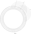
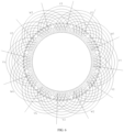
FIG. 1 is a schematic diagram of a first time embedding by using the automatic wire embedding method for single-and double-layer windings based on lamination having large-and small-slots of the present invention; -
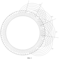
FIG. 2 is a schematic diagram of a second time embedding by using automatic wire embedding method for single-and double-layer windings based on lamination having large-and small-slots of the present invention; -
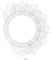
FIG. 3 is a schematic diagram of a third time embedding by using the automatic wire embedding method for single-and double-layer windings based on lamination having large-and small-slots of the present invention; -
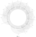
FIG. 4 is a schematic diagram of a fourth time embedding by using the automatic wire embedding method for single-and double-layer windings based on lamination having large-and small-slots of the present invention; -
FIG. 5 is a schematic diagram of a fifth time embedding by using the automatic wire embedding method for single-and double-layer windings based on lamination having large-and small-slots of the present invention; -
FIG. 6 is a schematic diagram of a sixth time embedding by using the automatic wire embedding method for single-and double-layer windings based on lamination having large-and small-slots of the present invention. - In order to make the object, technical solution and advantages of the present invention more clear, the technical solution of the present invention will be described clearly and completely with specific embodiments of the present invention and corresponding drawings. Obviously, the described embodiment is only part of, rather than all of the embodiments of the present invention. Based on the embodiment of the present invention, all other embodiments obtained by ordinary technicians in the field without creative labor belong to the scope of protection of the present invention.
- As shown in
FIG. 1 to FIG. 6 , an embodiment of the present invention provides an automatic wire embedding method for single-and double-layer windings based on lamination having large-and small-slots. In the present invention, number of stator slots of a motor of which windings to be embedded is 72, and number of phases of the motor is three, the method comprises: performing six times embedding to complete the wire embedding of the winding, and completing embedding of respective one pole-phase group coil for two phases among three phases in each time embedding, wherein the windings are single-and double-layer windings, and each pole-phase group coil consists of five coils, in which a coil with a largest span is a single-layer coil and is pulled into small stator slots, and the other four coils are double-layer coils and are pulled into large stator slot. - Further, in the automatic wire embedding method for single-and double-layer windings based on lamination having large-and small-slots provided in the embodiment of the present invention, the first time of embedding is implemented as follows: taking respective one pole-phase group coil of two phases among three phases, arranging the two pole-phase group coils in an overlapping manner, winding all the coils of the pole-phase group coils on coil cups according to the corresponding span of each coil of the pole-phase group coils, pulling the single-layer coils with the largest span into the small stator slots, and puling the other double-layer coils into the large stator slots.
- Further, in the automatic wire embedding method for single-and double-layer windings based on lamination having large-and small-slots provided in the embodiment of the present invention, the second time of embedding is implemented as follows: taking respective one pole-phase group coil of two phases among three phases, arranging the two pole-phase group coils in an overlapping manner, winding all the coils of the pole-phase group coils on coil cups according to the corresponding span of each coil of the pole-phase group coils, rotating the
stator core 60 degrees clockwise from an origin, pulling the single-layer coils with the largest span into the small stator slots, and puling the other double-layer coils into the large stator slots. - Further, in the automatic wire embedding method for single-and double-layer windings based on lamination having large-and small-slots provided in the embodiment of the present invention, the third time of embedding is implemented as follows: taking respective one pole-phase group coil of two phases among three phases, arranging the two pole-phase group coils in an overlapping manner, winding all the coils of the pole-phase group coils on coil cups according to the corresponding span of each coil of the pole-phase group coils, rotating the stator core 120 degrees clockwise from the origin, pulling the single-layer coils with the largest span into the small stator slots, and puling the other double-layer coils into the large stator slots.
- Further, in the automatic wire embedding method for single-and double-layer windings based on lamination having large-and small-slots provided in the embodiment of the present invention, the fourth time of embedding is implemented as follows: taking respective one pole-phase group coil of two phases among three phases, arranging the two pole-phase group coils in an overlapping manner, winding all the coils of the pole-phase group coils on coil cups according to the corresponding span of each coil of the pole-phase group coils, rotating the
stator core 60 degrees counterclockwise from the origin, pulling the single-layer coils with the largest span into the small stator slots, and puling the other double-layer coils into the large stator slots. - Further, in the automatic wire embedding method for single-and double-layer windings based on lamination having large-and small-slots provided in the embodiment of the present invention, the fifth time of embedding is implemented as follows: taking respective one pole-phase group coil of two phases among three phases, arranging the two pole-phase group coils in an overlapping manner, winding all the coils of the pole-phase group coils on coil cups according to the corresponding span of each coil of the pole-phase group coils, rotating the stator core 120 degrees counterclockwise from the origin, pulling the single-layer coils with the largest span into the small stator slots, and puling the other double-layer coils into the large stator slots.
- Further, in the automatic wire embedding method for single-and double-layer windings based on lamination having large-and small-slots provided in the embodiment of the present invention, the sixth time of embedding is implemented as follows: taking respective one pole-phase group coil of two phases among three phases, arranging the two pole-phase group coils in an overlapping manner, winding all the coils of the pole-phase group coils on coil cups according to the corresponding span of each coil of the pole-phase group coils, rotating the stator core 180 degrees counterclockwise from the origin, pulling the single-layer coils with the largest span into the small stator slots, and puling the other double-layer coils into the large stator slots.
- In the embodiment of the present invention, by performing six times embedding according to the method defined above, the coil sides are arranged in the large stator slots in up-and-down manner, thus effectively shortens the winding half turn length; through the clockwise rotation of the stator core from the origin during the second and the third embedding and the counterclockwise rotation of the stator core from the origin during the fourth, the fifth and the sixth embedding, it is effectively ensured that for each phase, half of the coil sides are placed at the bottom of the slot core slot and half of the coil sides are placed at the opening of the slot core.
- Further, in the automatic wire embedding method for single-and double-layer windings based on lamination having large-and small-slots provided in the embodiment of the present invention, slot insulations are respectively disposed in the large stator slots and the small stator slots according to slot-shaped perimeters.
- Further, in the automatic wire embedding method for single-and double-layer windings based on lamination having large-and small-slots provided in the embodiment of the present invention, the small stator slot is a single-layer slot, and a single-layer coil is pulled into the small stator slot, followed by punching of cover paper, thereby effectively shortening the core length with the same power.
- Further, in the automatic wire embedding method for single-and double-layer windings based on lamination having large-and small-slots provided in the embodiment of the present invention, the large stator slot is a double-layer slot, and a double-layer coil is pressed by a coil pressing die after a lower layer side of the coil being embedded in the large stator slot, and an inter-layer phase segregated paper is punched, which is beneficial to the slot entry of the upper layer side of the coils and the punching of the cover paper, thus improving the product qualification rate.
- In order to make the technical solution of the present invention more clear, the technical solution of the present invention will be described clearly and completely with specific examples. Obviously, the described embodiment is only part of, rather than all of the embodiments of the present invention.
- In this
embodiment 1, the number of stator slots is 72 (stator slots No.1 to No.72), the windings are 4-pole single-and double-layer concentric windings, and the number of motor phases is three. - The wire embedding of the winding is completed by performing six times embedding, and the embedding of respective one pole-phase group coil for two phases among three phases is completed in each time embedding, wherein the windings are single-and double-layer windings, and each pole-phase group coil consists of five coils, wherein a coil with a largest span is a single-layer coil and is pulled into small stator slots, and the other four coils are double-layer coils and are pulled into large stator slots.
- Referring to
FIG. 1 , in the first time of embedding, respective one pole-phase group coil U1 and W1 of two phases among three phases is wound, the two pole-phase group coils U1 and W1 are arranged in an overlapping manner, wherein the pole-phase group coil U1 occupies stator slots No.1-5 and No. 14-18, and the spans of the five coils of the pole-phase group coil U1 are No.1 to No.18, No.2 to No.17, No.3 to No.16, No.4 to No.15, No.5 to No.14, wherein the pole-phase group coil W1 occupies stator slots No.7-11 and No.20-24, and the spans of the five coils of the pole-phase group coil W1 are No.7 to No.24, No.8 to No.23, No.9 to No.22, No.10 to No.21, No.11 to No.20; all the coils of the pole-phase group coils U1 and W1 are wound on coil cups according to the corresponding span of each coil of the pole-phase group coils U1 and W1. Then the coils are drawn into the corresponding stator slots after being wound, wherein the coils with the largest spans No.1 to No.18 and No.7 and No.24 are single-layer coils and are pulled into small stator slots No.1 and No.18, No.7 and No.24, followed by punching of cover paper; wherein the other coils are double-layer coils and are pulled into large stator slots No.2, No.17, No.3, No.16, No.4, No.15, No.5, No.14, No.8, No.23, No.9, No.22, No.10, No.21, No.11, No.20, followed by punching of inter-layer phase segregated paper and coil pressing in the corresponding double-layer slots with a coil pressing die. - Referring to
FIG. 2 , in the second time of embedding, respective one pole-phase group coil V1 and U2 of two phases among three phases is wound, the two pole-phase group coils V1 and U2 are arranged in an overlapping manner, wherein the pole-phase group coil V1 occupies stator slots No.13-17 and No.26-30, and the spans of the five coils of the pole-phase group coil V1 are No.13 to No.30, No.14 to No.29, No.15 to No.28, No.16 to No.27, No.17 to No.26, wherein the pole-phase group coil U2 occupies stator slots No.19-23 and No.32-36, and the spans of the five coils of the pole-phase group coil U2 are No.19 to No.36, No.20 to No.35, No.21 to No.34, No.22 to No.33, No.23 to No.32; all the coils of the pole-phase group coils V1 and U2 are wound on coil cups according to the corresponding span of each coil of the pole-phase group coils V1 and U2. The stator core rotates 60 degrees clockwise from an origin. Then the coils are drawn into the corresponding stator slots after being wound, wherein the coils with the largest spans No.13 to No.30 and No.19 and No.36 are single-layer coils and are pulled into small stator slots No.13 and No.30, No.19 and No.36, followed by punching of cover paper; wherein the other coils are double-layer coils and are pulled into large stator slots No.14, No.29, No.15, No.28, No.16, No.27, No.17, No.26, No.20, No.35, No.21, No.34, No.22, No.33, No.23, No.32, followed by punching of inter-layer phase segregated paper and coil pressing in the corresponding double-layer slots with a coil pressing die. - Referring to
FIG. 3 , in the third time of embedding, respective one pole-phase group coil W2 and V2 of two phases among three phases is wound, the two pole-phase group coils W2 and V2 are arranged in an overlapping manner, wherein the pole-phase group coil W2 occupies stator slots No.25-29 and No.38-42, and the spans of the five coils of the pole-phase group coil W2 are No.25 to No.42, No.26 to No.41, No.27 to No.40, No.28 to No.39, No.29 to No.38, wherein the pole-phase group coil V2 occupies stator slots No.31-35 and No.44-48, and the spans of the five coils of the pole-phase group coil V2 are No.31 to No.48, No.32 to No.47, No.33 to No.46, No.34 to No.45, No.35 to No.44; all the coils of the pole-phase group coils W2 and V2 are wound on coil cups according to the corresponding span of each coil of the pole-phase group coils W2 and V2. The stator core rotates 120 degrees clockwise from the origin. Then the coils are drawn into the corresponding stator slots after being wound, wherein the coils with the largest spans No.25 to No.42 and No.31 and No.48 are single-layer coils and are pulled into small stator slots No.25 and No.42, No.31 and No.48, followed by punching of cover paper; wherein the other coils are double-layer coils and are pulled into large stator slots No.26, No.41, No.27, No.40, No.28, No.39, No.29, No.38, No.32, No.47, No.33, No.46, No.34, No.45, No.35, No.44, followed by punching of inter-layer phase segregated paper and coil pressing in the corresponding double-layer slots with a coil pressing die. - Referring to
FIG. 4 , in the fourth time of embedding, respective one pole-phase group coil V3 and W3 of two phases among three phases is wound, the two pole-phase group coils V3 and W3 are arranged in an overlapping manner, wherein the pole-phase group coil V3 occupies stator slots No.8-12 and No.67-71, and the spans of the five coils of the pole-phase group coil V3 are No.12 to No.67, No.11 to No.68, No.10 to No.69, No.9 to No.70, No.8 to No.71, wherein the pole-phase group coil W3 occupies stator slots No.2-6 and No.61-65, and the spans of the five coils of the pole-phase group coil W3 are No.6 to No.61, No.5 to No.62, No.4 to No.63, No.3 to No.64, No.2 to No.65; all the coils of the pole-phase group coils V3 and W3 are wound on coil cups according to the corresponding span of each coil of the pole-phase group coils V3 and W3. The stator core rotates 60 degrees counterclockwise from the origin. Then the coils are drawn into the corresponding stator slots after being wound, wherein the coils with the largest spans No.12 to No.67 and No.6 and No.61 are single-layer coils and are pulled into small stator slots No.12 and No.67, No.6 and No.61, followed by punching of cover paper; wherein the other coils are double-layer coils and are pulled into large stator slots No.11, No.68, No.10, No.69, No.9, No.70, No.8, No.71, No.5, No.62, No.4, No.63, No.3, No.64, No.2, No.65, followed by punching of inter-layer phase segregated paper and coil pressing in the corresponding double-layer slots with a coil pressing die. - Referring to
FIG. 5 , in the fifth time of embedding, respective one pole-phase group coil U3 and V4 of two phases among three phases is wound, the two pole-phase group coils U3 and V4 are arranged in an overlapping manner, wherein the pole-phase group coil U3 occupies stator slots No.68-72 and No.55-59, and the spans of the five coils of the pole-phase group coil U3 are No.55 to No.72, No.56 to No.71, No.57 to No.70, No.58 to No.69, No.59 to No.68, wherein the pole-phase group coil V4 occupies stator slots No.62-66 and No.49-53, and the spans of the five coils of the pole-phase group coil V4 are No.49 to No.66, No.50 to No.65, No.51 to No.64, No.52 to No.63, No.53 to No.62; all the coils of the pole-phase group coils U3 and V4 are wound on coil cups according to the corresponding span of each coil of the pole-phase group coils U3 and V4. The stator core rotates 120 degrees counterclockwise from the origin. Then the coils are drawn into the corresponding stator slots after being wound, wherein the coils with the largest spans No.55 to No.72 and No.49 and No.66 are single-layer coils and are pulled into small stator slots No.55 and No.72, No.49 and No.66, followed by punching of cover paper; wherein the other coils are double-layer coils and are pulled into large stator slots No.56, No.71, No.57, No.70, No.58, No.69, No.59, No.68, No.50, No.65, No.51, No.64, No.52, No.63, No.53, No.62, followed by punching of inter-layer phase segregated paper and coil pressing in the corresponding double-layer slots with a coil pressing die. - Referring to
FIG. 6 , in the sixth time of embedding, respective one pole-phase group coil W4 and U4 of two phases among three phases is wound, the two pole-phase group coils W4 and U4 are arranged in an overlapping manner, wherein the pole-phase group coil W4 occupies stator slots No.56-60 and No.43-47, and the spans of the five coils of the pole-phase group coil W4 are No.43 to No.60, No.44 to No.59, No.45 to No.58, No.46 to No.57, No.47 to No.56, wherein the pole-phase group coil U4 occupies stator slots No.50-54 and No.37-41, and the spans of the five coils of the pole-phase group coil U4 are No.37 to No.54, No.38 to No.53, No.39 to No.52, No.40 to No.51, No.41 to No.50; all the coils of the pole-phase group coils W4 and U4 are wound on coil cups according to the corresponding span of each coil of the pole-phase group coils W4 and U4. The stator core rotates 180 degrees counterclockwise from the origin. Then the coils are drawn into the corresponding stator slots after being wound, wherein the coils with the largest spans No.43 to No.60 and No.37 and No.54 are single-layer coils and are pulled into small stator slots No.43 and No.60, No.37 and No.54, followed by punching of cover paper; wherein the other coils are double-layer coils and are pulled into large stator slots No.44, No.59, No.45, No.58, No.46, No.57, No.47, No.56, No.38, No.53, No.39, No.52, No.40, No.51, No.41, No.50, followed by punching of inter-layer phase segregated paper and coil pressing in the corresponding double-layer slots with a coil pressing die. - After wire embedding according to the above method, the arrangement of coils is close to the manual embedding form, in which the V-phase is completely the same as the manual embedding form with side cover, four groups of coil sides are all arranged in up-and-down manner. Two groups of coils for the U and W phases are the same as the manual embedding form, the coil sides are in up-and-down manner, one group of coil sides being all up and one group of coil sides being all down. From the point of view of the symmetry of the magnetic circuit of each phase conductor of the whole motor, the coil groups in the three-phase winding are completely balanced, and for each phase, half of the coil sides are placed at the bottom of the slot core slot and half of the coil sides are placed at the opening of the slot core.
- To sum up, compared with the prior art, the automatic wire embedding method for single-and double-layer windings based on lamination having large-and small-slots in the embodiment of the present invention has the following advantages and beneficial effects:
- (1) The automatic wire embedding method for single-and double-layer windings based on lamination having large-and small-slots ensures the symmetrical distribution of each phase conductor in the core slot and the end space, reduces the unevenness of no-load current and short-circuit current of the whole machine, and reduces stray loss.
- (2) Reasonable arrangement of the positions of the coil pressing dies according to the wire embedding sequence is beneficial to the slot entry of the upper layer side of the coils and the punching of the cover paper, thus improving the product qualification rate.
- (3) In the method, six times embedding and arranging two pole-phase group coils in an overlapping manner (arranging one pole-phase group coil at an upper position and the other pole-phase group coil at a lower position) are adopted, which effectively shortens the winding half turn length and reduces the copper weight of the stator, thus reducing the material cost of the motor and the copper loss of the motor; at the same time, the stability of interphase insulation placement is improved, and the risk of interphase fault of products is further reduced; the single-layer coil is pulled into the small stator slots, which effectively shortens the length of the core with the same power, and improves the overall efficiency of the motor by 0.7%.
- It should be noted that in this paper, unless otherwise specified and limited, the term "connection" or its synonyms should be broadly understood. For example, "connection" can be a fixed connection or a detachable connection; it can be a mechanical connection or an electrical connection; it may be a direct connection or indirect connection through an intermediary, and it may be the internal communication between two elements or the interaction between two elements. For those skilled in the art, the specific meanings of the above terms in the present invention can be understood according to specific conditions. Moreover, expressions such as "first" and "second" are only used to distinguish one entity or operation from another entity or operation, and do not necessarily require or imply any such actual relationship or order between these entities or operations. Meanwhile, the terms "including", "comprising" or any other variation thereof are intended to cover non-exclusive inclusion, so that a process, method, article or equipment including a series of elements includes not only those elements, but also other elements not explicitly listed or elements inherent to such process, method, article or equipment. In addition, the words "front", "back", "left", "right", "upper" and "lower" in this paper refer to the placement state shown in the drawings.
- Finally, it should be explained that the above embodiments are only used to illustrate, rather than to limit the technical solution of the present invention. Although the present invention has been described in detail with reference to the foregoing embodiments, those skilled in the art should understand that it is still possible to modify the technical solutions described in the foregoing embodiments, or to replace some technical features with equivalents; However, these modifications or substitutions do not make the essence of the corresponding technical solutions deviate from the spirit and scope of the technical solutions of various embodiments of the present invention.
Claims (4)
- An automatic wire embedding method for single-and double-layer windings based on lamination having large-and small-slots, wherein number of stator slots of a motor of which windings to be embedded is 72 including stator slots No. 1 to No.72, and number of phases of the motor is three, wherein the method comprises: performing six times embedding to complete the wire embedding of the windings, and embedding of respective one pole-phase group coil for two phases among three phases in each time embedding, wherein the windings are single-and double-layer windings, and each pole-phase group coil consists of five coils in which a coil with a largest span is a single-layer coil and is pulled into small stator slots and the other four coils are double-layer coils and are pulled into large stator slots, wherein,a first time of embedding comprises: taking respective one pole-phase group coil U1 and W1 of two phases among three phases, arranging the two pole-phase group coils U1 and W1 in an overlapping manner, wherein the pole-phase group coil U1 occupies stator slots No.1-5 and No.14-18, and the spans of the five coils of the pole-phase group coil U1 are No.1 to No.18, No.2 to No.17, No.3 to No.16, No.4 to No.15, No.5 to No.14, wherein the pole-phase group coil W1 occupies stator slots No.7-11 and No.20-24, and the spans of the five coils of the pole-phase group coil W1 are No.7 to No.24, No.8 to No.23, No.9 to No.22, No.10 to No.21, No.11 to No.20; winding all the coils of the pole-phase group coils U1 and W1 on coil cups according to the corresponding span of each coil of the pole-phase group coils U1 and W1, pulling single-layer coils with the largest span into the small stator slots, and puling other double-layer coils into the large stator slots;a second time of embedding comprises: taking respective one pole-phase group coil V1 and U2 of two phases among three phases, arranging the two pole-phase group coils V1 and U2 in an overlapping manner, wherein the pole-phase group coil V1 occupies stator slots No. 13-17 and No. 26-30, and the spans of the five coils of the pole-phase group coil V1 are No.13 to No.30, No.14 to No.29, No.15 to No.28, No.16 to No.27, No.17 to No.26, wherein the pole-phase group coil U2 occupies stator slots No. 19-23 and No. 32-36, and the spans of the five coils of the pole-phase group coil U2 are No.19 to No.36, No.20 to No.35, No.21 to No.34, No.22 to No.33, No.23 to No.32; winding all the coils of the pole-phase group coils V1 and U2 on coil cups according to the corresponding span of each coil of the pole-phase group coils V1 and U2; rotating stator core 60 degrees clockwise from an origin; pulling single-layer coils with the largest span into the small stator slots, and pulling other double-layer coils into the large stator slots;a third time of embedding comprises: taking respective one pole-phase group coil W2 and V2 of two phases among three phases, arranging the two pole-phase group coils W2 and V2 in an overlapping manner, wherein the pole-phase group coil W2 occupies stator slots No. 25-29 and No. 38-42, and the spans of the five coils of the pole-phase group coil W2 are No.25 to No.42, No.26 to No.41, No.27 to No.40, No.28 to No.39, No.29 to No.38, wherein the pole-phase group coil V2 occupies stator slots No. 31-35 and No. 44-48, and the spans of the five coils of the pole-phase group coil V2 are No.31 to No.48, No.32 to No.47, No.33 to No.46, No.34 to No.45, No.35 to No.44; winding all the coils of the pole-phase group coils W2 and V2 on coil cups according to the corresponding span of each coil of the pole-phase group coils W2 and V2; rotating the stator core 120 degrees clockwise from the origin; pulling single-layer coils with the largest span into the small stator slots, and pulling other double-layer coils into the large stator slots;a fourth time of embedding comprise: taking respective one pole-phase group coil V3 and W3 of two phases among three phases, arranging the two pole-phase group coils V3 and W3 in an overlapping manner, wherein the pole-phase group coil V3 occupies stator slots No. 8-12 and No. 67-71, and the spans of the five coils of the pole-phase group coil V3 are No.12 to No.67, No.11 to No.68, No.10 to No.69, No.9 to No.70, No.8 to No.71, wherein the pole-phase group coil W3 occupies stator slots No. 2-6 and No. 61-65, and the spans of the five coils of the pole-phase group coil W3 are No.6 to No.61, No.5 to No.62, No.4 to No.63, No.3 to No.64, No.2 to No.65; winding all the coils of the pole-phase group coils V3 and W3 on coil cups according to the corresponding span of each coil of the pole-phase group coils V3 and W3; rotating the stator core 60 degrees counterclockwise from the origin; pulling single-layer coils with the largest span into the small stator slots, and pulling other double-layer coils into the large stator slots;a fifth time of embedding comprises: taking respective one pole-phase group coil U3 and V4 of each of two phases among three phases, arranging the two pole-phase group coils U3 and V4 in an overlapping manner, wherein the pole-phase group coil U3 occupies stator slots No. 68-72 and No. 55-59, and the spans of the five coils of the pole-phase group coil U3 are No.55 to No.72, No.56 to No.71, No.57 to No.70, No.58 to No.69, No.59 to No.68, wherein the pole-phase group coil V4 occupies stator slots No. 62-66 and No. 49-53, and the spans of the five coils of the pole-phase group coil V4 are No.49 to No.66, No.50 to No.65, No.51 to No.64, No.52 to No.63, No.53 to No.62; winding all the coils of the pole-phase group coils U3 and V4 on coil cups according to the corresponding span of each coil of the pole-phase group coils U3 and V4; rotating the stator core 120 degrees counterclockwise from the origin; pulling single-layer coils with the largest span into the small stator slots, and pulling other double-layer coils into the large stator slots; anda sixth time of embedding comprises: taking respective one pole-phase group coil W4 and U4 of each of two phases among three phases, arranging the two pole-phase group coils W4 and U4 in an overlapping manner, wherein the pole-phase group coil W4 occupies stator slots No. 56-60 and No. 43-47, and the spans of the five coils of the pole-phase group coil W4 are No.43 to No.60, No.44 to No.59, No.45 to No.58, No.46 to No.57, No.47 to No.56, wherein the pole-phase group coil U4 occupies stator slots No. 50-54 and No. 37-41, and the spans of the five coils of the pole-phase group coil U4 are No.37 to No.54, No.38 to No.53, No.39 to No.52, No.40 to No.51, No.41 to No.50; winding all the coils of the pole-phase group coils W4 and U4 on coil cups according to the corresponding span of each coil of the pole-phase group coils W4 and U4; rotating the stator core 180 degrees counterclockwise from the origin; pulling single-layer coils with the largest span into the small stator slots, and pulling other double-layer coils into the large stator slots.
- The automatic wire embedding method for single-and double-layer windings based on lamination having large-and small-slots according to claim 1, wherein slot insulations based on slot-shaped perimeters are respectively disposed in the large stator slots and the small stator slots.
- The automatic wire embedding method for single-and double-layer windings based on lamination having large-and small-slots according to claim 1, wherein the small stator slot is a single-layer slot, and a single-layer coil is pulled into the small stator slot, followed by punching of cover paper.
- The automatic wire embedding method for single-and double-layer windings based on lamination having large-and small-slots according to claim 1, wherein the large stator slot is a double-layer slot, and a double-layer coil is pressed by a coil pressing die after a lower layer side of the coil being embedded in the large stator slot, and an inter-layer phase segregated paper is punched.
Applications Claiming Priority (2)
| Application Number | Priority Date | Filing Date | Title |
|---|---|---|---|
| CN202410254455.XA CN117833575B (en) | 2024-03-06 | 2024-03-06 | Single-double layer winding automatic wire embedding method based on large and small slot punching sheets |
| PCT/CN2024/092792 WO2025030959A1 (en) | 2024-03-06 | 2024-05-13 | Method for automatically inserting single-layer and double-layer windings on basis of large and small slot punching |
Publications (4)
| Publication Number | Publication Date |
|---|---|
| EP4546625A1 true EP4546625A1 (en) | 2025-04-30 |
| EP4546625A4 EP4546625A4 (en) | 2025-10-22 |
| EP4546625C0 EP4546625C0 (en) | 2026-02-25 |
| EP4546625B1 EP4546625B1 (en) | 2026-02-25 |
Family
ID=90513910
Family Applications (1)
| Application Number | Title | Priority Date | Filing Date |
|---|---|---|---|
| EP24821737.4A Active EP4546625B1 (en) | 2024-03-06 | 2024-05-13 | Method for automatically inserting single-layer and double-layer windings on basis of large and small slot punching |
Country Status (3)
| Country | Link |
|---|---|
| EP (1) | EP4546625B1 (en) |
| CN (1) | CN117833575B (en) |
| WO (1) | WO2025030959A1 (en) |
Families Citing this family (2)
| Publication number | Priority date | Publication date | Assignee | Title |
|---|---|---|---|---|
| CN116707195B (en) * | 2023-03-13 | 2024-07-19 | 浙江大学 | A double-layer winding layout method suitable for asymmetric winding motors |
| CN117833575B (en) * | 2024-03-06 | 2024-06-07 | 山西电机制造有限公司 | Single-double layer winding automatic wire embedding method based on large and small slot punching sheets |
Family Cites Families (19)
| Publication number | Priority date | Publication date | Assignee | Title |
|---|---|---|---|---|
| US5898251A (en) * | 1995-08-18 | 1999-04-27 | Kabushiki Kaisha Toshiba | Method of making armature winding of double-layer concentric-wound or lap-winding type for dynamoelectric machine |
| JP2002044893A (en) * | 2000-07-19 | 2002-02-08 | Hitachi Ltd | Rotating electric machine or linear motor and its stator |
| CN101165992B (en) * | 2006-10-16 | 2011-04-06 | 王怀林 | q=3-8 concentric type variable crosssection winding, small and big groove stator piece and winding parameter |
| US8069555B2 (en) * | 2010-02-18 | 2011-12-06 | Tesla Motors, Inc. | Manufacturing method utilizing a dual layer winding pattern |
| CN201904670U (en) * | 2010-12-06 | 2011-07-20 | 泰豪科技股份有限公司 | Fractional slot single-layer and double-layer lap winding of servo permanent magnet synchronous motor |
| CN101986513B (en) * | 2010-12-06 | 2012-11-14 | 泰豪科技股份有限公司 | Fractional slot single and double-layer lap winding for servo permanent magnet synchronous motor |
| CN103633798A (en) * | 2013-12-17 | 2014-03-12 | 江苏大中电机股份有限公司 | Wire inserting process for odd-or-even concentric unequal-turn stator windings |
| CN204652187U (en) * | 2015-05-31 | 2015-09-16 | 河北弛神电机制造有限公司 | Electric vehicle high-power odd number fractional-slot motor |
| CN104917348B (en) * | 2015-05-31 | 2018-04-20 | 河北弛神电机制造有限公司 | The high-power odd number fractional-slot motor of electric car |
| JP6203785B2 (en) * | 2015-06-25 | 2017-09-27 | ファナック株式会社 | Electric motor having 8-shaped connecting coil and manufacturing method thereof |
| CN105978202B (en) * | 2016-06-21 | 2018-04-03 | 天津大学 | A kind of pole three phase alternating current motor list double layered stator winding of 24 groove 2 |
| DE202017107387U1 (en) * | 2017-12-05 | 2017-12-18 | Ebm-Papst Mulfingen Gmbh & Co. Kg | Multi-tooth coil winding for a 2-phase induction machine |
| CN115347750A (en) * | 2021-05-13 | 2022-11-15 | 德州恒力电机有限责任公司 | Motor double-layer winding machine wire inserting method |
| CN214674607U (en) * | 2021-06-08 | 2021-11-09 | 浙江金龙电机股份有限公司 | Single-double layer winding of three-phase motor |
| CN113629905A (en) * | 2021-07-15 | 2021-11-09 | 鑫磊压缩机股份有限公司 | Motor and stator thereof, stator punching sheet and winding wiring structure |
| WO2024026824A1 (en) * | 2022-08-05 | 2024-02-08 | 宁德时代(上海)智能科技有限公司 | Flat wire electric motor and stator thereof |
| CN115549405B (en) * | 2022-10-19 | 2025-10-10 | 江苏大学 | A design method for phase group modular structure to improve the fault tolerance of permanent magnet motor and consider low torque ripple |
| CN117578775A (en) * | 2023-11-22 | 2024-02-20 | 天津大学 | 4-pole 18-slot three-phase permanent magnet synchronous motor single and double layer hybrid chain winding |
| CN117833575B (en) * | 2024-03-06 | 2024-06-07 | 山西电机制造有限公司 | Single-double layer winding automatic wire embedding method based on large and small slot punching sheets |
-
2024
- 2024-03-06 CN CN202410254455.XA patent/CN117833575B/en active Active
- 2024-05-13 WO PCT/CN2024/092792 patent/WO2025030959A1/en active Pending
- 2024-05-13 EP EP24821737.4A patent/EP4546625B1/en active Active
Also Published As
| Publication number | Publication date |
|---|---|
| CN117833575A (en) | 2024-04-05 |
| WO2025030959A1 (en) | 2025-02-13 |
| EP4546625C0 (en) | 2026-02-25 |
| EP4546625A4 (en) | 2025-10-22 |
| CN117833575B (en) | 2024-06-07 |
| EP4546625B1 (en) | 2026-02-25 |
Similar Documents
| Publication | Publication Date | Title |
|---|---|---|
| EP4546625B1 (en) | Method for automatically inserting single-layer and double-layer windings on basis of large and small slot punching | |
| US12261496B2 (en) | Six-phase flat wire wave winding structure, six-phase motor, powertrain, and vehicle | |
| US5801334A (en) | Conductor (turn) insulation system for coils in high voltage machines | |
| WO2019233041A1 (en) | Flat-wire continuous wave-wound staggered winding and stator comprising the same | |
| EP1174982A2 (en) | Stator for rotary electric machine or linear motor | |
| CA2256473A1 (en) | Rotating electric machines with magnetic circuit for high voltage and method for manufacturing the same | |
| CN218920101U (en) | Vehicle, power assembly, flat wire motor and stator thereof | |
| JP2011172476A (en) | Triple layer winding pattern, and methods of manufacturing the same | |
| US6114790A (en) | Sixteen and thirty two slot three phase induction motor winding | |
| US20020140312A1 (en) | Method for manufacturing an armature of an internal rotor type electric machine and the armature manufactured by such method | |
| CN213990307U (en) | Motor stator and motor | |
| EP4391318B1 (en) | Six-pole 54-slot flat wire motor three-branch balancing winding and use method therefor | |
| CN111146892B (en) | Contact pin winding type motor stator and motor | |
| EP4231506A1 (en) | Flat wire stator and motor | |
| CN110504768A (en) | Stator module and motor | |
| CN213846351U (en) | Motor stator and motor | |
| CN117791991A (en) | An automatic winding and embedding process for single-layer windings of motors | |
| JPH07143697A (en) | Three-phase armature winding | |
| CN218976446U (en) | Lead structure of same-phase two sets of stator windings of permanent magnet wind driven generator | |
| JP3494729B2 (en) | Three-phase armature winding | |
| CN213585304U (en) | Motor stator and motor | |
| CN212033858U (en) | Motor stator and motor | |
| CN216216162U (en) | Motor stator and motor with same | |
| JPH0447551B2 (en) | ||
| CN207265765U (en) | A kind of side's copper wire motor stator structure |
Legal Events
| Date | Code | Title | Description |
|---|---|---|---|
| STAA | Information on the status of an ep patent application or granted ep patent |
Free format text: STATUS: UNKNOWN |
|
| STAA | Information on the status of an ep patent application or granted ep patent |
Free format text: STATUS: THE INTERNATIONAL PUBLICATION HAS BEEN MADE |
|
| PUAI | Public reference made under article 153(3) epc to a published international application that has entered the european phase |
Free format text: ORIGINAL CODE: 0009012 |
|
| STAA | Information on the status of an ep patent application or granted ep patent |
Free format text: STATUS: REQUEST FOR EXAMINATION WAS MADE |
|
| 17P | Request for examination filed |
Effective date: 20241230 |
|
| AK | Designated contracting states |
Kind code of ref document: A1 Designated state(s): AL AT BE BG CH CY CZ DE DK EE ES FI FR GB GR HR HU IE IS IT LI LT LU LV MC ME MK MT NL NO PL PT RO RS SE SI SK SM TR |
|
| A4 | Supplementary search report drawn up and despatched |
Effective date: 20250924 |
|
| RIC1 | Information provided on ipc code assigned before grant |
Ipc: H02K 15/085 20060101AFI20250918BHEP Ipc: H02K 3/28 20060101ALI20250918BHEP Ipc: H02K 3/12 20060101ALI20250918BHEP |
|
| GRAP | Despatch of communication of intention to grant a patent |
Free format text: ORIGINAL CODE: EPIDOSNIGR1 |
|
| STAA | Information on the status of an ep patent application or granted ep patent |
Free format text: STATUS: GRANT OF PATENT IS INTENDED |
|
| RIC1 | Information provided on ipc code assigned before grant |
Ipc: H02K 15/085 20060101AFI20251127BHEP Ipc: H02K 3/28 20060101ALI20251127BHEP Ipc: H02K 3/12 20060101ALI20251127BHEP |
|
| DAV | Request for validation of the european patent (deleted) | ||
| DAX | Request for extension of the european patent (deleted) | ||
| INTG | Intention to grant announced |
Effective date: 20251205 |
|
| GRAS | Grant fee paid |
Free format text: ORIGINAL CODE: EPIDOSNIGR3 |
|
| GRAA | (expected) grant |
Free format text: ORIGINAL CODE: 0009210 |
|
| STAA | Information on the status of an ep patent application or granted ep patent |
Free format text: STATUS: THE PATENT HAS BEEN GRANTED |
|
| AK | Designated contracting states |
Kind code of ref document: B1 Designated state(s): AL AT BE BG CH CY CZ DE DK EE ES FI FR GB GR HR HU IE IS IT LI LT LU LV MC ME MK MT NL NO PL PT RO RS SE SI SK SM TR |
|
| REG | Reference to a national code |
Ref country code: CH Ref legal event code: F10 Free format text: ST27 STATUS EVENT CODE: U-0-0-F10-F00 (AS PROVIDED BY THE NATIONAL OFFICE) Effective date: 20260225 Ref country code: GB Ref legal event code: FG4D |
|
| REG | Reference to a national code |
Ref country code: IE Ref legal event code: FG4D |
|
| U01 | Request for unitary effect filed |
Effective date: 20260225 |
|
| U07 | Unitary effect registered |
Designated state(s): AT BE BG DE DK EE FI FR IT LT LU LV MT NL PT RO SE SI Effective date: 20260302 |
|
| PGFP | Annual fee paid to national office [announced via postgrant information from national office to epo] |
Ref country code: TR Payment date: 20260326 Year of fee payment: 3 |
|
| U20 | Renewal fee for the european patent with unitary effect paid |
Year of fee payment: 3 Effective date: 20260327 |
|
| PG25 | Lapsed in a contracting state [announced via postgrant information from national office to epo] |
Ref country code: RS Free format text: LAPSE BECAUSE OF FAILURE TO SUBMIT A TRANSLATION OF THE DESCRIPTION OR TO PAY THE FEE WITHIN THE PRESCRIBED TIME-LIMIT Effective date: 20260525 |
|
| PG25 | Lapsed in a contracting state [announced via postgrant information from national office to epo] |
Ref country code: ES Free format text: LAPSE BECAUSE OF FAILURE TO SUBMIT A TRANSLATION OF THE DESCRIPTION OR TO PAY THE FEE WITHIN THE PRESCRIBED TIME-LIMIT Effective date: 20260225 |
|
| PG25 | Lapsed in a contracting state [announced via postgrant information from national office to epo] |
Ref country code: PL Free format text: LAPSE BECAUSE OF FAILURE TO SUBMIT A TRANSLATION OF THE DESCRIPTION OR TO PAY THE FEE WITHIN THE PRESCRIBED TIME-LIMIT Effective date: 20260225 |
|
| PG25 | Lapsed in a contracting state [announced via postgrant information from national office to epo] |
Ref country code: GR Free format text: LAPSE BECAUSE OF FAILURE TO SUBMIT A TRANSLATION OF THE DESCRIPTION OR TO PAY THE FEE WITHIN THE PRESCRIBED TIME-LIMIT Effective date: 20260526 |
|
| PG25 | Lapsed in a contracting state [announced via postgrant information from national office to epo] |
Ref country code: NO Free format text: LAPSE BECAUSE OF FAILURE TO SUBMIT A TRANSLATION OF THE DESCRIPTION OR TO PAY THE FEE WITHIN THE PRESCRIBED TIME-LIMIT Effective date: 20260525 |
|
| PG25 | Lapsed in a contracting state [announced via postgrant information from national office to epo] |
Ref country code: HR Free format text: LAPSE BECAUSE OF FAILURE TO SUBMIT A TRANSLATION OF THE DESCRIPTION OR TO PAY THE FEE WITHIN THE PRESCRIBED TIME-LIMIT Effective date: 20260225 |
|
| PG25 | Lapsed in a contracting state [announced via postgrant information from national office to epo] |
Ref country code: IS Free format text: LAPSE BECAUSE OF FAILURE TO SUBMIT A TRANSLATION OF THE DESCRIPTION OR TO PAY THE FEE WITHIN THE PRESCRIBED TIME-LIMIT Effective date: 20260625 |