EP4546610A1 - Conveyor band surface condition monitoring system - Google Patents
Conveyor band surface condition monitoring system Download PDFInfo
- Publication number
- EP4546610A1 EP4546610A1 EP23205086.4A EP23205086A EP4546610A1 EP 4546610 A1 EP4546610 A1 EP 4546610A1 EP 23205086 A EP23205086 A EP 23205086A EP 4546610 A1 EP4546610 A1 EP 4546610A1
- Authority
- EP
- European Patent Office
- Prior art keywords
- energy
- conveyor band
- microwave
- surface condition
- monitoring system
- Prior art date
- Legal status (The legal status is an assumption and is not a legal conclusion. Google has not performed a legal analysis and makes no representation as to the accuracy of the status listed.)
- Granted
Links
Images

Classifications
-
- H—ELECTRICITY
- H02—GENERATION; CONVERSION OR DISTRIBUTION OF ELECTRIC POWER
- H02J—ELECTRIC POWER NETWORKS; CIRCUIT ARRANGEMENTS OR SYSTEMS FOR SUPPLYING OR DISTRIBUTING ELECTRIC POWER; SYSTEMS FOR STORING ELECTRIC ENERGY
- H02J50/00—Circuit arrangements or systems for wireless supply or distribution of electric power
- H02J50/001—Energy harvesting or scavenging
-
- B—PERFORMING OPERATIONS; TRANSPORTING
- B65—CONVEYING; PACKING; STORING; HANDLING THIN OR FILAMENTARY MATERIAL
- B65G—TRANSPORT OR STORAGE DEVICES, e.g. CONVEYORS FOR LOADING OR TIPPING, SHOP CONVEYOR SYSTEMS OR PNEUMATIC TUBE CONVEYORS
- B65G43/00—Control devices, e.g. for safety, warning or fault-correcting
- B65G43/02—Control devices, e.g. for safety, warning or fault-correcting detecting dangerous physical condition of load carriers, e.g. for interrupting the drive in the event of overheating
-
- H—ELECTRICITY
- H02—GENERATION; CONVERSION OR DISTRIBUTION OF ELECTRIC POWER
- H02J—ELECTRIC POWER NETWORKS; CIRCUIT ARRANGEMENTS OR SYSTEMS FOR SUPPLYING OR DISTRIBUTING ELECTRIC POWER; SYSTEMS FOR STORING ELECTRIC ENERGY
- H02J50/00—Circuit arrangements or systems for wireless supply or distribution of electric power
- H02J50/20—Circuit arrangements or systems for wireless supply or distribution of electric power using microwaves or radio frequency waves
- H02J50/27—Circuit arrangements or systems for wireless supply or distribution of electric power using microwaves or radio frequency waves characterised by the type of receiving antennas, e.g. rectennas
-
- H—ELECTRICITY
- H02—GENERATION; CONVERSION OR DISTRIBUTION OF ELECTRIC POWER
- H02J—ELECTRIC POWER NETWORKS; CIRCUIT ARRANGEMENTS OR SYSTEMS FOR SUPPLYING OR DISTRIBUTING ELECTRIC POWER; SYSTEMS FOR STORING ELECTRIC ENERGY
- H02J50/00—Circuit arrangements or systems for wireless supply or distribution of electric power
- H02J50/40—Circuit arrangements or systems for wireless supply or distribution of electric power using two or more transmitting or receiving devices
- H02J50/402—Circuit arrangements or systems for wireless supply or distribution of electric power using two or more transmitting or receiving devices the two or more transmitting or the two or more receiving devices being integrated in the same unit, e.g. power mats with several coils or antennas with several sub-antennas
Definitions
- the invention relates to a product conveyor band surface condition monitoring system for uninterruptable conveyor band operation in a harsh environment.
- a wide variety of sensors are utilized to monitor and control state of a conveyor surface.
- condition of a conveyor surface should meet specific hygienic norms and technological requirements set for the food industry.
- Warmed chemical detergents are usually used for the conveyor's surface washing, and thereafter they are rinsed on the go.
- penetration of acidic and alkaline substrates from the conveyor's surface to the products is not tolerated.
- electronic equipment for monitoring conveyor conditions should be protected from the harsh environment.
- Wireless communication is commonly used to transfer data from moving sensors to data collection hubs.
- the power supply of sensors using changeable or rechargeable batteries is generally not acceptable since changing batteries or their charging calls for interruption of technological processes, losses in production, and additional time consumption.
- Energy harvesting, energy storing, and supplying to conveyor surface condition monitoring system integrated into a moving conveyor band allows avoiding the application of changeable batteries and improves the productivity of a conveyor.
- Different energy harvesting systems are proposed for a variety of applications like systems with wireless sensors, room condition monitoring systems, and different energy harvesting methods in conveyors.
- US patent application, publication No.: US20180139517 discloses a building's wireless sensor system, where temperature, humidity, etc. sensors distributed in different places of the building are charged by radio frequency (RF) energy harvesters, which accumulate energy of electromagnetic field transmitted from data hubs emitting RF waves.
- RF radio frequency
- European patent application, publication No.: EP2643244 discloses energy-harvesting conveyor belts and methods for power supply by harvesting ambient RF energy for electronic units installed in such conveyor belts.
- Disclosed transmitting antennas are coils of transmitters closely located to a conveyor belt, where the harvester receiver coils are embedded in a conveyor band. Such technology is widely used in RFID applications working at close distances and low RF carrier frequencies.
- the disclosed method and system limit dimensions of products that can be transported by a conveyor band and are not suitable to operate at microwave frequencies when the receiver and emitter are substantially apart from each other.
- the present invention is dedicated to overcoming the above shortcomings and producing further advantages over prior art.
- the conveyor band surface condition monitoring system comprises at least one energy harvesting segment of a segmented conveyor band comprising integrated electronics and various sensors, integrated into at least one segment of the conveyor band.
- the sensors may be attached to the surface of the segment of the segmented conveyor band.
- the system further comprises a wireless data hub.
- the data hub is such that operates on standard frequencies above 1 GHz and communicates with distributed data nodes of the energy harvesting segments.
- the integrated electronics of the energy harvesting segment comprises an array of microwave energy harvesting cells, an energy storage monitoring unit, and a data processing node.
- the array of microwave energy harvesting cells is an array of flat antennas with microwave rectifiers and capacitors.
- at least one sensor is either encapsulated into the body of the energy harvesting segment or mounted on its surface facing the wireless data hub when the harvesting segment is moving at the upper part of the conveyor band between the wireless data hub and lower part of a conveyor band.
- the various sensors for example are sensors used for control of dosing of detergents and rinsing liquids, temperature, humidity, and other parameters of the surface of the segment of the conveyor band.
- the data hub plays a twofold role. On the one hand, it provides communication with nodes integrated into the conveyor band, and, on the other hand, radiates microwave energy, serving as an energy source for sensors and electronic circuitry encapsulated into the energy harvesting segment of the segmented conveyor band.
- the conveyor band surface condition monitoring system provides permanent control of the conveyor band's surface condition and avoids the interruptions of technological processes required for battery replacements or recharging.
- the invention is a conveyor band surface condition monitoring system, as shown in Fig. 1 , comprising an energy harvesting segment (100) of a segmented conveyor band (200) and a wireless data hub (300).
- the energy harvesting segment (100) as shown in Fig. 2 , comprises integrated electronics comprising an array (101) of microwave energy harvesting cells (1011), an energy storage monitoring unit (104), and a data processing node (103) all being encapsulated in the energy harvesting segment (100).
- At least one sensor (102) is either encapsulated into the body of the energy harvesting segment (100) or mounted on its surface facing the data hub (300) when the energy harvesting segment (100) is moving at the upper part of the conveyor band (200) between the wireless data hub (300) and lower part of the conveyor band (200).
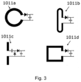
- the array (101) of microwave energy harvesting cells (1011) is an array of flat antennas with microwave rectifiers and capacitors as variants (1011a, 1011b, 1011c, 1011d) presented in Fig. 3 .
- Each harvesting cell can be a split ring (1011a), loop (1011b), dipole (1011c), split rectangular (1011d), etc., or another 2D antenna configuration.
- a flat antenna is connected to a rectifier and capacitor as shown in Fig. 3 .
- the data hub (300), operating on standard frequencies above 1 GHz can communicate with distributed data nodes of special segments (100) installed in conveyor band in the location of few meters.
- the microwave energy is radiated from the data hub (300), is received by the harvesting cells (1011), rectified by microwave diodes, and stored in the capacitors of the cells.
- the DC energy stored in the capacitors of the cells (1011) is added up and delivered to the energy storage and monitoring unit (104).
- the data hub (300) is located as close as possible to the harvesting array (101). Depending on the directivity of the data hub (300) energy harvesting can be effectively provided at a distance of a few meters. Because the voltage of energy stored in the harvesting array (101) depends on the power density of microwave radiation and working conditions, the energy storage monitoring unit (104) is applied to stabilize the DC voltage and ensure the best efficiency of microwave energy conversion and storage.
- the harvested energy storing and monitoring unit (104) comprises a maximum power point tracking (MPPT) device (1041), a voltage booster with stabilizer (1042), and a supercapacitor (1043), which collects and stores the overall energy from harvesting cells from the harvesting array (101).
- MPPT maximum power point tracking
- the energy stored in the supercapacitor (1043) of the storage monitor unit (104) supplies power to the electronic circuitry of sensors (102) and the data processing node (103).
- the data processing node (103) is a wireless transceiver that collects signals from the sensors (102), processes the data, and transmits it to the data hub (300).
- the data collection hub (300) is a device such as a Wi-Fi router, a Zig-Bee, a Bluetooth, or other wireless communication transceiver operating on 2.45 GHz, 5 GHz, etc., or other microwave frequencies.
- the data hub (300) performs a twofold task: first, it communicates with the data node (103); second, it supports the power supply for electronic circuitry installed in the conveyor's energy harvesting segment (100), as shown in Fig. 2 .
- the abovementioned configuration of the conveyor band (200) surface monitoring system provides high protection from harsh environmental conditions and can autonomously and reliably operate without regular service.
- the production conveyor condition monitoring system which is proposed in the invention, ensures improved productivity of the conveyer, reduces the costs of service, and improves the reliability of the production process.
Landscapes
- Engineering & Computer Science (AREA)
- Computer Networks & Wireless Communication (AREA)
- Power Engineering (AREA)
- Control Of Conveyors (AREA)
Abstract
Description
- The invention relates to a product conveyor band surface condition monitoring system for uninterruptable conveyor band operation in a harsh environment.
- A wide variety of sensors are utilized to monitor and control state of a conveyor surface. Especially, condition of a conveyor surface should meet specific hygienic norms and technological requirements set for the food industry. Warmed chemical detergents are usually used for the conveyor's surface washing, and thereafter they are rinsed on the go. On the one hand, penetration of acidic and alkaline substrates from the conveyor's surface to the products is not tolerated. On the other hand, electronic equipment for monitoring conveyor conditions should be protected from the harsh environment.
- Wireless communication is commonly used to transfer data from moving sensors to data collection hubs. The power supply of sensors using changeable or rechargeable batteries is generally not acceptable since changing batteries or their charging calls for interruption of technological processes, losses in production, and additional time consumption.
- Energy harvesting, energy storing, and supplying to conveyor surface condition monitoring system integrated into a moving conveyor band allows avoiding the application of changeable batteries and improves the productivity of a conveyor. Different energy harvesting systems are proposed for a variety of applications like systems with wireless sensors, room condition monitoring systems, and different energy harvesting methods in conveyors.
- US patent application, publication No.:
US20180139517 discloses a building's wireless sensor system, where temperature, humidity, etc. sensors distributed in different places of the building are charged by radio frequency (RF) energy harvesters, which accumulate energy of electromagnetic field transmitted from data hubs emitting RF waves. The main disadvantage of the disclosed system is that the proposed RF energy harvesters are not suitable for moving applications. - International patent application, publication No.:
WO2015019106 , discloses an RF energy harvester for stationary systems, where a used rectenna is a 3D structure. The thickness of the rectenna is λ/4.8, where λ is the wavelength of the RF source in free space. In the case of standard Wi-Fi working at 2.45 GHz frequency, λ/4.8 is 25 mm. The proposed 3D antenna cannot be applied as an energy harvester for electronics embedded in a moving conveyor band. - European patent application, publication No.:
EP2643244 , discloses energy-harvesting conveyor belts and methods for power supply by harvesting ambient RF energy for electronic units installed in such conveyor belts. Disclosed transmitting antennas are coils of transmitters closely located to a conveyor belt, where the harvester receiver coils are embedded in a conveyor band. Such technology is widely used in RFID applications working at close distances and low RF carrier frequencies. The disclosed method and system limit dimensions of products that can be transported by a conveyor band and are not suitable to operate at microwave frequencies when the receiver and emitter are substantially apart from each other. - The present invention is dedicated to overcoming the above shortcomings and producing further advantages over prior art.
- According to the invention, the conveyor band surface condition monitoring system comprises at least one energy harvesting segment of a segmented conveyor band comprising integrated electronics and various sensors, integrated into at least one segment of the conveyor band. In another instance, the sensors may be attached to the surface of the segment of the segmented conveyor band. The system further comprises a wireless data hub. The data hub is such that operates on standard frequencies above 1 GHz and communicates with distributed data nodes of the energy harvesting segments.
- The integrated electronics of the energy harvesting segment comprises an array of microwave energy harvesting cells, an energy storage monitoring unit, and a data processing node. The array of microwave energy harvesting cells is an array of flat antennas with microwave rectifiers and capacitors. Depending on the type and destination of the sensors at least one sensor is either encapsulated into the body of the energy harvesting segment or mounted on its surface facing the wireless data hub when the harvesting segment is moving at the upper part of the conveyor band between the wireless data hub and lower part of a conveyor band.
- The various sensors for example are sensors used for control of dosing of detergents and rinsing liquids, temperature, humidity, and other parameters of the surface of the segment of the conveyor band. In the present invention, the data hub plays a twofold role. On the one hand, it provides communication with nodes integrated into the conveyor band, and, on the other hand, radiates microwave energy, serving as an energy source for sensors and electronic circuitry encapsulated into the energy harvesting segment of the segmented conveyor band. The conveyor band surface condition monitoring system provides permanent control of the conveyor band's surface condition and avoids the interruptions of technological processes required for battery replacements or recharging.
- Features of the invention believed to be novel and inventive are set forth with particularity in the appended claims. The invention itself, however, may be best understood by reference to the following detailed description of the invention, which describes exemplary embodiments, given in non-restrictive examples, of the invention, taken in conjunction with the accompanying drawings, in which:
-
Fig. 1 shows segmented conveyor band condition monitoring system. -
Fig. 2 shows energy harvesting segment of the segmented conveyor band comprising sensors and a wireless data node. -
Fig. 3 shows examples of RF energy harvesting cells: a) split ring, b) loop, c) dipole, d) split rectangular. - Preferred embodiments of the invention will be described herein below with reference to the drawings. Each figure contains the same numbering for the same or equivalent element.
- It should be understood that numerous specific details are presented in order to provide a complete and comprehensible description of the invention's embodiment. However, the person skilled in the art will understand that the embodiment examples do not limit the application of the invention, which can be implemented without these specific instructions. Well-known methods, procedures, and components have not been described in detail for the embodiment to avoid being misleading. Furthermore, this description should not be considered to constrain the invention to the given embodiment examples but only as one of the possible implementations of the invention.
- The invention is a conveyor band surface condition monitoring system, as shown in
Fig. 1 , comprising an energy harvesting segment (100) of a segmented conveyor band (200) and a wireless data hub (300). The energy harvesting segment (100), as shown inFig. 2 , comprises integrated electronics comprising an array (101) of microwave energy harvesting cells (1011), an energy storage monitoring unit (104), and a data processing node (103) all being encapsulated in the energy harvesting segment (100). Depending on type and destination, at least one sensor (102) is either encapsulated into the body of the energy harvesting segment (100) or mounted on its surface facing the data hub (300) when the energy harvesting segment (100) is moving at the upper part of the conveyor band (200) between the wireless data hub (300) and lower part of the conveyor band (200). - The array (101) of microwave energy harvesting cells (1011) is an array of flat antennas with microwave rectifiers and capacitors as variants (1011a, 1011b, 1011c, 1011d) presented in
Fig. 3 . Each harvesting cell can be a split ring (1011a), loop (1011b), dipole (1011c), split rectangular (1011d), etc., or another 2D antenna configuration. A flat antenna is connected to a rectifier and capacitor as shown inFig. 3 . - The data hub (300), operating on standard frequencies above 1 GHz can communicate with distributed data nodes of special segments (100) installed in conveyor band in the location of few meters.
- The microwave energy is radiated from the data hub (300), is received by the harvesting cells (1011), rectified by microwave diodes, and stored in the capacitors of the cells. The DC energy stored in the capacitors of the cells (1011) is added up and delivered to the energy storage and monitoring unit (104). To increase the microwave radiation power density and effectiveness of microwave energy harvesting, the data hub (300) is located as close as possible to the harvesting array (101). Depending on the directivity of the data hub (300) energy harvesting can be effectively provided at a distance of a few meters. Because the voltage of energy stored in the harvesting array (101) depends on the power density of microwave radiation and working conditions, the energy storage monitoring unit (104) is applied to stabilize the DC voltage and ensure the best efficiency of microwave energy conversion and storage. The harvested energy storing and monitoring unit (104) comprises a maximum power point tracking (MPPT) device (1041), a voltage booster with stabilizer (1042), and a supercapacitor (1043), which collects and stores the overall energy from harvesting cells from the harvesting array (101). The energy stored in the supercapacitor (1043) of the storage monitor unit (104) supplies power to the electronic circuitry of sensors (102) and the data processing node (103). The data processing node (103) is a wireless transceiver that collects signals from the sensors (102), processes the data, and transmits it to the data hub (300).
- The data collection hub (300) is a device such as a Wi-Fi router, a Zig-Bee, a Bluetooth, or other wireless communication transceiver operating on 2.45 GHz, 5 GHz, etc., or other microwave frequencies. The data hub (300) performs a twofold task: first, it communicates with the data node (103); second, it supports the power supply for electronic circuitry installed in the conveyor's energy harvesting segment (100), as shown in
Fig. 2 . - The abovementioned configuration of the conveyor band (200) surface monitoring system provides high protection from harsh environmental conditions and can autonomously and reliably operate without regular service.
- The production conveyor condition monitoring system, which is proposed in the invention, ensures improved productivity of the conveyer, reduces the costs of service, and improves the reliability of the production process.
- Although numerous characteristics and advantages, together with structural details and features, have been listed in the present description of the invention, the description is provided as an example of its fulfilment. Without departing from the principles of the invention, there may be changes in the details, especially in the form, size, and layout, in accordance with the most widely understood meanings of the concepts and definitions used in the claims.
Claims (7)
- A conveyor band surface condition monitoring system comprising a microwave frequency energy emitter and a microwave frequency energy receiver characterised in that the microwave frequency energy emitter is a data hub (300) and the microwave frequency energy receiver is a conveyor band (200) energy harvesting segment (100) comprising integrated electronics comprising an array (101) of microwave energy harvesting cells (1011), an energy storage monitoring unit (104), a data processing node (103) and at least one sensor (102).
- The conveyor band surface condition monitoring system according to claim 1, where the array (101) of microwave energy harvesting cells (1011) is an array of flat antennas (1011a, 1011b, 1011c, 1011d) comprising microwave rectifiers and capacitors.
- The conveyor band surface condition monitoring system according to claim 2, where each harvesting cell is such as a split ring (1011a), or a loop (1011b), or a dipole (1011c), or a split rectangular (1011d).
- The conveyor band surface condition monitoring system according to any one of the previous claims, where the energy storage monitoring unit (104) comprises a maximum power point tracking (MPPT) device (1041), a voltage booster with stabilizer (1042), and a supercapacitor (1043).
- The conveyor band surface condition monitoring system according to any one of the previous claims, where the array (101) of microwave energy harvesting cells (1011), the energy storage monitoring unit (104), the data processing node (103), and the at least one sensor (102) are encapsulated in the conveyor band (200) energy harvesting segment (100).
- The conveyor band surface condition monitoring system according to any one of claims 1-4, where the array (101) of microwave energy harvesting cells (1011), the energy storage monitoring unit (104), the data processing node (103), and the at least one sensor (102) are disposed on the surface energy harvesting segment (100) of the conveyor band (200).
- A method for monitoring conveyor band surface condition using a system of any one of claims 1 - 6, characterised in that microwave energy radiated from a data hub (300) and harvested by harvesting cells (1011) is rectified by microwave diodes and stored in capacitors of the harvesting cells (1011), where DC energy stored in the capacitors of the cells (1011) is added up and delivered to energy storage and monitoring unit (104) for stabilizing the DC voltage.
Priority Applications (1)
| Application Number | Priority Date | Filing Date | Title |
|---|---|---|---|
| EP23205086.4A EP4546610B1 (en) | 2023-10-23 | 2023-10-23 | Conveyor band surface condition monitoring system |
Applications Claiming Priority (1)
| Application Number | Priority Date | Filing Date | Title |
|---|---|---|---|
| EP23205086.4A EP4546610B1 (en) | 2023-10-23 | 2023-10-23 | Conveyor band surface condition monitoring system |
Publications (3)
| Publication Number | Publication Date |
|---|---|
| EP4546610A1 true EP4546610A1 (en) | 2025-04-30 |
| EP4546610C0 EP4546610C0 (en) | 2025-08-06 |
| EP4546610B1 EP4546610B1 (en) | 2025-08-06 |
Family
ID=88511414
Family Applications (1)
| Application Number | Title | Priority Date | Filing Date |
|---|---|---|---|
| EP23205086.4A Active EP4546610B1 (en) | 2023-10-23 | 2023-10-23 | Conveyor band surface condition monitoring system |
Country Status (1)
| Country | Link |
|---|---|
| EP (1) | EP4546610B1 (en) |
Citations (6)
| Publication number | Priority date | Publication date | Assignee | Title |
|---|---|---|---|---|
| WO2012071198A2 (en) * | 2010-11-22 | 2012-05-31 | Laitram, L.L.C. | Energy-harvesting conveyor belts and methods |
| WO2015019106A2 (en) | 2013-08-09 | 2015-02-12 | Drayson Wireless Limited | Rf energy harvester |
| US20160103084A1 (en) * | 2014-04-15 | 2016-04-14 | Laitram, L.L.C. | Conveyor belt measuring system |
| US20180139517A1 (en) | 2016-11-15 | 2018-05-17 | Palo Alto Research Center Incorporated | Wireless building sensor system |
| US20180241251A1 (en) * | 2015-09-18 | 2018-08-23 | Fuji Machine Mfg. Co., Ltd. | Non-contact power feeding device |
| US20220069754A1 (en) * | 2020-08-28 | 2022-03-03 | Schneider Electric Industries Sas | Linear motor system and method for operating |
-
2023
- 2023-10-23 EP EP23205086.4A patent/EP4546610B1/en active Active
Patent Citations (7)
| Publication number | Priority date | Publication date | Assignee | Title |
|---|---|---|---|---|
| WO2012071198A2 (en) * | 2010-11-22 | 2012-05-31 | Laitram, L.L.C. | Energy-harvesting conveyor belts and methods |
| EP2643244A2 (en) | 2010-11-22 | 2013-10-02 | Laitram, L.L.C. | Energy-harvesting conveyor belts and methods |
| WO2015019106A2 (en) | 2013-08-09 | 2015-02-12 | Drayson Wireless Limited | Rf energy harvester |
| US20160103084A1 (en) * | 2014-04-15 | 2016-04-14 | Laitram, L.L.C. | Conveyor belt measuring system |
| US20180241251A1 (en) * | 2015-09-18 | 2018-08-23 | Fuji Machine Mfg. Co., Ltd. | Non-contact power feeding device |
| US20180139517A1 (en) | 2016-11-15 | 2018-05-17 | Palo Alto Research Center Incorporated | Wireless building sensor system |
| US20220069754A1 (en) * | 2020-08-28 | 2022-03-03 | Schneider Electric Industries Sas | Linear motor system and method for operating |
Also Published As
| Publication number | Publication date |
|---|---|
| EP4546610C0 (en) | 2025-08-06 |
| EP4546610B1 (en) | 2025-08-06 |
Similar Documents
| Publication | Publication Date | Title |
|---|---|---|
| US11011942B2 (en) | Flat antennas having two or more resonant frequencies for use in wireless power transmission systems | |
| US12199336B2 (en) | Multi-band energy harvesting system | |
| US10714984B2 (en) | Systems, methods, and devices for using a battery as an antenna for receiving wirelessly delivered power from radio frequency power waves | |
| US11539243B2 (en) | Systems and methods for miniaturized antenna for wireless power transmissions | |
| EP1513685B1 (en) | Radio frequency identification tag with thin-film battery for antenna | |
| US7925308B2 (en) | Radio-frequency (RF) power portal | |
| EP3864737B1 (en) | Dynamic rectifier circuits with multiple-order timescale feedback controls | |
| US20180198199A1 (en) | Devices And Methods For Reducing Mutual Coupling Effects In Wireless Power Transmission Systems | |
| US20180269570A1 (en) | Surface Mount Dielectric Antennas for Wireless Power Transmitters | |
| WO2023009464A2 (en) | Hybrid rfid and wireless communication system for tracking of assets and people and method thereof | |
| KR101528632B1 (en) | Dual-band active RFID systems for the smart management | |
| WO2007019104A2 (en) | Harvesting ambient radio frequency electromagnetic energy for powering wireless electronic devices, sensors and sensor networks and applications thereof | |
| WO2008118591A2 (en) | Methods and systems of tagging objects and reading tags coupled to objects | |
| KR20100061664A (en) | Automatic antenna tuner system for rfid | |
| Chen et al. | Q-charge: A quadcopter-based wireless charging platform for large-scale sensing applications | |
| WO2008088984A2 (en) | Transponder networks and transponder systems employing a touch probe reader device | |
| EP4546610A1 (en) | Conveyor band surface condition monitoring system | |
| US7893816B1 (en) | High sensitivity radio frequency identification tag | |
| Sangare et al. | RF energy harvesting networks: Existing techniques and hardware technology | |
| CN108334923B (en) | Electronic tag | |
| JP2008105855A (en) | Article management method | |
| KR20080113626A (en) | Wireless tag for aviation WD Pallet | |
| KR101602637B1 (en) | Article management method and article management system | |
| US20200296549A1 (en) | Moving body state identification system and method | |
| Yousof Naderi et al. | Next-Generation Software-Defined Wireless Charging System |
Legal Events
| Date | Code | Title | Description |
|---|---|---|---|
| PUAI | Public reference made under article 153(3) epc to a published international application that has entered the european phase |
Free format text: ORIGINAL CODE: 0009012 |
|
| STAA | Information on the status of an ep patent application or granted ep patent |
Free format text: STATUS: REQUEST FOR EXAMINATION WAS MADE |
|
| 17P | Request for examination filed |
Effective date: 20240806 |
|
| AK | Designated contracting states |
Kind code of ref document: A1 Designated state(s): AL AT BE BG CH CY CZ DE DK EE ES FI FR GB GR HR HU IE IS IT LI LT LU LV MC ME MK MT NL NO PL PT RO RS SE SI SK SM TR |
|
| GRAP | Despatch of communication of intention to grant a patent |
Free format text: ORIGINAL CODE: EPIDOSNIGR1 |
|
| STAA | Information on the status of an ep patent application or granted ep patent |
Free format text: STATUS: GRANT OF PATENT IS INTENDED |
|
| GRAS | Grant fee paid |
Free format text: ORIGINAL CODE: EPIDOSNIGR3 |
|
| GRAA | (expected) grant |
Free format text: ORIGINAL CODE: 0009210 |
|
| STAA | Information on the status of an ep patent application or granted ep patent |
Free format text: STATUS: THE PATENT HAS BEEN GRANTED |
|
| INTG | Intention to grant announced |
Effective date: 20250606 |
|
| AK | Designated contracting states |
Kind code of ref document: B1 Designated state(s): AL AT BE BG CH CY CZ DE DK EE ES FI FR GB GR HR HU IE IS IT LI LT LU LV MC ME MK MT NL NO PL PT RO RS SE SI SK SM TR |
|
| REG | Reference to a national code |
Ref country code: GB Ref legal event code: FG4D |
|
| REG | Reference to a national code |
Ref country code: CH Ref legal event code: EP |
|
| REG | Reference to a national code |
Ref country code: IE Ref legal event code: FG4D |
|
| REG | Reference to a national code |
Ref country code: DE Ref legal event code: R096 Ref document number: 602023005438 Country of ref document: DE |
|
| U01 | Request for unitary effect filed |
Effective date: 20250825 |
|
| U07 | Unitary effect registered |
Designated state(s): AT BE BG DE DK EE FI FR IT LT LU LV MT NL PT RO SE SI Effective date: 20250905 |
|
| U20 | Renewal fee for the european patent with unitary effect paid |
Year of fee payment: 3 Effective date: 20251020 |
|
| PG25 | Lapsed in a contracting state [announced via postgrant information from national office to epo] |
Ref country code: IS Free format text: LAPSE BECAUSE OF FAILURE TO SUBMIT A TRANSLATION OF THE DESCRIPTION OR TO PAY THE FEE WITHIN THE PRESCRIBED TIME-LIMIT Effective date: 20251206 |
|
| PG25 | Lapsed in a contracting state [announced via postgrant information from national office to epo] |
Ref country code: NO Free format text: LAPSE BECAUSE OF FAILURE TO SUBMIT A TRANSLATION OF THE DESCRIPTION OR TO PAY THE FEE WITHIN THE PRESCRIBED TIME-LIMIT Effective date: 20251106 |
|
| PG25 | Lapsed in a contracting state [announced via postgrant information from national office to epo] |
Ref country code: HR Free format text: LAPSE BECAUSE OF FAILURE TO SUBMIT A TRANSLATION OF THE DESCRIPTION OR TO PAY THE FEE WITHIN THE PRESCRIBED TIME-LIMIT Effective date: 20250806 |
|
| PG25 | Lapsed in a contracting state [announced via postgrant information from national office to epo] |
Ref country code: GR Free format text: LAPSE BECAUSE OF FAILURE TO SUBMIT A TRANSLATION OF THE DESCRIPTION OR TO PAY THE FEE WITHIN THE PRESCRIBED TIME-LIMIT Effective date: 20251107 |
|
| PG25 | Lapsed in a contracting state [announced via postgrant information from national office to epo] |
Ref country code: PL Free format text: LAPSE BECAUSE OF FAILURE TO SUBMIT A TRANSLATION OF THE DESCRIPTION OR TO PAY THE FEE WITHIN THE PRESCRIBED TIME-LIMIT Effective date: 20250806 |
|
| PG25 | Lapsed in a contracting state [announced via postgrant information from national office to epo] |
Ref country code: RS Free format text: LAPSE BECAUSE OF FAILURE TO SUBMIT A TRANSLATION OF THE DESCRIPTION OR TO PAY THE FEE WITHIN THE PRESCRIBED TIME-LIMIT Effective date: 20251106 |
|
| PG25 | Lapsed in a contracting state [announced via postgrant information from national office to epo] |
Ref country code: ES Free format text: LAPSE BECAUSE OF FAILURE TO SUBMIT A TRANSLATION OF THE DESCRIPTION OR TO PAY THE FEE WITHIN THE PRESCRIBED TIME-LIMIT Effective date: 20250806 |
|
| PG25 | Lapsed in a contracting state [announced via postgrant information from national office to epo] |
Ref country code: SM Free format text: LAPSE BECAUSE OF FAILURE TO SUBMIT A TRANSLATION OF THE DESCRIPTION OR TO PAY THE FEE WITHIN THE PRESCRIBED TIME-LIMIT Effective date: 20250806 |
|
| PG25 | Lapsed in a contracting state [announced via postgrant information from national office to epo] |
Ref country code: CZ Free format text: LAPSE BECAUSE OF FAILURE TO SUBMIT A TRANSLATION OF THE DESCRIPTION OR TO PAY THE FEE WITHIN THE PRESCRIBED TIME-LIMIT Effective date: 20250806 |
|
| PG25 | Lapsed in a contracting state [announced via postgrant information from national office to epo] |
Ref country code: SK Free format text: LAPSE BECAUSE OF FAILURE TO SUBMIT A TRANSLATION OF THE DESCRIPTION OR TO PAY THE FEE WITHIN THE PRESCRIBED TIME-LIMIT Effective date: 20250806 |