EP4546558A1 - A gnss/sdars antenna system - Google Patents
A gnss/sdars antenna system Download PDFInfo
- Publication number
- EP4546558A1 EP4546558A1 EP23206473.3A EP23206473A EP4546558A1 EP 4546558 A1 EP4546558 A1 EP 4546558A1 EP 23206473 A EP23206473 A EP 23206473A EP 4546558 A1 EP4546558 A1 EP 4546558A1
- Authority
- EP
- European Patent Office
- Prior art keywords
- antenna
- antenna system
- tcu
- gnss
- plastic substrate
- Prior art date
- Legal status (The legal status is an assumption and is not a legal conclusion. Google has not performed a legal analysis and makes no representation as to the accuracy of the status listed.)
- Pending
Links
Images

Classifications
-
- H—ELECTRICITY
- H01—ELECTRIC ELEMENTS
- H01Q—ANTENNAS, i.e. RADIO AERIALS
- H01Q1/00—Details of, or arrangements associated with, antennas
- H01Q1/27—Adaptation for use in or on movable bodies
- H01Q1/32—Adaptation for use in or on road or rail vehicles
- H01Q1/3208—Adaptation for use in or on road or rail vehicles characterised by the application wherein the antenna is used
- H01Q1/3233—Adaptation for use in or on road or rail vehicles characterised by the application wherein the antenna is used particular used as part of a sensor or in a security system, e.g. for automotive radar, navigation systems
-
- H—ELECTRICITY
- H01—ELECTRIC ELEMENTS
- H01Q—ANTENNAS, i.e. RADIO AERIALS
- H01Q1/00—Details of, or arrangements associated with, antennas
- H01Q1/12—Supports; Mounting means
- H01Q1/1207—Supports; Mounting means for fastening a rigid aerial element
- H01Q1/1221—Supports; Mounting means for fastening a rigid aerial element onto a wall
-
- H—ELECTRICITY
- H01—ELECTRIC ELEMENTS
- H01Q—ANTENNAS, i.e. RADIO AERIALS
- H01Q1/00—Details of, or arrangements associated with, antennas
- H01Q1/27—Adaptation for use in or on movable bodies
- H01Q1/32—Adaptation for use in or on road or rail vehicles
- H01Q1/325—Adaptation for use in or on road or rail vehicles characterised by the location of the antenna on the vehicle
- H01Q1/3275—Adaptation for use in or on road or rail vehicles characterised by the location of the antenna on the vehicle mounted on a horizontal surface of the vehicle, e.g. on roof, hood, trunk
-
- H—ELECTRICITY
- H01—ELECTRIC ELEMENTS
- H01Q—ANTENNAS, i.e. RADIO AERIALS
- H01Q21/00—Antenna arrays or systems
- H01Q21/28—Combinations of substantially independent non-interacting antenna units or systems
-
- H—ELECTRICITY
- H01—ELECTRIC ELEMENTS
- H01Q—ANTENNAS, i.e. RADIO AERIALS
- H01Q5/00—Arrangements for simultaneous operation of antennas on two or more different wavebands, e.g. dual-band or multi-band arrangements
- H01Q5/30—Arrangements for providing operation on different wavebands
- H01Q5/307—Individual or coupled radiating elements, each element being fed in an unspecified way
-
- H—ELECTRICITY
- H01—ELECTRIC ELEMENTS
- H01Q—ANTENNAS, i.e. RADIO AERIALS
- H01Q9/00—Electrically-short antennas having dimensions not more than twice the operating wavelength and consisting of conductive active radiating elements
- H01Q9/04—Resonant antennas
- H01Q9/0407—Substantially flat resonant element parallel to ground plane, e.g. patch antenna
- H01Q9/0414—Substantially flat resonant element parallel to ground plane, e.g. patch antenna in a stacked or folded configuration
-
- H—ELECTRICITY
- H01—ELECTRIC ELEMENTS
- H01Q—ANTENNAS, i.e. RADIO AERIALS
- H01Q9/00—Electrically-short antennas having dimensions not more than twice the operating wavelength and consisting of conductive active radiating elements
- H01Q9/04—Resonant antennas
- H01Q9/0407—Substantially flat resonant element parallel to ground plane, e.g. patch antenna
- H01Q9/0428—Substantially flat resonant element parallel to ground plane, e.g. patch antenna radiating a circular polarised wave
Definitions
- the present invention relates to the field of antennas, and more specifically to an antenna system of a vehicle telematic control unit. It is also related to a TCU comprising said antenna system, and a vehicle comprising said TCU.
- Multiband antenna systems are also commonly used in the automotive industry. Such an antenna system includes a small number of antennas to cover and operate at multiple frequency ranges and/or for redundancy reasons.
- An antenna system can be installed on the roof surface of a vehicle to let the antennas have an unobstructed view overhead.
- This antenna system is generally connected to one or more electronic devices (e.g., a cellular phone) inside the passenger compartment of the vehicle, such that the antenna system is operable for transmitting and/or receiving signals to/from the electronic device inside the vehicle.
- electronic devices e.g., a cellular phone
- TCU Telematics Control Unit
- the role of the Telematics Control Unit (TCU) in a car is to control wireless tracking, diagnostics and communication to and from the vehicle using such an antenna system.
- TCU Telematics Control Unit
- a TCU is embedded onboard on a vehicle.
- TCUs are becoming more and more limited in space so as to satisfy vehicle design requirements.
- Electronic vehicle components for the TCU therefore need to become as small as possible to satisfy the vehicle manufacturing design requirements and fit the necessary amount of components within the TCU.
- an antenna system of a vehicle telematic control unit comprising a global navigation satellite system (GNSS) dual antenna, and a satellite digital audio radio service (SDARS) antenna.
- GNSS global navigation satellite system
- SDARS satellite digital audio radio service
- the antenna system may comprise one or more of the following features:
- a TCU comprising the antenna system, the antenna system being configured to be mounted on a main PCB of the TCU.
- a TCU comprising the antenna system, the antenna system being configured to form a part of a housing of the TCU.
- a TCU comprising the antenna system, and an antenna support frame mounted on a main PCB of the TCU.
- the TCU further comprises an elevated PCB mounted on the antennas support frame.
- the antenna system is configured to be mounted on the elevated PCB.
- the antenna support frame may be made of metal.
- a vehicle comprising a TCU according to any one of the above.
- the antenna system comprises a global navigation satellite system (GNSS) dual antenna, and a satellite digital audio radio service (SDARS) antenna.
- GNSS global navigation satellite system
- SDARS satellite digital audio radio service
- the GNSS dual antenna and the SDARS antenna are mounted on a first plastic substrate. This means that the first plastic surface is in physical contact with the GNSS antenna and SDARS antenna.
- Such an antenna system constitutes a combined GNSS/SDARS antenna system to be used in the TCU of a vehicle, in particular a terrestrial vehicle such as an automobile, a motorcycle, or a truck.
- This constitutes an improved solution, as the GNSS antenna and the SDARS antenna are placed (i.e., mounted) on a plastic substrate.
- a plastic substrate Compared to ceramic substrates which are widely used in the field of antennas, such a plastic substrate provides more flexibility to a designer to set antenna's geometry.
- any antenna herein is an interface between radio waves propagating through space and electric currents moving in metal conductors, used with a transmitter or receiver.
- a radio transmitter may supply an electric current to the terminals of the antenna, and the antenna may radiate the energy from the current as electromagnetic waves (radio waves).
- the antenna may intercept some of the power of a radio wave in order to produce an electric current at its terminals, that is applied to a receiver to be amplified.
- GNSS antennas and SDARS antennas only have receiver functionality.
- TCU comprising an antenna system as described herein.
- a TCU in the automobile industry such as the TCU herein is an embedded system on board of a vehicle that wirelessly connects the vehicle to cloud services or other vehicles over a cellular network.
- the TCU collects telemetry data from the vehicle, such as position, speed, engine data, connectivity quality, etc., from various sub-systems over data and control busses.
- the TCU has a main printed circuit board (PCB) on which a plurality of elements, antennas, sensors, controllers, or busses may be mounted.
- a TCU comprising the antenna system is particularly suitable for being installed inside a vehicle, such as a car.
- the TCU may be installed inside the dashboard or under the roof of the car. Installing the TCU in such an area can therefore provide for additional useable space inside the dashboard or under the roof for other components, such as other components for placing upon the PCB.
- a PCB such the PCB herein is a medium used to connect electronic components to one another in a controlled manner.
- the PCB is in the form of a laminated sandwich structure of conductive and insulating layers: each of the conductive layers is designed with a pattern of traces, planes and/or other features, etched from one or more sheet layers of copper laminated onto and/or between sheet layers of a non-conductive substrate.
- Electrical components may be fixed to conductive pads on the outer layers in the shape designed to accept the component's terminals, generally by means of soldering, to both electrically connect and mechanically fasten them to the PCB. Additionally or alternatively, connections may be made using vias (plated-through holes that allow interconnections between layers).
- Dimensions of the antenna system may be according to dimensions of a TCU in which the antenna system is to be mounted.
- the dimensions of the TCU may be small enough to be installable inside a vehicle, for example inside the dashboard, under the roof, or inside the body.
- the antenna system may have a height between 5 and 7mm, a width between 100 and 150mm, and a depth between 50 and 75mm.
- the depth and the width are the lengths of the antenna system on a plane parallel to the plane of the TCU (e.g., an x-y plane).
- the height, or equivalently thickness is a length of the antenna system orthogonal to said plane (e.g., along a z-axis).
- Said height may be preferably about 6mm.
- Said width may be preferably between 110 and 130mm, and more preferably about 120mm.
- Said depth may be preferably between 65 and 70mm, and more preferably about 68mm. Such dimensions make the antenna system perfectly employable in modern TCUs for vehicles.
- both of the GNSS antenna and the SDARS antenna of the antenna system are positioned aside each other and on a same plane. This improves the performance of each of the antennas while helping to reduce of the thickness of the antenna system (and thereby the final TCU).
- being positioned aside each other it is meant that said antennas are not positioned (even partially) on top of each other (i.e., no overlap), and their distance is significantly small compared to their dimensions (e.g., below 5 percent or below 2 percent, for example relative to their diameter, i.e. the longest straight segment joining two points of each respective component).
- being on a same plane it is meant that said antennas reside on a same plane upon some dents or protrusions over said plane. For example, a significant amount of surface areas of said antennas (e.g., above 90 percent or 95 percent) reside on said plane.
- said plane may be the same plane as of the first plastic substrate.
- the first plastic substrate has a plurality of positional and a plurality of dimensional parameters.
- Said positional parameters may define a position of the first plastic substrate with respect to the TCU.
- Said dimensional parameters may define a shape/geometry of said first plastic substrate.
- said positional parameters and said dimensional parameters may be configured to optimize a performance metric of the antenna system.
- a performance metric of the antenna system it is meant a metric representing a combined performance of the GNSS antenna and of the SDARS antenna.
- Such a performance metric may be defined as a function of a first performance metric for the GNSS antenna and a second performance metric for the SDARS antenna.
- the function may be a summation, a maximum or a minimum.
- the first performance metric and the second performance metric may be the same, though evaluated on a different antenna.
- a performance metric may be a metric known in the field, for example, any of: an efficiency, an average gain in zenith (i.e., the highest elevation angle), or an average gain in different (i.e., a plurality of) elevation angles.
- an “elevation angle” it is meant the angle between the horizontal plane and the line of sight.
- being configured to optimize a performance metric it is meant that said parameters (positional and/or dimensional) are the result of an optimization program in which the positional parameters and/or dimensional parameters of the first substrate are the free variables and said performance metric is an objective function of said optimization program.
- the optimization program may further consider one or more other objective functions and/or optimization constraints.
- the GNSS dual antenna may comprise a first metal part and a second metal part.
- the GNSS dual antenna may further comprise a second plastic substrate.
- the first metal part, the second metal part, and the second plastic substrate may be arranged on top of each other.
- the first metal part and the second metal part may sandwich the second plastic substrate.
- the second plastic substrate may be between the first metal part and the second metal part.
- the GNSS dual antenna may operate at two frequency bands L1 and L5.
- a microstrip patch antenna with a stacked structure and a single feed may be used for the purpose of dual-band operation.
- the GNSS may have two metal parts (i.e., the first metal part and the second metal part) in order to cover both L1 and L5 bands.
- the metal part for the L5 (see 131 in FIG. 1 ) is bigger than the metal part for L1 (see 132 in FIG. 1 ).
- the metal part for L5 is beneath the part for L1 and used also as a reflector for L1 metal part.
- a single feed may be used to excite the L1 metal part directly and the L5 part is parasitically fed by coupling to the L1 part.
- the second plastic substrate (see 104 in FIG. 1 ) is to separate the GNSS drive element (which corresponds to L1 band) and the GNSS parasitic element (which corresponds to L5 band).
- the GNSS antenna metal element sizes, shapes and the placement of the feeding point and the position and size of the slots are designed to ensure the RHCP (right hand circular polarization) and to optimize the performance both for the average gain in zenith as well as lower elevation angles.
- the SDARS antenna may cover the Sirius XM frequency band, i.e., 2.3325 GHz - 2.345 GHz.
- a single feed may be used to excite the SDARS antenna.
- the SDARS antenna metal element sizes, shapes and the placement of the feeding point and position and size of the slots are designed to ensure the LHCP (left hand circular polarization) and to optimize the performance both for the average gain in zenith as well as low elevation angles.
- the first plastic substrate and/or the second plastic substrate are made of Acrylonitrile Butadiene Styrene (ABS).
- ABS Acrylonitrile Butadiene Styrene
- An antenna system as discussed above may be mounted in different configurations in a respective TCU.
- the first plastic substrate is configured to be mounted on a main PCB of the TCU. In other words, there is no gap between the first plastic substrate and the main PCB. Such configuration helps reducing the thickness of the TCU.
- the first plastic surface forms a part of a housing of the TCU.
- the plastic surface may form part of the top housing of the TCU and be mounted over the main PCB when the top housing is closed.
- the housing of the TCU may be made of plastic.
- the gap may be up to 5 mm, preferably between 2mm and 3mm. The presence of such a gap creates a space between the first plastic substrate and the main PCB.
- the TCU may comprise other modules chipset in said space, for example network access devices (NADs). This provides a solution in which more chipsets can be integrated in a TCU of a given dimension.
- NADs network access devices
- the second configuration provides a TCU comprising an antenna system as discussed above.
- the antenna system is configured to form a part of a housing of the TCU.
- the antenna system may be configured to be mounted on an elevated PCB.
- an elevated PCB it is meant a PCB other than the main PCB of the TCU and which is positioned at a distance (e.g., a constant distance) with respect to the main PCB, i.e., elevated.
- Such an elevated PCB may be configured to be mounted on a support frame.
- the support frame may be mounted on the main PCB.
- the support frame may be of a rectangular shape and/or of a constant thickness.
- the support frame may be made of plastic or metal, preferably metal.
- a metal support frame herein may be made of aluminum, copper, brass, nickel, silver, steel (for example stainless steel), and/or tin.
- a metal support frame is able to provide a solid ground for the elevated PCB since it is connected to the ground of the elevated PCB in one side and to the ground of the main PCB on the other side/The support may be manufactured in any known method of manufacturing, for example, machining (e.g., CNC machining).
- the TCU may comprise other modules chipset in said space, for example a network access device (NAD).
- NAD network access device
- the third configuration provides a TCU comprising an antenna system as discussed above, and an antenna support frame mounted on a main PCB of the TCU.
- the antenna system is configured to be mounted on the antenna support frame.
- Non-limiting examples of the antenna system are now discussed in reference to FIG.s 1-7 .
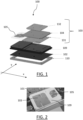
- FIG. 1 presents an exploded view of an antenna system 100 with a GNSS dual antenna 103 and an SDARS antenna 105 both mounted on a plastic substrate 109. Said substrate is significantly positioned in a plane parallel to the x-y plane.
- FIG. 1 further presents the layers of the GNSS dual antenna 103.
- Said antenna comprises a first metal part 131 which is a GNSS parasitic element and a second metal part 132 which the GNSS drive element.
- the metal parts 131 and 132 are separated by a second plastic substrate 104. This substrate may be a 3D printed object.
- the first metal part 131 and the second metal part 132 sandwich a second plastic substrate 104.
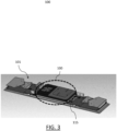
- FIG. 2 shows a view of the antenna system of FIG. 1 mounted in a TCU 101. Both antennas 103 and 105 are mounted on a same plane which is the surface of the plastic substrate 109.
- the plastic substrate 109 is mounted on an elevated PCB 102 which itself is mounted on an antenna support frame 110.
- This configuration is according to the third configuration discussed above.
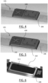
- FIG. 3 presents an assembly of the antenna system 100 on the TCU 101.
- the part 115 is the bottom housing of the TCU.
- FIG.s 4-6 show configuration examples of the antenna system on the TCU.
- FIG. 4 shows an example of the first configuration in which the antenna system 100 is directly mounted on the main PCB 106 of the TCU 101.
- FIG. 5 shows an example of the third configuration in which the antenna system is mounted on an elevated PCB 102 via support frame 110.
- FIG. 6 shows a similar example as of Fig. 5 when the elevated PCB 102 has not been mounted.
- the thickness of the support frame 110 provides a space 111 (on FIG. 6 ) between the main PCB 106 and the elevated PCB 102 delimited by the support frame 110.
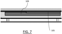
- FIG. 7 shows a sectional view of an example of the second configuration in which the antenna system is configured to form a part of a housing of the TCU.
- FIG. 8 and FIG. 9 The mean gain (as the main KPI) of the new dual band GNSS antenna and SDARS antenna with a plastic substrate are depicted respectively in FIG. 8 and FIG. 9 .
- Curves 810, 820, 830, 840, and 850 are respectively related to the angle ranges 0-20 degrees, 20-30 degrees, 30-50 degrees, 50-70 degrees, and 70-85 degrees.
- curves 910, 920, 930, 940, and 950 are respectively related to the angle ranges 0-20 degrees, 20-40 degrees, 40-60 degrees, 60-65 degrees, and 65-70 degrees.
Landscapes
- Engineering & Computer Science (AREA)
- Remote Sensing (AREA)
- Computer Security & Cryptography (AREA)
- Radar, Positioning & Navigation (AREA)
- Support Of Aerials (AREA)
Abstract
It is provided an antenna system of a vehicle telematic control unit (TCU) comprising a global navigation satellite system (GNSS) dual antenna, and a satellite digital audio radio service (SOARS) antenna. The GNSS dual antenna and the SOARS antenna are mounted on a first plastic substrate. This forms an improved antenna system.
Description
- The present invention relates to the field of antennas, and more specifically to an antenna system of a vehicle telematic control unit. It is also related to a TCU comprising said antenna system, and a vehicle comprising said TCU.
- Various types of antennas are used in the automotive industry to implement various applications (radio, navigation, or telephony). Multiband antenna systems are also commonly used in the automotive industry. Such an antenna system includes a small number of antennas to cover and operate at multiple frequency ranges and/or for redundancy reasons.
- An antenna system can be installed on the roof surface of a vehicle to let the antennas have an unobstructed view overhead. This antenna system is generally connected to one or more electronic devices (e.g., a cellular phone) inside the passenger compartment of the vehicle, such that the antenna system is operable for transmitting and/or receiving signals to/from the electronic device inside the vehicle.
- The role of the Telematics Control Unit (TCU) in a car is to control wireless tracking, diagnostics and communication to and from the vehicle using such an antenna system. Typically a TCU is embedded onboard on a vehicle.
- TCUs are becoming more and more limited in space so as to satisfy vehicle design requirements. Electronic vehicle components for the TCU therefore need to become as small as possible to satisfy the vehicle manufacturing design requirements and fit the necessary amount of components within the TCU.
- Within this context, there is a need for an improved antenna system for a vehicle TCU.
- It is therefore provided an antenna system of a vehicle telematic control unit comprising a global navigation satellite system (GNSS) dual antenna, and a satellite digital audio radio service (SDARS) antenna. The GNSS dual antenna and the SDARS antenna are mounted on a first plastic substrate.
- The antenna system may comprise one or more of the following features:
- the antenna system has a height between 5 and 10mm, preferably between 5 and 7mm, and more preferably about 6mm;
- the antenna system has a width between 100 and 150mm, preferably between 110 and 130mm, and more preferably about 120mm;
- the antenna system has a depth between 50 and 75mm, preferably between 65 and 70mm, and more preferably about 68mm;
- the GNSS antenna and the SDARS antenna are positioned aside each other and on a same plane;
- the first plastic has a plurality of positional parameters and a plurality of dimensional parameters, said positional parameters and said dimensional parameters being configured to optimize a performance metric of the antenna system;
- the GNSS dual antenna is a dual band antenna having a first metal part and a second metal part, the first metal part and the second metal part sandwich a second plastic substrate;
- the first plastic substrate and/or the second plastic substrate are made of Acrylonitrile Butadiene Styrene (ABS); and/or
- the SDARS antenna covers the Sirius XM frequency band.
- It is further provided a TCU comprising the antenna system, the antenna system being configured to be mounted on a main PCB of the TCU.
- It is further provided a TCU comprising the antenna system, the antenna system being configured to form a part of a housing of the TCU.
- It is further provided a TCU comprising the antenna system, and an antenna support frame mounted on a main PCB of the TCU. The TCU further comprises an elevated PCB mounted on the antennas support frame. The antenna system is configured to be mounted on the elevated PCB. The antenna support frame may be made of metal.
- It is further provided a vehicle comprising a TCU according to any one of the above.
- Non-limiting examples will now be described in reference to the accompanying drawings, where:
-
FIG. 1 presents an exploded view of an example of the antenna system; -
FIG. 2 presents a photo of an example of the antenna system mounted on a TCU; -
FIG. 3 presents a perspective view of an example of the antenna system mounted on a TCU; -
FIG.s 4 and 5 present a perspective view of two examples of the antenna system, -
FIG. 6 presents a perspective view of a mounting slot for an example of the antenna system according toFIG. 5 ; -
FIG. 7 presents a side view of another example of the antenna system; and -
FIG.s 8 and 9 present simulation results of an example of the antenna system. - It is provided an antenna system of a vehicle telematic control unit (TCU). The antenna system comprises a global navigation satellite system (GNSS) dual antenna, and a satellite digital audio radio service (SDARS) antenna. The GNSS dual antenna and the SDARS antenna are mounted on a first plastic substrate. This means that the first plastic surface is in physical contact with the GNSS antenna and SDARS antenna.
- Such an antenna system constitutes a combined GNSS/SDARS antenna system to be used in the TCU of a vehicle, in particular a terrestrial vehicle such as an automobile, a motorcycle, or a truck. This constitutes an improved solution, as the GNSS antenna and the SDARS antenna are placed (i.e., mounted) on a plastic substrate. Compared to ceramic substrates which are widely used in the field of antennas, such a plastic substrate provides more flexibility to a designer to set antenna's geometry.
- As known, any antenna herein is an interface between radio waves propagating through space and electric currents moving in metal conductors, used with a transmitter or receiver. In transmission, a radio transmitter may supply an electric current to the terminals of the antenna, and the antenna may radiate the energy from the current as electromagnetic waves (radio waves). In reception, the antenna may intercept some of the power of a radio wave in order to produce an electric current at its terminals, that is applied to a receiver to be amplified. As known, GNSS antennas and SDARS antennas only have receiver functionality.
- It is also provided a TCU comprising an antenna system as described herein.
- As known, a TCU in the automobile industry such as the TCU herein is an embedded system on board of a vehicle that wirelessly connects the vehicle to cloud services or other vehicles over a cellular network. The TCU collects telemetry data from the vehicle, such as position, speed, engine data, connectivity quality, etc., from various sub-systems over data and control busses. The TCU has a main printed circuit board (PCB) on which a plurality of elements, antennas, sensors, controllers, or busses may be mounted. A TCU comprising the antenna system is particularly suitable for being installed inside a vehicle, such as a car. For example, the TCU may be installed inside the dashboard or under the roof of the car. Installing the TCU in such an area can therefore provide for additional useable space inside the dashboard or under the roof for other components, such as other components for placing upon the PCB.
- As known, a PCB such the PCB herein is a medium used to connect electronic components to one another in a controlled manner. The PCB is in the form of a laminated sandwich structure of conductive and insulating layers: each of the conductive layers is designed with a pattern of traces, planes and/or other features, etched from one or more sheet layers of copper laminated onto and/or between sheet layers of a non-conductive substrate. Electrical components may be fixed to conductive pads on the outer layers in the shape designed to accept the component's terminals, generally by means of soldering, to both electrically connect and mechanically fasten them to the PCB. Additionally or alternatively, connections may be made using vias (plated-through holes that allow interconnections between layers).
- It is also provided a vehicle comprising the TCU.
- Examples of the antenna system are now discussed.
- Dimensions of the antenna system may be according to dimensions of a TCU in which the antenna system is to be mounted. The dimensions of the TCU may be small enough to be installable inside a vehicle, for example inside the dashboard, under the roof, or inside the body.
- In examples, the antenna system may have a height between 5 and 7mm, a width between 100 and 150mm, and a depth between 50 and 75mm. The depth and the width are the lengths of the antenna system on a plane parallel to the plane of the TCU (e.g., an x-y plane). The height, or equivalently thickness is a length of the antenna system orthogonal to said plane (e.g., along a z-axis). Said height may be preferably about 6mm. Said width may be preferably between 110 and 130mm, and more preferably about 120mm. Said depth may be preferably between 65 and 70mm, and more preferably about 68mm. Such dimensions make the antenna system perfectly employable in modern TCUs for vehicles.
- By "being about a specified value X" it is meant being in a range of 10 percent, preferably 5 percent below and above said value X.
- In examples, both of the GNSS antenna and the SDARS antenna of the antenna system are positioned aside each other and on a same plane. This improves the performance of each of the antennas while helping to reduce of the thickness of the antenna system (and thereby the final TCU). By "being positioned aside each other" it is meant that said antennas are not positioned (even partially) on top of each other (i.e., no overlap), and their distance is significantly small compared to their dimensions (e.g., below 5 percent or below 2 percent, for example relative to their diameter, i.e. the longest straight segment joining two points of each respective component). By "being on a same plane" it is meant that said antennas reside on a same plane upon some dents or protrusions over said plane. For example, a significant amount of surface areas of said antennas (e.g., above 90 percent or 95 percent) reside on said plane. In examples, said plane may be the same plane as of the first plastic substrate.
- The first plastic substrate has a plurality of positional and a plurality of dimensional parameters. Said positional parameters may define a position of the first plastic substrate with respect to the TCU. Said dimensional parameters may define a shape/geometry of said first plastic substrate.
- In examples, said positional parameters and said dimensional parameters may be configured to optimize a performance metric of the antenna system. By "a performance metric of the antenna system", it is meant a metric representing a combined performance of the GNSS antenna and of the SDARS antenna. Such a performance metric may be defined as a function of a first performance metric for the GNSS antenna and a second performance metric for the SDARS antenna. The function may be a summation, a maximum or a minimum. The first performance metric and the second performance metric may be the same, though evaluated on a different antenna. A performance metric may be a metric known in the field, for example, any of: an efficiency, an average gain in zenith (i.e., the highest elevation angle), or an average gain in different (i.e., a plurality of) elevation angles. As known, by an "elevation angle" it is meant the angle between the horizontal plane and the line of sight. By "being configured to optimize a performance metric" it is meant that said parameters (positional and/or dimensional) are the result of an optimization program in which the positional parameters and/or dimensional parameters of the first substrate are the free variables and said performance metric is an objective function of said optimization program. The optimization program may further consider one or more other objective functions and/or optimization constraints.
- The GNSS dual antenna may comprise a first metal part and a second metal part. The GNSS dual antenna may further comprise a second plastic substrate. The first metal part, the second metal part, and the second plastic substrate may be arranged on top of each other. For example, the first metal part and the second metal part may sandwich the second plastic substrate. In other words, the second plastic substrate may be between the first metal part and the second metal part. The GNSS dual antenna may operate at two frequency bands L1 and L5. A microstrip patch antenna with a stacked structure and a single feed may be used for the purpose of dual-band operation. The GNSS may have two metal parts (i.e., the first metal part and the second metal part) in order to cover both L1 and L5 bands. The metal part for the L5 (see 131 in
FIG. 1 ) is bigger than the metal part for L1 (see 132 inFIG. 1 ). The metal part for L5 is beneath the part for L1 and used also as a reflector for L1 metal part. A single feed may be used to excite the L1 metal part directly and the L5 part is parasitically fed by coupling to the L1 part. The second plastic substrate (see 104 inFIG. 1 ) is to separate the GNSS drive element (which corresponds to L1 band) and the GNSS parasitic element (which corresponds to L5 band). - The GNSS antenna metal element sizes, shapes and the placement of the feeding point and the position and size of the slots are designed to ensure the RHCP (right hand circular polarization) and to optimize the performance both for the average gain in zenith as well as lower elevation angles.
- The SDARS antenna may cover the Sirius XM frequency band, i.e., 2.3325 GHz - 2.345 GHz. A single feed may be used to excite the SDARS antenna. The SDARS antenna metal element sizes, shapes and the placement of the feeding point and position and size of the slots are designed to ensure the LHCP (left hand circular polarization) and to optimize the performance both for the average gain in zenith as well as low elevation angles.
- In examples, the first plastic substrate and/or the second plastic substrate are made of Acrylonitrile Butadiene Styrene (ABS).
- An antenna system as discussed above may be mounted in different configurations in a respective TCU.
- According to a first example configuration, the first plastic substrate is configured to be mounted on a main PCB of the TCU. In other words, there is no gap between the first plastic substrate and the main PCB. Such configuration helps reducing the thickness of the TCU.
- Thereby, the first configuration provides a TCU comprising an antenna system as discussed above. In such a TCU, the antenna system is configured to be mounted on a main PCB of the TCU.
- According to a second example configuration, the first plastic surface forms a part of a housing of the TCU. For example, the plastic surface may form part of the top housing of the TCU and be mounted over the main PCB when the top housing is closed. The housing of the TCU may be made of plastic. There might be a gap between the main PCB and the first plastic substrate. The gap may be up to 5 mm, preferably between 2mm and 3mm. The presence of such a gap creates a space between the first plastic substrate and the main PCB. In examples, the TCU may comprise other modules chipset in said space, for example network access devices (NADs). This provides a solution in which more chipsets can be integrated in a TCU of a given dimension.
- Thereby the second configuration provides a TCU comprising an antenna system as discussed above. In such a TCU, the antenna system is configured to form a part of a housing of the TCU.
- According to the third example configuration, the antenna system may be configured to be mounted on an elevated PCB. By an elevated PCB it is meant a PCB other than the main PCB of the TCU and which is positioned at a distance (e.g., a constant distance) with respect to the main PCB, i.e., elevated. Such an elevated PCB may be configured to be mounted on a support frame. The support frame may be mounted on the main PCB. The support frame may be of a rectangular shape and/or of a constant thickness.
- In examples, the support frame may be made of plastic or metal, preferably metal. A metal support frame herein may be made of aluminum, copper, brass, nickel, silver, steel (for example stainless steel), and/or tin. A metal support frame is able to provide a solid ground for the elevated PCB since it is connected to the ground of the elevated PCB in one side and to the ground of the main PCB on the other side/The support may be manufactured in any known method of manufacturing, for example, machining (e.g., CNC machining).
- In a third configuration, thanks to the elevation, there exists a space created between the elevated PCB and the main PCB. In examples, the TCU may comprise other modules chipset in said space, for example a network access device (NAD). This provides a solution in which more chipsets can be integrated in a TCU of a given dimension.
- Thereby the third configuration provides a TCU comprising an antenna system as discussed above, and an antenna support frame mounted on a main PCB of the TCU. The antenna system is configured to be mounted on the antenna support frame.
- Non-limiting examples of the antenna system are now discussed in reference to
FIG.s 1-7 . -
FIG. 1 presents an exploded view of anantenna system 100 with a GNSSdual antenna 103 and anSDARS antenna 105 both mounted on aplastic substrate 109. Said substrate is significantly positioned in a plane parallel to the x-y plane. -
FIG. 1 further presents the layers of the GNSSdual antenna 103. Said antenna comprises afirst metal part 131 which is a GNSS parasitic element and asecond metal part 132 which the GNSS drive element. Themetal parts plastic substrate 104. This substrate may be a 3D printed object. Thefirst metal part 131 and thesecond metal part 132 sandwich a secondplastic substrate 104. -
FIG. 2 shows a view of the antenna system ofFIG. 1 mounted in aTCU 101. Bothantennas plastic substrate 109. - Back to
FIG. 1 , theplastic substrate 109 is mounted on anelevated PCB 102 which itself is mounted on anantenna support frame 110. This configuration is according to the third configuration discussed above. -
FIG. 3 presents an assembly of theantenna system 100 on theTCU 101. Thepart 115 is the bottom housing of the TCU. -
FIG.s 4-6 show configuration examples of the antenna system on the TCU. -
FIG. 4 shows an example of the first configuration in which theantenna system 100 is directly mounted on themain PCB 106 of theTCU 101. -
FIG. 5 shows an example of the third configuration in which the antenna system is mounted on anelevated PCB 102 viasupport frame 110.FIG. 6 shows a similar example as ofFig. 5 when theelevated PCB 102 has not been mounted. The thickness of thesupport frame 110 provides a space 111 (onFIG. 6 ) between themain PCB 106 and theelevated PCB 102 delimited by thesupport frame 110. -
FIG. 7 shows a sectional view of an example of the second configuration in which the antenna system is configured to form a part of a housing of the TCU. - A number of simulations were carried out to examine the performance of the antenna system. The mean gain (as the main KPI) of the new dual band GNSS antenna and SDARS antenna with a plastic substrate are depicted respectively in
FIG. 8 and FIG. 9 .Curves - The simulations show positive results, as these are comparable to available designs in the market, but with a lower thickness.
Claims (14)
- An antenna system (100) of a vehicle telematic control unit (TCU) (101) comprising:- a global navigation satellite system (GNSS) dual antenna (103), and- a satellite digital audio radio service (SDARS) antenna (105);wherein the GNSS dual antenna and the SDARS antenna are mounted on a first plastic substrate (109).
- The antenna system of claim 1 having a height between 5 and 10mm, preferably between 5 and 7mm, and more preferably about 6mm.
- The antenna system of any of claims 1 to 2 having a width between 100 and 150mm, preferably between 110 and 130mm, and more preferably about 120mm.
- The antenna system of any of claims 1 to 3 having a depth between 50 and 75mm, preferably between 65 and 70mm, and more preferably about 68mm.
- The antenna system of any of claims 1 to 4, wherein the GNSS antenna and the SDARS antenna are positioned aside each other and on a same plane.
- The antenna system of claim 5, wherein the first plastic has a plurality of positional parameters and a plurality of dimensional parameters, said positional parameters and said dimensional parameters being configured to optimize a performance metric of the antenna system.
- The antenna system of any of claims 1 to 6, wherein the GNSS dual antenna (103) is a dual band antenna having a first metal part (131) and a second metal part (132), and the first metal part and the second metal part sandwich a second plastic substrate (104).
- The antenna system of any of claims 1 to 7, wherein the first plastic substrate and/or the second plastic substrate are made of Acrylonitrile Butadiene Styrene (ABS).
- The antenna system of any of claims 1 to 8, wherein the SDARS antenna covers the Sirius XM frequency band.
- A TCU comprising an antenna system according to any of claims 1 to 9, the antenna system being configured to be mounted on a main PCB of the TCU.
- A TCU comprising an antenna system according to any of claims 1 to 9, the antenna system being configured to form a part of a housing of the TCU.
- A TCU comprising:- an antenna system (100) according to any of claims 1 to 9,- an antenna support frame (110) mounted on a main PCB of the TCU, and- an elevated PCB mounted on the antennas support frame;wherein the antenna system is configured to be mounted on the elevated PCB.
- The TCU according to claim 12, wherein the antenna support frame is made of metal.
- A vehicle comprising the TCU of any of claims 11 to 13.
Priority Applications (1)
| Application Number | Priority Date | Filing Date | Title |
|---|---|---|---|
| EP23206473.3A EP4546558A1 (en) | 2023-10-27 | 2023-10-27 | A gnss/sdars antenna system |
Applications Claiming Priority (1)
| Application Number | Priority Date | Filing Date | Title |
|---|---|---|---|
| EP23206473.3A EP4546558A1 (en) | 2023-10-27 | 2023-10-27 | A gnss/sdars antenna system |
Publications (1)
| Publication Number | Publication Date |
|---|---|
| EP4546558A1 true EP4546558A1 (en) | 2025-04-30 |
Family
ID=88598938
Family Applications (1)
| Application Number | Title | Priority Date | Filing Date |
|---|---|---|---|
| EP23206473.3A Pending EP4546558A1 (en) | 2023-10-27 | 2023-10-27 | A gnss/sdars antenna system |
Country Status (1)
| Country | Link |
|---|---|
| EP (1) | EP4546558A1 (en) |
Citations (4)
| Publication number | Priority date | Publication date | Assignee | Title |
|---|---|---|---|---|
| EP0934608B1 (en) * | 1996-10-23 | 2002-12-18 | Thales | Antenna system for portable radiotelephone station |
| US20180083348A1 (en) * | 2016-09-16 | 2018-03-22 | Laird Technologies, Inc. | Vehicular antenna assembly including a reflector internally mounted within a radome |
| US20200185818A1 (en) * | 2018-12-10 | 2020-06-11 | Lg Electronics Inc. | Antenna system loaded in vehicle |
| US20230066184A1 (en) * | 2020-01-13 | 2023-03-02 | Lg Electronics Inc. | Antenna system mounted in vehicle |
-
2023
- 2023-10-27 EP EP23206473.3A patent/EP4546558A1/en active Pending
Patent Citations (4)
| Publication number | Priority date | Publication date | Assignee | Title |
|---|---|---|---|---|
| EP0934608B1 (en) * | 1996-10-23 | 2002-12-18 | Thales | Antenna system for portable radiotelephone station |
| US20180083348A1 (en) * | 2016-09-16 | 2018-03-22 | Laird Technologies, Inc. | Vehicular antenna assembly including a reflector internally mounted within a radome |
| US20200185818A1 (en) * | 2018-12-10 | 2020-06-11 | Lg Electronics Inc. | Antenna system loaded in vehicle |
| US20230066184A1 (en) * | 2020-01-13 | 2023-03-02 | Lg Electronics Inc. | Antenna system mounted in vehicle |
Similar Documents
| Publication | Publication Date | Title |
|---|---|---|
| CN105375104B (en) | Shark fins antenna module | |
| US8482466B2 (en) | Low profile antenna assemblies | |
| US10854964B2 (en) | Antenna apparatus and vehicle including the same | |
| CN107453028B (en) | Connector for film antenna to FAKRA | |
| US20090058731A1 (en) | Dual Band Stacked Patch Antenna | |
| CN112956078A (en) | Three-dimensional inverted-F antenna element, antenna assembly with same and communication system | |
| CN204167472U (en) | Shark fins antenna module | |
| EP3748770B1 (en) | Antenna device | |
| CN109314310B (en) | car antenna | |
| JP2011091557A (en) | Antenna device | |
| US12463330B2 (en) | Antenna device for a vehicle | |
| CN113363716B (en) | Conformal antenna formed at a surface of a vehicle | |
| JP2025170368A (en) | antenna | |
| US10897085B2 (en) | Antenna and antenna system | |
| JP7807432B2 (en) | Antenna device | |
| EP4546564A1 (en) | A full band cellular antenna | |
| US20240030624A1 (en) | Antenna device | |
| JP2017069608A (en) | Communication device | |
| JP7586854B2 (en) | Vehicle-mounted antenna device and vehicle-mounted communication system | |
| EP4518020A1 (en) | Support component for an antenna on a pcb | |
| US20240322448A1 (en) | Thin sheet-like antenna for narrowband vehicular communication | |
| JP7444022B2 (en) | Vehicle wireless communication device | |
| US20260106382A1 (en) | Vehicular antenna having a low-profile antenna assembly for non-metal surface and metal surface application | |
| CN120691134A (en) | Vehicle antenna unit | |
| KR20170092250A (en) | Feeding structure of antenna and antenna device for vehicle using thereof |
Legal Events
| Date | Code | Title | Description |
|---|---|---|---|
| PUAI | Public reference made under article 153(3) epc to a published international application that has entered the european phase |
Free format text: ORIGINAL CODE: 0009012 |
|
| STAA | Information on the status of an ep patent application or granted ep patent |
Free format text: STATUS: THE APPLICATION HAS BEEN PUBLISHED |
|
| AK | Designated contracting states |
Kind code of ref document: A1 Designated state(s): AL AT BE BG CH CY CZ DE DK EE ES FI FR GB GR HR HU IE IS IT LI LT LU LV MC ME MK MT NL NO PL PT RO RS SE SI SK SM TR |
|
| STAA | Information on the status of an ep patent application or granted ep patent |
Free format text: STATUS: REQUEST FOR EXAMINATION WAS MADE |
|
| 17P | Request for examination filed |
Effective date: 20251017 |