EP4546320A1 - DISPLAY SYSTEM, IMAGE PROCESSING DEVICE AND CORRECTION DATA GENERATING METHOD - Google Patents
DISPLAY SYSTEM, IMAGE PROCESSING DEVICE AND CORRECTION DATA GENERATING METHOD Download PDFInfo
- Publication number
- EP4546320A1 EP4546320A1 EP24207340.1A EP24207340A EP4546320A1 EP 4546320 A1 EP4546320 A1 EP 4546320A1 EP 24207340 A EP24207340 A EP 24207340A EP 4546320 A1 EP4546320 A1 EP 4546320A1
- Authority
- EP
- European Patent Office
- Prior art keywords
- correction data
- display
- image
- image processing
- covering surface
- Prior art date
- Legal status (The legal status is an assumption and is not a legal conclusion. Google has not performed a legal analysis and makes no representation as to the accuracy of the status listed.)
- Pending
Links
Images



Classifications
-
- G—PHYSICS
- G09—EDUCATION; CRYPTOGRAPHY; DISPLAY; ADVERTISING; SEALS
- G09G—ARRANGEMENTS OR CIRCUITS FOR CONTROL OF INDICATING DEVICES USING STATIC MEANS TO PRESENT VARIABLE INFORMATION
- G09G3/00—Control arrangements or circuits, of interest only in connection with visual indicators other than cathode-ray tubes
- G09G3/20—Control arrangements or circuits, of interest only in connection with visual indicators other than cathode-ray tubes for presentation of an assembly of a number of characters, e.g. a page, by composing the assembly by combination of individual elements arranged in a matrix no fixed position being assigned to or needed to be assigned to the individual characters or partial characters
-
- G—PHYSICS
- G09—EDUCATION; CRYPTOGRAPHY; DISPLAY; ADVERTISING; SEALS
- G09G—ARRANGEMENTS OR CIRCUITS FOR CONTROL OF INDICATING DEVICES USING STATIC MEANS TO PRESENT VARIABLE INFORMATION
- G09G3/00—Control arrangements or circuits, of interest only in connection with visual indicators other than cathode-ray tubes
- G09G3/20—Control arrangements or circuits, of interest only in connection with visual indicators other than cathode-ray tubes for presentation of an assembly of a number of characters, e.g. a page, by composing the assembly by combination of individual elements arranged in a matrix no fixed position being assigned to or needed to be assigned to the individual characters or partial characters
- G09G3/34—Control arrangements or circuits, of interest only in connection with visual indicators other than cathode-ray tubes for presentation of an assembly of a number of characters, e.g. a page, by composing the assembly by combination of individual elements arranged in a matrix no fixed position being assigned to or needed to be assigned to the individual characters or partial characters by control of light from an independent source
- G09G3/3406—Control of illumination source
-
- B—PERFORMING OPERATIONS; TRANSPORTING
- B60—VEHICLES IN GENERAL
- B60K—ARRANGEMENT OR MOUNTING OF PROPULSION UNITS OR OF TRANSMISSIONS IN VEHICLES; ARRANGEMENT OR MOUNTING OF PLURAL DIVERSE PRIME-MOVERS IN VEHICLES; AUXILIARY DRIVES FOR VEHICLES; INSTRUMENTATION OR DASHBOARDS FOR VEHICLES; ARRANGEMENTS IN CONNECTION WITH COOLING, AIR INTAKE, GAS EXHAUST OR FUEL SUPPLY OF PROPULSION UNITS IN VEHICLES
- B60K35/00—Instruments specially adapted for vehicles; Arrangement of instruments in or on vehicles
-
- B—PERFORMING OPERATIONS; TRANSPORTING
- B60—VEHICLES IN GENERAL
- B60K—ARRANGEMENT OR MOUNTING OF PROPULSION UNITS OR OF TRANSMISSIONS IN VEHICLES; ARRANGEMENT OR MOUNTING OF PLURAL DIVERSE PRIME-MOVERS IN VEHICLES; AUXILIARY DRIVES FOR VEHICLES; INSTRUMENTATION OR DASHBOARDS FOR VEHICLES; ARRANGEMENTS IN CONNECTION WITH COOLING, AIR INTAKE, GAS EXHAUST OR FUEL SUPPLY OF PROPULSION UNITS IN VEHICLES
- B60K35/00—Instruments specially adapted for vehicles; Arrangement of instruments in or on vehicles
- B60K35/20—Output arrangements, i.e. from vehicle to user, associated with vehicle functions or specially adapted therefor
- B60K35/21—Output arrangements, i.e. from vehicle to user, associated with vehicle functions or specially adapted therefor using visual output, e.g. blinking lights or matrix displays
- B60K35/22—Display screens
-
- B—PERFORMING OPERATIONS; TRANSPORTING
- B60—VEHICLES IN GENERAL
- B60K—ARRANGEMENT OR MOUNTING OF PROPULSION UNITS OR OF TRANSMISSIONS IN VEHICLES; ARRANGEMENT OR MOUNTING OF PLURAL DIVERSE PRIME-MOVERS IN VEHICLES; AUXILIARY DRIVES FOR VEHICLES; INSTRUMENTATION OR DASHBOARDS FOR VEHICLES; ARRANGEMENTS IN CONNECTION WITH COOLING, AIR INTAKE, GAS EXHAUST OR FUEL SUPPLY OF PROPULSION UNITS IN VEHICLES
- B60K35/00—Instruments specially adapted for vehicles; Arrangement of instruments in or on vehicles
- B60K35/20—Output arrangements, i.e. from vehicle to user, associated with vehicle functions or specially adapted therefor
- B60K35/29—Instruments characterised by the way in which information is handled, e.g. showing information on plural displays or prioritising information according to driving conditions
-
- B—PERFORMING OPERATIONS; TRANSPORTING
- B60—VEHICLES IN GENERAL
- B60K—ARRANGEMENT OR MOUNTING OF PROPULSION UNITS OR OF TRANSMISSIONS IN VEHICLES; ARRANGEMENT OR MOUNTING OF PLURAL DIVERSE PRIME-MOVERS IN VEHICLES; AUXILIARY DRIVES FOR VEHICLES; INSTRUMENTATION OR DASHBOARDS FOR VEHICLES; ARRANGEMENTS IN CONNECTION WITH COOLING, AIR INTAKE, GAS EXHAUST OR FUEL SUPPLY OF PROPULSION UNITS IN VEHICLES
- B60K35/00—Instruments specially adapted for vehicles; Arrangement of instruments in or on vehicles
- B60K35/60—Instruments characterised by their location or relative disposition in or on vehicles
-
- B—PERFORMING OPERATIONS; TRANSPORTING
- B60—VEHICLES IN GENERAL
- B60R—VEHICLES, VEHICLE FITTINGS, OR VEHICLE PARTS, NOT OTHERWISE PROVIDED FOR
- B60R11/00—Arrangements for holding or mounting articles, not otherwise provided for
- B60R11/02—Arrangements for holding or mounting articles, not otherwise provided for for radio sets, television sets, telephones, or the like; Arrangement of controls thereof
-
- B—PERFORMING OPERATIONS; TRANSPORTING
- B60—VEHICLES IN GENERAL
- B60R—VEHICLES, VEHICLE FITTINGS, OR VEHICLE PARTS, NOT OTHERWISE PROVIDED FOR
- B60R11/00—Arrangements for holding or mounting articles, not otherwise provided for
- B60R11/02—Arrangements for holding or mounting articles, not otherwise provided for for radio sets, television sets, telephones, or the like; Arrangement of controls thereof
- B60R11/0229—Arrangements for holding or mounting articles, not otherwise provided for for radio sets, television sets, telephones, or the like; Arrangement of controls thereof for displays, e.g. cathodic tubes
-
- G—PHYSICS
- G06—COMPUTING OR CALCULATING; COUNTING
- G06T—IMAGE DATA PROCESSING OR GENERATION, IN GENERAL
- G06T7/00—Image analysis
- G06T7/0002—Inspection of images, e.g. flaw detection
- G06T7/0004—Industrial image inspection
- G06T7/001—Industrial image inspection using an image reference approach
-
- G—PHYSICS
- G06—COMPUTING OR CALCULATING; COUNTING
- G06T—IMAGE DATA PROCESSING OR GENERATION, IN GENERAL
- G06T7/00—Image analysis
- G06T7/90—Determination of colour characteristics
-
- B—PERFORMING OPERATIONS; TRANSPORTING
- B60—VEHICLES IN GENERAL
- B60K—ARRANGEMENT OR MOUNTING OF PROPULSION UNITS OR OF TRANSMISSIONS IN VEHICLES; ARRANGEMENT OR MOUNTING OF PLURAL DIVERSE PRIME-MOVERS IN VEHICLES; AUXILIARY DRIVES FOR VEHICLES; INSTRUMENTATION OR DASHBOARDS FOR VEHICLES; ARRANGEMENTS IN CONNECTION WITH COOLING, AIR INTAKE, GAS EXHAUST OR FUEL SUPPLY OF PROPULSION UNITS IN VEHICLES
- B60K2360/00—Indexing scheme associated with groups B60K35/00 or B60K37/00 relating to details of instruments or dashboards
- B60K2360/18—Information management
- B60K2360/195—Blocking or enabling display functions
-
- B—PERFORMING OPERATIONS; TRANSPORTING
- B60—VEHICLES IN GENERAL
- B60K—ARRANGEMENT OR MOUNTING OF PROPULSION UNITS OR OF TRANSMISSIONS IN VEHICLES; ARRANGEMENT OR MOUNTING OF PLURAL DIVERSE PRIME-MOVERS IN VEHICLES; AUXILIARY DRIVES FOR VEHICLES; INSTRUMENTATION OR DASHBOARDS FOR VEHICLES; ARRANGEMENTS IN CONNECTION WITH COOLING, AIR INTAKE, GAS EXHAUST OR FUEL SUPPLY OF PROPULSION UNITS IN VEHICLES
- B60K2360/00—Indexing scheme associated with groups B60K35/00 or B60K37/00 relating to details of instruments or dashboards
- B60K2360/20—Optical features of instruments
- B60K2360/33—Illumination features
- B60K2360/332—Light emitting diodes
-
- B—PERFORMING OPERATIONS; TRANSPORTING
- B60—VEHICLES IN GENERAL
- B60R—VEHICLES, VEHICLE FITTINGS, OR VEHICLE PARTS, NOT OTHERWISE PROVIDED FOR
- B60R11/00—Arrangements for holding or mounting articles, not otherwise provided for
- B60R2011/0001—Arrangements for holding or mounting articles, not otherwise provided for characterised by position
- B60R2011/0003—Arrangements for holding or mounting articles, not otherwise provided for characterised by position inside the vehicle
- B60R2011/0005—Dashboard
-
- G—PHYSICS
- G06—COMPUTING OR CALCULATING; COUNTING
- G06T—IMAGE DATA PROCESSING OR GENERATION, IN GENERAL
- G06T2207/00—Indexing scheme for image analysis or image enhancement
- G06T2207/30—Subject of image; Context of image processing
- G06T2207/30108—Industrial image inspection
- G06T2207/30121—CRT, LCD or plasma display
-
- G—PHYSICS
- G06—COMPUTING OR CALCULATING; COUNTING
- G06T—IMAGE DATA PROCESSING OR GENERATION, IN GENERAL
- G06T2207/00—Indexing scheme for image analysis or image enhancement
- G06T2207/30—Subject of image; Context of image processing
- G06T2207/30248—Vehicle exterior or interior
- G06T2207/30268—Vehicle interior
-
- G—PHYSICS
- G09—EDUCATION; CRYPTOGRAPHY; DISPLAY; ADVERTISING; SEALS
- G09G—ARRANGEMENTS OR CIRCUITS FOR CONTROL OF INDICATING DEVICES USING STATIC MEANS TO PRESENT VARIABLE INFORMATION
- G09G2320/00—Control of display operating conditions
- G09G2320/02—Improving the quality of display appearance
- G09G2320/0233—Improving the luminance or brightness uniformity across the screen
-
- G—PHYSICS
- G09—EDUCATION; CRYPTOGRAPHY; DISPLAY; ADVERTISING; SEALS
- G09G—ARRANGEMENTS OR CIRCUITS FOR CONTROL OF INDICATING DEVICES USING STATIC MEANS TO PRESENT VARIABLE INFORMATION
- G09G2320/00—Control of display operating conditions
- G09G2320/02—Improving the quality of display appearance
- G09G2320/0242—Compensation of deficiencies in the appearance of colours
-
- G—PHYSICS
- G09—EDUCATION; CRYPTOGRAPHY; DISPLAY; ADVERTISING; SEALS
- G09G—ARRANGEMENTS OR CIRCUITS FOR CONTROL OF INDICATING DEVICES USING STATIC MEANS TO PRESENT VARIABLE INFORMATION
- G09G2320/00—Control of display operating conditions
- G09G2320/02—Improving the quality of display appearance
- G09G2320/0271—Adjustment of the gradation levels within the range of the gradation scale, e.g. by redistribution or clipping
-
- G—PHYSICS
- G09—EDUCATION; CRYPTOGRAPHY; DISPLAY; ADVERTISING; SEALS
- G09G—ARRANGEMENTS OR CIRCUITS FOR CONTROL OF INDICATING DEVICES USING STATIC MEANS TO PRESENT VARIABLE INFORMATION
- G09G2320/00—Control of display operating conditions
- G09G2320/02—Improving the quality of display appearance
- G09G2320/0285—Improving the quality of display appearance using tables for spatial correction of display data
-
- G—PHYSICS
- G09—EDUCATION; CRYPTOGRAPHY; DISPLAY; ADVERTISING; SEALS
- G09G—ARRANGEMENTS OR CIRCUITS FOR CONTROL OF INDICATING DEVICES USING STATIC MEANS TO PRESENT VARIABLE INFORMATION
- G09G2320/00—Control of display operating conditions
- G09G2320/06—Adjustment of display parameters
- G09G2320/0626—Adjustment of display parameters for control of overall brightness
-
- G—PHYSICS
- G09—EDUCATION; CRYPTOGRAPHY; DISPLAY; ADVERTISING; SEALS
- G09G—ARRANGEMENTS OR CIRCUITS FOR CONTROL OF INDICATING DEVICES USING STATIC MEANS TO PRESENT VARIABLE INFORMATION
- G09G2320/00—Control of display operating conditions
- G09G2320/06—Adjustment of display parameters
- G09G2320/0666—Adjustment of display parameters for control of colour parameters, e.g. colour temperature
-
- G—PHYSICS
- G09—EDUCATION; CRYPTOGRAPHY; DISPLAY; ADVERTISING; SEALS
- G09G—ARRANGEMENTS OR CIRCUITS FOR CONTROL OF INDICATING DEVICES USING STATIC MEANS TO PRESENT VARIABLE INFORMATION
- G09G2320/00—Control of display operating conditions
- G09G2320/06—Adjustment of display parameters
- G09G2320/0693—Calibration of display systems
-
- G—PHYSICS
- G09—EDUCATION; CRYPTOGRAPHY; DISPLAY; ADVERTISING; SEALS
- G09G—ARRANGEMENTS OR CIRCUITS FOR CONTROL OF INDICATING DEVICES USING STATIC MEANS TO PRESENT VARIABLE INFORMATION
- G09G2354/00—Aspects of interface with display user
-
- G—PHYSICS
- G09—EDUCATION; CRYPTOGRAPHY; DISPLAY; ADVERTISING; SEALS
- G09G—ARRANGEMENTS OR CIRCUITS FOR CONTROL OF INDICATING DEVICES USING STATIC MEANS TO PRESENT VARIABLE INFORMATION
- G09G2360/00—Aspects of the architecture of display systems
- G09G2360/14—Detecting light within display terminals, e.g. using a single or a plurality of photosensors
- G09G2360/144—Detecting light within display terminals, e.g. using a single or a plurality of photosensors the light being ambient light
-
- G—PHYSICS
- G09—EDUCATION; CRYPTOGRAPHY; DISPLAY; ADVERTISING; SEALS
- G09G—ARRANGEMENTS OR CIRCUITS FOR CONTROL OF INDICATING DEVICES USING STATIC MEANS TO PRESENT VARIABLE INFORMATION
- G09G2360/00—Aspects of the architecture of display systems
- G09G2360/16—Calculation or use of calculated indices related to luminance levels in display data
-
- G—PHYSICS
- G09—EDUCATION; CRYPTOGRAPHY; DISPLAY; ADVERTISING; SEALS
- G09G—ARRANGEMENTS OR CIRCUITS FOR CONTROL OF INDICATING DEVICES USING STATIC MEANS TO PRESENT VARIABLE INFORMATION
- G09G2380/00—Specific applications
- G09G2380/10—Automotive applications
Definitions
- the disclosures herein relate to display systems, image processing devices, and correction data generating methods, and are particularly suitable for use in the display system in which a front surface of a display part is covered with a patterned covering surface having a plurality of micropores, an image processing device applied thereto, and a correction data generating method.
- JP 2001-331132 A Conventionally, there has been known a technology to provide necessary visual information by a display when in use, and provide an appearance that conceals the display during nonuse (e.g., see JP 2001-331132 A ).
- An on-vehicle display device disclosed in JP 2001-331132 A is fitted into a wood-grain panel of an instrument panel of a vehicle, and the front surface of the display, which emits display light to an outside when lit, is covered with a wood-grain screen having a large number of micropores through which display light can be transmitted.
- the wood-grain screen hides the display when the display is not lit, so that the entire instrument panel, including the part in which the display is fitted, is unified into a wood-grain pattern.
- Shytech such a technology in which an image is displayed on a display only when necessary is referred to as Shytech, and it has attracted attention as a technology to display a screen on an interior portion with a pattern such as wood grain or fabric.
- the interior portion in which Shytech is implemented is not a display space optimized for screen display, there has been a problem that the image displayed on the screen and a pattern on the interior portion overlap and the displayed image becomes difficult to see.
- An object of the present invention is to reduce the problem that a display image of a display part seen through micropores and a pattern on a covering surface overlap to make the display image difficult to see, in a display system in which the front surface of the display part is covered with a patterned covering surface having many micropores.
- a display system wherein a front surface of a display part is covered with a covering surface which is patterned, and has a number, particularly a large number, of micropores, includes a correction data storage part configured to store correction data generated by gradation inversion of luminance distribution data appearing on the covering surface when a single color is uniformly displayed on a whole of the display part, and an image processing part configured to correct image data to be displayed on the display part by the correction data read from the correction data storage part.
- the image data to be displayed on the display part is corrected by the correction equivalent to canceling the pattern of the covering surface.
- the correction equivalent to canceling the pattern of the covering surface it is possible to reduce the problem that the display image of the display part seen through the micropores overlaps with the pattern of the covering surface, making the display image difficult to see, and to improve quality of the display image.
- FIG. 1 is a drawing schematically illustrating a configuration example of a display system according to an embodiment.
- the display system according to the present embodiment includes an image processing device 1, a display device 2, and an instrument panel 3.
- the image processing device 1 is a device to generate image data to be displayed on the display part of the display device 2, and supplies generated image data to the display device 2.
- the image processing device 1 inputs image data generated by an on-vehicle device (not shown), corrects the input image data based on correction data, and supplies corrected image data to the display device 2.
- the image processing device 1 may store an application program for image generation, corrects the image data generated by execution of the application program based on the correction data, and supplies the corrected image data to the display device 2.
- the display device 2 is, for example, a liquid crystal display, an organic electroluminescence display, or an LED display, and includes a light source, a driver, and a display part.
- the display device 2 receives image data from the image processing device 1, controls the light source and the driver based on the image data, and displays an image based on the image data on the display part.
- the display part includes a display panel.
- the instrument panel 3 corresponds to the covering surface of the claims, and the display device 2 is installed on the back of the instrument panel 3 (inside a dashboard or console where the instrument panel 3 is installed), and the front surface of the display part of the display device 2 is covered with the instrument panel 3.
- the display part of the display device 2 and the instrument panel 3 are not required to have the same size, and the entire display part may be covered by the instrument panel 3.
- the instrument panel 3 is provided with an arbitrary pattern such as a grain pattern or a fabric pattern.
- the instrument panel 3 has a number of micropores, particularly a large number of micropores, through which display light output through the display part can be transmitted.
- the display light of the display part is transmitted forward through the micropores of the instrument panel 3, so that the display image of the display part can be seen through the instrument panel 3.
- the image is not seen on the instrument panel 3, and the entire instrument panel 3 is unified with a pattern such as a grain pattern.
- FIG. 2 is a front view illustrating an instrument panel 3 viewed from the front, and FIG. 2 (a) shows a state when the light source is not turned on, and FIG. 2 (b) shows a state when the light source is turned on. FIG. 2 (b) shows a state in which an image based on uncorrected image data is displayed.
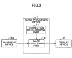
- FIG. 3 is a block diagram illustrating an example of a functional configuration of the image processing device 1.
- the image processing device 1 of the present embodiment includes a correction data storage part 11 and an image processing part 12.
- the image processing part 12 executes the following processing in cooperation with hardware and software.
- the processing of the image processing part 12 is executed by operating a program stored in a storage medium such as a RAM, a ROM, a hard disk, or a semiconductor memory under the control of a microcomputer including a CPU, a RAM, a ROM, and the like.
- a DSP Digital Signal Processor
- GPU Graphics Processing Unit
- the correction data storage part 11 stores correction data generated in advance, for example, when the display system is manufactured or mounted on a vehicle.
- the correction data is generated by inverting the gradation of the data of the luminance distribution appearing on the instrument panel 3 when the entire display part is uniformly displayed with the same color under the condition that the ambient illuminance of the instrument panel 3 is controlled to be in a predetermined state.
- FIG. 4 is a drawing describing a correction data generating method.
- the correction data is generated, for example, by an image analysis device (not shown).
- FIG. 4 (a) is a front view showing a state of the instrument panel 3 as viewed from the front, and shows a state when the light source portion of the display device 2 is not lit. As described above, when the light source portion is not lit, no image is visible on the instrument panel 3, and the entire instrument panel 3 is unified with a pattern such as wood grain.
- step S1 Under a state in which the ambient illuminance of the instrument panel 3 shown in FIG. 4 (a) is controlled to be a predetermined state, an image of the instrument panel 3 is captured from the front of the instrument panel 3 with the entire display part of the display device 2 uniformly displayed in white (step S1).
- a state in which the ambient illuminance of the instrument panel 3 is controlled to be a predetermined state means, for example, a state in which the surface of the instrument panel 3 is uniformly irradiated with external light at a predetermined illuminance in a dark room.
- the display device 2 displays a solid white image (hereinafter referred to as white image) on the entire display part.
- white image a solid white image
- the display light of the white image is transmitted forward through the micropores of the instrument panel 3, so that the white image and the pattern of the instrument panel 3 overlap from the front of the instrument panel 3.
- the image of the instrument panel 3 in this state is captured by a camera from the front.
- the image analysis device acquires luminance distribution data of the surface of the instrument panel 3 by analyzing the captured image data of the instrument panel 3 (step S2).
- FIG. 4 (b) shows the luminance distribution data acquired in this way, that is, the luminance distribution data of the surface of the instrument panel 3 obtained when a white image is displayed over the entire display part under the condition that the ambient illuminance of the instrument panel 3 is controlled to be in a predetermined state.
- the luminance distribution data acquired here is luminance distribution data of a region facing the entire surface of the display part out of the entire surface of the instrument panel 3.
- the image analysis device generates correction data by performing gradation inversion of the luminance distribution data of the instrument panel 3 (step S3).
- FIG. 4 (c) shows correction data generated by performing gradation inversion (negative-positive inversion) of the luminance distribution data of FIG. 4 (b) .
- the data generated as described above is stored as correction data in the correction data storage part 11. Since the pattern of the instrument panel 3 mounted on each vehicle differs from vehicle to vehicle, correction data reflecting the pattern of the instrument panel 3 is generated for each display system mounted on each vehicle and stored in the correction data storage part 11 of each vehicle.
- the image processing device 1 may generate the correction data described above.
- the image processing part 12 corrects the image data to be displayed on the display part of the display device 2 by the correction data read from the correction data storage part 11.
- the image processing part 12 corrects the original image data input from the in-vehicle device 100 based on the correction data stored in the correction data storage part 11, and supplies the image data which is corrected (hereinafter referred to as corrected image data) to the display device 2.
- the image processing part 12 performs correction processing by superimposing the correction data on the original image data.
- FIG. 5 is a drawing illustrating an example of correction processing by the image processing part 12.
- FIG. 5 (a) shows the original image data input to the image processing part 12, and
- FIG. 5 (b) shows the correction data stored in the correction data storage part 11.
- the image processing part 12 performs processing by superimposing the correction data of FIG. 5 (b) on the original image data of FIG. 5 (a).
- FIG. 5 (c) shows corrected image data generated by this correction.
- FIG. 5 (d) shows a state in which the instrument panel 3 is seen from the front when a corrected image is displayed on the display part of the display device 2 based on the corrected image data.
- the corrected image data shown in FIG. 5 (c) is image data in which a correction equivalent to canceling the pattern of the instrument panel 3 is performed on the original image data shown in FIG. 5 (a) . Therefore, when a corrected image based on the corrected image data is displayed on the display part, the pattern of the instrument panel 3 becomes difficult to be seen due to the components of the correction data included in the corrected image that can be seen through the micropores of the instrument panel 3, and the original image becomes easy to see without being obstructed by the pattern of the instrument panel 3 as shown in FIG. 5 (d) .
- an illuminance measuring device to measure ambient illuminance of the instrument panel 3 may be installed in the vehicle, and the image processing part 12 corrects the image data by the correction data corresponding to the ambient illuminance of the instrument panel 3 measured by the illuminance measuring device.
- a plurality of correction data generated under a plurality of situations where the ambient illuminance of the instrument panel 3 differs are stored in the correction data storage part 11 in association with the corresponding ambient illuminance. More specifically, for example, when the display system is manufactured or mounted on a vehicle, the illuminance of the external light irradiated on the surface of the instrument panel 3 in a dark room is changed, and a plurality of correction data corresponding to the respective ambient illuminances are generated and stored in the correction data storage part 11.
- the image processing part 12 reads correction data corresponding to the ambient illuminances measured by the illuminance measuring device from the correction data storage part 11, and corrects the image data using the read-out correction data.
- the image processing part 12 uses, for example, correction data associated with the ambient illuminances closest to the ambient illuminances measured by the illuminance measuring device.
- the image data may be corrected using an average value or a median value of two correction data associated with two ambient illuminances closest to the ambient illuminances measured by the illuminance measuring device. The average value or the median value may be calculated for each pixel of the correction data, or may be calculated for each block that collectively constitutes a plurality of neighboring pixels.
- one set of correction data generated under a situation where the ambient illuminance of the instrument panel 3 is managed to be in a predetermined state is stored in the correction data storage part 11. More specifically, as described above, for example, when the display system is manufactured or mounted on a vehicle, external light emitted to the surface of the instrument panel 3 in a dark room is set to a predetermined illuminance, and correction data is generated under that situation and stored in the correction data storage part 11.
- the image processing part 12 adjusts the correction data read from the correction data storage part 11 based on a predetermined function using the ambient illuminance measured by the illuminance measuring device as an explanatory variable, and corrects the image data by the adjusted correction data.
- the predetermined function used here can be obtained, for example, as follows. That is, a plurality of correction data are generated under a plurality of situations where the ambient illuminance of the instrument panel 3 is different, and an interpolation function is obtained from the plurality of ambient illuminances used at this time and the plurality of correction data.
- the interpolation function may be calculated for each pixel of the correction data, or it may be calculated for each block that collectively constitutes a plurality of neighboring pixels.
- the interpolation function may be a function expressed by a polynomial or an approximation function using a lookup table.
- the image data to be displayed on the display part is corrected by the correction data, using the data generated by gradation inversion of the luminance distribution data appearing on the surface of the instrument panel 3 when the entire display part is uniformly displayed in the same color.
- the image data to be displayed on the display part is subjected to a correction equivalent to canceling the pattern of the instrument panel 3.
- the problem that the display image of the display part seen through the micropores overlaps with the pattern of the instrument panel 3 makes it difficult to see the display image can be reduced, and the quality of the display image can be improved.
- the display color is not limited to white.
- it may be gray or the same color as the color of the instrument panel 3.
- the present invention is not limited to this.
- the present invention is not limited to a type of display system in which the display device 2 is incorporated and fixed inside a dashboard or the like, but may be applied to a portable display system in which the image processing device 1, the display device 2, and the covering surface are configured to be portable.
Landscapes
- Engineering & Computer Science (AREA)
- Mechanical Engineering (AREA)
- Theoretical Computer Science (AREA)
- Physics & Mathematics (AREA)
- General Physics & Mathematics (AREA)
- Chemical & Material Sciences (AREA)
- Combustion & Propulsion (AREA)
- Transportation (AREA)
- Computer Hardware Design (AREA)
- Computer Vision & Pattern Recognition (AREA)
- Quality & Reliability (AREA)
- Controls And Circuits For Display Device (AREA)
- Instrument Panels (AREA)
- Transforming Electric Information Into Light Information (AREA)
- Control Of Indicators Other Than Cathode Ray Tubes (AREA)
Abstract
A display system, wherein a front surface of a display part is covered with a covering surface which is patterned, and has a number of micropores, includes a correction data storage part configured to store correction data generated by gradation inversion of luminance distribution data appearing on the covering surface when a single color is uniformly displayed on a whole of the display part, and an image processing part configured to correct image data to be displayed on the display part by the correction data read from the correction data storage part.

Description
- The disclosures herein relate to display systems, image processing devices, and correction data generating methods, and are particularly suitable for use in the display system in which a front surface of a display part is covered with a patterned covering surface having a plurality of micropores, an image processing device applied thereto, and a correction data generating method.
- Conventionally, there has been known a technology to provide necessary visual information by a display when in use, and provide an appearance that conceals the display during nonuse (e.g., see
JP 2001-331132 A JP 2001-331132 A - In recent years, such a technology in which an image is displayed on a display only when necessary is referred to as Shytech, and it has attracted attention as a technology to display a screen on an interior portion with a pattern such as wood grain or fabric. However, since the interior portion in which Shytech is implemented is not a display space optimized for screen display, there has been a problem that the image displayed on the screen and a pattern on the interior portion overlap and the displayed image becomes difficult to see.
- An object of the present invention is to reduce the problem that a display image of a display part seen through micropores and a pattern on a covering surface overlap to make the display image difficult to see, in a display system in which the front surface of the display part is covered with a patterned covering surface having many micropores.
- The present disclosure relates to a display system, an image processing device and correction data generating method according to the appended claims. Embodiments are disclosed in the dependent claims. According to an aspect of the present disclosure, a display system, wherein a front surface of a display part is covered with a covering surface which is patterned, and has a number, particularly a large number, of micropores, includes a correction data storage part configured to store correction data generated by gradation inversion of luminance distribution data appearing on the covering surface when a single color is uniformly displayed on a whole of the display part, and an image processing part configured to correct image data to be displayed on the display part by the correction data read from the correction data storage part.
- According to the present disclosure configured as described above, the image data to be displayed on the display part is corrected by the correction equivalent to canceling the pattern of the covering surface. As a result, it is possible to reduce the problem that the display image of the display part seen through the micropores overlaps with the pattern of the covering surface, making the display image difficult to see, and to improve quality of the display image.
-
FIG. 1 is a drawing schematically illustrating a configuration example of a display system according to an embodiment; -
FIG. 2 is a front view illustrating an instrument panel viewed from the front; -
FIG. 3 is a block diagram illustrating an example of a functional configuration of an image processing device according to an embodiment; -
FIG. 4 is a drawing describing a correction data generating method according to an embodiment; and -
FIG. 5 is a drawing illustrating an example of correction processing by the image processing part according to an embodiment. - In the following, embodiments of the present invention will be described with reference to the accompanying drawings.
FIG. 1 is a drawing schematically illustrating a configuration example of a display system according to an embodiment. In the present embodiment, as an example, a configuration when the display system is applied to an inside of a vehicle is shown. As shown inFIG. 1 , the display system according to the present embodiment includes animage processing device 1, adisplay device 2, and aninstrument panel 3. - The
image processing device 1 is a device to generate image data to be displayed on the display part of thedisplay device 2, and supplies generated image data to thedisplay device 2. For example, theimage processing device 1 inputs image data generated by an on-vehicle device (not shown), corrects the input image data based on correction data, and supplies corrected image data to thedisplay device 2. Alternatively, theimage processing device 1 may store an application program for image generation, corrects the image data generated by execution of the application program based on the correction data, and supplies the corrected image data to thedisplay device 2. - The
display device 2 is, for example, a liquid crystal display, an organic electroluminescence display, or an LED display, and includes a light source, a driver, and a display part. Thedisplay device 2 receives image data from theimage processing device 1, controls the light source and the driver based on the image data, and displays an image based on the image data on the display part. The display part includes a display panel. - The
instrument panel 3 corresponds to the covering surface of the claims, and thedisplay device 2 is installed on the back of the instrument panel 3 (inside a dashboard or console where theinstrument panel 3 is installed), and the front surface of the display part of thedisplay device 2 is covered with theinstrument panel 3. The display part of thedisplay device 2 and theinstrument panel 3 are not required to have the same size, and the entire display part may be covered by theinstrument panel 3. - The
instrument panel 3 is provided with an arbitrary pattern such as a grain pattern or a fabric pattern. In addition, theinstrument panel 3 has a number of micropores, particularly a large number of micropores, through which display light output through the display part can be transmitted. When the light source part of thedisplay device 2 is turned on, the display light of the display part is transmitted forward through the micropores of theinstrument panel 3, so that the display image of the display part can be seen through theinstrument panel 3. Conversely, when the light source part is not turned on, the image is not seen on theinstrument panel 3, and theentire instrument panel 3 is unified with a pattern such as a grain pattern. -
FIG. 2 is a front view illustrating aninstrument panel 3 viewed from the front, andFIG. 2 (a) shows a state when the light source is not turned on, andFIG. 2 (b) shows a state when the light source is turned on.FIG. 2 (b) shows a state in which an image based on uncorrected image data is displayed. -
FIG. 3 is a block diagram illustrating an example of a functional configuration of theimage processing device 1. As shown inFIG. 3 , theimage processing device 1 of the present embodiment includes a correctiondata storage part 11 and animage processing part 12. Theimage processing part 12 executes the following processing in cooperation with hardware and software. For example, the processing of theimage processing part 12 is executed by operating a program stored in a storage medium such as a RAM, a ROM, a hard disk, or a semiconductor memory under the control of a microcomputer including a CPU, a RAM, a ROM, and the like. In addition to the microcomputer, a DSP (Digital Signal Processor), a GPU (Graphics Processing Unit), and the like may be provided. - The correction
data storage part 11 stores correction data generated in advance, for example, when the display system is manufactured or mounted on a vehicle. The correction data is generated by inverting the gradation of the data of the luminance distribution appearing on theinstrument panel 3 when the entire display part is uniformly displayed with the same color under the condition that the ambient illuminance of theinstrument panel 3 is controlled to be in a predetermined state. -
FIG. 4 is a drawing describing a correction data generating method. The correction data is generated, for example, by an image analysis device (not shown).FIG. 4 (a) is a front view showing a state of theinstrument panel 3 as viewed from the front, and shows a state when the light source portion of thedisplay device 2 is not lit. As described above, when the light source portion is not lit, no image is visible on theinstrument panel 3, and theentire instrument panel 3 is unified with a pattern such as wood grain. - First, under a state in which the ambient illuminance of the
instrument panel 3 shown inFIG. 4 (a) is controlled to be a predetermined state, an image of theinstrument panel 3 is captured from the front of theinstrument panel 3 with the entire display part of thedisplay device 2 uniformly displayed in white (step S1). A state in which the ambient illuminance of theinstrument panel 3 is controlled to be a predetermined state means, for example, a state in which the surface of theinstrument panel 3 is uniformly irradiated with external light at a predetermined illuminance in a dark room. - Under a state in which the ambient illuminance is controlled in this way, the
display device 2 displays a solid white image (hereinafter referred to as white image) on the entire display part. As a result, the display light of the white image is transmitted forward through the micropores of theinstrument panel 3, so that the white image and the pattern of theinstrument panel 3 overlap from the front of theinstrument panel 3. The image of theinstrument panel 3 in this state is captured by a camera from the front. - Next, the image analysis device acquires luminance distribution data of the surface of the
instrument panel 3 by analyzing the captured image data of the instrument panel 3 (step S2).FIG. 4 (b) shows the luminance distribution data acquired in this way, that is, the luminance distribution data of the surface of theinstrument panel 3 obtained when a white image is displayed over the entire display part under the condition that the ambient illuminance of theinstrument panel 3 is controlled to be in a predetermined state. The luminance distribution data acquired here is luminance distribution data of a region facing the entire surface of the display part out of the entire surface of theinstrument panel 3. - Next, the image analysis device generates correction data by performing gradation inversion of the luminance distribution data of the instrument panel 3 (step S3).
FIG. 4 (c) shows correction data generated by performing gradation inversion (negative-positive inversion) of the luminance distribution data ofFIG. 4 (b) . - In the present embodiment, the data generated as described above is stored as correction data in the correction
data storage part 11. Since the pattern of theinstrument panel 3 mounted on each vehicle differs from vehicle to vehicle, correction data reflecting the pattern of theinstrument panel 3 is generated for each display system mounted on each vehicle and stored in the correctiondata storage part 11 of each vehicle. Theimage processing device 1 may generate the correction data described above. - Referring back to
FIG. 3 , the description continues. Theimage processing part 12 corrects the image data to be displayed on the display part of thedisplay device 2 by the correction data read from the correctiondata storage part 11. In the example ofFIG. 3 , theimage processing part 12 corrects the original image data input from the in-vehicle device 100 based on the correction data stored in the correctiondata storage part 11, and supplies the image data which is corrected (hereinafter referred to as corrected image data) to thedisplay device 2. For example, theimage processing part 12 performs correction processing by superimposing the correction data on the original image data. -
FIG. 5 is a drawing illustrating an example of correction processing by theimage processing part 12.FIG. 5 (a) shows the original image data input to theimage processing part 12, andFIG. 5 (b) shows the correction data stored in the correctiondata storage part 11. Theimage processing part 12 performs processing by superimposing the correction data ofFIG. 5 (b) on the original image data ofFIG. 5 (a). FIG. 5 (c) shows corrected image data generated by this correction.FIG. 5 (d) shows a state in which theinstrument panel 3 is seen from the front when a corrected image is displayed on the display part of thedisplay device 2 based on the corrected image data. - The corrected image data shown in
FIG. 5 (c) is image data in which a correction equivalent to canceling the pattern of theinstrument panel 3 is performed on the original image data shown inFIG. 5 (a) . Therefore, when a corrected image based on the corrected image data is displayed on the display part, the pattern of theinstrument panel 3 becomes difficult to be seen due to the components of the correction data included in the corrected image that can be seen through the micropores of theinstrument panel 3, and the original image becomes easy to see without being obstructed by the pattern of theinstrument panel 3 as shown inFIG. 5 (d) . - It should be noted that the ambient illuminance of the
instrument panel 3 varies depending on the situation (time, driving location, weather, etc.) when the display system is used in the vehicle. Therefore, an illuminance measuring device to measure ambient illuminance of theinstrument panel 3 may be installed in the vehicle, and theimage processing part 12 corrects the image data by the correction data corresponding to the ambient illuminance of theinstrument panel 3 measured by the illuminance measuring device. - As an example, a plurality of correction data generated under a plurality of situations where the ambient illuminance of the
instrument panel 3 differs are stored in the correctiondata storage part 11 in association with the corresponding ambient illuminance. More specifically, for example, when the display system is manufactured or mounted on a vehicle, the illuminance of the external light irradiated on the surface of theinstrument panel 3 in a dark room is changed, and a plurality of correction data corresponding to the respective ambient illuminances are generated and stored in the correctiondata storage part 11. When the display system is used, theimage processing part 12 reads correction data corresponding to the ambient illuminances measured by the illuminance measuring device from the correctiondata storage part 11, and corrects the image data using the read-out correction data. - Note that, there may be a case where none of the ambient illuminances associated with the correction data stored in the correction
data storage part 11 matches the ambient illuminances measured by the illuminance measuring device. In this case, theimage processing part 12 uses, for example, correction data associated with the ambient illuminances closest to the ambient illuminances measured by the illuminance measuring device. Alternatively, the image data may be corrected using an average value or a median value of two correction data associated with two ambient illuminances closest to the ambient illuminances measured by the illuminance measuring device. The average value or the median value may be calculated for each pixel of the correction data, or may be calculated for each block that collectively constitutes a plurality of neighboring pixels. - As another example, the following may be performed. That is, one set of correction data generated under a situation where the ambient illuminance of the
instrument panel 3 is managed to be in a predetermined state is stored in the correctiondata storage part 11. More specifically, as described above, for example, when the display system is manufactured or mounted on a vehicle, external light emitted to the surface of theinstrument panel 3 in a dark room is set to a predetermined illuminance, and correction data is generated under that situation and stored in the correctiondata storage part 11. When the display system is used, theimage processing part 12 adjusts the correction data read from the correctiondata storage part 11 based on a predetermined function using the ambient illuminance measured by the illuminance measuring device as an explanatory variable, and corrects the image data by the adjusted correction data. - The predetermined function used here can be obtained, for example, as follows. That is, a plurality of correction data are generated under a plurality of situations where the ambient illuminance of the
instrument panel 3 is different, and an interpolation function is obtained from the plurality of ambient illuminances used at this time and the plurality of correction data. The interpolation function may be calculated for each pixel of the correction data, or it may be calculated for each block that collectively constitutes a plurality of neighboring pixels. The interpolation function may be a function expressed by a polynomial or an approximation function using a lookup table. - As described above in detail, in the present embodiment, in the display system in which the front surface of the display part of the
display device 2 is covered with a patterned covering surface (instrument panel 3) having a particularly large number of micropores, the image data to be displayed on the display part is corrected by the correction data, using the data generated by gradation inversion of the luminance distribution data appearing on the surface of theinstrument panel 3 when the entire display part is uniformly displayed in the same color. - According to the present embodiment configured as described above, the image data to be displayed on the display part is subjected to a correction equivalent to canceling the pattern of the
instrument panel 3. Thus, the problem that the display image of the display part seen through the micropores overlaps with the pattern of theinstrument panel 3 makes it difficult to see the display image can be reduced, and the quality of the display image can be improved. - Although the above-described embodiment has described an example in which an image of the same color uniformly displayed on the entire display part is used as a white image, the display color is not limited to white. For example, it may be gray or the same color as the color of the
instrument panel 3. - Although the above-described embodiment has described an example in which the display system of the present embodiment is applied to a vehicle, the present invention is not limited to this. For example, the present invention is not limited to a type of display system in which the
display device 2 is incorporated and fixed inside a dashboard or the like, but may be applied to a portable display system in which theimage processing device 1, thedisplay device 2, and the covering surface are configured to be portable. - Further, the present invention is not limited to these embodiments, and various variations and modifications may be made without departing from the scope of the claims.
Claims (6)
- A display system, wherein a front surface of a display part is covered with a covering surface which is patterned, and has a number of micropores, comprising:a correction data storage part configured to store correction data generated by gradation inversion of luminance distribution data appearing on the covering surface when a single color is uniformly displayed on a whole of the display part; andan image processing part configured to correct image data to be displayed on the display part by the correction data read from the correction data storage part.
- The display system according to claim 1, wherein the correction data used by the image processing part to correct the image data corresponds to ambient illuminance at the covering surface measured by an illuminance measuring device.
- The display system according to claim 2, wherein the correction data storage part is configured to store a plurality of correction data in association with corresponding ambient illuminances, the plurality of correction data being generated under a plurality of situations in which ambient illuminance at the covering surface is different, and wherein the image processing part is configured to read the correction data corresponding to the ambient illuminance measured by the illuminance measuring device from the correction data storage part, and to correct the image data by using the correction data which is read out.
- The display system according to claim 2 or 3, wherein the correction data storage part is configured to store correction data generated under a condition in which ambient illuminance at the covering surface is controlled to be in a predetermined state, and wherein the image processing part is configured to adjust the correction data read from the correction data storage part based on a predetermined function using the ambient illuminance measured by the illuminance measuring device as an explanatory variable, and to correct the image data by the adjusted correction data.
- An image processing device, which is configured to be applied to a display system, wherein a front surface of a display part is covered with a covering surface which is patterned, and has a number of micropores, the image processing device comprising:a correction data storage part configured to store correction data generated by gradation inversion of luminance distribution data appearing on the covering surface when a single color is uniformly displayed on a whole of the display part; andan image processing part configured to correct image data to be displayed on the display part by the correction data read from the correction data storage part.
- A correction data generating method of generating correction data used to correct image data to be displayed on a display part in a display system in which a front surface of the display part is covered with a covering surface which is patterned, and has a number of micropores, comprising:capturing an image of the covering surface from a front of the covering surface in a state where a single color is uniformly displayed on a whole of the display part;acquiring luminance distribution data from captured image data of the covering surface; andgenerating the correction data by inverting the luminance distribution data.
Applications Claiming Priority (1)
| Application Number | Priority Date | Filing Date | Title |
|---|---|---|---|
| JP2023183300A JP2025072873A (en) | 2023-10-25 | 2023-10-25 | DISPLAY SYSTEM, IMAGE PROCESSING DEVICE, AND METHOD FOR GENERATING CORRECTION DATA |
Publications (1)
| Publication Number | Publication Date |
|---|---|
| EP4546320A1 true EP4546320A1 (en) | 2025-04-30 |
Family
ID=93154495
Family Applications (1)
| Application Number | Title | Priority Date | Filing Date |
|---|---|---|---|
| EP24207340.1A Pending EP4546320A1 (en) | 2023-10-25 | 2024-10-17 | DISPLAY SYSTEM, IMAGE PROCESSING DEVICE AND CORRECTION DATA GENERATING METHOD |
Country Status (4)
| Country | Link |
|---|---|
| US (1) | US20250140212A1 (en) |
| EP (1) | EP4546320A1 (en) |
| JP (1) | JP2025072873A (en) |
| CN (1) | CN119889194A (en) |
Citations (4)
| Publication number | Priority date | Publication date | Assignee | Title |
|---|---|---|---|---|
| JP2001331132A (en) | 2000-05-23 | 2001-11-30 | Yazaki Corp | Display device |
| US20220223114A1 (en) * | 2021-01-08 | 2022-07-14 | Samsung Display Co., Ltd. | Tiled display device having a plurality of display panels |
| US20230015959A1 (en) * | 2021-07-15 | 2023-01-19 | Shanghai Tianma Micro-electronics Co., Ltd. | Display device |
| US20230335031A1 (en) * | 2022-04-15 | 2023-10-19 | Microsoft Technology Licensing, Llc | Spectral sensing-based adaptive control of display color |
-
2023
- 2023-10-25 JP JP2023183300A patent/JP2025072873A/en active Pending
-
2024
- 2024-10-11 US US18/913,106 patent/US20250140212A1/en active Pending
- 2024-10-17 CN CN202411451470.XA patent/CN119889194A/en active Pending
- 2024-10-17 EP EP24207340.1A patent/EP4546320A1/en active Pending
Patent Citations (5)
| Publication number | Priority date | Publication date | Assignee | Title |
|---|---|---|---|---|
| JP2001331132A (en) | 2000-05-23 | 2001-11-30 | Yazaki Corp | Display device |
| US20020054440A1 (en) * | 2000-05-23 | 2002-05-09 | Yazaki Corporation | Display device |
| US20220223114A1 (en) * | 2021-01-08 | 2022-07-14 | Samsung Display Co., Ltd. | Tiled display device having a plurality of display panels |
| US20230015959A1 (en) * | 2021-07-15 | 2023-01-19 | Shanghai Tianma Micro-electronics Co., Ltd. | Display device |
| US20230335031A1 (en) * | 2022-04-15 | 2023-10-19 | Microsoft Technology Licensing, Llc | Spectral sensing-based adaptive control of display color |
Also Published As
| Publication number | Publication date |
|---|---|
| CN119889194A (en) | 2025-04-25 |
| US20250140212A1 (en) | 2025-05-01 |
| JP2025072873A (en) | 2025-05-12 |
Similar Documents
| Publication | Publication Date | Title |
|---|---|---|
| US11501727B2 (en) | Circuit device, display device, electronic apparatus, mobile body, and control method | |
| EP3590752B1 (en) | Head-up display device and onboard display system | |
| KR102307501B1 (en) | Optical compensation system and Optical compensation method thereof | |
| JP2008148055A (en) | Image processing apparatus, image processing method, display apparatus, and projection display apparatus | |
| JP2015142276A5 (en) | ||
| JP2012198464A (en) | Display control device, image display system, and display control method | |
| JP2020046469A (en) | Correction data generation device, computer program, method for generating correction data and method for manufacturing display panel | |
| JP2020123138A (en) | Image processing apparatus, image processing method, program, and storage medium | |
| JP6779695B2 (en) | Image processing device and its control method, display device | |
| JP2016133799A (en) | Illumination system | |
| JP2006030600A (en) | Multi-screen display system, multi-screen display method, brightness correction method, and program | |
| US20250140212A1 (en) | Display system, image processing device, and correction data generating method | |
| CN108550341B (en) | Display device and display method | |
| JP4710403B2 (en) | Vehicular image generation apparatus and method | |
| CN117524139B (en) | Display device and control method | |
| US20110050739A1 (en) | Image processor and image processing method | |
| JP5207832B2 (en) | Display device | |
| JP2007281893A (en) | Projector system | |
| JP2009020206A (en) | Rear projection type liquid crystal display device | |
| JP2012008199A (en) | Display control device, display system and display control method | |
| JP5331020B2 (en) | Display control apparatus, display system, and display control method | |
| JP2019032403A (en) | Display device, control method thereof, program, and storage medium | |
| JP2011232483A (en) | Display control unit, display system, and display control method | |
| JP2010122400A (en) | Liquid crystal display control device, liquid crystal display control method, and liquid crystal display control program | |
| WO2013038596A1 (en) | Image display device and signal processing program |
Legal Events
| Date | Code | Title | Description |
|---|---|---|---|
| PUAI | Public reference made under article 153(3) epc to a published international application that has entered the european phase |
Free format text: ORIGINAL CODE: 0009012 |
|
| STAA | Information on the status of an ep patent application or granted ep patent |
Free format text: STATUS: THE APPLICATION HAS BEEN PUBLISHED |
|
| AK | Designated contracting states |
Kind code of ref document: A1 Designated state(s): AL AT BE BG CH CY CZ DE DK EE ES FI FR GB GR HR HU IE IS IT LI LT LU LV MC ME MK MT NL NO PL PT RO RS SE SI SK SM TR |
|
| STAA | Information on the status of an ep patent application or granted ep patent |
Free format text: STATUS: REQUEST FOR EXAMINATION WAS MADE |
|
| 17P | Request for examination filed |
Effective date: 20251023 |