EP4545890A1 - Refrigerator and control method therefor - Google Patents
Refrigerator and control method therefor Download PDFInfo
- Publication number
- EP4545890A1 EP4545890A1 EP23826192.9A EP23826192A EP4545890A1 EP 4545890 A1 EP4545890 A1 EP 4545890A1 EP 23826192 A EP23826192 A EP 23826192A EP 4545890 A1 EP4545890 A1 EP 4545890A1
- Authority
- EP
- European Patent Office
- Prior art keywords
- ice making
- housing
- unit
- connector
- refrigerator
- Prior art date
- Legal status (The legal status is an assumption and is not a legal conclusion. Google has not performed a legal analysis and makes no representation as to the accuracy of the status listed.)
- Pending
Links
Images

Classifications
-
- F—MECHANICAL ENGINEERING; LIGHTING; HEATING; WEAPONS; BLASTING
- F25—REFRIGERATION OR COOLING; COMBINED HEATING AND REFRIGERATION SYSTEMS; HEAT PUMP SYSTEMS; MANUFACTURE OR STORAGE OF ICE; LIQUEFACTION SOLIDIFICATION OF GASES
- F25C—PRODUCING, WORKING OR HANDLING ICE
- F25C1/00—Producing ice
- F25C1/04—Producing ice by using stationary moulds
-
- F—MECHANICAL ENGINEERING; LIGHTING; HEATING; WEAPONS; BLASTING
- F25—REFRIGERATION OR COOLING; COMBINED HEATING AND REFRIGERATION SYSTEMS; HEAT PUMP SYSTEMS; MANUFACTURE OR STORAGE OF ICE; LIQUEFACTION SOLIDIFICATION OF GASES
- F25D—REFRIGERATORS; COLD ROOMS; ICE-BOXES; COOLING OR FREEZING APPARATUS NOT OTHERWISE PROVIDED FOR
- F25D17/00—Arrangements for circulating cooling fluids; Arrangements for circulating gas, e.g. air, within refrigerated spaces
- F25D17/04—Arrangements for circulating cooling fluids; Arrangements for circulating gas, e.g. air, within refrigerated spaces for circulating air, e.g. by convection
- F25D17/06—Arrangements for circulating cooling fluids; Arrangements for circulating gas, e.g. air, within refrigerated spaces for circulating air, e.g. by convection by forced circulation
-
- F—MECHANICAL ENGINEERING; LIGHTING; HEATING; WEAPONS; BLASTING
- F25—REFRIGERATION OR COOLING; COMBINED HEATING AND REFRIGERATION SYSTEMS; HEAT PUMP SYSTEMS; MANUFACTURE OR STORAGE OF ICE; LIQUEFACTION SOLIDIFICATION OF GASES
- F25C—PRODUCING, WORKING OR HANDLING ICE
- F25C2400/00—Auxiliary features or devices for producing, working or handling ice
- F25C2400/10—Refrigerator units
-
- F—MECHANICAL ENGINEERING; LIGHTING; HEATING; WEAPONS; BLASTING
- F25—REFRIGERATION OR COOLING; COMBINED HEATING AND REFRIGERATION SYSTEMS; HEAT PUMP SYSTEMS; MANUFACTURE OR STORAGE OF ICE; LIQUEFACTION SOLIDIFICATION OF GASES
- F25D—REFRIGERATORS; COLD ROOMS; ICE-BOXES; COOLING OR FREEZING APPARATUS NOT OTHERWISE PROVIDED FOR
- F25D2317/00—Details or arrangements for circulating cooling fluids; Details or arrangements for circulating gas, e.g. air, within refrigerated spaces, not provided for in other groups of this subclass
- F25D2317/06—Details or arrangements for circulating cooling fluids; Details or arrangements for circulating gas, e.g. air, within refrigerated spaces, not provided for in other groups of this subclass with forced air circulation
- F25D2317/061—Details or arrangements for circulating cooling fluids; Details or arrangements for circulating gas, e.g. air, within refrigerated spaces, not provided for in other groups of this subclass with forced air circulation through special compartments
-
- F—MECHANICAL ENGINEERING; LIGHTING; HEATING; WEAPONS; BLASTING
- F25—REFRIGERATION OR COOLING; COMBINED HEATING AND REFRIGERATION SYSTEMS; HEAT PUMP SYSTEMS; MANUFACTURE OR STORAGE OF ICE; LIQUEFACTION SOLIDIFICATION OF GASES
- F25D—REFRIGERATORS; COLD ROOMS; ICE-BOXES; COOLING OR FREEZING APPARATUS NOT OTHERWISE PROVIDED FOR
- F25D2400/00—General features of, or devices for refrigerators, cold rooms, ice-boxes, or for cooling or freezing apparatus not covered by any other subclass
- F25D2400/30—Quick freezing
Definitions
- the present application relates to a refrigerator with an automatic ice making unit and its control method.
- the ice maker unit comprises an ice making tray and a driving motor that rotates the ice making tray.
- the driving motor rotates the ice making tray to turn its upper surface downward, so that the generated ice falls into a storage container located below the ice making tray for collection.
- Patent Document 1 Japanese Patent Application Publication No. 2006-105419 .
- the automatic ice making unit can be removed, thus enabling the area where the unit was removed to be effectively utilized as a freezing storage area.
- the air outlet is positioned to direct air that has passed through the evaporator around the ice making tray, there may be insufficient airflow to the storage container located below the ice making tray within the larger storage area.
- the area from which the automatic ice making unit is removed may not be efficiently cooled, and this area cannot be fully utilized as a freezing storage area. Consequently, achieving rapid freezing becomes a problem.
- the object of the present application is to provide a refrigerator and a control method capable of efficiently cooling an area from which an automatic ice making unit has been removed in a freezing compartment, reliably increasing a usable freezing storage area, and ensuring reliable rapid freezing performance.
- the present invention is directed to a refrigerator comprising a freezing compartment, the freezing compartment is provided with: a detachable automatic ice making unit, which comprises an ice making tray and a driving motor configured to rotate the ice making tray; a blowing port configured to direct gas that has passed through an evaporator toward the ice making tray; and a rapid freezing pipeline that is detachably mounted to an area where the automatic ice making unit has been removed;
- the rapid freezing pipeline comprises: a housing; an insertion port provided on the housing and facing the blowing port, or an ice making pipeline having the blowing port inserted into the insertion port such that the blowing port is located inside the housing; a cooling fan arranged inside the housing to increase the flow rate of the gas flowing from the blowing port into the housing and discharge the gas; and an blowing port provided on the housing for discharging the gas from the cooling fan to the outside of the housing.
- the present application utilizes the cooling fan within the housing of the rapid freezing pipeline to increase the flow rate of the gas that passes through the evaporator and exits the blowing port. This allows the gas to be supplied from the housing's blowing port into the freezing compartment. As a result, the area where the automatic ice making unit has been removed can be efficiently cooled, effectively increasing the usable freezing storage area and enabling reliable rapid freezing.
- a discharge direction of the cooling fan is downward and forms an angle between 15 and 45 degrees relative to the direction of gas flow from the blowing port.
- cooling fan's discharge direction to form an angle of 15 to 45 degrees with the direction of airflow from the blowing port, and directing it downward, cold air can be supplied to a larger storage area, including the storage container located below the blowing port. This ensures reliable and efficient cooling of the area from which the automatic ice making unit has been removed.
- the refrigerator further comprises: a controller for controlling the automatic ice making unit and the rapid freezing pipeline, and an ice-making connector that is detachably connected to the unit-side connector of the automatic ice making unit;
- the rapid freezing pipeline further comprises: a pipe-side connector detachably connected to the ice-making connector; the controller is configured to control the system such that, when the rapid freezing pipeline is installed in the area where the automatic ice making unit has been removed and the pipe-side connector is connected to the ice-making connector, power is supplied to the fan motor of the cooling fan via the connected ice-making connector and pipe-side connector.
- the wiring connected to the pipe-side connector is provided with a diode to prevent reverse polarity.
- the refrigerator is provided with a spacer located above the automatic ice making unit, and the spacer has a sliding support section with ends that extend in a front-to-back direction, both ends of the base of the automatic ice making unit are slidably inserted into a space defined by the sliding support section and the spacer.
- the automatic ice making unit slides backward under the guidance of the sliding support section until it reaches a set position, where it engages with the refrigerator, and the unit-side connector on the automatic ice making unit connects to the ice-making connector fixed to the refrigerator.
- a rear side of the housing is provided with the insertion port, and a front side of the housing is provided with the blowing port, which has a mesh-like structure.
- the present application is also directed to a control method for the refrigerator, characterized in that the control method comprises the following steps:
- control method further comprises:
- step S10 further comprises: if no signal to activate rapid freezing is received, switching to a standby state.
- the refrigerator and control method according to the present application can efficiently cool the area from which the automatic ice making unit has been removed in the freezing compartment, thereby reliably increasing the usable freezing storage area, and ensuring reliable rapid freezing.
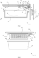
- FIG. 1 is a side cross-sectional view showing an installation structure of a rapid freezing pipeline 20 in a refrigerator 2 of the present invention.
- FIG. 2 is a front view of the rapid freezing pipeline 20 as seen along arrow A-A in FIG. 1 .
- FIG. 3 is a side cross-sectional view showing an installation structure of an automatic ice making unit 50 in the refrigerator 2 of the present invention.
- FIGS. 1 to 3 a general structure of the refrigerator 2 of the present invention is described.
- a freezer compartment 4 of the refrigerator 2 and a cooling air path 10 arranged at its rear side are shown.
- the refrigerator's refrigerator compartment not shown in the figures, is located above the freezer compartment 4.
- An evaporator 12 and a refrigerator-side fan 14 are arranged in the cooling air path 10.
- the evaporator 12 forms part of the refrigeration cycle through which refrigerant flows.
- refrigerant discharged from a compressor 6 flows through a condenser, capillary tube, and other components before entering the evaporator 12.
- the refrigerant then circulates through the heat exchange pipes of the evaporator 12 and returns to the suction side of the compressor 6.
- the air in the cooling air path 10 flows upward through the evaporator 12.
- the gas flows through the heat exchange pipes of the evaporator 12, it is cooled.
- the cooled gas then flows into the freezer compartment 4 through a blowing port 16A of an ice making pipeline 16.
- a blowing port 16A of an ice making pipeline 16 is shown here.
- the automatic ice making unit 50 is arranged inside the freezer compartment 4. Furthermore, as shown in FIGS. 1 and 2 , the rapid freezing pipeline 20 can be installed in the freezer compartment 4 after the automatic ice making unit 50 is removed. For example, in summer when ice consumption is higher, the refrigerator 2 is equipped with the automatic ice making unit 50 to make ice. On the other hand, in winter when ice consumption decreases, the automatic ice making unit 50 can be removed, and the vacant space can be used as additional freezing storage in the freezer compartment 4.
- the automatic ice making unit 50 comprises a resin-made ice making tray 52 and a drive unit 54, which includes a driving motor 54Afor rotating the ice making tray 52.
- the ice making pipeline 16, which is part of the cooling air path 10, extends to a front of the ice making tray 52, and the blowing port 16A of the ice making pipeline 16 is directed toward the ice making tray 52.
- the gas that has passed through the evaporator 12 flows into the ice making pipeline 16 under the force of the refrigerator-side fan 14.
- the gas then flows through the ice making pipeline 16 and exits through the blowing port 16A into the freezer compartment 4.
- the gas flows out from the blowing port 16A in a generally horizontal direction, slightly diffusing.
- the cooled air flows over the top, sides, and bottom surfaces of the ice making tray 52 from the rear to the front. This airflow cools the water stored in the individual compartments of the ice making tray 52, causing it to freeze.
- a controller 60 which forms part of the control system of the refrigerator 2, supplies power to the driving motor 54A of the drive unit 54, causing the ice making tray 52 to rotate. This rotation causes the upper surface of the ice making tray 52, originally facing upward, to turn downward. As the ice making tray 52 rotates, part of it engages with the refrigerator 2, and upon further rotation, the ice making tray 52 is twisted, causing the ice to detach from the compartments. The ice then falls and is collected in a storage container 44 located below the ice making tray 52.
- the refrigerator 2 is equipped with a spacer 40 located above the automatic ice making unit 50.
- the spacer 40 has a sliding support section 42, which extends in the front-to-back direction at the positions of the left and right ends of the automatic ice making unit 50.
- the sliding support section 42 forms an L-shape in its longitudinal direction (referring to FIG. 2 ). Both ends of the base of the automatic ice making unit 50 can be slidably inserted into a space defined by the L-shaped sliding support section 42 and the upper spacer 40.
- the ends of the base of the automatic ice making unit 50 can be placed into the space defined by the L-shaped sliding support section 42 and the spacer 40, and the automatic ice making unit 50 can be pushed toward the rear to install it in the freezer compartment 4. In this manner, the automatic ice making unit 50 slides backward under the guidance of the sliding support section 42 until it reaches a set position and is snap-fitted into place within the refrigerator 2.
- a unit-side connector 56 on the automatic ice making unit 50 connects to an ice-making connector 18 fixed to the refrigerator 2.
- the unit-side connector 56 can have a protruding pin, and the ice-making connector 18 can have a corresponding recess.
- the unit-side connector 56 can have a recess and the ice-making connector 18 defines a protruding pin.
- the unit-side connector 56 is electrically connected to the driving motor 54A of the drive unit 54, while the ice-making connector 18 is electrically connected to the power supply unit controlled by the controller 60.
- power from the power supply unit is supplied to the driving motor 54A through the connected ice-making connector 18 and unit-side connector 56 based on the control signals from the controller 60. This enables the ice making tray 52 to rotate by operating the driving motor 54A.
- the automatic ice making unit 50 When the automatic ice making unit 50 is removed from the freezer compartment 4, the front door of the freezer compartment 4 is opened, and the snap-fit securing the automatic ice making unit 50 is released. The automatic ice making unit 50 is then pulled forward. At this point, the unit-side connector 56 disconnects from the ice-making connector 18. In this manner, the automatic ice making unit 50 slides forward under the guidance of the sliding support section 42, making it easy to remove the unit from the freezer compartment 4.
- the automatic ice making unit 50 is detachably installed in the freezer compartment 4 of the refrigerator 2, and the unit-side connector 56 is detachably connected to the ice-making connector 18.
- the rapid freezing pipeline 20 comprises a housing 22 that defines a space through which gas flows.
- a plate-shaped sliding seat 22A extends to both sides of the housing 22.
- the ends of the sliding seat 22A on both sides are slidably inserted into the space formed by the L-shaped sliding support section 42 and the upper spacer 40.
- the rapid freezing pipeline 20 can slide back and forth under the guidance of the sliding support section 42.
- the installation and removal of the rapid freezing pipeline 20 in the freezer compartment 4 can be performed in the same manner as the automatic ice making unit 50.
- a rear surface of the housing 22 is provided with an insertion port 24.
- the ice making pipeline 16 of the refrigerator 2 is inserted into the housing 22 through this insertion port 24, so that the blowing port 16A of the ice making pipeline 16 is located inside the housing 22.
- the gas that has passed through the evaporator 12 flows into the housing 22 through the ice making pipeline 16.
- this structure is not limited to the configuration shown.
- the ice making pipeline 16 can protrude less from the cooling air path 10 to the front than shown in the figures.
- the ice making pipeline 16 does not have to be inserted into the housing 22, and instead, the blowing port 16A of the ice making pipeline 16 can be located at a rear side of the housing 22.
- the insertion port 24 By arranging the insertion port 24 to face the blowing port 16A, the gas that has passed through the evaporator 12 can flow into the housing 22.
- a cooling fan 28 is arranged inside the housing 22 inside the housing 22 .
- the gas flowing into the housing 22 from the blowing port 16A of the ice making pipeline 16 is drawn by this fan and discharged through its outlet.
- the cooling fan 28 includes a fan motor 28A that drives the rotation of the impeller.
- the cooling fan 28 is electrically connected to a pipe-side connector 30, which is fixed to the housing 22.
- the pipe-side connector 30 can be connected to the ice-making connector 18. In this way, similar to the automatic ice making unit 50, the fan motor 28A can receive power from the power supply unit of the refrigerator 2.
- a front side of the housing 22 is provided with a blowing port 26 through which the gas discharged from the cooling fan 28 exits to the outside of the housing 22.
- the blowing port 26 has a mesh-like structure formed by narrow, spaced components.
- the cooling fan 28 increases the flow speed of the incoming gas, and the gas is discharged through the blowing port 26 to the outside of the housing 22. In this way, the freezer compartment 4 can be cooled more efficiently, and rapid freezing can be implemented.
- the rapid freezing pipeline 20 can be installed in an area from which the automatic ice making unit 50 has been removed in the freezer compartment 4 in the same manner as described above. Specifically, by opening the front door of the freezer compartment 4 of the refrigerator 2, the two ends of the sliding seat 22A of the rapid freezing pipeline 20 can be placed into the space formed by the L-shaped sliding support section 42 and the spacer 40. The rapid freezing pipeline 20 is then pushed toward the rear. In this manner, the rapid freezing pipeline 20 slides backward under the guidance of the sliding support section 42 until it reaches the set position, where it is snap-fitted into place. At this point, the ice making pipeline 16 is inserted into the housing 22 through the insertion port 24.
- the pipe-side connector 30 on the rapid freezing pipeline 20 connects to the ice-making connector 18 fixed to the side of the refrigerator 2.
- the pipe-side connector 30 has the same type of pin shape as the unit-side connector 56 of the automatic ice making unit 50.
- power from the power supply unit is supplied to the fan motor 28A of the cooling fan 28 via the connected ice-making connector 18 and pipe-side connector 30, based on control signals from the controller 60, thereby activating the cooling fan 28.
- the front door of the freezer compartment 4 is opened, the snap-fit securing the rapid freezing pipeline 20 is released, and the rapid freezing pipeline 20 is pulled forward.
- the pipe-side connector 30 disconnects from the ice-making connector 18. In this manner, the rapid freezing pipeline 20 slides forward under the guidance of the sliding support section 42, making it easy to remove the pipeline from the freezer compartment 4.
- the refrigerator 2 of the present invention includes in the freezer compartment 4: the automatic ice making unit 50 being detachable with the ice making tray 52 and the driving motor 54A that rotates the ice making tray 52, the blowing port 16A through which the gas that has passed through the evaporator 12 flows toward the ice making tray 52, and the rapid freezing pipeline 20 that is detachably installed in the area where the automatic ice making unit 50 has been removed.
- the rapid freezing pipeline 20 comprises: the housing 22; the insertion port 24 provided on the housing 22, facing the blowing port 16A, or through which the ice making pipeline 16 having the blowing port 16A is inserted, such that the blowing port 16A is located inside the housing 22; the cooling fan 28 arranged inside the housing 22 to increase the flow rate of the gas flowing from the blowing port 16A into the housing 22 and discharge the gas; and the blowing port 26 provided on the housing 22 for discharging the gas from the cooling fan 28 to the outside of the housing 22.
- the flow rate of the gas that has passed through the evaporator 12 and exits the blowing port 16A is increased by the cooling fan 28 inside the housing 22 of the rapid freezing pipeline 20, and the gas is then supplied from the blowing port 26 of the housing 22 into the freezer compartment 4.
- the area from which the automatic ice making unit 50 has been removed in the freezer compartment 4 can be efficiently cooled, the usable freezing storage area can be reliably increased, and rapid freezing can be reliably implemented.
- the refrigerator 2 of the present embodiment includes: the controller 60 for controlling the automatic ice making unit 50 and the rapid freezing pipeline 20, and the ice-making connector 18 that can be detachably connected to the unit-side connector 56 of the automatic ice making unit 50;
- the rapid freezing pipeline 20 includes the pipe-side connector 30 that can be detachably connected to the ice-making connector 18;
- the controller 60 controls the system such that when the rapid freezing pipeline 20 is installed in the area from which the automatic ice making unit 50 has been removed and the pipe-side connector 30 is connected to the ice-making connector 18, power is supplied to the fan motor 28A of the cooling fan 28 via the connected ice-making connector 18 and pipe-side connector 30.
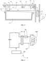
- FIG. 4 is a circuit diagram showing a wiring 32 connected to the pipe-side connector 30, which is equipped with a diode 34 to prevent reverse polarity.
- the pipe-side connector 30, fixed to the rapid freezing pipeline 20 is connected to the ice-making connector 18, fixed to the side of the refrigerator 2, there may be a problem of reverse polarity in the connector. If the connector is connected with reverse polarity while power is supplied, it can cause the fan motor 28A of the cooling fan 28 to rotate in the wrong direction, which is undesirable.
- the wiring 32 is equipped with the diode 34 to prevent reverse polarity.
- the diode 34 is installed in series with the fan motor 28A to prevent the current from flowing in the case of reverse polarity connection.
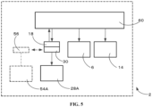
- FIG. 5 is a block diagram illustrating an example of the control system for the rapid freezing pipeline 20.
- FIG. 6 is a flowchart of the control process for the quick-freezing operation when the pipe-side connector 30 is connected to the ice-making connector 18.
- the controller 60 forms part of the control system of the refrigerator 2 and controls the compressor 6 and the refrigerator-side fan 14 for cooling the freezer compartment 4 and the refrigerator compartment. Furthermore, when the unit-side connector 56 is connected to the ice-making connector 18, the controller 60 controls the driving motor 54A of the automatic ice making unit 50. On the other hand, when the pipe-side connector 30 is connected to the ice-making connector 18, the controller 60 controls the fan motor 28A of the rapid freezing pipeline 20.
- the controller 60 can determine whether the unit-side connector 56 is connected to the ice-making connector 18. This determination can be made using any method, such as sending a detection signal from a detection terminal, or detecting the change in resistance between the detection terminals.
- a control process is performed to confirm whether the unit-side connector 56 is installed on the ice-making connector 18.
- a first step is to determine whether the front door is open (step S2). If it is determined that the front door is not open (No), this step is repeated. If the front door is open (Yes), the next step is to determine whether the unit-side connector 56 is connected to the ice-making connector 18 (step S4).
- step S6 the control process for making ice using the automatic ice making unit 50 is performed. Then, if the front door is open (step S2), the controller checks whether the unit-side connector 56 is connected to the ice-making connector 18 (step S4).
- the controller checks whether it has received a signal from the user's switch operation to activate rapid freezing (step S8). If it is determined that the signal to activate rapid freezing has not been received (No), the system enters standby mode, meaning the fan motor 28A remains off. If the signal to activate rapid freezing is received (Yes), the controller proceeds to supply power to the fan motor 28A, causing the cooling fan 28 to operate (step S10).
- the controller checks whether it has received a signal from the user's switch operation to deactivate rapid freezing (step S12). If it is determined that the signal to deactivate rapid freezing has not been received (No), the system remains in standby mode, and the fan motor 28A continues to operate, keeping the rapid freezing in effect. If the signal to deactivate rapid freezing is received (Yes), power to the fan motor 28A is stopped, which halts the rotation of the fan motor and stops the operation of the cooling fan 28 (step S14).
- step S16 The next step is to determine whether the front door is open (step S16). If it is determined that the front door is not open (No), the control process to operate/stop the cooling fan 28 (steps S8 to S14) is repeated. If the front door is open (Yes), the process returns to step S4, where it checks again whether the unit-side connector 56 is connected to the ice-making connector 18, and the control process is repeated.
- the cooling fan 28 is operated/stopped based on the user's switch operation for activating/deactivating rapid freezing.
- the controller 60 could send a signal to activate/deactivate rapid freezing based on temperature data from a temperature sensor located in the freezer compartment 4, preferably in the area where the storage container 44 is located. Based on this signal, the controller would control the operation/stop of the cooling fan 28. In this case, it is preferable to correlate the cooling fan 28 control with the compressor 6 and the refrigerator-side fan 14 for more effective cooling.
Landscapes
- Engineering & Computer Science (AREA)
- Physics & Mathematics (AREA)
- Mechanical Engineering (AREA)
- Thermal Sciences (AREA)
- General Engineering & Computer Science (AREA)
- Chemical & Material Sciences (AREA)
- Combustion & Propulsion (AREA)
- Devices That Are Associated With Refrigeration Equipment (AREA)
- Cold Air Circulating Systems And Constructional Details In Refrigerators (AREA)
Abstract
Description
- The present application relates to a refrigerator with an automatic ice making unit and its control method.
- In conventional refrigerators with an automatic ice making unit, the ice maker unit comprises an ice making tray and a driving motor that rotates the ice making tray. In such automatic ice making units, after ice is made, the driving motor rotates the ice making tray to turn its upper surface downward, so that the generated ice falls into a storage container located below the ice making tray for collection.
- A solution has been proposed for detaching the automatic ice making unit from refrigerators (for example, refer to Patent Document 1:
Japanese Patent Application Publication No. 2006-105419 - However, since the air outlet is positioned to direct air that has passed through the evaporator around the ice making tray, there may be insufficient airflow to the storage container located below the ice making tray within the larger storage area. As a result, the area from which the automatic ice making unit is removed may not be efficiently cooled, and this area cannot be fully utilized as a freezing storage area. Consequently, achieving rapid freezing becomes a problem.
- Therefore, an improved refrigerator and control method are needed to address the technical issue.
- The object of the present application is to provide a refrigerator and a control method capable of efficiently cooling an area from which an automatic ice making unit has been removed in a freezing compartment, reliably increasing a usable freezing storage area, and ensuring reliable rapid freezing performance.
- In particular, the present invention is directed to a refrigerator comprising a freezing compartment, the freezing compartment is provided with: a detachable automatic ice making unit, which comprises an ice making tray and a driving motor configured to rotate the ice making tray; a blowing port configured to direct gas that has passed through an evaporator toward the ice making tray; and a rapid freezing pipeline that is detachably mounted to an area where the automatic ice making unit has been removed; the rapid freezing pipeline comprises: a housing; an insertion port provided on the housing and facing the blowing port, or an ice making pipeline having the blowing port inserted into the insertion port such that the blowing port is located inside the housing; a cooling fan arranged inside the housing to increase the flow rate of the gas flowing from the blowing port into the housing and discharge the gas; and an blowing port provided on the housing for discharging the gas from the cooling fan to the outside of the housing.
- To achieve this, the present application utilizes the cooling fan within the housing of the rapid freezing pipeline to increase the flow rate of the gas that passes through the evaporator and exits the blowing port. This allows the gas to be supplied from the housing's blowing port into the freezing compartment. As a result, the area where the automatic ice making unit has been removed can be efficiently cooled, effectively increasing the usable freezing storage area and enabling reliable rapid freezing.
- Further, a discharge direction of the cooling fan is downward and forms an angle between 15 and 45 degrees relative to the direction of gas flow from the blowing port.
- Additionally, by configuring the cooling fan's discharge direction to form an angle of 15 to 45 degrees with the direction of airflow from the blowing port, and directing it downward, cold air can be supplied to a larger storage area, including the storage container located below the blowing port. This ensures reliable and efficient cooling of the area from which the automatic ice making unit has been removed.
- Further, the refrigerator further comprises: a controller for controlling the automatic ice making unit and the rapid freezing pipeline, and an ice-making connector that is detachably connected to the unit-side connector of the automatic ice making unit; the rapid freezing pipeline further comprises: a pipe-side connector detachably connected to the ice-making connector; the controller is configured to control the system such that, when the rapid freezing pipeline is installed in the area where the automatic ice making unit has been removed and the pipe-side connector is connected to the ice-making connector, power is supplied to the fan motor of the cooling fan via the connected ice-making connector and pipe-side connector.
- Furthermore, by using a pipe-side connector that can be detachably connected to the ice-making connector for supplying power to the automatic ice making unit, reliable power can be supplied to the fan motor of the cooling fan.
- Further, the wiring connected to the pipe-side connector is provided with a diode to prevent reverse polarity.
- In the case where the pipe-side connector is connected to the ice-making connector, there may be a risk of reverse polarity in the connector. If the connector is wrongly connected with reverse polarity while power is supplied, the fan motor of the cooling fan may rotate in the wrong direction. To prevent this, a diode is provided to prevent reverse polarity, ensuring that current flows only when the connector is correctly connected. This diode ensures that the cooling fan operates correctly at all times.
- Further, the refrigerator is provided with a spacer located above the automatic ice making unit, and the spacer has a sliding support section with ends that extend in a front-to-back direction, both ends of the base of the automatic ice making unit are slidably inserted into a space defined by the sliding support section and the spacer.
- Further, the automatic ice making unit slides backward under the guidance of the sliding support section until it reaches a set position, where it engages with the refrigerator, and the unit-side connector on the automatic ice making unit connects to the ice-making connector fixed to the refrigerator.
- Further, a rear side of the housing is provided with the insertion port, and a front side of the housing is provided with the blowing port, which has a mesh-like structure.
- The present application is also directed to a control method for the refrigerator, characterized in that the control method comprises the following steps:
- step S2: determining whether the front door of the freezing compartment is open;
- step S4: if the front door is open, determining whether the unit-side connector is connected to the ice-making connector;
- step S6: if the unit-side connector is connected to the ice-making connector, performing a control process to make ice using the automatic ice making unit;
- step S8: determining whether a signal to activate rapid freezing based on the user's switch operation is received;
- step S10: if the signal to activate rapid freezing is received, supplying power to the fan motor, causing the fan motor to rotate in the forward direction to operate the cooling fan.
- Further, the control method further comprises:
- step S12: determining whether a signal to deactivate rapid freezing based on the user's switch operation is received;
- step S14: if the signal to deactivate rapid freezing is received, stopping the power supply to the fan motor and halting the rotation of the fan motor to stop the operation of the cooling fan;
- step S16: determining whether the front door is open. If not, repeating steps S8 to S14; if yes, returning to step S4 and repeating the subsequent steps.
- Further, step S10 further comprises: if no signal to activate rapid freezing is received, switching to a standby state.
- Advantageous effects of the invention are: the refrigerator and control method according to the present application can efficiently cool the area from which the automatic ice making unit has been removed in the freezing compartment, thereby reliably increasing the usable freezing storage area, and ensuring reliable rapid freezing.
-
-
FIG. 1 is a side cross-sectional view showing an installation structure of a rapid freezing pipeline in a refrigerator of the present application; -
FIG. 2 is a front view of the rapid freezing pipeline as seen along an arrow A-A inFIG. 1 ; -
FIG. 3 is a side cross-sectional view showing an installation structure of an automatic ice making unit in the refrigerator of the present application; -
FIG. 4 is a circuit diagram of a wiring connected to a pipe-side connector, which includes a diode for preventing reverse polarity; -
FIG. 5 is a block diagram showing a control system for the rapid freezing pipeline in the refrigerator of the present application; and -
FIG. 6 is a flowchart of a control process for the quick-freezing operation in the refrigerator of the present application, where the automatic ice making unit is removed and the rapid freezing pipeline is installed, and the pipe-side connector is connected to an ice-making connector. - In order to make the objectives, technical solutions, and advantages of the present application clearer, the following detailed description of the present invention is provided in conjunction with the drawings and specific embodiments.
-
FIG. 1 is a side cross-sectional view showing an installation structure of arapid freezing pipeline 20 in arefrigerator 2 of the present invention.FIG. 2 is a front view of therapid freezing pipeline 20 as seen along arrow A-A inFIG. 1 .FIG. 3 is a side cross-sectional view showing an installation structure of an automaticice making unit 50 in therefrigerator 2 of the present invention. - Referring to
FIGS. 1 to 3 , a general structure of therefrigerator 2 of the present invention is described. InFIGS. 1 and3 , afreezer compartment 4 of therefrigerator 2 and acooling air path 10 arranged at its rear side are shown. The refrigerator's refrigerator compartment, not shown in the figures, is located above thefreezer compartment 4. - An
evaporator 12 and a refrigerator-side fan 14 are arranged in thecooling air path 10. Theevaporator 12 forms part of the refrigeration cycle through which refrigerant flows. In the refrigeration cycle, refrigerant discharged from acompressor 6 flows through a condenser, capillary tube, and other components before entering theevaporator 12. The refrigerant then circulates through the heat exchange pipes of theevaporator 12 and returns to the suction side of thecompressor 6. - By operating the refrigerator-
side fan 14, the air in thecooling air path 10 flows upward through theevaporator 12. When the gas flows through the heat exchange pipes of theevaporator 12, it is cooled. The cooled gas then flows into thefreezer compartment 4 through a blowingport 16A of anice making pipeline 16. Although other openings for the gas to enter thefreezer compartment 4 exist, only the blowingport 16A of theice making pipeline 16 is shown here. - In the
refrigerator 2 of the present embodiment, as shown inFIG. 3 , the automaticice making unit 50 is arranged inside thefreezer compartment 4. Furthermore, as shown inFIGS. 1 and 2 , the rapid freezingpipeline 20 can be installed in thefreezer compartment 4 after the automaticice making unit 50 is removed. For example, in summer when ice consumption is higher, therefrigerator 2 is equipped with the automaticice making unit 50 to make ice. On the other hand, in winter when ice consumption decreases, the automaticice making unit 50 can be removed, and the vacant space can be used as additional freezing storage in thefreezer compartment 4. - First, with reference to
FIG. 3 , the installation structure of the automaticice making unit 50 in thefreezer compartment 4 is described. The automaticice making unit 50 comprises a resin-madeice making tray 52 and adrive unit 54, which includes a driving motor 54Afor rotating theice making tray 52. Theice making pipeline 16, which is part of the coolingair path 10, extends to a front of theice making tray 52, and the blowingport 16A of theice making pipeline 16 is directed toward theice making tray 52. - The gas that has passed through the
evaporator 12 flows into theice making pipeline 16 under the force of the refrigerator-side fan 14. The gas then flows through theice making pipeline 16 and exits through the blowingport 16A into thefreezer compartment 4. The gas flows out from the blowingport 16A in a generally horizontal direction, slightly diffusing. The cooled air flows over the top, sides, and bottom surfaces of theice making tray 52 from the rear to the front. This airflow cools the water stored in the individual compartments of theice making tray 52, causing it to freeze. - While the water in the individual compartments of the
ice making tray 52 is freezing, acontroller 60, which forms part of the control system of therefrigerator 2, supplies power to the drivingmotor 54A of thedrive unit 54, causing theice making tray 52 to rotate. This rotation causes the upper surface of theice making tray 52, originally facing upward, to turn downward. As theice making tray 52 rotates, part of it engages with therefrigerator 2, and upon further rotation, theice making tray 52 is twisted, causing the ice to detach from the compartments. The ice then falls and is collected in astorage container 44 located below theice making tray 52. - The
refrigerator 2 is equipped with aspacer 40 located above the automaticice making unit 50. Thespacer 40 has a slidingsupport section 42, which extends in the front-to-back direction at the positions of the left and right ends of the automaticice making unit 50. The slidingsupport section 42 forms an L-shape in its longitudinal direction (referring toFIG. 2 ). Both ends of the base of the automaticice making unit 50 can be slidably inserted into a space defined by the L-shaped slidingsupport section 42 and theupper spacer 40. - By opening a front door of the
freezer compartment 4, the ends of the base of the automaticice making unit 50 can be placed into the space defined by the L-shaped slidingsupport section 42 and thespacer 40, and the automaticice making unit 50 can be pushed toward the rear to install it in thefreezer compartment 4. In this manner, the automaticice making unit 50 slides backward under the guidance of the slidingsupport section 42 until it reaches a set position and is snap-fitted into place within therefrigerator 2. - When the automatic
ice making unit 50 slides back to the set position, a unit-side connector 56 on the automaticice making unit 50 connects to an ice-makingconnector 18 fixed to therefrigerator 2. For example, the unit-side connector 56 can have a protruding pin, and the ice-makingconnector 18 can have a corresponding recess. Alternatively, the unit-side connector 56 can have a recess and the ice-makingconnector 18 defines a protruding pin. - The unit-
side connector 56 is electrically connected to the drivingmotor 54A of thedrive unit 54, while the ice-makingconnector 18 is electrically connected to the power supply unit controlled by thecontroller 60. In this configuration, power from the power supply unit is supplied to the drivingmotor 54A through the connected ice-makingconnector 18 and unit-side connector 56 based on the control signals from thecontroller 60. This enables theice making tray 52 to rotate by operating the drivingmotor 54A. - When the automatic
ice making unit 50 is removed from thefreezer compartment 4, the front door of thefreezer compartment 4 is opened, and the snap-fit securing the automaticice making unit 50 is released. The automaticice making unit 50 is then pulled forward. At this point, the unit-side connector 56 disconnects from the ice-makingconnector 18. In this manner, the automaticice making unit 50 slides forward under the guidance of the slidingsupport section 42, making it easy to remove the unit from thefreezer compartment 4. - As described above, the automatic
ice making unit 50 is detachably installed in thefreezer compartment 4 of therefrigerator 2, and the unit-side connector 56 is detachably connected to the ice-makingconnector 18. - Next, referring to
FIGS. 1 and 2 , the installation structure of the rapid freezingpipeline 20 in thefreezer compartment 4 is described. The rapid freezingpipeline 20 comprises ahousing 22 that defines a space through which gas flows. A plate-shaped slidingseat 22A extends to both sides of thehousing 22. As shown inFIG. 2 , the ends of the slidingseat 22A on both sides are slidably inserted into the space formed by the L-shaped slidingsupport section 42 and theupper spacer 40. In this way, the rapid freezingpipeline 20 can slide back and forth under the guidance of the slidingsupport section 42. Thus, the installation and removal of the rapid freezingpipeline 20 in thefreezer compartment 4 can be performed in the same manner as the automaticice making unit 50. - A rear surface of the
housing 22 is provided with aninsertion port 24. Theice making pipeline 16 of therefrigerator 2 is inserted into thehousing 22 through thisinsertion port 24, so that the blowingport 16A of theice making pipeline 16 is located inside thehousing 22. Thus, the gas that has passed through theevaporator 12 flows into thehousing 22 through theice making pipeline 16. - However, this structure is not limited to the configuration shown. For example, the
ice making pipeline 16 can protrude less from the coolingair path 10 to the front than shown in the figures. In this case, theice making pipeline 16 does not have to be inserted into thehousing 22, and instead, the blowingport 16A of theice making pipeline 16 can be located at a rear side of thehousing 22. By arranging theinsertion port 24 to face the blowingport 16A, the gas that has passed through theevaporator 12 can flow into thehousing 22. - Inside the
housing 22, a cooling fan 28 is arranged. The gas flowing into thehousing 22 from the blowingport 16A of theice making pipeline 16 is drawn by this fan and discharged through its outlet. By operating the cooling fan 28, the flow rate of the incoming gas can be increased before it is discharged. The cooling fan 28 includes afan motor 28A that drives the rotation of the impeller. The cooling fan 28 is electrically connected to a pipe-side connector 30, which is fixed to thehousing 22. The pipe-side connector 30 can be connected to the ice-makingconnector 18. In this way, similar to the automaticice making unit 50, thefan motor 28A can receive power from the power supply unit of therefrigerator 2. - A front side of the
housing 22 is provided with a blowingport 26 through which the gas discharged from the cooling fan 28 exits to the outside of thehousing 22. In this embodiment, the blowingport 26 has a mesh-like structure formed by narrow, spaced components. Thus, the gas that has passed through theevaporator 12 can flow into thehousing 22 from the blowingport 16A. The cooling fan 28 increases the flow speed of the incoming gas, and the gas is discharged through the blowingport 26 to the outside of thehousing 22. In this way, thefreezer compartment 4 can be cooled more efficiently, and rapid freezing can be implemented. - Furthermore, the rapid freezing
pipeline 20 can be installed in an area from which the automaticice making unit 50 has been removed in thefreezer compartment 4 in the same manner as described above. Specifically, by opening the front door of thefreezer compartment 4 of therefrigerator 2, the two ends of the slidingseat 22A of the rapid freezingpipeline 20 can be placed into the space formed by the L-shaped slidingsupport section 42 and thespacer 40. The rapid freezingpipeline 20 is then pushed toward the rear. In this manner, the rapid freezingpipeline 20 slides backward under the guidance of the slidingsupport section 42 until it reaches the set position, where it is snap-fitted into place. At this point, theice making pipeline 16 is inserted into thehousing 22 through theinsertion port 24. - When the rapid freezing
pipeline 20 slides backward and reaches the set position, the pipe-side connector 30 on the rapid freezingpipeline 20 connects to the ice-makingconnector 18 fixed to the side of therefrigerator 2. The pipe-side connector 30 has the same type of pin shape as the unit-side connector 56 of the automaticice making unit 50. - Thus, power from the power supply unit is supplied to the
fan motor 28A of the cooling fan 28 via the connected ice-makingconnector 18 and pipe-side connector 30, based on control signals from thecontroller 60, thereby activating the cooling fan 28. - When the rapid freezing
pipeline 20 is removed from thefreezer compartment 4, the front door of thefreezer compartment 4 is opened, the snap-fit securing the rapid freezingpipeline 20 is released, and the rapid freezingpipeline 20 is pulled forward. At this point, the pipe-side connector 30 disconnects from the ice-makingconnector 18. In this manner, the rapid freezingpipeline 20 slides forward under the guidance of the slidingsupport section 42, making it easy to remove the pipeline from thefreezer compartment 4. - As described above, the
refrigerator 2 of the present invention includes in the freezer compartment 4: the automaticice making unit 50 being detachable with theice making tray 52 and the drivingmotor 54A that rotates theice making tray 52, the blowingport 16A through which the gas that has passed through theevaporator 12 flows toward theice making tray 52, and the rapid freezingpipeline 20 that is detachably installed in the area where the automaticice making unit 50 has been removed. The rapid freezingpipeline 20 comprises: thehousing 22; theinsertion port 24 provided on thehousing 22, facing the blowingport 16A, or through which theice making pipeline 16 having the blowingport 16A is inserted, such that the blowingport 16A is located inside thehousing 22; the cooling fan 28 arranged inside thehousing 22 to increase the flow rate of the gas flowing from the blowingport 16A into thehousing 22 and discharge the gas; and the blowingport 26 provided on thehousing 22 for discharging the gas from the cooling fan 28 to the outside of thehousing 22. - In the
refrigerator 2 of the present embodiment, the flow rate of the gas that has passed through theevaporator 12 and exits the blowingport 16A is increased by the cooling fan 28 inside thehousing 22 of the rapid freezingpipeline 20, and the gas is then supplied from the blowingport 26 of thehousing 22 into thefreezer compartment 4. In this way, the area from which the automaticice making unit 50 has been removed in thefreezer compartment 4 can be efficiently cooled, the usable freezing storage area can be reliably increased, and rapid freezing can be reliably implemented. - Specifically, the
refrigerator 2 of the present embodiment includes: thecontroller 60 for controlling the automaticice making unit 50 and the rapid freezingpipeline 20, and the ice-makingconnector 18 that can be detachably connected to the unit-side connector 56 of the automaticice making unit 50; the rapid freezingpipeline 20 includes the pipe-side connector 30 that can be detachably connected to the ice-makingconnector 18; thecontroller 60 controls the system such that when the rapid freezingpipeline 20 is installed in the area from which the automaticice making unit 50 has been removed and the pipe-side connector 30 is connected to the ice-makingconnector 18, power is supplied to thefan motor 28A of the cooling fan 28 via the connected ice-makingconnector 18 and pipe-side connector 30. - In this way, in the present embodiment, by using the pipe-
side connector 30 that can be detachably connected to the ice-makingconnector 18 for supplying power to the automaticice making unit 50, power can be reliably supplied to thefan motor 28A of the cooling fan 28. - In the rapid freezing
pipeline 20, the discharge direction of the cooling fan 28 differs from the direction in which the gas flows out from the blowingport 16A of theice making pipeline 16, which is approximately horizontal. Specifically, as shown inFIG. 1 , the discharge direction is downward, and it forms an angle between 15 degrees and 45 degrees relative to the direction of gas flow from the blowingport 16A (θ = 15° to 45°, as shown inFIG. 1 ). In this way, cold air can be supplied to a larger storage area, including the inside of thestorage container 44 located below the blowingport 16A. This ensures that the area from which the automaticice making unit 50 has been removed in thefreezer compartment 4 can be reliably and efficiently cooled. -
FIG. 4 is a circuit diagram showing awiring 32 connected to the pipe-side connector 30, which is equipped with adiode 34 to prevent reverse polarity. When the pipe-side connector 30, fixed to the rapid freezingpipeline 20, is connected to the ice-makingconnector 18, fixed to the side of therefrigerator 2, there may be a problem of reverse polarity in the connector. If the connector is connected with reverse polarity while power is supplied, it can cause thefan motor 28A of the cooling fan 28 to rotate in the wrong direction, which is undesirable. - To address this issue, in the present embodiment, the
wiring 32 is equipped with thediode 34 to prevent reverse polarity. Thediode 34 is installed in series with thefan motor 28A to prevent the current from flowing in the case of reverse polarity connection. - By using the
diode 34 to prevent reverse polarity, current will only flow when the connectors are correctly connected, preventing current flow when the connectors are reversely connected. -
FIG. 5 is a block diagram illustrating an example of the control system for the rapid freezingpipeline 20.FIG. 6 is a flowchart of the control process for the quick-freezing operation when the pipe-side connector 30 is connected to the ice-makingconnector 18. - Next, with reference to
FIGS. 5 and6 , the control system and control method for the rapid freezingpipeline 20 are described. - The
controller 60 forms part of the control system of therefrigerator 2 and controls thecompressor 6 and the refrigerator-side fan 14 for cooling thefreezer compartment 4 and the refrigerator compartment. Furthermore, when the unit-side connector 56 is connected to the ice-makingconnector 18, thecontroller 60 controls the drivingmotor 54A of the automaticice making unit 50. On the other hand, when the pipe-side connector 30 is connected to the ice-makingconnector 18, thecontroller 60 controls thefan motor 28A of the rapid freezingpipeline 20. - The
controller 60 can determine whether the unit-side connector 56 is connected to the ice-makingconnector 18. This determination can be made using any method, such as sending a detection signal from a detection terminal, or detecting the change in resistance between the detection terminals. - In the control flow shown in
FIG. 6 , when the front door of thefreezer compartment 4 of therefrigerator 2 is opened, a control process is performed to confirm whether the unit-side connector 56 is installed on the ice-makingconnector 18. As shown inFIG. 6 , a first step is to determine whether the front door is open (step S2). If it is determined that the front door is not open (No), this step is repeated. If the front door is open (Yes), the next step is to determine whether the unit-side connector 56 is connected to the ice-making connector 18 (step S4). - In this determination, if it is found that the unit-
side connector 56 is connected to the ice-making connector 18 (Yes), the control process for making ice using the automaticice making unit 50 is performed (step S6). Then, if the front door is open (step S2), the controller checks whether the unit-side connector 56 is connected to the ice-making connector 18 (step S4). - If it is determined that the unit-
side connector 56 is not connected to the ice-making connector 18 (No), it is assumed that the pipe-side connector 30 is connected to the ice-makingconnector 18, and a control process for operating/stopping the cooling fan 28 is initiated. - First, the controller checks whether it has received a signal from the user's switch operation to activate rapid freezing (step S8). If it is determined that the signal to activate rapid freezing has not been received (No), the system enters standby mode, meaning the
fan motor 28A remains off. If the signal to activate rapid freezing is received (Yes), the controller proceeds to supply power to thefan motor 28A, causing the cooling fan 28 to operate (step S10). - In the case where the unit-
side connector 56 is not connected to the ice-makingconnector 18, even though the control for supplying power is implemented, there will be no electrical current flowing to thefan motor 28A, and the cooling fan 28 will not operate. - Next, the controller checks whether it has received a signal from the user's switch operation to deactivate rapid freezing (step S12). If it is determined that the signal to deactivate rapid freezing has not been received (No), the system remains in standby mode, and the
fan motor 28A continues to operate, keeping the rapid freezing in effect. If the signal to deactivate rapid freezing is received (Yes), power to thefan motor 28A is stopped, which halts the rotation of the fan motor and stops the operation of the cooling fan 28 (step S14). - The next step is to determine whether the front door is open (step S16). If it is determined that the front door is not open (No), the control process to operate/stop the cooling fan 28 (steps S8 to S14) is repeated. If the front door is open (Yes), the process returns to step S4, where it checks again whether the unit-
side connector 56 is connected to the ice-makingconnector 18, and the control process is repeated. - In the above control process, the cooling fan 28 is operated/stopped based on the user's switch operation for activating/deactivating rapid freezing. However, this is not the only method. For example, the
controller 60 could send a signal to activate/deactivate rapid freezing based on temperature data from a temperature sensor located in thefreezer compartment 4, preferably in the area where thestorage container 44 is located. Based on this signal, the controller would control the operation/stop of the cooling fan 28. In this case, it is preferable to correlate the cooling fan 28 control with thecompressor 6 and the refrigerator-side fan 14 for more effective cooling. - The above embodiments are intended to illustrate the technical solutions of the present invention and should not be considered as limiting. Although the present invention has been described in detail with reference to the preferred embodiment, it should be understood by those skilled in the art that modifications or equivalent substitutions can be made without departing from the spirit and scope of the present invention.
Claims (10)
- A refrigerator, comprising a freezing compartment, characterized in that:
the freezing compartment is provided with:a detachable automatic ice making unit, which comprises an ice making tray and a driving motor configured to rotate the ice making tray;a blowing port configured to direct gas that has passed through an evaporator toward the ice making tray; anda rapid freezing pipeline that is detachably mounted to an area where the automatic ice making unit has been removed;the rapid freezing pipeline comprises:a housing;an insertion port provided on the housing and facing the blowing port, or an ice making pipeline having the blowing port inserted into the insertion port such that the blowing port is located inside the housing;a cooling fan arranged inside the housing to increase the flow rate of the gas flowing from the blowing port into the housing and discharge the gas; anda blowing port provided on the housing for discharging the gas from the cooling fan to the outside of the housing. - The refrigerator according to claim 1, wherein a discharge direction of the cooling fan is downward and forms an angle between 15 and 45 degrees relative to the direction of gas flow from the blowing port.
- The refrigerator according to claim 1 or 2, wherein the refrigerator further comprises:a controller for controlling the automatic ice making unit and the rapid freezing pipeline, andan ice-making connector that is detachably connected to the unit-side connector of the automatic ice making unit;the rapid freezing pipeline further comprises:a pipe-side connector detachably connected to the ice-making connector;the controller is configured to control the system such that, when the rapid freezing pipeline is installed in the area where the automatic ice making unit has been removed and the pipe-side connector is connected to the ice-making connector, power is supplied to the fan motor of the cooling fan via the connected ice-making connector and pipe-side connector.
- The refrigerator according to claim 3, wherein the wiring connected to the pipe-side connector is provided with a diode to prevent reverse polarity.
- The refrigerator according to claim 3, wherein the refrigerator is provided with a spacer located above the automatic ice making unit, and the spacer has a sliding support section with ends that extend in a front-to-back direction, both ends of the base of the automatic ice making unit are slidably inserted into a space defined by the sliding support section and the spacer.
- The refrigerator according to claim 5, wherein the automatic ice making unit slides backward under a guidance of the sliding support section until it reaches a set position, where it engages with the refrigerator, and the unit-side connector on the automatic ice making unit connects to the ice-making connector fixed to the refrigerator.
- The refrigerator according to claim 1, wherein a rear side of the housing is provided with the insertion port, and a front side of the housing is provided with the blowing port, which has a mesh-like structure.
- A control method for the refrigerator according to any one of claims 1 to 7, characterized in that the control method comprises the following steps:step S2: determining whether the front door of the freezing compartment is open;step S4: if the front door is open, determining whether the unit-side connector is connected to the ice-making connector;step S6: if the unit-side connector is connected to the ice-making connector, performing a control process to make ice using the automatic ice making unit;step S8: determining whether a signal to activate rapid freezing based on the user's switch operation is received;step S10: if the signal to activate rapid freezing is received, supplying power to the fan motor, causing the fan motor to rotate in the forward direction to operate the cooling fan.
- The control method according to claim 8, wherein the control method further comprises:step S12: determining whether a signal to deactivate rapid freezing based on the user's switch operation is received;step S14: if the signal to deactivate rapid freezing is received, stopping the power supply to the fan motor and halting the rotation of the fan motor to stop the operation of the cooling fan;step S16: determining whether the front door is open. If not, repeating steps S8 to S14; if yes, returning to step S4 and repeating the subsequent steps.
- The control method according to claim 8, wherein step S10 further comprises: if no signal to activate rapid freezing is received, switching to a standby state.
Applications Claiming Priority (2)
| Application Number | Priority Date | Filing Date | Title |
|---|---|---|---|
| JP2022100296A JP2024001563A (en) | 2022-06-22 | 2022-06-22 | refrigerator |
| PCT/CN2023/099669 WO2023246543A1 (en) | 2022-06-22 | 2023-06-12 | Refrigerator and control method therefor |
Publications (2)
| Publication Number | Publication Date |
|---|---|
| EP4545890A1 true EP4545890A1 (en) | 2025-04-30 |
| EP4545890A4 EP4545890A4 (en) | 2025-10-15 |
Family
ID=89379154
Family Applications (1)
| Application Number | Title | Priority Date | Filing Date |
|---|---|---|---|
| EP23826192.9A Pending EP4545890A4 (en) | 2022-06-22 | 2023-06-12 | REFRIGERATOR AND ITS CONTROL METHOD |
Country Status (4)
| Country | Link |
|---|---|
| EP (1) | EP4545890A4 (en) |
| JP (1) | JP2024001563A (en) |
| CN (1) | CN119404070B (en) |
| WO (1) | WO2023246543A1 (en) |
Family Cites Families (16)
| Publication number | Priority date | Publication date | Assignee | Title |
|---|---|---|---|---|
| JP3637152B2 (en) * | 1996-06-06 | 2005-04-13 | 松下冷機株式会社 | Automatic ice making equipment |
| JPH11223450A (en) * | 1998-02-04 | 1999-08-17 | Toshiba Corp | refrigerator |
| JP2001263900A (en) * | 2000-03-21 | 2001-09-26 | Mitsubishi Electric Corp | Freezer refrigerator |
| JP4097641B2 (en) | 2004-09-30 | 2008-06-11 | 三洋電機株式会社 | Automatic ice maker and freezer refrigerator equipped with automatic ice maker |
| JP4471826B2 (en) * | 2004-12-16 | 2010-06-02 | 三洋電機株式会社 | Automatic ice maker and freezer refrigerator equipped with automatic ice maker |
| JP4097650B2 (en) * | 2004-12-16 | 2008-06-11 | 三洋電機株式会社 | Refrigerator with automatic ice machine |
| JP4310299B2 (en) * | 2005-09-09 | 2009-08-05 | 日立アプライアンス株式会社 | refrigerator |
| JP2010101517A (en) * | 2008-10-21 | 2010-05-06 | Sharp Corp | refrigerator |
| JP5218288B2 (en) * | 2009-06-05 | 2013-06-26 | パナソニック株式会社 | refrigerator |
| CN101968295B (en) * | 2009-07-27 | 2014-04-16 | 日立空调·家用电器株式会社 | refrigerator |
| JP2012007760A (en) * | 2010-06-22 | 2012-01-12 | Hitachi Appliances Inc | Refrigerator |
| KR20140039880A (en) * | 2012-09-25 | 2014-04-02 | 엘지전자 주식회사 | Ice maker kit and refrigerator having the same |
| JP2015001331A (en) * | 2013-06-14 | 2015-01-05 | ハイアールアジアインターナショナル株式会社 | Refrigerator |
| JP6211872B2 (en) * | 2013-09-26 | 2017-10-11 | 東芝ライフスタイル株式会社 | refrigerator |
| DE102016211437B4 (en) * | 2016-06-27 | 2021-09-23 | BSH Hausgeräte GmbH | Refrigerator with quick freeze function |
| JP7162339B2 (en) * | 2018-12-13 | 2022-10-28 | アクア株式会社 | refrigerator |
-
2022
- 2022-06-22 JP JP2022100296A patent/JP2024001563A/en active Pending
-
2023
- 2023-06-12 WO PCT/CN2023/099669 patent/WO2023246543A1/en not_active Ceased
- 2023-06-12 CN CN202380045236.4A patent/CN119404070B/en active Active
- 2023-06-12 EP EP23826192.9A patent/EP4545890A4/en active Pending
Also Published As
| Publication number | Publication date |
|---|---|
| CN119404070B (en) | 2025-10-10 |
| JP2024001563A (en) | 2024-01-10 |
| CN119404070A (en) | 2025-02-07 |
| WO2023246543A1 (en) | 2023-12-28 |
| EP4545890A4 (en) | 2025-10-15 |
Similar Documents
| Publication | Publication Date | Title |
|---|---|---|
| CN102116562B (en) | Refrigerator having an ice making unit | |
| EP2341303A2 (en) | Ice making unit and refrigerator having the same | |
| EP2341304A2 (en) | Refrigerator having ice making compartment with refrigerant pipe support structure | |
| CA2162308C (en) | Evaporator fan control for a refrigerator | |
| CN119404070B (en) | Refrigerator and control method thereof | |
| KR101652576B1 (en) | A refrigerator and a method controlling the same | |
| CN102445049B (en) | Refrigerator | |
| CN218410369U (en) | Ice maker and refrigeration equipment | |
| CN115031457B (en) | An ice maker and refrigeration equipment | |
| JP2008057918A (en) | refrigerator | |
| JP2020094754A (en) | refrigerator | |
| JP3888007B2 (en) | Refrigerator, how to operate the refrigerator | |
| JPH11304332A (en) | Refrigerator control method | |
| JP2007071491A (en) | refrigerator | |
| CN115978871B (en) | refrigerator | |
| KR20000032980A (en) | Home Barr Temperature Controller of Refrigerator | |
| JPH11311471A (en) | Refrigerator control method | |
| KR20050087538A (en) | Refrigerator and method for adjusting the temperature of carbonated liquid | |
| KR940009229B1 (en) | Refrigerator | |
| KR20000020885U (en) | temperature control device for freezing and refrigeration of vehicles | |
| JP4740072B2 (en) | refrigerator | |
| JP4822802B2 (en) | Storage with automatic ice maker | |
| JP2007040666A (en) | Refrigerator control device | |
| KR20010002544A (en) | Apparatus for preventing freezing of dehumidifier | |
| JP2007113804A (en) | refrigerator |
Legal Events
| Date | Code | Title | Description |
|---|---|---|---|
| STAA | Information on the status of an ep patent application or granted ep patent |
Free format text: STATUS: THE INTERNATIONAL PUBLICATION HAS BEEN MADE |
|
| PUAI | Public reference made under article 153(3) epc to a published international application that has entered the european phase |
Free format text: ORIGINAL CODE: 0009012 |
|
| STAA | Information on the status of an ep patent application or granted ep patent |
Free format text: STATUS: REQUEST FOR EXAMINATION WAS MADE |
|
| 17P | Request for examination filed |
Effective date: 20241205 |
|
| AK | Designated contracting states |
Kind code of ref document: A1 Designated state(s): AL AT BE BG CH CY CZ DE DK EE ES FI FR GB GR HR HU IE IS IT LI LT LU LV MC ME MK MT NL NO PL PT RO RS SE SI SK SM TR |
|
| DAV | Request for validation of the european patent (deleted) | ||
| DAX | Request for extension of the european patent (deleted) | ||
| A4 | Supplementary search report drawn up and despatched |
Effective date: 20250912 |
|
| RIC1 | Information provided on ipc code assigned before grant |
Ipc: F25D 29/00 20060101AFI20250908BHEP Ipc: F25C 1/10 20060101ALI20250908BHEP Ipc: F25D 17/06 20060101ALI20250908BHEP Ipc: F25D 11/00 20060101ALI20250908BHEP |