EP4545876A1 - Heat source unit - Google Patents
Heat source unit Download PDFInfo
- Publication number
- EP4545876A1 EP4545876A1 EP24801460.7A EP24801460A EP4545876A1 EP 4545876 A1 EP4545876 A1 EP 4545876A1 EP 24801460 A EP24801460 A EP 24801460A EP 4545876 A1 EP4545876 A1 EP 4545876A1
- Authority
- EP
- European Patent Office
- Prior art keywords
- refrigerant
- pipe
- heat source
- liquid
- gas
- Prior art date
- Legal status (The legal status is an assumption and is not a legal conclusion. Google has not performed a legal analysis and makes no representation as to the accuracy of the status listed.)
- Pending
Links
Images

Classifications
-
- F—MECHANICAL ENGINEERING; LIGHTING; HEATING; WEAPONS; BLASTING
- F25—REFRIGERATION OR COOLING; COMBINED HEATING AND REFRIGERATION SYSTEMS; HEAT PUMP SYSTEMS; MANUFACTURE OR STORAGE OF ICE; LIQUEFACTION SOLIDIFICATION OF GASES
- F25B—REFRIGERATION MACHINES, PLANTS OR SYSTEMS; COMBINED HEATING AND REFRIGERATION SYSTEMS; HEAT PUMP SYSTEMS
- F25B13/00—Compression machines, plants or systems, with reversible cycle
-
- F—MECHANICAL ENGINEERING; LIGHTING; HEATING; WEAPONS; BLASTING
- F25—REFRIGERATION OR COOLING; COMBINED HEATING AND REFRIGERATION SYSTEMS; HEAT PUMP SYSTEMS; MANUFACTURE OR STORAGE OF ICE; LIQUEFACTION SOLIDIFICATION OF GASES
- F25B—REFRIGERATION MACHINES, PLANTS OR SYSTEMS; COMBINED HEATING AND REFRIGERATION SYSTEMS; HEAT PUMP SYSTEMS
- F25B40/00—Subcoolers, desuperheaters or superheaters
-
- F—MECHANICAL ENGINEERING; LIGHTING; HEATING; WEAPONS; BLASTING
- F25—REFRIGERATION OR COOLING; COMBINED HEATING AND REFRIGERATION SYSTEMS; HEAT PUMP SYSTEMS; MANUFACTURE OR STORAGE OF ICE; LIQUEFACTION SOLIDIFICATION OF GASES
- F25B—REFRIGERATION MACHINES, PLANTS OR SYSTEMS; COMBINED HEATING AND REFRIGERATION SYSTEMS; HEAT PUMP SYSTEMS
- F25B41/00—Fluid-circulation arrangements
- F25B41/20—Disposition of valves, e.g. of on-off valves or flow control valves
- F25B41/24—Arrangement of shut-off valves for disconnecting a part of the refrigerant cycle, e.g. an outdoor part
-
- F—MECHANICAL ENGINEERING; LIGHTING; HEATING; WEAPONS; BLASTING
- F25—REFRIGERATION OR COOLING; COMBINED HEATING AND REFRIGERATION SYSTEMS; HEAT PUMP SYSTEMS; MANUFACTURE OR STORAGE OF ICE; LIQUEFACTION SOLIDIFICATION OF GASES
- F25B—REFRIGERATION MACHINES, PLANTS OR SYSTEMS; COMBINED HEATING AND REFRIGERATION SYSTEMS; HEAT PUMP SYSTEMS
- F25B45/00—Arrangements for charging or discharging refrigerant
-
- F—MECHANICAL ENGINEERING; LIGHTING; HEATING; WEAPONS; BLASTING
- F25—REFRIGERATION OR COOLING; COMBINED HEATING AND REFRIGERATION SYSTEMS; HEAT PUMP SYSTEMS; MANUFACTURE OR STORAGE OF ICE; LIQUEFACTION SOLIDIFICATION OF GASES
- F25B—REFRIGERATION MACHINES, PLANTS OR SYSTEMS; COMBINED HEATING AND REFRIGERATION SYSTEMS; HEAT PUMP SYSTEMS
- F25B2313/00—Compression machines, plants or systems with reversible cycle not otherwise provided for
- F25B2313/023—Compression machines, plants or systems with reversible cycle not otherwise provided for using multiple indoor units
- F25B2313/0233—Compression machines, plants or systems with reversible cycle not otherwise provided for using multiple indoor units in parallel arrangements
-
- F—MECHANICAL ENGINEERING; LIGHTING; HEATING; WEAPONS; BLASTING
- F25—REFRIGERATION OR COOLING; COMBINED HEATING AND REFRIGERATION SYSTEMS; HEAT PUMP SYSTEMS; MANUFACTURE OR STORAGE OF ICE; LIQUEFACTION SOLIDIFICATION OF GASES
- F25B—REFRIGERATION MACHINES, PLANTS OR SYSTEMS; COMBINED HEATING AND REFRIGERATION SYSTEMS; HEAT PUMP SYSTEMS
- F25B2345/00—Details for charging or discharging refrigerants; Service stations therefor
- F25B2345/001—Charging refrigerant to a cycle
-
- F—MECHANICAL ENGINEERING; LIGHTING; HEATING; WEAPONS; BLASTING
- F25—REFRIGERATION OR COOLING; COMBINED HEATING AND REFRIGERATION SYSTEMS; HEAT PUMP SYSTEMS; MANUFACTURE OR STORAGE OF ICE; LIQUEFACTION SOLIDIFICATION OF GASES
- F25B—REFRIGERATION MACHINES, PLANTS OR SYSTEMS; COMBINED HEATING AND REFRIGERATION SYSTEMS; HEAT PUMP SYSTEMS
- F25B2400/00—Component parts or details not otherwise provided for in this subclass
- F25B2400/12—Inflammable refrigerants
- F25B2400/121—Inflammable refrigerants using R1234
-
- F—MECHANICAL ENGINEERING; LIGHTING; HEATING; WEAPONS; BLASTING
- F25—REFRIGERATION OR COOLING; COMBINED HEATING AND REFRIGERATION SYSTEMS; HEAT PUMP SYSTEMS; MANUFACTURE OR STORAGE OF ICE; LIQUEFACTION SOLIDIFICATION OF GASES
- F25B—REFRIGERATION MACHINES, PLANTS OR SYSTEMS; COMBINED HEATING AND REFRIGERATION SYSTEMS; HEAT PUMP SYSTEMS
- F25B2400/00—Component parts or details not otherwise provided for in this subclass
- F25B2400/16—Receivers
Definitions
- the present disclosure relates to a heat source unit of an air conditioner using a non-azeotropic mixed refrigerant.
- the refrigeration cycle can be filled with the refrigerant before shipment from the factory because a closed refrigerant circuit is already formed in the factory, and the refrigeration cycle cannot be applied to a split air conditioner in which a refrigerant circuit is formed by connecting a utilization unit and a heat source unit with a pipe at an installation location.
- a heat source unit is connected to a utilization unit via a pipe at an installation location to constitute a refrigerant circuit.
- a refrigerant filled in the heat source unit is a non-azeotropic mixed refrigerant having a temperature glide of 1°C or higher during evaporation and condensation.
- the heat source unit is filled in advance with the refrigerant in an amount required for the refrigerant circuit when a length of the pipe is a first length that eliminates the need for additionally filling the refrigerant circuit with the refrigerant.
- the heat source unit is filled with the refrigerant in advance to save on-site filling work, and thus, the composition ratio of the non-azeotropic mixed refrigerant can be maintained.
- a heat source unit is the heat source unit according to the first aspect, in which the utilization unit as one utilization unit is connected to the heat source unit to constitute the refrigerant circuit.
- a heat source unit is the heat source unit according to the first aspect, in which a plurality of the utilization units are connected in parallel to the heat source unit to constitute the refrigerant circuit.
- a heat source unit according to a fourth aspect is the heat source unit according to any one of the first to third aspects, in which the temperature glide during evaporation and condensation of the refrigerant is 5°C or higher.
- a heat source unit is the heat source unit according to any one of the first to fourth aspects, in which the pipe that is equal to or larger than a 2.5/8-inch pipe (having an outer diameter of 7.93 mm) and through which a liquid refrigerant or a gas-liquid mixed refrigerant flows is connected to the heat source unit.
- the pipe diameter of the pipe through which a liquid refrigerant or a gas-liquid mixed refrigerant flows needs to be increased, and the filling amount of the refrigerant increases.
- the risk that the composition ratio of the refrigerant changes during filling on site increases. Therefore, in the heat source unit, there is a great advantage of filling the heat source unit with the refrigerant in advance in terms of maintaining the composition ratio of the non-azeotropic mixed refrigerant.
- a heat source unit is the heat source unit according to the fifth aspect, in which the pipe through which the liquid refrigerant or the gas-liquid mixed refrigerant flows is a 2.5/8-inch pipe (having an outer diameter of 7.93 mm).
- a 2.5/8-inch pipe is suitable as the pipe through which the liquid refrigerant or the gas-liquid mixed refrigerant flows from both viewpoints of "reduction of pressure loss” and "reduction of an additional refrigerant filling amount”.
- a heat source unit is the heat source unit according to any one of the first to sixth aspects, in which an amount of the refrigerant filled in advance in the heat source unit is two to three times an amount of an R32 refrigerant required in the refrigerant circuit as a whole when the refrigerant circuit in which the length of the pipe is set to the first length is filled with the R32 refrigerant.
- Some non-azeotropic mixed refrigerants require a filling amount two to three times the amount of R32 refrigerant having a temperature glide of 0, and such a refrigerant has a high risk of changing the composition ratio at the time of on-site filling. Therefore, in the heat source unit, there is a great advantage of filling the heat source unit with the refrigerant in advance in terms of maintaining the composition ratio of the non-azeotropic mixed refrigerant.
- a heat source unit according to an eighth aspect is the heat source unit according to any one of the first to seventh aspects, in which the first length is 30 m.
- a heat source unit is the heat source unit according to any one of the first to eighth aspects, and includes a first shutoff valve, a second shutoff valve, and a heat source circuit.
- the heat source circuit is a flow path of the refrigerant from the first shutoff valve to the second shutoff valve, and constitutes a part of the refrigerant circuit.
- the heat source circuit includes a compressor, a heat exchanger, and a decompressor. The compressor, the heat exchanger, and the decompressor are connected in order.
- the heat source circuit further includes a high-pressure receiver connected between the heat exchanger and the decompressor.
- a heat source unit is the heat source unit according to the ninth aspect, in which a volume ratio of the high-pressure receiver to the heat exchanger is in a range of 0.04 to 0.6.
- FIG. 1 is a circuit diagram of a refrigerant circuit 10 of an air conditioner 1 according to a first embodiment of the present disclosure.
- one indoor unit 30 as a utilization unit is connected to one outdoor unit 20 as a heat source unit via a liquid refrigerant pipe 5 and a gas refrigerant pipe 6.
- the refrigerant filled in the refrigerant circuit 10 is a non-azeotropic mixed refrigerant having a temperature glide of 1°C or higher during evaporation and condensation.
- the refrigerant is filled after the outdoor unit 20 and the indoor unit 30 are connected via the liquid refrigerant pipe 5 and the gas refrigerant pipe 6 at the installation location of the air conditioner 1.
- the outdoor unit 20 before the liquid refrigerant pipe 5 and the gas refrigerant pipe 6 are connected is filled in advance with the refrigerant in an amount required in the refrigerant circuit 10 as a whole when the lengths of the liquid refrigerant pipe 5 and the gas refrigerant pipe 6 are set to a predetermined first length L1 regardless of the actual lengths of the liquid refrigerant pipe 5 and the gas refrigerant pipe 6.
- the outdoor unit 20 includes a compressor 11, a four-way switching valve 13, an outdoor heat exchanger 15, a bridge circuit unit 17, a liquid gas heat exchanger 19, a high-pressure receiver 21, an expansion valve 23, a liquid-side shutoff valve 25, a gas-side shutoff valve 26, and an accumulator 27.
- the compressor 11, the four-way switching valve 13, the outdoor heat exchanger 15, the bridge circuit unit 17, the liquid gas heat exchanger 19, the high-pressure receiver 21, the expansion valve 23, and the accumulator 27 are provided in a refrigerant flow path from the liquid-side shutoff valve 25 to the gas-side shutoff valve 26, and constitute a heat source circuit 20a that is a part of the refrigerant circuit 10.
- an outdoor fan 29 that generates an air flow is disposed to promote heat exchange between air and the outdoor heat exchanger 15.
- the compressor 11 includes a suction port 11a and a discharge port 11b.
- the refrigerant flows into the compressor 11 through the suction port 11a, is compressed to have a high temperature and a high pressure, and flows out from the discharge port 11b.
- the four-way switching valve 13 includes a first port P1, a second port P2, a third port P3, and a fourth port P4.
- the first port P1 is linked to the discharge port 11b of the compressor 11.
- the second port P2 is linked to the outdoor heat exchanger 15.
- the third port P3 is linked to the suction port 11a of the compressor 11 via the liquid gas heat exchanger 19 and the accumulator 27.
- the fourth port P4 is linked to the gas-side shutoff valve 26.
- the outdoor heat exchanger 15 is an air heat exchanger.
- the outdoor heat exchanger 15 causes heat exchange between the refrigerant flowing inside and outside air sent from the outdoor fan 29.
- a fin-and-tube heat exchanger is employed as the outdoor heat exchanger 15.
- a first connection point S1 between the check valve 17a and the check valve 17b is linked to the outdoor heat exchanger 15.
- a second connection point S2 between the check valve 17a and the check valve 17c is linked to the expansion valve 23.
- a third connection point S3 between the check valve 17c and the check valve 17d is linked to the liquid-side shutoff valve 25.
- a fourth connection point S4 between the check valve 17b and the check valve 17d is linked to a liquid pipe 19a of the liquid gas heat exchanger 19.
- the liquid gas heat exchanger 19 causes heat exchange between a high-pressure refrigerant flowing through the liquid pipe 19a and a low-pressure refrigerant flowing through a gas pipe 19b.
- the liquid gas heat exchanger 19 is a double pipe heat exchanger.
- the high-pressure receiver 21 temporarily stores the refrigerant subcooled by the liquid gas heat exchanger 19.
- the expansion valve 23 is disposed between an outlet of the high-pressure receiver 21 and the second connection point S2 of the bridge circuit unit 17.
- the expansion valve 23 decompresses the refrigerant flowing from the high-pressure receiver 21 toward the second connection point S2 of the bridge circuit unit 17 to a predetermined low pressure.
- the liquid-side shutoff valve 25 is connected between the third connection point S3 of the bridge circuit unit 17 and an indoor heat exchanger 35.
- the liquid-side shutoff valve 25 and the indoor heat exchanger 35 are connected by the liquid refrigerant pipe 5.
- the gas-side shutoff valve 26 is connected in series with the four-way switching valve 13 between the four-way switching valve 13 and the indoor heat exchanger 35.
- the gas-side shutoff valve 26 and the indoor heat exchanger 35 are connected by the gas refrigerant pipe 6.
- the accumulator 27 is connected between the four-way switching valve 13 and the suction port 11a of the compressor 11.
- the accumulator 24 collects a liquid refrigerant that has not been gasified in an evaporator, and prevents the liquid refrigerant from flowing into the suction port 11a of the compressor 11.
- the outdoor fan 29 generates an air flow to promote heat exchange between the refrigerant flowing in the outdoor heat exchanger 15 and air.
- the outdoor fan 29 is a propeller fan.
- the indoor heat exchanger 35 is disposed in the indoor unit 30.
- An indoor fan 37 that generates an air flow is disposed in the indoor unit 30 to promote heat exchange between air and the indoor heat exchanger 35.
- the indoor heat exchanger 35 is an air heat exchanger.
- the indoor heat exchanger 35 causes heat exchange between the refrigerant flowing inside and indoor air sent from the indoor fan 37.
- a fin-and-tube heat exchanger is employed as the indoor heat exchanger 35.
- the indoor heat exchanger 35 has one end connected to the liquid-side shutoff valve 25 via the liquid refrigerant pipe 5 and the other end connected to the gas-side shutoff valve 26 via the gas refrigerant pipe 6.
- the indoor fan 37 generates an air flow to promote heat exchange between the refrigerant flowing inside the indoor heat exchanger 35 and the indoor air.
- the indoor fan 37 is a sirocco fan.
- the liquid refrigerant pipe 5 and the gas refrigerant pipe 6 connect the outdoor unit 20 and the indoor unit 30 to constitute the refrigerant circuit 10.
- the lengths of the liquid refrigerant pipe 5 and the gas refrigerant pipe 6 are determined in accordance with the installation positions of the outdoor unit 20 and the indoor unit 30.
- the liquid refrigerant pipe 5 links the liquid-side shutoff valve 25 of the outdoor unit 20 and a refrigerant inlet of the indoor heat exchanger 35 of the indoor unit 30 during a cooling operation (a refrigerant outlet during a heating operation).
- the gas refrigerant pipe 6 links the gas-side shutoff valve 26 of the outdoor unit 20 and the refrigerant outlet of the indoor heat exchanger 35 of the indoor unit 30 during the cooling operation (the refrigerant inlet during the heating operation).
- the pipe diameter of the liquid refrigerant pipe 5 needs to be increased, and a 2.5/8-inch pipe (having an outer diameter of 7.93 mm) or a larger pipe is desirable.
- the filling amount of the refrigerant increases, and as the filling amount increases, the risk that the composition ratio of the refrigerant changes during filling on site increases. Therefore, in the air conditioner 1, there is a great advantage of filling the outdoor unit 20 with the refrigerant in advance in terms of maintaining the composition ratio of the non-azeotropic mixed refrigerant.
- a control unit 40 controls an operating frequency of the compressor 11, switching of the four-way switching valve 13, an opening degree of the expansion valve 23, and the like.
- the control unit 40 includes a printed circuit board equipped with a microprocessor and a memory.
- the refrigerant used in the present embodiment is a non-azeotropic mixed refrigerant.
- the non-azeotropic mixed refrigerant two or more refrigerants having different boiling points are mixed. Since the refrigerant having a higher boiling point condenses earlier than the refrigerant having a lower boiling point, the isotherm of the non-azeotropic mixed refrigerant goes down to the right from the saturated liquid line toward the saturated vapor line. Therefore, temperature glide is generated in the saturated liquid line and the saturated vapor line under the same pressure condition.
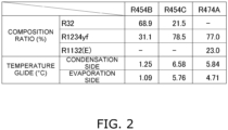
- FIG. 2 is a table showing the composition ratio and the temperature glide of the non-azeotropic mixed refrigerant used in the present embodiment. Physical property values of R454B, R454C, and R474A are determined on the basis of the composition ratio shown in FIG. 2 .
- the operation of the air conditioner 1 will be described by taking the cooling operation and the heating operation as examples.
- the four-way switching valve 13 is maintained in a state indicated by solid lines in FIG. 1 .
- the high-temperature and high-pressure gas refrigerant discharged from the compressor 11 flows into the outdoor heat exchanger 15 via the four-way switching valve 13, and exchanges heat with outdoor air to be condensed.
- the condensed refrigerant flows into the liquid pipe 19a of the liquid gas heat exchanger 19 through the first connection point S1, the check valve 17b, and the fourth connection point S4 of the bridge circuit unit 17.
- the refrigerant flowing through the liquid pipe 19a exchanges heat with the refrigerant flowing through the gas pipe 19b to be subcooled.
- the refrigerant having flowed through the liquid pipe 19a is temporarily stored in the high-pressure receiver 21.
- the refrigerant flowing out of the high-pressure receiver 21 is decompressed to a predetermined low pressure in the expansion valve 23.
- the refrigerant decompressed by the expansion valve 23 flows into the indoor heat exchanger 35 through the second connection point S2, the check valve 17c, and the third connection point S3 of the bridge circuit unit 17.
- the refrigerant exchanges heat with the indoor air in the indoor heat exchanger 35 and evaporates.
- the indoor air cooled by the evaporation of the refrigerant is blown into an indoor space by the corresponding indoor fan 37 to cool the indoor space.
- the refrigerant flowing through the gas pipe 19b exchanges heat with the refrigerant flowing through the liquid pipe 19a to become superheated steam.
- the refrigerant having flowed through the gas pipe 19b is sucked into the compressor 11 through the accumulator 27.
- the indoor air heated by the heat exchange with the refrigerant is blown into the indoor space by the indoor fan 37 to heat the indoor space.
- the refrigerant condensed in the indoor heat exchanger 35 flows through the liquid refrigerant pipe 5 to reach the bridge circuit unit 17.
- the refrigerant flows into the liquid pipe 19a of the liquid gas heat exchanger 19 through the third connection point S3, the check valve 17d, and the fourth connection point S4 of the bridge circuit unit 17.
- the refrigerant flowing through the liquid pipe 19a exchanges heat with the refrigerant flowing through the gas pipe 19b to be subcooled.
- the refrigerant having flowed through the liquid pipe 19a is temporarily stored in the high-pressure receiver 21.
- the refrigerant flowing out of the high-pressure receiver 21 is decompressed to a predetermined low pressure by the expansion valve 23.
- the decompressed refrigerant flows into the outdoor heat exchanger 15 through the second connection point S2, the check valve 17a, and the first connection point S1 of the bridge circuit unit 17.
- the refrigerant exchanges heat with the outdoor air in the outdoor heat exchanger 15 and evaporates.
- the refrigerant evaporated in the outdoor heat exchanger 15 flows into the gas pipe 19b of the liquid gas heat exchanger 19 through the four-way switching valve 13.
- the refrigerant flowing through the gas pipe 19b exchanges heat with the refrigerant flowing through the liquid pipe 19a to become superheated steam.
- the refrigerant having flowed through the gas pipe 19b is sucked into the compressor 11 through the accumulator 27.
- the refrigerant is filled after the outdoor unit 20 and the indoor unit 30 are connected via the liquid refrigerant pipe 5 and the gas refrigerant pipe 6 at the installation location of the air conditioner 1.
- the lengths of the liquid refrigerant pipe 5 and the gas refrigerant pipe 6 are determined in accordance with the installation positions of the outdoor unit 20 and the indoor unit 30.
- the air conditioner 1 according to the present embodiment, a non-azeotropic mixed refrigerant is used, and there is a high risk that the composition ratio changes at the time of refrigerant filling after installation. Therefore, it is necessary to reduce the risk.
- the heat source circuit 20a of the outdoor unit 20 is filled in advance with an amount of refrigerant corresponding to the required amount of refrigerant in the refrigerant circuit 10 when the liquid refrigerant pipe 5 and the gas refrigerant pipe 6 have the predetermined first length L1.
- the first length L1 is a length that eliminates the need for additionally filling the refrigerant into the refrigerant circuit 10 constituted by connecting the outdoor unit 20 and the indoor unit 30 via the liquid refrigerant pipe 5 and the gas refrigerant pipe 6.
- the first length L1 is set to 30 m.
- the refrigerant is filled in the outdoor heat exchanger 15, the liquid gas heat exchanger 19, the high-pressure receiver 21, the accumulator 27, and the pipes connecting the above included in the heat source circuit 20a of the outdoor unit 20.
- the amount of the non-azeotropic mixed refrigerant filled in advance in the outdoor unit 20 needs to be, for example, two to three times an amount of R32 refrigerant required in the refrigerant circuit 10 as a whole when the refrigerant circuit 10 in which the liquid refrigerant pipe 5 and the gas refrigerant pipe 6 are set to the first length is filled with the R32 refrigerant.
- a pipe diameter in the outdoor unit 20 is made larger than a pipe diameter in the indoor unit 30.
- the volume ratio of the outdoor heat exchanger 15 to the indoor heat exchanger 35 is set to three or more in order that the amount of refrigerant filled in advance in the outdoor unit 20 satisfies the amount of refrigerant required in the refrigerant circuit 10 as a whole.
- the volume ratio of the high-pressure receiver 21 to the outdoor heat exchanger 15 within a range of 0.04 to 0.6, the amount of refrigerant filled in advance in the outdoor unit 20 required in the refrigerant circuit 10 as a whole can be satisfied with a margin.
- the installation work of the air conditioner 1 includes a step of installing the outdoor unit 20 and the indoor unit 30 at installation locations, a step of connecting the outdoor unit 20 and the indoor unit 30 via the liquid refrigerant pipe 5 and the gas refrigerant pipe 6, and a step of sending the refrigerant filled in the outdoor unit 20 to the refrigerant circuit 10.
- the refrigerant circuit 10 is filled by opening the liquid-side shutoff valve 25 and the gas-side shutoff valve 26.
- the outdoor unit 20 and the indoor unit 30 are connected via the liquid refrigerant pipe 5 and the gas refrigerant pipe 6 at the installation locations to constitute the refrigerant circuit 10.
- the refrigerant filled in the refrigerant circuit 10 is a non-azeotropic mixed refrigerant having a temperature glide of 1°C or higher during evaporation and condensation.
- the lengths of the liquid refrigerant pipe 5 and the gas refrigerant pipe 6 are determined in accordance with the installation positions of the outdoor unit 20 and the indoor unit 30.
- the outdoor unit 20 is filled in advance with an amount of refrigerant corresponding to the required amount of refrigerant in the refrigerant circuit 10 when the liquid refrigerant pipe 5 and the gas refrigerant pipe 6 have the first length L1.
- the outdoor unit 20 is filled with the refrigerant in advance to save on-site filling work, and thus, the composition ratio of the non-azeotropic mixed refrigerant can be maintained.
- the liquid refrigerant pipe 5 is desirably a 2.5/8-inch pipe (having an outer diameter of 7.93 mm) or a larger pipe.
- the pipe diameter of the liquid refrigerant pipe 5 needs to be increased, and the filling amount of the refrigerant increases.
- the risk that the composition ratio of the refrigerant changes during filling on site increases. Therefore, in the air conditioner 1, there is a great advantage of filling the outdoor unit 20 with the refrigerant in advance in terms of maintaining the composition ratio of the non-azeotropic mixed refrigerant.
- the amount of the non-azeotropic mixed refrigerant filled in advance in the outdoor unit 20 is two to three times an amount of single R32 refrigerant required in the refrigerant circuit 10 as a whole when the refrigerant circuit 10 in which the lengths of the liquid refrigerant pipe 5 and the gas refrigerant pipe 6 are set to the first length L1 is filled with the R32 refrigerant.
- Some non-azeotropic mixed refrigerants require a filling amount two to three times the amount of R32 refrigerant having a temperature glide of 0, and such a refrigerant has a high risk of changing the composition ratio at the time of on-site filling. Therefore, in the air conditioner 1, there is a great advantage of filling the outdoor unit 20 with the refrigerant in advance in terms of maintaining the composition ratio of the non-azeotropic mixed refrigerant.
- the volume ratio of the outdoor heat exchanger 15 to the indoor heat exchanger 35 is three or more. As a result, the amount of refrigerant filled in advance in the outdoor unit 20 can satisfy the amount of refrigerant required in the refrigerant circuit 10 as a whole.
- the high-pressure receiver 21 is connected between the outdoor heat exchanger 15 and the expansion valve 23.
- the volume ratio of the high-pressure receiver 21 to the outdoor heat exchanger 15 is in a range of 0.04 to 0.6.
- the amount of refrigerant corresponding to an internal volume of the high-pressure receiver 21 can be included in the amount of refrigerant that can be filled in advance in the outdoor unit 20.
- the refrigerant circuit 10 is provided with the liquid gas heat exchanger 19 that causes heat exchange between a high-pressure liquid refrigerant and a low-pressure gas refrigerant.
- the liquid gas heat exchanger 19 is a double pipe heat exchanger.
- the amount of refrigerant corresponding to an internal volume of the liquid gas heat exchanger 19 can be included in the amount of refrigerant that can be filled in advance in the outdoor unit 20.
- a worker who performs installation work of the air conditioner 1 determines whether the lengths of the liquid refrigerant pipe 5 and the gas refrigerant pipe 6 required for the installation work of the air conditioner 1 are equal to or less than the first length L1.
- the refrigerant filled in the outdoor unit 20 is equal to or more than the required amount of refrigerant, and thus, a step of additionally filling the refrigerant is unnecessary. Therefore, after the outdoor unit 20 and the indoor unit 30 are connected via the liquid refrigerant pipe 5 and the gas refrigerant pipe 6 without performing the step of additionally filling the refrigerant, the installation work ends.
- the amount of refrigerant filled in the outdoor unit 20 is equal to or more than the required amount of refrigerant in the refrigerant circuit 10 when the lengths of the liquid refrigerant pipe 5 and the gas refrigerant pipe 6 are equal to or less than the first length L1.
- the refrigerant filled in advance in the outdoor unit 20 is insufficient for the required amount of refrigerant, and thus the step of additionally filling the refrigerant is necessary.
- the step of additionally filling the refrigerant is performed, and the refrigerant circuit 10 is additionally filled with an amount of refrigerant corresponding to the lengths of the liquid refrigerant pipe 5 and the gas refrigerant pipe 6.
- the refrigerant is additionally filled, for example, from a service port of the liquid-side shutoff valve 25 or the gas-side shutoff valve 26.
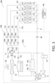
- FIG. 3 is a circuit diagram of a refrigerant circuit 110 of an air conditioner 100 according to a second embodiment of the present disclosure.
- the air conditioner 100 is a multi-chamber air conditioner, and a plurality of indoor units 30a, 30b, 30c, and 30d as utilization units are connected in parallel to one outdoor unit 120 as a heat source unit.
- the compressor 11, the four-way switching valve 13, the outdoor heat exchanger 15, the bridge circuit unit 17, the liquid gas heat exchanger 19, the high-pressure receiver 21, the expansion valve 23, and the accumulator 27 are provided in the flow path of the refrigerant from liquid-side shutoff valves 25a, 25b, 25c, and 25d to the gas-side shutoff valve 26, and constitute a heat source circuit 120a as a part of the refrigerant circuit 10.
- the compressor 11, the four-way switching valve 13, the outdoor heat exchanger 15, the bridge circuit unit 17, the liquid gas heat exchanger 19, the high-pressure receiver 21, the expansion valve 23, and the refrigerant to be filled are common to those in the first embodiment, and thus will not be described.
- second expansion valves 24a, 24b, 24c, and 24d are connected in parallel.
- the second expansion valves 24a, 24b, 24c, and 24d are connected in series to the corresponding liquid-side shutoff valves 25a, 25b, 25c, and 25d.
- the liquid-side shutoff valves 25a, 25b, 25c, and 25d are connected in series to the corresponding second expansion valves 24a, 24b, 24c, and 24d between the corresponding second expansion valves 24a, 24b, 24c, and 24d and corresponding indoor heat exchangers 35a, 35b, 35c, and 35d.
- liquid-side shutoff valves 25a, 25b, 25c, and 25d and the corresponding indoor heat exchangers 35a, 35b, 35c, and 35d are connected by corresponding liquid refrigerant pipes 5a, 5b, 5c, and 5d.
- the indoor heat exchangers 35a, 35b, 35c, and 35d are disposed in the indoor units 30a, 30b, 30c, and 30d, respectively.
- Indoor fans 37a, 37b, 37c, and 37d that generate air flows are respectively disposed in the indoor units 30a, 30b, 30c, and 30d to promote heat exchange between air and the indoor heat exchangers 35a, 35b, 35c, and 35d.
- the indoor heat exchangers 35a, 35b, 35c, and 35d are air heat exchangers.
- the indoor heat exchangers 35a, 35b, 35c, and 35d cause heat exchange between the refrigerant flowing inside and the indoor air sent from the corresponding indoor fans 37a, 37b, 37c, and 37d.
- fin-and-tube heat exchangers are employed as the indoor heat exchangers 35a, 35b, 35c, and 35d.
- the indoor heat exchanger 35a has one end connected to the liquid-side shutoff valve 25a via the liquid refrigerant pipe 5a and the other end connected to the gas-side shutoff valve 26.
- the indoor heat exchanger 35b has one end connected to the liquid-side shutoff valve 25b via the liquid refrigerant pipe 5b and the other end connected to the gas-side shutoff valve 26 via the gas refrigerant pipe 6.
- the indoor heat exchanger 35c has one end connected to the liquid-side shutoff valve 25c via the liquid refrigerant pipe 5c and the other end connected to the gas-side shutoff valve 26 via the gas refrigerant pipe 6.
- the indoor heat exchanger 35d has one end connected to the liquid-side shutoff valve 25d via the liquid refrigerant pipe 5d and the other end connected to the gas-side shutoff valve 26 via the gas refrigerant pipe 6.
- the indoor fans 37a, 37b, 37c, and 37d generate an air flow to promote heat exchange between the refrigerant flowing inside the corresponding indoor heat exchangers 35a, 35b, 35c, and 35d and air.
- the indoor fans 37a, 37b, 37c, and 37d are sirocco fans.
- the liquid refrigerant pipes 5a, 5b, 5c, and 5d and the gas refrigerant pipe 6 connect the outdoor unit 120 and the indoor units 30a, 30b, 30c, and 30d to constitute the refrigerant circuit 110.
- the lengths of the liquid refrigerant pipes 5a, 5b, 5c, and 5d and the gas refrigerant pipe 6 are determined in accordance with the installation positions of the outdoor unit 120 and the indoor units 30a, 30b, 30c, and 30d.
- the liquid refrigerant pipes 5a, 5b, 5c, and 5d link the corresponding liquid-side shutoff valves 25a, 25b, 25c, and 25d of the outdoor unit 120 and refrigerant inlets of the corresponding indoor heat exchangers 35a, 35b, 35c, and 35d during the cooling operation (refrigerant outlets during the heating operation).
- the gas refrigerant pipe 6 connects the gas-side shutoff valve 26 of the outdoor unit 120 and the refrigerant outlet of the indoor heat exchangers 35a, 35b, 35d, and 35c during the cooling operation (the refrigerant inlet during the heating operation).
- the pipe diameters of the liquid refrigerant pipes 5a, 5b, 5c, and 5d need to be increased, and 2.5/8-inch pipes (having an outer diameter of 7.93 mm) or larger pipes are desirable.
- the filling amount of the refrigerant increases, and as the filling amount increases, the risk that the composition ratio of the refrigerant changes during filling on site increases. Therefore, in the air conditioner 100, there is a great advantage of filling the outdoor unit 120 with the refrigerant in advance in terms of maintaining the composition ratio of the non-azeotropic mixed refrigerant.
- the control unit 40 controls the operating frequency of compressor 11, switching of the four-way switching valve 13, the opening degree of the expansion valve 23, an opening degree of second expansion valves 24a, 24b, 24c, and 24d, and the like.
- the control unit 40 includes a printed circuit board equipped with a microprocessor and a memory.
- the operation of the air conditioner 100 will be described by taking the cooling operation and the heating operation as examples.
- the four-way switching valve 13 is maintained in a state indicated by solid lines in FIG. 3 .
- the expansion valve 23 is controlled such that a valve opening degree is fully opened.
- the high-temperature and high-pressure gas refrigerant discharged from the compressor 11 flows into the outdoor heat exchanger 15 via the four-way switching valve 13, and exchanges heat with outdoor air to be condensed.
- the condensed refrigerant flows into the liquid pipe 19a of the liquid gas heat exchanger 19 through the first connection point S1, the check valve 17b, and the fourth connection point S4 of the bridge circuit unit 17.
- the refrigerant flowing through the liquid pipe 19a exchanges heat with the refrigerant flowing through the gas pipe 19b to be subcooled.
- the refrigerant having flowed through the liquid pipe 19a is temporarily stored in the high-pressure receiver 21. Then, the refrigerant flowing out of the high-pressure receiver 21 passes through the expansion valve 23 that is fully opened, and is distributed to the second expansion valves 24a, 24b, 24c, and 24d through the second connection point S2, the check valve 17c, and the third connection point S3 of the bridge circuit unit 17, and is decompressed to a predetermined low pressure.
- the refrigerant decompressed by the second expansion valves 24a, 24b, 24c, and 24d exchanges heat with indoor air in the corresponding indoor heat exchangers 35a, 35b, 35c, and 35d, and evaporates.
- the indoor air cooled by the evaporation of the refrigerant is blown into the indoor space by the corresponding indoor fans 37a, 37b, 37c, and 37d to cool the indoor space.
- the refrigerant evaporated in the indoor heat exchangers 35a, 35b, 35c, and 35d merges in the gas refrigerant pipe 6 and flows into the gas pipe 19b of the liquid gas heat exchanger 19 through the four-way switching valve 13.
- the refrigerant flowing through the gas pipe 19b exchanges heat with the refrigerant flowing through the liquid pipe 19a to become superheated steam.
- the refrigerant having flowed through the gas pipe 19b is sucked into the compressor 11 through the accumulator 27.
- the four-way switching valve 13 is maintained in a state indicated by broken lines in FIG. 3 .
- the second expansion valve 24a, 24b, 24c, and 24d are controlled such that each valve opening degree is fully opened.
- the high-temperature and high-pressure gas refrigerant discharged from the compressor 11 flows into each of the indoor heat exchangers 35a, 35b, 35c, and 35d via the four-way switching valve 13, and exchanges heat with the indoor air to be condensed.
- the indoor air heated by the heat exchange with the refrigerant is blown into the indoor space by the corresponding indoor fans 37a, 37b, 37c, and 37d to heat the indoor space.
- the refrigerant condensed in the indoor heat exchangers 35a, 35b, 35c, and 35d flows to the corresponding liquid refrigerant pipes 5a, 5b, 5c, and 5d, and reaches the corresponding second expansion valves 24a, 24b, 24c, and 24d. Since the valve opening degrees of the second expansion valves 24a, 24b, 24c, and 24d are fully opened, the refrigerant passes through the second expansion valves 24a, 24b, 24c, and 24d and merges without being decompressed.
- the refrigerant flows into the liquid pipe 19a of the liquid gas heat exchanger 19 through the third connection point S3, the check valve 17d, and the fourth connection point S4 of the bridge circuit unit 17.
- the refrigerant flowing through the liquid pipe 19a exchanges heat with the refrigerant flowing through the gas pipe 19b to be subcooled.
- the refrigerant having flowed through the liquid pipe 19a is temporarily stored in the high-pressure receiver 21.
- the refrigerant flowing out of the high-pressure receiver 21 is decompressed to a predetermined low pressure by the expansion valve 23.
- the decompressed refrigerant flows into the outdoor heat exchanger 15 through the second connection point S2, the check valve 17a, and the first connection point S1 of the bridge circuit unit 17.
- the refrigerant exchanges heat with the outdoor air in the outdoor heat exchanger 15 and evaporates.
- the refrigerant evaporated in the outdoor heat exchanger 15 flows into the gas pipe 19b of the liquid gas heat exchanger 19 through the four-way switching valve 13.
- the refrigerant flowing through the gas pipe 19b exchanges heat with the refrigerant flowing through the liquid pipe 19a to become superheated steam.
- the refrigerant having flowed through the gas pipe 19b is sucked into the compressor 11 through the accumulator 27.
- the refrigerant is filled after the outdoor unit 120 and the indoor units 30a, 30b, 30c, and 30d are connected via the liquid refrigerant pipes 5a, 5b, 5c, and 5d and the gas refrigerant pipe 6 at the installation location of the air conditioner 100.
- the lengths of the liquid refrigerant pipes 5a, 5b, 5c, and 5d and the gas refrigerant pipe 6 are determined in accordance with the installation positions of the outdoor unit 120 and the indoor units 30a, 30b, 30c, and 30d.
- the air conditioner 100 according to the present embodiment, a non-azeotropic mixed refrigerant is used, and there is a high risk that the composition ratio changes at the time of refrigerant filling after installation. Therefore, it is necessary to reduce the risk.
- the heat source circuit 120a of the outdoor unit 120 is filled in advance with an amount of refrigerant corresponding to the required refrigerant amount in the refrigerant circuit 110 when the liquid refrigerant pipes 5a, 5b, 5c, and 5d and the gas refrigerant pipe 6 have the predetermined first length L1.
- the first length L1 is a length that eliminates the need for additionally filling the refrigerant into the refrigerant circuit 110 constituted by connecting the outdoor unit 120 and the indoor units 30a, 30b, 30c, and 30d via the liquid refrigerant pipes 5a, 5b, 5c, and 5d and the gas refrigerant pipe 6.
- the first length L1 is set to 30 m.
- the refrigerant is filled in the outdoor heat exchanger 15, the liquid gas heat exchanger 19, the high-pressure receiver 21, the accumulator 27, and the pipes connecting the above included in the heat source circuit 120a of the outdoor unit 120.
- the amount of the non-azeotropic mixed refrigerant filled in advance in the outdoor unit 120 needs to be, for example, two to three times an amount of R32 refrigerant required in the refrigerant circuit 110 as a whole when the refrigerant circuit 110 in which the liquid refrigerant pipes 5a, 5b, 5c, and 5d and the gas refrigerant pipe 6 are set to the first length is filled with the R32 refrigerant.
- a pipe diameter in the outdoor unit 120 is made larger than pipe diameters in the indoor units 30a, 30b, 30c, and 30d.
- the volume ratio of the high-pressure receiver 21 to the outdoor heat exchanger 15 within a range of 0.04 to 0.6, the amount of refrigerant filled in advance in the outdoor unit 120 required in the refrigerant circuit 110 as a whole can be satisfied with a margin.
- the installation work of the air conditioner 100 includes a step of installing the outdoor unit 120 and the indoor units 30a, 30b, 30c, and 30d at installation locations, a step of connecting the outdoor unit 120 and the indoor units 30a, 30b, 30c, and 30d via the liquid refrigerant pipes 5a, 5b, 5c, and 5d and the gas refrigerant pipe 6, and a step of sending the refrigerant filled in the outdoor unit 120 to the refrigerant circuit 110.
- the refrigerant circuit 110 is filled by opening the liquid-side shutoff valves 25a, 25b, 25c, and 25d and the gas-side shutoff valve 26.
- the outdoor unit 120 is filled in advance with an amount of refrigerant corresponding to the required amount of refrigerant in the refrigerant circuit 110 when the liquid refrigerant pipes 5a,5b, 5c, and 5d and the gas refrigerant pipe 6 have the first length L1.
- the outdoor unit 120 is filled with the refrigerant in advance to save on-site filling work, and thus, the composition ratio of the non-azeotropic mixed refrigerant can be maintained.
- the liquid refrigerant pipes 5a, 5b, 5c, and 5d are desirably 2.5/8-inch pipes (having an outer diameter of 7.93 mm) or larger pipes.
- the pipe diameters of the liquid refrigerant pipes 5a, 5b, 5c, and 5d need to be increased, and the filling amount of the refrigerant increases.
- the risk that the composition ratio of the refrigerant changes during filling on site increases. Therefore, in the air conditioner 100, there is a great advantage of filling the outdoor unit 120 with the refrigerant in advance in terms of maintaining the composition ratio of the non-azeotropic mixed refrigerant.
- the amount of the non-azeotropic mixed refrigerant filled in advance in the outdoor unit 120 is two to three times an amount of single R32 refrigerant required in the refrigerant circuit 110 as a whole when the refrigerant circuit 110 in which the lengths of the liquid refrigerant pipe 5 and the gas refrigerant pipe 6 are set to the first length L1 is filled with the R32 refrigerant.
- Some non-azeotropic mixed refrigerants require a filling amount two to three times the amount of R32 refrigerant having a temperature glide of 0, and such a refrigerant has a high risk of changing the composition ratio at the time of on-site filling. Therefore, in the air conditioner 100, there is a great advantage of filling the outdoor unit 120 with the refrigerant in advance in terms of maintaining the composition ratio of the non-azeotropic mixed refrigerant.
- the volume ratio of the outdoor heat exchanger 15 to the total volume of the indoor heat exchangers 35a, 35b, 35c, and 35d is three or more.
- the amount of refrigerant filled in advance in the outdoor unit 120 can satisfy the amount of refrigerant required in the refrigerant circuit 110 as a whole.
- the high-pressure receiver 21 is connected between the outdoor heat exchanger 15 and the expansion valve 23.
- the volume ratio of the high-pressure receiver 21 to the outdoor heat exchanger 15 is in a range of 0.04 to 0.6.
- the amount of refrigerant corresponding to an internal volume of the high-pressure receiver 21 can be included in the amount of refrigerant that can be filled in advance in the outdoor unit 120.
- the refrigerant circuit 110 is provided with the liquid gas heat exchanger 19 that causes heat exchange between a high-pressure liquid refrigerant and a low-pressure gas refrigerant.
- the liquid gas heat exchanger 19 is a double pipe heat exchanger.
- the amount of refrigerant corresponding to an internal volume of the liquid gas heat exchanger 19 can be included in the amount of refrigerant that can be filled in advance in the outdoor unit 120.
- a worker who performs installation work of the air conditioner 100 determines whether the lengths of the liquid refrigerant pipes 5a, 5b, 5c, and 5d and the gas refrigerant pipe 6 required for the installation work of the air conditioner 100 are equal to or less than the first length L1.
- the refrigerant filled in the outdoor unit 120 is equal to or more than the required amount of refrigerant, and thus, a step of additionally filling the refrigerant is unnecessary. Therefore, after the outdoor unit 120 and the indoor units 30a, 30b, 30c and 30d are connected via the liquid refrigerant pipes 5a, 5b, 5c, and 5d and the gas refrigerant pipe 6 without performing the step of additionally filling the refrigerant, the installation work ends.
- the amount of refrigerant filled in the outdoor unit 120 is more than the required amount of refrigerant in the refrigerant circuit 110 when the lengths of the liquid refrigerant pipes 5a, 5b, 5c, and 5d and the gas refrigerant pipe 6 are equal to or less than the first length L1.
- the refrigerant filled in advance in the outdoor unit 120 is insufficient for the required amount of refrigerant, and thus the step of additionally filling the refrigerant is necessary.
- the step of additionally filling the refrigerant is performed, and the refrigerant circuit 110 is additionally filled with an amount of refrigerant corresponding to the lengths of the liquid refrigerant pipes 5a, 5b, 5c, and 5d and the gas refrigerant pipe 6.
- the refrigerant is additionally filled, for example, from a service port of the liquid-side shutoff valves 25a, 25b, 25c, and 25d or the gas-side shutoff valve 26.
- Patent Literature 1 WO 2013/111180 A
Landscapes
- Engineering & Computer Science (AREA)
- Physics & Mathematics (AREA)
- Mechanical Engineering (AREA)
- Thermal Sciences (AREA)
- General Engineering & Computer Science (AREA)
- Compression-Type Refrigeration Machines With Reversible Cycles (AREA)
Abstract
Description
- The present disclosure relates to a heat source unit of an air conditioner using a non-azeotropic mixed refrigerant.
- In a heat pump device using a non-azeotropic mixed refrigerant, there is a risk that the composition ratio changes when the refrigerant is filled on site. In order to reduce such a risk, for example, in a heat pump hot water supply apparatus disclosed in Patent Literature 1 (
WO 2013/111180 A ), a specific refrigeration cycle (second refrigeration cycle) is filled with a refrigerant before shipment from a factory. - However, the refrigeration cycle can be filled with the refrigerant before shipment from the factory because a closed refrigerant circuit is already formed in the factory, and the refrigeration cycle cannot be applied to a split air conditioner in which a refrigerant circuit is formed by connecting a utilization unit and a heat source unit with a pipe at an installation location.
- Therefore, there is a problem of providing a split air conditioner with a reduced risk that the composition ratio of the non-azeotropic mixed refrigerant changes at the time of installation.
- A heat source unit according to a first aspect is connected to a utilization unit via a pipe at an installation location to constitute a refrigerant circuit. A refrigerant filled in the heat source unit is a non-azeotropic mixed refrigerant having a temperature glide of 1°C or higher during evaporation and condensation. The heat source unit is filled in advance with the refrigerant in an amount required for the refrigerant circuit when a length of the pipe is a first length that eliminates the need for additionally filling the refrigerant circuit with the refrigerant.
- It is not easy to fill the non-azeotropic mixed refrigerant on site in a state where the composition ratio is maintained. Therefore, the heat source unit is filled with the refrigerant in advance to save on-site filling work, and thus, the composition ratio of the non-azeotropic mixed refrigerant can be maintained.
- A heat source unit according to a second aspect is the heat source unit according to the first aspect, in which the utilization unit as one utilization unit is connected to the heat source unit to constitute the refrigerant circuit.
- A heat source unit according to a third aspect is the heat source unit according to the first aspect, in which a plurality of the utilization units are connected in parallel to the heat source unit to constitute the refrigerant circuit.
- A heat source unit according to a fourth aspect is the heat source unit according to any one of the first to third aspects, in which the temperature glide during evaporation and condensation of the refrigerant is 5°C or higher.
- When a non-azeotropic mixed refrigerant having a temperature glide of 5°C or higher among the non-azeotropic mixed refrigerants is used, it is difficult to fill the refrigerant on site in a state where the composition ratio is maintained. Therefore, in the heat source unit, there is a great advantage of filling the heat source unit with the refrigerant in advance in terms of maintaining the composition ratio of the non-azeotropic mixed refrigerant.
- A heat source unit according to a fifth aspect is the heat source unit according to any one of the first to fourth aspects, in which the pipe that is equal to or larger than a 2.5/8-inch pipe (having an outer diameter of 7.93 mm) and through which a liquid refrigerant or a gas-liquid mixed refrigerant flows is connected to the heat source unit.
- When a refrigerant having a large pressure loss among the non-azeotropic mixed refrigerants is used, the pipe diameter of the pipe through which a liquid refrigerant or a gas-liquid mixed refrigerant flows needs to be increased, and the filling amount of the refrigerant increases. As the filling amount increases, the risk that the composition ratio of the refrigerant changes during filling on site increases. Therefore, in the heat source unit, there is a great advantage of filling the heat source unit with the refrigerant in advance in terms of maintaining the composition ratio of the non-azeotropic mixed refrigerant.
- A heat source unit according to a sixth aspect is the heat source unit according to the fifth aspect, in which the pipe through which the liquid refrigerant or the gas-liquid mixed refrigerant flows is a 2.5/8-inch pipe (having an outer diameter of 7.93 mm).
- When an actual length of the pipe exceeds the first length, the refrigerant needs to be additionally filled, which increases the risk of a change in the composition ratio of the refrigerant. In order to reduce the risk of a change in the composition ratio in such a situation, a 2.5/8-inch pipe is suitable as the pipe through which the liquid refrigerant or the gas-liquid mixed refrigerant flows from both viewpoints of "reduction of pressure loss" and "reduction of an additional refrigerant filling amount".
- A heat source unit according to a seventh aspect is the heat source unit according to any one of the first to sixth aspects, in which an amount of the refrigerant filled in advance in the heat source unit is two to three times an amount of an R32 refrigerant required in the refrigerant circuit as a whole when the refrigerant circuit in which the length of the pipe is set to the first length is filled with the R32 refrigerant.
- Some non-azeotropic mixed refrigerants require a filling amount two to three times the amount of R32 refrigerant having a temperature glide of 0, and such a refrigerant has a high risk of changing the composition ratio at the time of on-site filling. Therefore, in the heat source unit, there is a great advantage of filling the heat source unit with the refrigerant in advance in terms of maintaining the composition ratio of the non-azeotropic mixed refrigerant.
- A heat source unit according to an eighth aspect is the heat source unit according to any one of the first to seventh aspects, in which the first length is 30 m.
- A heat source unit according to a ninth aspect is the heat source unit according to any one of the first to eighth aspects, and includes a first shutoff valve, a second shutoff valve, and a heat source circuit. The heat source circuit is a flow path of the refrigerant from the first shutoff valve to the second shutoff valve, and constitutes a part of the refrigerant circuit. The heat source circuit includes a compressor, a heat exchanger, and a decompressor. The compressor, the heat exchanger, and the decompressor are connected in order. The heat source circuit further includes a high-pressure receiver connected between the heat exchanger and the decompressor.
- The amount of refrigerant corresponding to an internal volume of the high-pressure receiver can be included in the amount of refrigerant that can be filled in advance in the heat source unit.
- A heat source unit according to a tenth aspect is the heat source unit according to the ninth aspect, in which a volume ratio of the high-pressure receiver to the heat exchanger is in a range of 0.04 to 0.6.
-
-
FIG. 1 is a circuit diagram of a refrigerant circuit of an air conditioner according to a first embodiment of the present disclosure. -
FIG. 2 is a table showing a composition ratio and a temperature glide of a non-azeotropic mixed refrigerant used in the present embodiment. -
FIG. 3 is a circuit diagram of a refrigerant circuit of an air conditioner according to a second embodiment of the present disclosure. -
FIG. 1 is a circuit diagram of arefrigerant circuit 10 of an air conditioner 1 according to a first embodiment of the present disclosure. In the air conditioner 1, oneindoor unit 30 as a utilization unit is connected to oneoutdoor unit 20 as a heat source unit via a liquid refrigerant pipe 5 and agas refrigerant pipe 6. - The refrigerant filled in the
refrigerant circuit 10 is a non-azeotropic mixed refrigerant having a temperature glide of 1°C or higher during evaporation and condensation. Usually, the refrigerant is filled after theoutdoor unit 20 and theindoor unit 30 are connected via the liquid refrigerant pipe 5 and thegas refrigerant pipe 6 at the installation location of the air conditioner 1. - However, in the present embodiment, the
outdoor unit 20 before the liquid refrigerant pipe 5 and thegas refrigerant pipe 6 are connected is filled in advance with the refrigerant in an amount required in therefrigerant circuit 10 as a whole when the lengths of the liquid refrigerant pipe 5 and thegas refrigerant pipe 6 are set to a predetermined first length L1 regardless of the actual lengths of the liquid refrigerant pipe 5 and thegas refrigerant pipe 6. - The
outdoor unit 20 includes acompressor 11, a four-way switching valve 13, anoutdoor heat exchanger 15, abridge circuit unit 17, a liquidgas heat exchanger 19, a high-pressure receiver 21, anexpansion valve 23, a liquid-side shutoff valve 25, a gas-side shutoff valve 26, and anaccumulator 27. - The
compressor 11, the four-way switching valve 13, theoutdoor heat exchanger 15, thebridge circuit unit 17, the liquidgas heat exchanger 19, the high-pressure receiver 21, theexpansion valve 23, and theaccumulator 27 are provided in a refrigerant flow path from the liquid-side shutoff valve 25 to the gas-side shutoff valve 26, and constitute aheat source circuit 20a that is a part of therefrigerant circuit 10. - In the
outdoor unit 20, anoutdoor fan 29 that generates an air flow is disposed to promote heat exchange between air and theoutdoor heat exchanger 15. - The
compressor 11 includes a suction port 11a and adischarge port 11b. The refrigerant flows into thecompressor 11 through the suction port 11a, is compressed to have a high temperature and a high pressure, and flows out from thedischarge port 11b. - The four-
way switching valve 13 includes a first port P1, a second port P2, a third port P3, and a fourth port P4. The first port P1 is linked to thedischarge port 11b of thecompressor 11. The second port P2 is linked to theoutdoor heat exchanger 15. The third port P3 is linked to the suction port 11a of thecompressor 11 via the liquidgas heat exchanger 19 and theaccumulator 27. The fourth port P4 is linked to the gas-side shutoff valve 26. - The
outdoor heat exchanger 15 is an air heat exchanger. Theoutdoor heat exchanger 15 causes heat exchange between the refrigerant flowing inside and outside air sent from theoutdoor fan 29. In the present embodiment, a fin-and-tube heat exchanger is employed as theoutdoor heat exchanger 15. - In the
bridge circuit unit 17, fourcheck valves check valve 17a and thecheck valve 17b is linked to theoutdoor heat exchanger 15. A second connection point S2 between thecheck valve 17a and thecheck valve 17c is linked to theexpansion valve 23. A third connection point S3 between thecheck valve 17c and thecheck valve 17d is linked to the liquid-side shutoff valve 25. Furthermore, a fourth connection point S4 between thecheck valve 17b and thecheck valve 17d is linked to aliquid pipe 19a of the liquidgas heat exchanger 19. - The liquid
gas heat exchanger 19 causes heat exchange between a high-pressure refrigerant flowing through theliquid pipe 19a and a low-pressure refrigerant flowing through agas pipe 19b. The liquidgas heat exchanger 19 is a double pipe heat exchanger. - The high-
pressure receiver 21 temporarily stores the refrigerant subcooled by the liquidgas heat exchanger 19. - The
expansion valve 23 is disposed between an outlet of the high-pressure receiver 21 and the second connection point S2 of thebridge circuit unit 17. Theexpansion valve 23 decompresses the refrigerant flowing from the high-pressure receiver 21 toward the second connection point S2 of thebridge circuit unit 17 to a predetermined low pressure. - The liquid-
side shutoff valve 25 is connected between the third connection point S3 of thebridge circuit unit 17 and anindoor heat exchanger 35. The liquid-side shutoff valve 25 and theindoor heat exchanger 35 are connected by the liquid refrigerant pipe 5. - The gas-
side shutoff valve 26 is connected in series with the four-way switching valve 13 between the four-way switching valve 13 and theindoor heat exchanger 35. The gas-side shutoff valve 26 and theindoor heat exchanger 35 are connected by thegas refrigerant pipe 6. - The
accumulator 27 is connected between the four-way switching valve 13 and the suction port 11a of thecompressor 11. The accumulator 24 collects a liquid refrigerant that has not been gasified in an evaporator, and prevents the liquid refrigerant from flowing into the suction port 11a of thecompressor 11. - The
outdoor fan 29 generates an air flow to promote heat exchange between the refrigerant flowing in theoutdoor heat exchanger 15 and air. Theoutdoor fan 29 is a propeller fan. - The
indoor heat exchanger 35 is disposed in theindoor unit 30. Anindoor fan 37 that generates an air flow is disposed in theindoor unit 30 to promote heat exchange between air and theindoor heat exchanger 35. - The
indoor heat exchanger 35 is an air heat exchanger. Theindoor heat exchanger 35 causes heat exchange between the refrigerant flowing inside and indoor air sent from theindoor fan 37. In the present embodiment, a fin-and-tube heat exchanger is employed as theindoor heat exchanger 35. - The
indoor heat exchanger 35 has one end connected to the liquid-side shutoff valve 25 via the liquid refrigerant pipe 5 and the other end connected to the gas-side shutoff valve 26 via thegas refrigerant pipe 6. - The
indoor fan 37 generates an air flow to promote heat exchange between the refrigerant flowing inside theindoor heat exchanger 35 and the indoor air. Theindoor fan 37 is a sirocco fan. - The liquid refrigerant pipe 5 and the
gas refrigerant pipe 6 connect theoutdoor unit 20 and theindoor unit 30 to constitute therefrigerant circuit 10. The lengths of the liquid refrigerant pipe 5 and thegas refrigerant pipe 6 are determined in accordance with the installation positions of theoutdoor unit 20 and theindoor unit 30. - The liquid refrigerant pipe 5 links the liquid-
side shutoff valve 25 of theoutdoor unit 20 and a refrigerant inlet of theindoor heat exchanger 35 of theindoor unit 30 during a cooling operation (a refrigerant outlet during a heating operation). - The
gas refrigerant pipe 6 links the gas-side shutoff valve 26 of theoutdoor unit 20 and the refrigerant outlet of theindoor heat exchanger 35 of theindoor unit 30 during the cooling operation (the refrigerant inlet during the heating operation). - When a refrigerant having a large pressure loss among the non-azeotropic mixed refrigerants is used, the pipe diameter of the liquid refrigerant pipe 5 needs to be increased, and a 2.5/8-inch pipe (having an outer diameter of 7.93 mm) or a larger pipe is desirable. However, the filling amount of the refrigerant increases, and as the filling amount increases, the risk that the composition ratio of the refrigerant changes during filling on site increases. Therefore, in the air conditioner 1, there is a great advantage of filling the
outdoor unit 20 with the refrigerant in advance in terms of maintaining the composition ratio of the non-azeotropic mixed refrigerant. - However, when the actual pipe length of the liquid refrigerant pipe 5 and the actual pipe length of the
gas refrigerant pipe 6 exceed the first length L1, the refrigerant needs to be additionally filled, which increases the risk of a change in the composition ratio of the refrigerant. In order to reduce the risk of a change in the composition ratio in such a situation, in the air conditioner 1, a 2.5/8-inch pipe is suitable as the liquid refrigerant pipe 5 from both viewpoints of "suppression of pressure loss" and "suppression of an additional refrigerant filling amount". - A
control unit 40 controls an operating frequency of thecompressor 11, switching of the four-way switching valve 13, an opening degree of theexpansion valve 23, and the like. Thecontrol unit 40 includes a printed circuit board equipped with a microprocessor and a memory. - The refrigerant used in the present embodiment is a non-azeotropic mixed refrigerant. In the non-azeotropic mixed refrigerant, two or more refrigerants having different boiling points are mixed. Since the refrigerant having a higher boiling point condenses earlier than the refrigerant having a lower boiling point, the isotherm of the non-azeotropic mixed refrigerant goes down to the right from the saturated liquid line toward the saturated vapor line. Therefore, temperature glide is generated in the saturated liquid line and the saturated vapor line under the same pressure condition.
-
FIG. 2 is a table showing the composition ratio and the temperature glide of the non-azeotropic mixed refrigerant used in the present embodiment. Physical property values of R454B, R454C, and R474A are determined on the basis of the composition ratio shown inFIG. 2 . - Here, the operation of the air conditioner 1 will be described by taking the cooling operation and the heating operation as examples.
- During the cooling operation, the four-
way switching valve 13 is maintained in a state indicated by solid lines inFIG. 1 . The high-temperature and high-pressure gas refrigerant discharged from thecompressor 11 flows into theoutdoor heat exchanger 15 via the four-way switching valve 13, and exchanges heat with outdoor air to be condensed. - The condensed refrigerant flows into the
liquid pipe 19a of the liquidgas heat exchanger 19 through the first connection point S1, thecheck valve 17b, and the fourth connection point S4 of thebridge circuit unit 17. The refrigerant flowing through theliquid pipe 19a exchanges heat with the refrigerant flowing through thegas pipe 19b to be subcooled. - The refrigerant having flowed through the
liquid pipe 19a is temporarily stored in the high-pressure receiver 21. The refrigerant flowing out of the high-pressure receiver 21 is decompressed to a predetermined low pressure in theexpansion valve 23. The refrigerant decompressed by theexpansion valve 23 flows into theindoor heat exchanger 35 through the second connection point S2, thecheck valve 17c, and the third connection point S3 of thebridge circuit unit 17. The refrigerant exchanges heat with the indoor air in theindoor heat exchanger 35 and evaporates. The indoor air cooled by the evaporation of the refrigerant is blown into an indoor space by the correspondingindoor fan 37 to cool the indoor space. - The refrigerant evaporated in the
indoor heat exchanger 35 flows into thegas pipe 19b of the liquidgas heat exchanger 19 through thegas refrigerant pipe 6 and the four-way switching valve 13. - The refrigerant flowing through the
gas pipe 19b exchanges heat with the refrigerant flowing through theliquid pipe 19a to become superheated steam. The refrigerant having flowed through thegas pipe 19b is sucked into thecompressor 11 through theaccumulator 27. - During the heating operation, the four-
way switching valve 13 is maintained in a state indicated by broken lines inFIG. 1 . The high-temperature and high-pressure gas refrigerant discharged from thecompressor 11 flows into theindoor heat exchanger 35 via the four-way switching valve 13, and exchanges heat with the indoor air to be condensed. - The indoor air heated by the heat exchange with the refrigerant is blown into the indoor space by the
indoor fan 37 to heat the indoor space. - The refrigerant condensed in the
indoor heat exchanger 35 flows through the liquid refrigerant pipe 5 to reach thebridge circuit unit 17. The refrigerant flows into theliquid pipe 19a of the liquidgas heat exchanger 19 through the third connection point S3, thecheck valve 17d, and the fourth connection point S4 of thebridge circuit unit 17. The refrigerant flowing through theliquid pipe 19a exchanges heat with the refrigerant flowing through thegas pipe 19b to be subcooled. - The refrigerant having flowed through the
liquid pipe 19a is temporarily stored in the high-pressure receiver 21. The refrigerant flowing out of the high-pressure receiver 21 is decompressed to a predetermined low pressure by theexpansion valve 23. The decompressed refrigerant flows into theoutdoor heat exchanger 15 through the second connection point S2, thecheck valve 17a, and the first connection point S1 of thebridge circuit unit 17. The refrigerant exchanges heat with the outdoor air in theoutdoor heat exchanger 15 and evaporates. - The refrigerant evaporated in the
outdoor heat exchanger 15 flows into thegas pipe 19b of the liquidgas heat exchanger 19 through the four-way switching valve 13. The refrigerant flowing through thegas pipe 19b exchanges heat with the refrigerant flowing through theliquid pipe 19a to become superheated steam. The refrigerant having flowed through thegas pipe 19b is sucked into thecompressor 11 through theaccumulator 27. - Usually, the refrigerant is filled after the
outdoor unit 20 and theindoor unit 30 are connected via the liquid refrigerant pipe 5 and thegas refrigerant pipe 6 at the installation location of the air conditioner 1. The lengths of the liquid refrigerant pipe 5 and thegas refrigerant pipe 6 are determined in accordance with the installation positions of theoutdoor unit 20 and theindoor unit 30. - However, in the air conditioner 1 according to the present embodiment, a non-azeotropic mixed refrigerant is used, and there is a high risk that the composition ratio changes at the time of refrigerant filling after installation. Therefore, it is necessary to reduce the risk.
- As a result, the
heat source circuit 20a of theoutdoor unit 20 is filled in advance with an amount of refrigerant corresponding to the required amount of refrigerant in therefrigerant circuit 10 when the liquid refrigerant pipe 5 and thegas refrigerant pipe 6 have the predetermined first length L1. The first length L1 is a length that eliminates the need for additionally filling the refrigerant into therefrigerant circuit 10 constituted by connecting theoutdoor unit 20 and theindoor unit 30 via the liquid refrigerant pipe 5 and thegas refrigerant pipe 6. In the present embodiment, the first length L1 is set to 30 m. - The refrigerant is filled in the
outdoor heat exchanger 15, the liquidgas heat exchanger 19, the high-pressure receiver 21, theaccumulator 27, and the pipes connecting the above included in theheat source circuit 20a of theoutdoor unit 20. - The amount of the non-azeotropic mixed refrigerant filled in advance in the
outdoor unit 20 needs to be, for example, two to three times an amount of R32 refrigerant required in therefrigerant circuit 10 as a whole when therefrigerant circuit 10 in which the liquid refrigerant pipe 5 and thegas refrigerant pipe 6 are set to the first length is filled with the R32 refrigerant. - In the present embodiment, in order to increase the amount of refrigerant that can be filled in the
outdoor unit 20 in advance, a pipe diameter in theoutdoor unit 20 is made larger than a pipe diameter in theindoor unit 30. - The volume ratio of the
outdoor heat exchanger 15 to theindoor heat exchanger 35 is set to three or more in order that the amount of refrigerant filled in advance in theoutdoor unit 20 satisfies the amount of refrigerant required in therefrigerant circuit 10 as a whole. - Furthermore, by setting the volume ratio of the high-
pressure receiver 21 to theoutdoor heat exchanger 15 within a range of 0.04 to 0.6, the amount of refrigerant filled in advance in theoutdoor unit 20 required in therefrigerant circuit 10 as a whole can be satisfied with a margin. - The installation work of the air conditioner 1 includes a step of installing the
outdoor unit 20 and theindoor unit 30 at installation locations, a step of connecting theoutdoor unit 20 and theindoor unit 30 via the liquid refrigerant pipe 5 and thegas refrigerant pipe 6, and a step of sending the refrigerant filled in theoutdoor unit 20 to therefrigerant circuit 10. - In the step of sending the refrigerant filled in the
outdoor unit 20 to therefrigerant circuit 10, therefrigerant circuit 10 is filled by opening the liquid-side shutoff valve 25 and the gas-side shutoff valve 26. - (4-1)
In the air conditioner 1, theoutdoor unit 20 and theindoor unit 30 are connected via the liquid refrigerant pipe 5 and thegas refrigerant pipe 6 at the installation locations to constitute therefrigerant circuit 10. The refrigerant filled in therefrigerant circuit 10 is a non-azeotropic mixed refrigerant having a temperature glide of 1°C or higher during evaporation and condensation. The lengths of the liquid refrigerant pipe 5 and thegas refrigerant pipe 6 are determined in accordance with the installation positions of theoutdoor unit 20 and theindoor unit 30. The lengths of the liquid refrigerant pipe 5 and thegas refrigerant pipe 6 are preset with the first length L1(for example, L1=30 m) that eliminates the need for additionally filling therefrigerant circuit 10 with the refrigerant. Theoutdoor unit 20 is filled in advance with an amount of refrigerant corresponding to the required amount of refrigerant in therefrigerant circuit 10 when the liquid refrigerant pipe 5 and thegas refrigerant pipe 6 have the first length L1. - It is not easy to fill the non-azeotropic mixed refrigerant on site in a state where the composition ratio is maintained. Therefore, in the air conditioner 1, the
outdoor unit 20 is filled with the refrigerant in advance to save on-site filling work, and thus, the composition ratio of the non-azeotropic mixed refrigerant can be maintained. - (4-2)
In particular, when R454C having a temperature glide of 5°C or more during evaporation and condensation of the refrigerant is used, it is difficult to fill on site in a state where the composition ratio is maintained. Therefore, in the air conditioner 1, there is a great advantage of filling theoutdoor unit 20 with the refrigerant in advance in terms of maintaining the composition ratio of the non-azeotropic mixed refrigerant. - (4-3)
The liquid refrigerant pipe 5 is desirably a 2.5/8-inch pipe (having an outer diameter of 7.93 mm) or a larger pipe. When a refrigerant having a large pressure loss among the non-azeotropic mixed refrigerants is used, the pipe diameter of the liquid refrigerant pipe 5 needs to be increased, and the filling amount of the refrigerant increases. As the filling amount increases, the risk that the composition ratio of the refrigerant changes during filling on site increases. Therefore, in the air conditioner 1, there is a great advantage of filling theoutdoor unit 20 with the refrigerant in advance in terms of maintaining the composition ratio of the non-azeotropic mixed refrigerant. - However, when the actual pipe length of the liquid refrigerant pipe 5 and the actual pipe length of the
gas refrigerant pipe 6 exceed the first length L1, the refrigerant needs to be additionally filled, which further increases the risk of a change in the composition ratio of the refrigerant. In order to reduce the risk of a change in the composition ratio in such a situation, a 2.5/8-inch pipe is suitable as the liquid refrigerant pipe 5 from both viewpoints of "suppression of pressure loss" and "suppression of an additional refrigerant filling amount". - (4-4)
The amount of the non-azeotropic mixed refrigerant filled in advance in theoutdoor unit 20 is two to three times an amount of single R32 refrigerant required in therefrigerant circuit 10 as a whole when therefrigerant circuit 10 in which the lengths of the liquid refrigerant pipe 5 and thegas refrigerant pipe 6 are set to the first length L1 is filled with the R32 refrigerant. - Some non-azeotropic mixed refrigerants require a filling amount two to three times the amount of R32 refrigerant having a temperature glide of 0, and such a refrigerant has a high risk of changing the composition ratio at the time of on-site filling. Therefore, in the air conditioner 1, there is a great advantage of filling the
outdoor unit 20 with the refrigerant in advance in terms of maintaining the composition ratio of the non-azeotropic mixed refrigerant. - (4-5)
Since the pipe diameter in theoutdoor unit 20 is larger than the pipe diameter in theindoor unit 30, the amount of refrigerant that can be filled in theoutdoor unit 20 in advance can be increased. - (4-6)
The volume ratio of theoutdoor heat exchanger 15 to theindoor heat exchanger 35 is three or more. As a result, the amount of refrigerant filled in advance in theoutdoor unit 20 can satisfy the amount of refrigerant required in therefrigerant circuit 10 as a whole. - (4-7)
The high-pressure receiver 21 is connected between theoutdoor heat exchanger 15 and theexpansion valve 23. The volume ratio of the high-pressure receiver 21 to theoutdoor heat exchanger 15 is in a range of 0.04 to 0.6. The amount of refrigerant corresponding to an internal volume of the high-pressure receiver 21 can be included in the amount of refrigerant that can be filled in advance in theoutdoor unit 20. - (4-8)
Therefrigerant circuit 10 is provided with the liquidgas heat exchanger 19 that causes heat exchange between a high-pressure liquid refrigerant and a low-pressure gas refrigerant. The liquidgas heat exchanger 19 is a double pipe heat exchanger. The amount of refrigerant corresponding to an internal volume of the liquidgas heat exchanger 19 can be included in the amount of refrigerant that can be filled in advance in theoutdoor unit 20. - A worker who performs installation work of the air conditioner 1 determines whether the lengths of the liquid refrigerant pipe 5 and the
gas refrigerant pipe 6 required for the installation work of the air conditioner 1 are equal to or less than the first length L1. - When the lengths of the liquid refrigerant pipe 5 and the
gas refrigerant pipe 6 are equal to or less than the first length L1, the refrigerant filled in theoutdoor unit 20 is equal to or more than the required amount of refrigerant, and thus, a step of additionally filling the refrigerant is unnecessary. Therefore, after theoutdoor unit 20 and theindoor unit 30 are connected via the liquid refrigerant pipe 5 and thegas refrigerant pipe 6 without performing the step of additionally filling the refrigerant, the installation work ends. - In other words, the amount of refrigerant filled in the
outdoor unit 20 is equal to or more than the required amount of refrigerant in therefrigerant circuit 10 when the lengths of the liquid refrigerant pipe 5 and thegas refrigerant pipe 6 are equal to or less than the first length L1. - On the other hand, when the lengths of the liquid refrigerant pipe 5 and the
gas refrigerant pipe 6 exceed the first length L1, the refrigerant filled in advance in theoutdoor unit 20 is insufficient for the required amount of refrigerant, and thus the step of additionally filling the refrigerant is necessary. - Therefore, the step of additionally filling the refrigerant is performed, and the
refrigerant circuit 10 is additionally filled with an amount of refrigerant corresponding to the lengths of the liquid refrigerant pipe 5 and thegas refrigerant pipe 6. The refrigerant is additionally filled, for example, from a service port of the liquid-side shutoff valve 25 or the gas-side shutoff valve 26. -
FIG. 3 is a circuit diagram of arefrigerant circuit 110 of anair conditioner 100 according to a second embodiment of the present disclosure. Theair conditioner 100 is a multi-chamber air conditioner, and a plurality ofindoor units outdoor unit 120 as a heat source unit. - Here, the same names and the same reference signs are given to configurations common to the first embodiment, and description thereof is omitted, and only parts different from those in the first embodiment will be described.
- In the
outdoor unit 120, thecompressor 11, the four-way switching valve 13, theoutdoor heat exchanger 15, thebridge circuit unit 17, the liquidgas heat exchanger 19, the high-pressure receiver 21, theexpansion valve 23, and theaccumulator 27 are provided in the flow path of the refrigerant from liquid-side shutoff valves side shutoff valve 26, and constitute aheat source circuit 120a as a part of therefrigerant circuit 10. - The
compressor 11, the four-way switching valve 13, theoutdoor heat exchanger 15, thebridge circuit unit 17, the liquidgas heat exchanger 19, the high-pressure receiver 21, theexpansion valve 23, and the refrigerant to be filled are common to those in the first embodiment, and thus will not be described. - Four
second expansion valves second expansion valves side shutoff valves - The liquid-
side shutoff valves second expansion valves second expansion valves indoor heat exchangers - The liquid-
side shutoff valves indoor heat exchangers refrigerant pipes - The
indoor heat exchangers indoor units -
Indoor fans indoor units indoor heat exchangers - The
indoor heat exchangers indoor heat exchangers indoor fans indoor heat exchangers - The
indoor heat exchanger 35a has one end connected to the liquid-side shutoff valve 25a via the liquidrefrigerant pipe 5a and the other end connected to the gas-side shutoff valve 26. Theindoor heat exchanger 35b has one end connected to the liquid-side shutoff valve 25b via the liquidrefrigerant pipe 5b and the other end connected to the gas-side shutoff valve 26 via thegas refrigerant pipe 6. The indoor heat exchanger 35c has one end connected to the liquid-side shutoff valve 25c via the liquidrefrigerant pipe 5c and the other end connected to the gas-side shutoff valve 26 via thegas refrigerant pipe 6. Furthermore, theindoor heat exchanger 35d has one end connected to the liquid-side shutoff valve 25d via theliquid refrigerant pipe 5d and the other end connected to the gas-side shutoff valve 26 via thegas refrigerant pipe 6. - The
indoor fans indoor heat exchangers indoor fans - The liquid
refrigerant pipes gas refrigerant pipe 6 connect theoutdoor unit 120 and theindoor units refrigerant circuit 110. The lengths of the liquidrefrigerant pipes gas refrigerant pipe 6 are determined in accordance with the installation positions of theoutdoor unit 120 and theindoor units - The liquid
refrigerant pipes side shutoff valves outdoor unit 120 and refrigerant inlets of the correspondingindoor heat exchangers - The
gas refrigerant pipe 6 connects the gas-side shutoff valve 26 of theoutdoor unit 120 and the refrigerant outlet of theindoor heat exchangers - When a refrigerant having a large pressure loss among the non-azeotropic mixed refrigerants is used, the pipe diameters of the liquid
refrigerant pipes air conditioner 100, there is a great advantage of filling theoutdoor unit 120 with the refrigerant in advance in terms of maintaining the composition ratio of the non-azeotropic mixed refrigerant. - However, when the actual pipe lengths of the liquid
refrigerant pipes gas refrigerant pipe 6 exceed the first length L1, the refrigerant needs to be additionally filled, which increases the risk of a change in the composition ratio of the refrigerant. In order to reduce the risk of a change in the composition ratio in such a situation, in theair conditioner 100, 2.5/8-inch pipes are suitable as the liquidrefrigerant pipes - The
control unit 40 controls the operating frequency ofcompressor 11, switching of the four-way switching valve 13, the opening degree of theexpansion valve 23, an opening degree ofsecond expansion valves control unit 40 includes a printed circuit board equipped with a microprocessor and a memory. - Here, the operation of the
air conditioner 100 will be described by taking the cooling operation and the heating operation as examples. - During the cooling operation, the four-
way switching valve 13 is maintained in a state indicated by solid lines inFIG. 3 . Theexpansion valve 23 is controlled such that a valve opening degree is fully opened. The high-temperature and high-pressure gas refrigerant discharged from thecompressor 11 flows into theoutdoor heat exchanger 15 via the four-way switching valve 13, and exchanges heat with outdoor air to be condensed. - The condensed refrigerant flows into the
liquid pipe 19a of the liquidgas heat exchanger 19 through the first connection point S1, thecheck valve 17b, and the fourth connection point S4 of thebridge circuit unit 17. The refrigerant flowing through theliquid pipe 19a exchanges heat with the refrigerant flowing through thegas pipe 19b to be subcooled. - The refrigerant having flowed through the
liquid pipe 19a is temporarily stored in the high-pressure receiver 21. Then, the refrigerant flowing out of the high-pressure receiver 21 passes through theexpansion valve 23 that is fully opened, and is distributed to thesecond expansion valves check valve 17c, and the third connection point S3 of thebridge circuit unit 17, and is decompressed to a predetermined low pressure. The refrigerant decompressed by thesecond expansion valves indoor heat exchangers indoor fans - The refrigerant evaporated in the
indoor heat exchangers gas refrigerant pipe 6 and flows into thegas pipe 19b of the liquidgas heat exchanger 19 through the four-way switching valve 13. - The refrigerant flowing through the
gas pipe 19b exchanges heat with the refrigerant flowing through theliquid pipe 19a to become superheated steam. The refrigerant having flowed through thegas pipe 19b is sucked into thecompressor 11 through theaccumulator 27. - During the heating operation, the four-
way switching valve 13 is maintained in a state indicated by broken lines inFIG. 3 . Thesecond expansion valve compressor 11 flows into each of theindoor heat exchangers way switching valve 13, and exchanges heat with the indoor air to be condensed. - The indoor air heated by the heat exchange with the refrigerant is blown into the indoor space by the corresponding
indoor fans - The refrigerant condensed in the
indoor heat exchangers refrigerant pipes second expansion valves second expansion valves second expansion valves - Thereafter, the refrigerant flows into the
liquid pipe 19a of the liquidgas heat exchanger 19 through the third connection point S3, thecheck valve 17d, and the fourth connection point S4 of thebridge circuit unit 17. The refrigerant flowing through theliquid pipe 19a exchanges heat with the refrigerant flowing through thegas pipe 19b to be subcooled. - The refrigerant having flowed through the
liquid pipe 19a is temporarily stored in the high-pressure receiver 21. The refrigerant flowing out of the high-pressure receiver 21 is decompressed to a predetermined low pressure by theexpansion valve 23. The decompressed refrigerant flows into theoutdoor heat exchanger 15 through the second connection point S2, thecheck valve 17a, and the first connection point S1 of thebridge circuit unit 17. The refrigerant exchanges heat with the outdoor air in theoutdoor heat exchanger 15 and evaporates. - The refrigerant evaporated in the
outdoor heat exchanger 15 flows into thegas pipe 19b of the liquidgas heat exchanger 19 through the four-way switching valve 13. The refrigerant flowing through thegas pipe 19b exchanges heat with the refrigerant flowing through theliquid pipe 19a to become superheated steam. The refrigerant having flowed through thegas pipe 19b is sucked into thecompressor 11 through theaccumulator 27. - Usually, the refrigerant is filled after the
outdoor unit 120 and theindoor units refrigerant pipes gas refrigerant pipe 6 at the installation location of theair conditioner 100. The lengths of the liquidrefrigerant pipes gas refrigerant pipe 6 are determined in accordance with the installation positions of theoutdoor unit 120 and theindoor units - However, in the
air conditioner 100 according to the present embodiment, a non-azeotropic mixed refrigerant is used, and there is a high risk that the composition ratio changes at the time of refrigerant filling after installation. Therefore, it is necessary to reduce the risk. - Therefore, the
heat source circuit 120a of theoutdoor unit 120 is filled in advance with an amount of refrigerant corresponding to the required refrigerant amount in therefrigerant circuit 110 when the liquidrefrigerant pipes gas refrigerant pipe 6 have the predetermined first length L1. The first length L1 is a length that eliminates the need for additionally filling the refrigerant into therefrigerant circuit 110 constituted by connecting theoutdoor unit 120 and theindoor units refrigerant pipes gas refrigerant pipe 6. In the present embodiment, the first length L1 is set to 30 m. - The refrigerant is filled in the
outdoor heat exchanger 15, the liquidgas heat exchanger 19, the high-pressure receiver 21, theaccumulator 27, and the pipes connecting the above included in theheat source circuit 120a of theoutdoor unit 120. - The amount of the non-azeotropic mixed refrigerant filled in advance in the
outdoor unit 120 needs to be, for example, two to three times an amount of R32 refrigerant required in therefrigerant circuit 110 as a whole when therefrigerant circuit 110 in which the liquidrefrigerant pipes gas refrigerant pipe 6 are set to the first length is filled with the R32 refrigerant. - In the present embodiment, in order to increase the amount of refrigerant that can be filled in the
outdoor unit 120 in advance, a pipe diameter in theoutdoor unit 120 is made larger than pipe diameters in theindoor units - The volume ratio of the
outdoor heat exchanger 15 to a total volume of theindoor heat exchanger outdoor unit 120 satisfies the amount of refrigerant required in therefrigerant circuit 110 as a whole. - Furthermore, by setting the volume ratio of the high-
pressure receiver 21 to theoutdoor heat exchanger 15 within a range of 0.04 to 0.6, the amount of refrigerant filled in advance in theoutdoor unit 120 required in therefrigerant circuit 110 as a whole can be satisfied with a margin. - The installation work of the
air conditioner 100 includes a step of installing theoutdoor unit 120 and theindoor units outdoor unit 120 and theindoor units refrigerant pipes gas refrigerant pipe 6, and a step of sending the refrigerant filled in theoutdoor unit 120 to therefrigerant circuit 110. - In the step of sending the refrigerant filled in the
outdoor unit 120 to therefrigerant circuit 110, therefrigerant circuit 110 is filled by opening the liquid-side shutoff valves side shutoff valve 26. - (4-1)
In theair conditioner 100, theoutdoor unit 120 and theindoor units refrigerant pipes gas refrigerant pipe 6 at the installation locations to constitute therefrigerant circuit 110. The refrigerant filled in therefrigerant circuit 110 is a non-azeotropic mixed refrigerant having a temperature glide of 1°C or higher during evaporation and condensation. The lengths of the liquidrefrigerant pipes gas refrigerant pipe 6 are determined in accordance with the installation positions of theoutdoor unit 120 and theindoor units refrigerant pipes gas refrigerant pipe 6 are preset with the first length L1(for example, L1=30 m) that eliminates the need for additionally filling therefrigerant circuit 110 with the refrigerant. Theoutdoor unit 120 is filled in advance with an amount of refrigerant corresponding to the required amount of refrigerant in therefrigerant circuit 110 when the liquidrefrigerant pipes gas refrigerant pipe 6 have the first length L1. - It is not easy to fill the non-azeotropic mixed refrigerant on site in a state where the composition ratio is maintained. Therefore, in the
air conditioner 100, theoutdoor unit 120 is filled with the refrigerant in advance to save on-site filling work, and thus, the composition ratio of the non-azeotropic mixed refrigerant can be maintained. - (4-2)
In particular, when R454C having a temperature glide of 5°C or more during evaporation and condensation of the refrigerant is used, it is difficult to fill on site in a state where the composition ratio is maintained. Therefore, in theair conditioner 100, there is a great advantage of filling theoutdoor unit 120 with the refrigerant in advance in terms of maintaining the composition ratio of the non-azeotropic mixed refrigerant. - (4-3)
The liquidrefrigerant pipes refrigerant pipes air conditioner 100, there is a great advantage of filling theoutdoor unit 120 with the refrigerant in advance in terms of maintaining the composition ratio of the non-azeotropic mixed refrigerant. - However, when the actual pipe lengths of the liquid
refrigerant pipes gas refrigerant pipe 6 exceed the first length L1, the refrigerant needs to be additionally filled, which further increases the risk of a change in the composition ratio of the refrigerant. In order to reduce the risk of a change in the composition ratio in such a situation, 2.5/8-inch pipes are suitable as the liquidrefrigerant pipes - (4-4)
The amount of the non-azeotropic mixed refrigerant filled in advance in theoutdoor unit 120 is two to three times an amount of single R32 refrigerant required in therefrigerant circuit 110 as a whole when therefrigerant circuit 110 in which the lengths of the liquid refrigerant pipe 5 and thegas refrigerant pipe 6 are set to the first length L1 is filled with the R32 refrigerant. - Some non-azeotropic mixed refrigerants require a filling amount two to three times the amount of R32 refrigerant having a temperature glide of 0, and such a refrigerant has a high risk of changing the composition ratio at the time of on-site filling. Therefore, in the
air conditioner 100, there is a great advantage of filling theoutdoor unit 120 with the refrigerant in advance in terms of maintaining the composition ratio of the non-azeotropic mixed refrigerant. - (4-5)
Since the pipe diameter in theoutdoor unit 120 is larger than the pipe diameters in theindoor units outdoor unit 120 in advance can be increased. - (4-6)
The volume ratio of theoutdoor heat exchanger 15 to the total volume of theindoor heat exchangers outdoor unit 120 can satisfy the amount of refrigerant required in therefrigerant circuit 110 as a whole. - (4-7)
The high-pressure receiver 21 is connected between theoutdoor heat exchanger 15 and theexpansion valve 23. The volume ratio of the high-pressure receiver 21 to theoutdoor heat exchanger 15 is in a range of 0.04 to 0.6. The amount of refrigerant corresponding to an internal volume of the high-pressure receiver 21 can be included in the amount of refrigerant that can be filled in advance in theoutdoor unit 120. - (4-8)
Therefrigerant circuit 110 is provided with the liquidgas heat exchanger 19 that causes heat exchange between a high-pressure liquid refrigerant and a low-pressure gas refrigerant. The liquidgas heat exchanger 19 is a double pipe heat exchanger. The amount of refrigerant corresponding to an internal volume of the liquidgas heat exchanger 19 can be included in the amount of refrigerant that can be filled in advance in theoutdoor unit 120. - A worker who performs installation work of the
air conditioner 100 determines whether the lengths of the liquidrefrigerant pipes gas refrigerant pipe 6 required for the installation work of theair conditioner 100 are equal to or less than the first length L1. - When the lengths of the liquid
refrigerant pipes gas refrigerant pipe 6 are equal to or less than the first length L1, the refrigerant filled in theoutdoor unit 120 is equal to or more than the required amount of refrigerant, and thus, a step of additionally filling the refrigerant is unnecessary. Therefore, after theoutdoor unit 120 and theindoor units refrigerant pipes gas refrigerant pipe 6 without performing the step of additionally filling the refrigerant, the installation work ends. - In other words, the amount of refrigerant filled in the
outdoor unit 120 is more than the required amount of refrigerant in therefrigerant circuit 110 when the lengths of the liquidrefrigerant pipes gas refrigerant pipe 6 are equal to or less than the first length L1. - On the other hand, when the lengths of the liquid
refrigerant pipes gas refrigerant pipe 6 exceed the first length L1, the refrigerant filled in advance in theoutdoor unit 120 is insufficient for the required amount of refrigerant, and thus the step of additionally filling the refrigerant is necessary. - Therefore, the step of additionally filling the refrigerant is performed, and the
refrigerant circuit 110 is additionally filled with an amount of refrigerant corresponding to the lengths of the liquidrefrigerant pipes gas refrigerant pipe 6. The refrigerant is additionally filled, for example, from a service port of the liquid-side shutoff valves side shutoff valve 26. - The embodiment of the present disclosure has been described above. Various modifications to modes and details should be available without departing from the gist and the scope of the present disclosure recited in the claims.
-
- 1, 100: air conditioner
- 5: liquid refrigerant pipe (pipe)
- 5a, 5b, 5, 5c: liquid refrigerant pipe (pipe)
- 6: gas refrigerant pipe (pipe)
- 10, 110: refrigerant circuit
- 11: compressor
- 15: outdoor heat exchanger (heat exchanger)
- 20, 120: outdoor unit (heat source unit)
- 20a, 120a: heat source circuit
- 21: high-pressure receiver
- 23: expansion valve (decompressor)
- 24a, 24b, 24c, 24d: second expansion valve (decompressor)
- 25: liquid-side shutoff valve (first shutoff valve)
- 25a, 25b, 25c, 25d: liquid-side shutoff valve (first shutoff valve)
- 26: gas-side shutoff valve (second shutoff valve)
- 30: indoor unit (utilization unit)
- 30a, 30b, 30c, 30d: indoor unit (utilization unit)
- L1: first length
- Patent Literature 1: WO 2013/111180 A
Claims (10)
- A heat source unit (20) connected to a utilization unit (30) via a pipe (5,6) at an installation location to constitute a refrigerant circuit (10), whereina refrigerant filled in the heat source unit is a non-azeotropic mixed refrigerant having a temperature glide of 1°C or higher during evaporation and condensation, andthe heat source unit is filled in advance with the refrigerant in an amount required for the refrigerant circuit (10) when a length of the pipe (5,6) is a first length (L1) that eliminates need for additionally filling the refrigerant circuit (10) with the refrigerant.
- The heat source unit (20) according to claim 1, wherein the utilization unit (30) as one utilization unit is connected to the heat source unit to constitute the refrigerant circuit (10).
- The heat source unit (20) according to claim 1, wherein a plurality of the utilization units (30a, 30b, 30c, and 30d) are connected in parallel to the heat source unit to constitute the refrigerant circuit (10).
- The heat source unit (20) according to any one of claims 1 to 3, wherein the temperature glide during evaporation and condensation of the refrigerant is 5°C or higher.
- The heat source unit (20) according to any one of claims 1 to 4, wherein the pipe (5) that is equal to or larger than a 2.5/8-inch pipe (having an outer diameter of 7.93 mm) and through which a liquid refrigerant or a gas-liquid mixed refrigerant flows is connected to the heat source unit.
- The heat source unit (20) according to claim 5, wherein the pipe (5) is a 2.5/8-inch pipe (having an outer diameter of 7.93 mm).
- The heat source unit (20) according to any one of claims 1 to 6, wherein an amount of the refrigerant filled in advance in the heat source unit (20) is two to three times an amount of an R32 refrigerant required in the refrigerant circuit (10) as a whole when the refrigerant circuit (10) in which the length of the pipe (5,6) is set to the first length is filled with the R32 refrigerant.
- The heat source unit (20) according to any one of claims 1 to 7, wherein the first length is 30 m.
- The heat source unit (20) according to any one of claims 1 to 8, further comprising:a first shutoff valve (25);a second shutoff valve (26); anda heat source circuit (20a) that is a flow path of the refrigerant from the first shutoff valve (25) to the second shutoff valve (26) and constitutes a part of the refrigerant circuit (10), whereinthe heat source circuit (20a) includesa compressor (11),a heat exchanger (15), anda decompressor (23),the compressor (11), the heat exchanger (15), and the decompressor (23) are connected in order, andthe heat source circuit (20a) further includes a high-pressure receiver (21) connected between the heat exchanger (15) and the decompressor (23).
- The heat source unit (20) according to claim 9, wherein a volume ratio of the high-pressure receiver (21) to the heat exchanger (15) is in a range of 0.04 to 0.6.
Applications Claiming Priority (2)
| Application Number | Priority Date | Filing Date | Title |
|---|---|---|---|
| JP2023145352A JP2025038623A (en) | 2023-09-07 | 2023-09-07 | Heat source unit |
| PCT/JP2024/029749 WO2025052936A1 (en) | 2023-09-07 | 2024-08-22 | Heat source unit |
Publications (2)
| Publication Number | Publication Date |
|---|---|
| EP4545876A1 true EP4545876A1 (en) | 2025-04-30 |
| EP4545876A4 EP4545876A4 (en) | 2025-08-06 |
Family
ID=93705016
Family Applications (1)
| Application Number | Title | Priority Date | Filing Date |
|---|---|---|---|
| EP24801460.7A Pending EP4545876A4 (en) | 2023-09-07 | 2024-08-22 | HEAT SOURCE UNIT |
Country Status (3)
| Country | Link |
|---|---|
| EP (1) | EP4545876A4 (en) |
| JP (1) | JP2025038623A (en) |
| WO (1) | WO2025052936A1 (en) |
Family Cites Families (7)
| Publication number | Priority date | Publication date | Assignee | Title |
|---|---|---|---|---|
| JP2002089978A (en) * | 2000-09-11 | 2002-03-27 | Daikin Ind Ltd | Pair type refrigeration equipment and multi type refrigeration equipment |
| WO2013111180A1 (en) | 2012-01-24 | 2013-08-01 | 三菱電機株式会社 | Coolant replenishment method for air-conditioning unit, and air-conditioning unit |
| JP2017075760A (en) * | 2015-10-16 | 2017-04-20 | ダイキン工業株式会社 | Air conditioner |
| US20230132359A2 (en) * | 2018-07-17 | 2023-04-27 | Daikin Industries, Ltd. | Refrigeration cycle apparatus |
| JP7898822B2 (en) * | 2019-09-30 | 2026-08-03 | ダイキン工業株式会社 | Refrigeration equipment |
| WO2021106793A1 (en) * | 2019-11-25 | 2021-06-03 | ダイキン工業株式会社 | Refrigerant cycle system |
| JP7112008B1 (en) * | 2021-05-21 | 2022-08-03 | ダイキン工業株式会社 | refrigeration cycle equipment |
-
2023
- 2023-09-07 JP JP2023145352A patent/JP2025038623A/en active Pending
-
2024
- 2024-08-22 WO PCT/JP2024/029749 patent/WO2025052936A1/en not_active Ceased
- 2024-08-22 EP EP24801460.7A patent/EP4545876A4/en active Pending
Also Published As
| Publication number | Publication date |
|---|---|
| EP4545876A4 (en) | 2025-08-06 |
| JP2025038623A (en) | 2025-03-19 |
| WO2025052936A1 (en) | 2025-03-13 |
Similar Documents
| Publication | Publication Date | Title |
|---|---|---|
| US9068766B2 (en) | Air-conditioning and hot water supply combination system | |
| AU2009248466B2 (en) | Refrigeration Apparatus | |
| EP2375188A1 (en) | Air conditioner | |
| US10907866B2 (en) | Refrigerant cycle apparatus and air conditioning apparatus including the same | |
| EP1498668B1 (en) | Heat source unit of air conditioner and air conditioner | |
| JP6888068B2 (en) | Refrigeration cycle device and air conditioner equipped with it | |
| EP3680565A1 (en) | Air conditioning device | |
| CN106796045A (en) | Conditioner | |
| WO2016208042A1 (en) | Air-conditioning device | |
| GB2578391A (en) | Condenser and refrigeration device provided with condenser | |
| CN104870905A (en) | Air conditioner | |
| CN104456731B (en) | Multi-connected machine | |
| CN105899884A (en) | Heat source side unit and air conditioner | |
| JP2007240025A (en) | Refrigeration equipment | |
| CN100507398C (en) | Refrigerating device | |
| EP3156743A1 (en) | Air conditioning apparatus | |
| WO2018101439A1 (en) | Method for determining pipe diameter, device for determining pipe diameter, and refrigerating device | |
| EP3933300A1 (en) | Air-conditioning device | |
| EP1876401B1 (en) | Refrigeration device | |
| EP4328525B1 (en) | Refrigeration cycle apparatus | |
| WO2025052936A1 (en) | Heat source unit | |
| GB2573891A (en) | Refrigeration cycle device | |
| WO2021065677A1 (en) | Air conditioner | |
| JP7484660B2 (en) | Air Conditioning Equipment | |
| JP6719659B2 (en) | Air conditioner |
Legal Events
| Date | Code | Title | Description |
|---|---|---|---|
| STAA | Information on the status of an ep patent application or granted ep patent |
Free format text: STATUS: UNKNOWN |
|
| STAA | Information on the status of an ep patent application or granted ep patent |
Free format text: STATUS: THE INTERNATIONAL PUBLICATION HAS BEEN MADE |
|
| PUAI | Public reference made under article 153(3) epc to a published international application that has entered the european phase |
Free format text: ORIGINAL CODE: 0009012 |
|
| STAA | Information on the status of an ep patent application or granted ep patent |
Free format text: STATUS: REQUEST FOR EXAMINATION WAS MADE |
|
| 17P | Request for examination filed |
Effective date: 20241113 |
|
| AK | Designated contracting states |
Kind code of ref document: A1 Designated state(s): AL AT BE BG CH CY CZ DE DK EE ES FI FR GB GR HR HU IE IS IT LI LT LU LV MC ME MK MT NL NO PL PT RO RS SE SI SK SM TR |
|
| A4 | Supplementary search report drawn up and despatched |
Effective date: 20250704 |
|
| RIC1 | Information provided on ipc code assigned before grant |
Ipc: F25B 1/00 20060101AFI20250630BHEP Ipc: F25B 13/00 20060101ALI20250630BHEP Ipc: F25B 40/00 20060101ALI20250630BHEP Ipc: F25B 41/24 20210101ALI20250630BHEP Ipc: F25B 45/00 20060101ALI20250630BHEP |
|
| P01 | Opt-out of the competence of the unified patent court (upc) registered |
Free format text: CASE NUMBER: UPC_APP_3794_4545876/2025 Effective date: 20250820 |
|
| STAA | Information on the status of an ep patent application or granted ep patent |
Free format text: STATUS: EXAMINATION IS IN PROGRESS |
|
| 17Q | First examination report despatched |
Effective date: 20260430 |