EP4545855A2 - Additively manufactured clocked fuel injector bolt for gas turbine engine combustor - Google Patents
Additively manufactured clocked fuel injector bolt for gas turbine engine combustor Download PDFInfo
- Publication number
- EP4545855A2 EP4545855A2 EP24208409.3A EP24208409A EP4545855A2 EP 4545855 A2 EP4545855 A2 EP 4545855A2 EP 24208409 A EP24208409 A EP 24208409A EP 4545855 A2 EP4545855 A2 EP 4545855A2
- Authority
- EP
- European Patent Office
- Prior art keywords
- fuel injector
- boss
- unitary
- threads
- fuel
- Prior art date
- Legal status (The legal status is an assumption and is not a legal conclusion. Google has not performed a legal analysis and makes no representation as to the accuracy of the status listed.)
- Pending
Links
Images
Classifications
-
- F—MECHANICAL ENGINEERING; LIGHTING; HEATING; WEAPONS; BLASTING
- F23—COMBUSTION APPARATUS; COMBUSTION PROCESSES
- F23R—GENERATING COMBUSTION PRODUCTS OF HIGH PRESSURE OR HIGH VELOCITY, e.g. GAS-TURBINE COMBUSTION CHAMBERS
- F23R3/00—Continuous combustion chambers using liquid or gaseous fuel
- F23R3/28—Continuous combustion chambers using liquid or gaseous fuel characterised by the fuel supply
- F23R3/283—Attaching or cooling of fuel injecting means including supports for fuel injectors, stems, or lances
-
- F—MECHANICAL ENGINEERING; LIGHTING; HEATING; WEAPONS; BLASTING
- F23—COMBUSTION APPARATUS; COMBUSTION PROCESSES
- F23R—GENERATING COMBUSTION PRODUCTS OF HIGH PRESSURE OR HIGH VELOCITY, e.g. GAS-TURBINE COMBUSTION CHAMBERS
- F23R3/00—Continuous combustion chambers using liquid or gaseous fuel
- F23R3/28—Continuous combustion chambers using liquid or gaseous fuel characterised by the fuel supply
-
- F—MECHANICAL ENGINEERING; LIGHTING; HEATING; WEAPONS; BLASTING
- F23—COMBUSTION APPARATUS; COMBUSTION PROCESSES
- F23R—GENERATING COMBUSTION PRODUCTS OF HIGH PRESSURE OR HIGH VELOCITY, e.g. GAS-TURBINE COMBUSTION CHAMBERS
- F23R3/00—Continuous combustion chambers using liquid or gaseous fuel
- F23R3/42—Continuous combustion chambers using liquid or gaseous fuel characterised by the arrangement or form of the flame tubes or combustion chambers
- F23R3/54—Reverse-flow combustion chambers
-
- F—MECHANICAL ENGINEERING; LIGHTING; HEATING; WEAPONS; BLASTING
- F23—COMBUSTION APPARATUS; COMBUSTION PROCESSES
- F23R—GENERATING COMBUSTION PRODUCTS OF HIGH PRESSURE OR HIGH VELOCITY, e.g. GAS-TURBINE COMBUSTION CHAMBERS
- F23R2900/00—Special features of, or arrangements for continuous combustion chambers; Combustion processes therefor
- F23R2900/00017—Assembling combustion chamber liners or subparts
-
- F—MECHANICAL ENGINEERING; LIGHTING; HEATING; WEAPONS; BLASTING
- F23—COMBUSTION APPARATUS; COMBUSTION PROCESSES
- F23R—GENERATING COMBUSTION PRODUCTS OF HIGH PRESSURE OR HIGH VELOCITY, e.g. GAS-TURBINE COMBUSTION CHAMBERS
- F23R2900/00—Special features of, or arrangements for continuous combustion chambers; Combustion processes therefor
- F23R2900/00018—Manufacturing combustion chamber liners or subparts
Definitions
- the present disclosure relates generally to threaded components and, more particularly, to threaded components with a clocking feature.
- Threading is commonly used to secure various components to larger structures.
- the final angular orientation of a threaded component with regard to a larger structure is relatively unimportant.
- the torquing/preloading on the threaded component is typically more important to ensure retention of the threaded component in the larger structure, to provide a leak-free connection with the larger structure, and to avoid damage to the threads of the threaded component and larger structure.
- the angular orientation of the threaded component with regard to the larger structure is important. Using conventional manufacturing methods, it may not be possible to produce a threaded component that will reliably achieve the desired angular orientation because the required assembly torque or preload is independent of the final position of the angular feature such that the required assembly torque or preload can be achieved regardless of whether the desired angular orientation is achieved.
- One aspect of the present invention is directed to a fuel injector bolt including a bolt head having a visual fuel injector clocking indicator, a threaded body that includes fuel injector threads, one or more fuel intakes, a fuel injector channel, and an angled face that includes a fuel orifice.
- the fuel injector threads include a fastener arresting face.
- the visual fuel injector clocking indicator is configured to align with a visual boss clocking indicator when the fuel injector bolt is fully threaded into a unitary, monolithic combustor body boss.
- the fuel injector threads are configured to engage with boss threads and the fastener arresting face is configured to engage with a boss arrestor face when the fuel injector bolt is fully threaded into a unitary, monolithic combustor body boss, wherein the boss threads are positioned in a unitary, monolithic combustor body boss and the boss arrestor face is formed in the boss threads.
- the one or more fuel intakes are configured to align with a fuel injector channel formed in a unitary, monolithic combustor body.
- the fuel orifice is configured to deliver fuel into a dilution air channel formed in a unitary, monolithic combustor body.
- the fuel injector bolt is formed from a nickel-based alloy using additive manufacturing techniques.
- a gas turbine engine combustor that includes a unitary, monolithic combustor body and a unitary, monolithic combustor body boss formed in the unitary, monolithic combustor body.
- the unitary, monolithic combustor body includes boss threads and a visual boss clocking indicator.
- the unitary, monolithic combustor body boss is configured to receive, with the boss threads, a fuel injector bolt.
- the fuel injector bolt includes a bolt head having a visual fuel injector clocking indicator, a threaded body that includes fuel injector threads, one or more fuel intakes, a fuel injector channel, and an angled face that includes a fuel orifice.
- the fuel injector threads include a fastener arresting face.
- the visual fuel injector clocking indicator is configured to align with a visual boss clocking indicator when the fuel injector bolt is fully threaded into a unitary, monolithic combustor body boss.
- the fuel injector threads are configured to engage with boss threads and the fastener arresting face is configured to engage with a boss arrestor face when the fuel injector bolt is fully threaded into a unitary, monolithic combustor body boss, wherein the boss threads are positioned in a unitary, monolithic combustor body boss and the boss arrestor face is formed in the boss threads.
- the one or more fuel intakes are configured to align with a fuel injector channel formed in a unitary, monolithic combustor body.
- the fuel orifice is configured to deliver fuel into a dilution air channel formed in a unitary, monolithic combustor body.
- the unitary, monolithic combustor body is positioned along a primary combustor axis and the fuel injector bolt is positioned along a fuel injector axis, wherein the fuel injector axis is parallel with but offset from the primary combustor axis.
- Yet another aspect of the present invention is directed to a method of making a gas turbine engine combustor the includes forming, using additive manufacturing (AM) techniques, a unitary, monolithic combustor body and fuel injector bolt, aligning fuel injector threads formed on the fuel injector bolt with boss threads of a unitary, monolithic combustor body boss formed in the unitary, monolithic combustor body and threading the fuel injector bolt into the unitary, monolithic combustor body boss until a fastener arresting face on fuel injector threads engages with a boss arresting face on boss threads, thereby stopping rotation of the fuel injector bolt in the unitary, monolithic combustor body boss.
- AM additive manufacturing
- the unitary, monolithic combustor body includes the boss threads and a visual boss clocking indicator.
- the unitary, monolithic combustor body boss is configured to receive, with the boss threads, the fuel injector bolt.
- the fuel injector bolt includes a bolt head having the visual fuel injector clocking indicator, a threaded body that includes the fuel injector threads, one or more fuel intakes, a fuel injector channel, and an angled face that includes a fuel orifice.
- the fuel injector threads include a fastener arresting face.
- the boss threads are chased to finish the boss threads.
- the fuel injector threads are chased to finish the fuel injector threads.
- the one or more fuel intakes are configured to align with a fuel injector channel formed in a unitary, monolithic combustor body.
- the fuel orifice is configured to deliver fuel into a dilution air channel formed in a unitary, monolithic combustor body.
- the fuel injector bolt is formed from a nickel-based alloy using additive manufacturing techniques.
- the unitary, monolithic combustor body is positioned along a primary combustor axis and the fuel injector bolt is positioned along a fuel injector axis, wherein the fuel injector axis is parallel with but offset from the primary combustor axis.
- Controlling the starting location of the threads permits the threaded component to be manufactured so that both torque/preload and final angular location of a feature can be achieved reliably. For example, if the thread starting point and number of turns required to achieve the desired torque/preload are known, the orientation of the angular feature after the threaded component is tightening can be predicted and used as a design criterion for the threaded component.
- the gas turbine engine combustor assembly 10 receives compressed air from a compressor section (not shown), mixes the air with fuel from a fuel injector 30 to create a combustible fuel/air mixture, and burns the fuel/air mixture to generate hot, high velocity combustor exhaust gases that are directed to a turbine section (not shown).
- the gas turbine engine combustor assembly 10 includes a unitary, monolithic combustor body 12 with a boss 14 having boss threads 16 for receiving the fuel injector 30 and a visual boss clocking indicator 18.
- the combustor body 12 also includes fuel feed channel 20 and dilution air channel 22.
- the combustor 10 is generally arranged along primary combustor axis A as shown in Fig. 1 .
- the fuel injector 30 is generally arranged along fuel injector axis B, which is parallel to but offset from the primary combustor axis A.
- the fuel injector 30 is in the form of a bolt with a bolt head 32.
- the fuel injector 30 includes a visual fuel injector clocking indicator 34, threaded body 36 that includes fuel injector threads 38, fuel intakes 40, fuel injector channel 42 (not shown in Fig. 2 , see Fig. 1 ), and an angled face 44 that includes a fuel orifice 46 (better seen in Figs. 1 and 3 ).
- the fuel intakes 40 are positioned such that when the fuel injector 30 is fully threaded into the boss 14, the fuel intakes 40 align with a fuel feed channel 20 (see Fig.
- the fuel orifice 46 is formed in the angled face 44 to direct fuel exiting the fuel injector 30 to enter the air flowing through the air dilution channel 22 in a desired orientation to provide a desired degree of mixing between the fuel and the air.
- the specific size and dimensions of the fuel orifice 46 and the specific angle of the angled face 44 are selected to provide the desired degree of mixing between the fuel and the air when the fuel injector 30 is fully threaded into the boss 14.
- Fig. 4 shows an enlarged view of a portion of the fuel injector 30, highlighting the visual fuel injector clocking indicator 34 and the portion of the fuel injector body 36 that includes the final portion of the fuel injector threads 38 and a fastener arresting face 48.
- the fastener arresting face 48 is configured to cooperate with a boss thread arresting face (not shown) that forms a part of the boss threads 16 of the boss 14 to stop rotation of the fuel injector 30 while it is threaded into the boss 14 when the fuel injector 30 is fully threaded into the boss 14 (i.e., the fuel injector 30 achieves both the desired torque/preload and the desired final angular location of that fuel orifice 46).
- the visual fuel injector clocking indicator 34 will align with a corresponding visual boss clocking indicator 18 (see Fig. 1 ) on the unitary, monolithic combustor body 12.
- any AM technique can be used for forming the unitary, monolithic combustor body 12, including the fuel feed channel 20 and dilution air channel 22, and the fuel injector 30, including the fuel intakes 40 and fuel orifice 46.
- the fuel intakes 40 and fuel orifice 46 can be formed using mechanical machining processes in post-processing steps.
- the unitary, monolithic combustor body 12 and the fuel injector 30 can be made with any materials deem suitable for the particular application.
- nickel-based alloys such as INCO 625, can be used for the disclosed unitary, monolithic combustor body 12 and the fuel injector 30 to address the high temperatures encountered in these structures.
- the AM technique can be PBF-L or PBF-EB or any other suitable AM technique.
- threads made using AM techniques can be "cleaned up" using a post-processing thread chasing step.
- the fuel injector threads 38 on the fuel injector 30, including the fastener arresting face 48, and the boss threads 16 of the boss 14, including the boss thread arresting face can be made with a PBF-L process.
- the fuel injector threads 38 and the boss threads 16 are chased using techniques known in the art to establish finished threads.
- the combustor assembly 10 can be completed by threading the fuel injector 30 into the boss 14 as described above.
- the combustor assembly 10 of this disclosure fits into a more compact envelope in the vehicle for which it is intended.
- the alignment features on the fuel injector 30 (the visual fuel injector clocking indicator 34 and the fastener arresting face 48) and the boss 14 (visual boss clocking indictor 18 and the boss thread arresting face) provide physical and visual mistake proofing to ensure desired orientation of the fuel orifice 46 in the air dilution channel 22.
- Combining AM manufacturing techniques with selected post-processing steps, i.e., chasing of the fuel injector threads 38 and the boss threads 16 and, if desired, formation of the fuel orifice 46 in the angled face 44 provide cost effective, precision manufacturing to the combustor assembly 10.
- a fuel injector bolt comprises a bolt head having a visual fuel injector clocking indicator, a threaded body that includes fuel injector threads, one or more fuel intakes, a fuel injector channel, and an angled face that includes a fuel orifice.
- the fuel injector threads include a fastener arresting face.
- the fuel injector bolt of the preceding paragraph can optionally include, additionally and/or alternatively, any one or more of the following features, configurations and/or additional elements:
- the visual fuel injector clocking indicator is configured to align with a visual boss clocking indicator when the fuel injector bolt is fully threaded into a unitary, monolithic combustor body boss.
- a gas turbine engine combustor comprising a unitary, monolithic combustor body and a unitary, monolithic combustor body boss formed in the unitary, monolithic combustor body.
- the unitary, monolithic combustor body includes boss threads and a visual boss clocking indicator.
- the unitary, monolithic combustor body boss is configured to receive, with the boss threads, a fuel injector bolt.
- the fuel injector bolt comprises a bolt head having a visual fuel injector clocking indicator, a threaded body that includes fuel injector threads, wherein the fuel injector threads include a fastener arresting face, one or more fuel intakes, a fuel injector channel, and an angled face that includes a fuel orifice.
- the visual fuel injector clocking indicator is configured to align with a visual boss clocking indicator when the fuel injector bolt is fully threaded into a unitary, monolithic combustor body boss.
- the gas turbine engine combustor of any of the preceding paragraphs wherein the unitary, monolithic combustor body is positioned along a primary combustor axis and the fuel injector bolt is positioned along a fuel injector axis, wherein the fuel injector axis is parallel with but offset from the primary combustor axis.
- a method of making a gas turbine engine combustor comprises forming, using additive manufacturing (AM) techniques, a unitary, monolithic combustor body.
- the unitary, monolithic combustor body has a unitary, monolithic combustor body boss formed in the unitary, monolithic combustor body, wherein the unitary, monolithic combustor body includes boss threads and a visual boss clocking indicator, wherein the unitary, monolithic combustor body boss is configured to receive, with the boss threads, a fuel injector bolt.
- the boss threads are chased to finish the boss threads.
- the fuel injector threads of the fuel injector bolt are aligned with the boss threads of the unitary, monolithic combustor body boss and the fuel injector bolt is threaded into the unitary, monolithic combustor body boss until the fastener arresting face on the fuel injector threads engages with a boss arresting face on the boss threads, thereby stopping rotation of the fuel injector bolt in the unitary, monolithic combustor body boss.
- the visual fuel injector clocking indicator on the bolt head aligns with the visual boss clocking indicator on the unitary, monolithic combustor body boss.
- the one or more fuel intakes are configured to align with a fuel injector channel formed in a unitary, monolithic combustor body.
Landscapes
- Engineering & Computer Science (AREA)
- Chemical & Material Sciences (AREA)
- Combustion & Propulsion (AREA)
- Mechanical Engineering (AREA)
- General Engineering & Computer Science (AREA)
- Fuel-Injection Apparatus (AREA)
- Turbine Rotor Nozzle Sealing (AREA)
Abstract
Description
- The present disclosure relates generally to threaded components and, more particularly, to threaded components with a clocking feature.
- Threading is commonly used to secure various components to larger structures. In many cases, the final angular orientation of a threaded component with regard to a larger structure is relatively unimportant. In such cases, the torquing/preloading on the threaded component is typically more important to ensure retention of the threaded component in the larger structure, to provide a leak-free connection with the larger structure, and to avoid damage to the threads of the threaded component and larger structure.
- For some applications, though, the angular orientation of the threaded component with regard to the larger structure is important. Using conventional manufacturing methods, it may not be possible to produce a threaded component that will reliably achieve the desired angular orientation because the required assembly torque or preload is independent of the final position of the angular feature such that the required assembly torque or preload can be achieved regardless of whether the desired angular orientation is achieved.
- One aspect of the present invention is directed to a fuel injector bolt including a bolt head having a visual fuel injector clocking indicator, a threaded body that includes fuel injector threads, one or more fuel intakes, a fuel injector channel, and an angled face that includes a fuel orifice. The fuel injector threads include a fastener arresting face.
- In an embodiment of the above, the visual fuel injector clocking indicator is configured to align with a visual boss clocking indicator when the fuel injector bolt is fully threaded into a unitary, monolithic combustor body boss.
- In a further embodiment of any of the above, the fuel injector threads are configured to engage with boss threads and the fastener arresting face is configured to engage with a boss arrestor face when the fuel injector bolt is fully threaded into a unitary, monolithic combustor body boss, wherein the boss threads are positioned in a unitary, monolithic combustor body boss and the boss arrestor face is formed in the boss threads.
- In a further embodiment of any of the above, the one or more fuel intakes are configured to align with a fuel injector channel formed in a unitary, monolithic combustor body.
- In a further embodiment of any of the above, the fuel orifice is configured to deliver fuel into a dilution air channel formed in a unitary, monolithic combustor body.
- In a further embodiment of any of the above, the fuel injector bolt is formed from a nickel-based alloy using additive manufacturing techniques.
- Another aspect of the present invention is directed to a gas turbine engine combustor that includes a unitary, monolithic combustor body and a unitary, monolithic combustor body boss formed in the unitary, monolithic combustor body. The unitary, monolithic combustor body includes boss threads and a visual boss clocking indicator. The unitary, monolithic combustor body boss is configured to receive, with the boss threads, a fuel injector bolt. The fuel injector bolt includes a bolt head having a visual fuel injector clocking indicator, a threaded body that includes fuel injector threads, one or more fuel intakes, a fuel injector channel, and an angled face that includes a fuel orifice. The fuel injector threads include a fastener arresting face.
- In an embodiment of the above, the visual fuel injector clocking indicator is configured to align with a visual boss clocking indicator when the fuel injector bolt is fully threaded into a unitary, monolithic combustor body boss.
- In a further embodiment of any of the above, the fuel injector threads are configured to engage with boss threads and the fastener arresting face is configured to engage with a boss arrestor face when the fuel injector bolt is fully threaded into a unitary, monolithic combustor body boss, wherein the boss threads are positioned in a unitary, monolithic combustor body boss and the boss arrestor face is formed in the boss threads.
- In a further embodiment of any of the above, the one or more fuel intakes are configured to align with a fuel injector channel formed in a unitary, monolithic combustor body.
- In a further embodiment of any of the above, the fuel orifice is configured to deliver fuel into a dilution air channel formed in a unitary, monolithic combustor body.
- In a further embodiment of any of the above, the fuel injector bolt is formed from a nickel-based alloy using additive manufacturing techniques.
- In a further embodiment of any of the above, the unitary, monolithic combustor body is positioned along a primary combustor axis and the fuel injector bolt is positioned along a fuel injector axis, wherein the fuel injector axis is parallel with but offset from the primary combustor axis.
- Yet another aspect of the present invention is directed to a method of making a gas turbine engine combustor the includes forming, using additive manufacturing (AM) techniques, a unitary, monolithic combustor body and fuel injector bolt, aligning fuel injector threads formed on the fuel injector bolt with boss threads of a unitary, monolithic combustor body boss formed in the unitary, monolithic combustor body and threading the fuel injector bolt into the unitary, monolithic combustor body boss until a fastener arresting face on fuel injector threads engages with a boss arresting face on boss threads, thereby stopping rotation of the fuel injector bolt in the unitary, monolithic combustor body boss. The unitary, monolithic combustor body includes the boss threads and a visual boss clocking indicator. The unitary, monolithic combustor body boss is configured to receive, with the boss threads, the fuel injector bolt. The fuel injector bolt includes a bolt head having the visual fuel injector clocking indicator, a threaded body that includes the fuel injector threads, one or more fuel intakes, a fuel injector channel, and an angled face that includes a fuel orifice. The fuel injector threads include a fastener arresting face. The boss threads are chased to finish the boss threads. The fuel injector threads are chased to finish the fuel injector threads. When the fastener arresting face on the fuel injector threads engages with the boss arresting face on the boss threads the visual fuel injector clocking indicator on the bolt head aligns with the visual boss clocking indicator on the unitary, monolithic combustor body boss.
- In an embodiment of the above, the one or more fuel intakes are configured to align with a fuel injector channel formed in a unitary, monolithic combustor body.
- In a further embodiment of any of the above, the fuel orifice is configured to deliver fuel into a dilution air channel formed in a unitary, monolithic combustor body.
- In a further embodiment of any of the above, the fuel injector bolt is formed from a nickel-based alloy using additive manufacturing techniques.
- In a further embodiment of any of the above, the unitary, monolithic combustor body is positioned along a primary combustor axis and the fuel injector bolt is positioned along a fuel injector axis, wherein the fuel injector axis is parallel with but offset from the primary combustor axis.
-
-
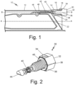
Fig. 1 is a cross-sectional view of a gas turbine engine combustor including a threaded fuel injector. -
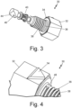
Fig. 2 is an isometric view of the threaded fuel injector for the gas turbine engine combustor ofFig. 1 . -
Fig. 3 is another isometric view of the threaded fuel injector for the gas turbine engine combustor ofFig. 1 . -
Fig. 4 is a close-up view of the threaded fuel injectors ofFig. 2 and3 . - For some applications, such as gas turbine engine applications, it is desirable to control the angular orientation of a threaded component with regard to a larger structure into which the threaded component is installed. Using conventional manufacturing methods, it may not be possible to produce a threaded component that will reliably achieve the desired angular orientation because the required assembly torque or preload is independent of the final position of the angular feature and the required assembly torque or preload can be achieved without achieving the desired angular orientation. Using additive manufacturing (AM) techniques, it is possible control the starting location of the threads on the threaded, male component and the corresponding female hole that is configured to receive the threaded, male component. Controlling the starting location of the threads permits the threaded component to be manufactured so that both torque/preload and final angular location of a feature can be achieved reliably. For example, if the thread starting point and number of turns required to achieve the desired torque/preload are known, the orientation of the angular feature after the threaded component is tightening can be predicted and used as a design criterion for the threaded component.
- AM techniques, including powder bed fusion (PBF) additive manufacturing, can be used to make a wide variety of near net shape parts, including the threaded component and larger structure discussed above. Examples of PBF techniques include PBF-laser (PBF-L) and PBF-electron beam (PBF-EM) processes. For purposes of this disclosure, the larger structure will be described in the context of a unitary, monolithic gas turbine
engine combustor assembly 10 as depicted inFig. 1 . The threaded components will be described in the context of a gas turbineengine fuel injector 30 as depicted inFigs. 1-4 . A person of ordinary skill will understand that the threaded component and larger structure may be any paring of component and structure that would benefit from the designs and techniques described in this disclosure. - As known, the gas turbine
engine combustor assembly 10 receives compressed air from a compressor section (not shown), mixes the air with fuel from afuel injector 30 to create a combustible fuel/air mixture, and burns the fuel/air mixture to generate hot, high velocity combustor exhaust gases that are directed to a turbine section (not shown). The gas turbineengine combustor assembly 10 includes a unitary,monolithic combustor body 12 with aboss 14 havingboss threads 16 for receiving thefuel injector 30 and a visualboss clocking indicator 18. Thecombustor body 12 also includesfuel feed channel 20 anddilution air channel 22. As mentioned above, thecombustor body 12, theboss 14,boss threads 16, visualboss clocking indictor 18,fuel feed channel 20, and dilution air channel 22-plus additional features outside the scope of this disclosure-is formed by AM techniques as a unitary, monolithic structure. Thecombustor 10 is generally arranged along primary combustor axis A as shown inFig. 1 . Thefuel injector 30 is generally arranged along fuel injector axis B, which is parallel to but offset from the primary combustor axis A. Aligning thefuel injector 30 along fuel injector axis B, parallel to but offset from the primary combustor axis A, makes thecombustor assembly 10, which include thecombustor body 12 andfuel injector 30 more compact than current designs, which allows thecombustor assembly 10 to fit into a more compact envelope in the vehicle for which it is intended. -
Figs. 2 and3 , which will be discussed together show thefuel injector 30 in more detail. Thefuel injector 30 is in the form of a bolt with abolt head 32. Thefuel injector 30 includes a visual fuelinjector clocking indicator 34, threadedbody 36 that includesfuel injector threads 38,fuel intakes 40, fuel injector channel 42 (not shown inFig. 2 , seeFig. 1 ), and anangled face 44 that includes a fuel orifice 46 (better seen inFigs. 1 and3 ). Thefuel intakes 40 are positioned such that when thefuel injector 30 is fully threaded into theboss 14, thefuel intakes 40 align with a fuel feed channel 20 (seeFig. 1 ) formed as an integral part of the unitary,monolithic combustor body 12. In the context of this disclosure, "fully threaded" means that thefuel injector 30 is threaded into theboss threads 16 of theboss 14 to achieve both the desired torque/preload and the desired final angular location of thatfuel orifice 46. When thefuel injector 30 is in operation, fuel enters thefuel intakes 40 from thefuel feed channel 20 and flows through thefuel injector channel 42 to thefuel orifice 46, where the fuel exits thefuel injector 30 and mixes with air flowing through the air dilution channel 22 (seeFig. 1 ). Thefuel orifice 46 is formed in theangled face 44 to direct fuel exiting thefuel injector 30 to enter the air flowing through theair dilution channel 22 in a desired orientation to provide a desired degree of mixing between the fuel and the air. The specific size and dimensions of thefuel orifice 46 and the specific angle of theangled face 44 are selected to provide the desired degree of mixing between the fuel and the air when thefuel injector 30 is fully threaded into theboss 14. -
Fig. 4 shows an enlarged view of a portion of thefuel injector 30, highlighting the visual fuelinjector clocking indicator 34 and the portion of thefuel injector body 36 that includes the final portion of thefuel injector threads 38 and afastener arresting face 48. Thefastener arresting face 48 is configured to cooperate with a boss thread arresting face (not shown) that forms a part of theboss threads 16 of theboss 14 to stop rotation of thefuel injector 30 while it is threaded into theboss 14 when thefuel injector 30 is fully threaded into the boss 14 (i.e., thefuel injector 30 achieves both the desired torque/preload and the desired final angular location of that fuel orifice 46). At this point, the visual fuelinjector clocking indicator 34 will align with a corresponding visual boss clocking indicator 18 (seeFig. 1 ) on the unitary,monolithic combustor body 12. - As discussed above, it is possible to control the starting location of the
fuel injector threads 38 on thefuel injector 30 and theboss threads 16 of theboss 14 using AM techniques. Controlling the starting location of thefuel injector threads 38 and theboss threads 16 permits thefuel injector 30 to be manufactured so that both torque/preload and final angular location of thefuel orifice 46 can be achieved reliably. Knowing the number of turns required to achieve the desired torque/preload on thefuel injector 30, the orientation of thefuel orifice 46 after thefuel injector 30 is tightened (i.e., "fully threaded") can be predicted and used as a design criterion to determine the starting point for thefuel injector threads 38 and theboss threads 16. - Any AM technique can be used for forming the unitary,
monolithic combustor body 12, including thefuel feed channel 20 anddilution air channel 22, and thefuel injector 30, including thefuel intakes 40 andfuel orifice 46. If desired for a particular application, thefuel intakes 40 andfuel orifice 46 can be formed using mechanical machining processes in post-processing steps. The unitary,monolithic combustor body 12 and thefuel injector 30 can be made with any materials deem suitable for the particular application. For example, nickel-based alloys, such as INCO 625, can be used for the disclosed unitary,monolithic combustor body 12 and thefuel injector 30 to address the high temperatures encountered in these structures. - The AM technique can be PBF-L or PBF-EB or any other suitable AM technique. Although forming precise threads using AM techniques can be challenging, threads made using AM techniques can be "cleaned up" using a post-processing thread chasing step. For example, the
fuel injector threads 38 on thefuel injector 30, including thefastener arresting face 48, and theboss threads 16 of theboss 14, including the boss thread arresting face, can be made with a PBF-L process. After the PBF-L process for each of thefuel injector 30 and the unitary,monolithic combustor body 12 is finished, thefuel injector threads 38 and theboss threads 16 are chased using techniques known in the art to establish finished threads. Once manufactured, thecombustor assembly 10 can be completed by threading thefuel injector 30 into theboss 14 as described above. - As discussed above, the
combustor assembly 10 of this disclosure fits into a more compact envelope in the vehicle for which it is intended. The alignment features on the fuel injector 30 (the visual fuelinjector clocking indicator 34 and the fastener arresting face 48) and the boss 14 (visualboss clocking indictor 18 and the boss thread arresting face) provide physical and visual mistake proofing to ensure desired orientation of thefuel orifice 46 in theair dilution channel 22. Combining AM manufacturing techniques with selected post-processing steps, i.e., chasing of thefuel injector threads 38 and theboss threads 16 and, if desired, formation of thefuel orifice 46 in theangled face 44 provide cost effective, precision manufacturing to thecombustor assembly 10. - The following are non-exclusive descriptions of possible embodiments of the present invention.
- A fuel injector bolt comprises a bolt head having a visual fuel injector clocking indicator, a threaded body that includes fuel injector threads, one or more fuel intakes, a fuel injector channel, and an angled face that includes a fuel orifice. The fuel injector threads include a fastener arresting face.
- The fuel injector bolt of the preceding paragraph can optionally include, additionally and/or alternatively, any one or more of the following features, configurations and/or additional elements:
- The fuel injector bolt of the preceding paragraph, wherein the visual fuel injector clocking indicator is configured to align with a visual boss clocking indicator when the fuel injector bolt is fully threaded into a unitary, monolithic combustor body boss.
- The fuel injector bolt of any of the preceding paragraphs, wherein the fuel injector threads are configured to engage with boss threads and the fastener arresting face is configured to engage with a boss arrestor face when the fuel injector bolt is fully threaded into a unitary, monolithic combustor body boss, wherein the boss threads are positioned in a unitary, monolithic combustor body boss and the boss arrestor face is formed in the boss threads.
- The fuel injector bolt of any of the preceding paragraphs, wherein the one or more fuel intakes are configured to align with a fuel injector channel formed in a unitary, monolithic combustor body.
- The fuel injector bolt of any of the preceding paragraphs, wherein the fuel orifice is configured to deliver fuel into a dilution air channel formed in a unitary, monolithic combustor body.
- The fuel injector bolt of any of the preceding paragraphs, wherein the fuel injector bolt is formed from a nickel-based alloy using additive manufacturing techniques.
- A gas turbine engine combustor comprising a unitary, monolithic combustor body and a unitary, monolithic combustor body boss formed in the unitary, monolithic combustor body. The unitary, monolithic combustor body includes boss threads and a visual boss clocking indicator. The unitary, monolithic combustor body boss is configured to receive, with the boss threads, a fuel injector bolt. The fuel injector bolt comprises a bolt head having a visual fuel injector clocking indicator, a threaded body that includes fuel injector threads, wherein the fuel injector threads include a fastener arresting face, one or more fuel intakes, a fuel injector channel, and an angled face that includes a fuel orifice.
- The gas turbine engine combustor of the preceding paragraph, wherein the visual fuel injector clocking indicator is configured to align with a visual boss clocking indicator when the fuel injector bolt is fully threaded into a unitary, monolithic combustor body boss.
- The gas turbine engine combustor of any of the preceding paragraphs, wherein the fuel injector threads are configured to engage with boss threads and the fastener arresting face is configured to engage with a boss arrestor face when the fuel injector bolt is fully threaded into a unitary, monolithic combustor body boss, wherein the boss threads are positioned in a unitary, monolithic combustor body boss and the boss arrestor face is formed in the boss threads.
- The gas turbine engine combustor of any of the preceding paragraphs, wherein the one or more fuel intakes are configured to align with a fuel injector channel formed in a unitary, monolithic combustor body.
- The gas turbine engine combustor of any of the preceding paragraphs, wherein the fuel orifice is configured to deliver fuel into a dilution air channel formed in a unitary, monolithic combustor body.
- The gas turbine engine combustor of any of the preceding paragraphs, wherein the fuel injector bolt is formed from a nickel-based alloy using additive manufacturing techniques.
- The gas turbine engine combustor of any of the preceding paragraphs, wherein the unitary, monolithic combustor body is positioned along a primary combustor axis and the fuel injector bolt is positioned along a fuel injector axis, wherein the fuel injector axis is parallel with but offset from the primary combustor axis.
- A method of making a gas turbine engine combustor comprises forming, using additive manufacturing (AM) techniques, a unitary, monolithic combustor body. The unitary, monolithic combustor body has a unitary, monolithic combustor body boss formed in the unitary, monolithic combustor body, wherein the unitary, monolithic combustor body includes boss threads and a visual boss clocking indicator, wherein the unitary, monolithic combustor body boss is configured to receive, with the boss threads, a fuel injector bolt. The boss threads are chased to finish the boss threads. Forming, using AM techniques, the fuel injector bolt having a bolt head having a visual fuel injector clocking indicator, a threaded body that includes fuel injector threads, wherein the fuel injector threads include a fastener arresting face, one or more fuel intakes, a fuel injector channel, and an angled face that includes a fuel orifice. The fuel injector threads are chased to finish the fuel injector threads. The fuel injector threads of the fuel injector bolt are aligned with the boss threads of the unitary, monolithic combustor body boss and the fuel injector bolt is threaded into the unitary, monolithic combustor body boss until the fastener arresting face on the fuel injector threads engages with a boss arresting face on the boss threads, thereby stopping rotation of the fuel injector bolt in the unitary, monolithic combustor body boss. When the fastener arresting face on the fuel injector threads engages with the boss arresting face on the boss threads the visual fuel injector clocking indicator on the bolt head aligns with the visual boss clocking indicator on the unitary, monolithic combustor body boss.
- The method of the preceding paragraph, wherein the one or more fuel intakes are configured to align with a fuel injector channel formed in a unitary, monolithic combustor body.
- The method of any of the preceding paragraphs, wherein the fuel orifice is configured to deliver fuel into a dilution air channel formed in a unitary, monolithic combustor body.
- The method of any of the preceding paragraphs, wherein the fuel injector bolt is formed from a nickel-based alloy using additive manufacturing techniques.
- The method of any of the preceding paragraphs, wherein the unitary, monolithic combustor body is positioned along a primary combustor axis and the fuel injector bolt is positioned along a fuel injector axis, wherein the fuel injector axis is parallel with but offset from the primary combustor axis.
- While the invention has been described with reference to an exemplary embodiment(s), it will be understood by those skilled in the art that various changes may be made and equivalents may be substituted for elements thereof without departing from the scope of the invention. In addition, many modifications may be made to adapt a particular situation or material to the teachings of the invention without departing from the essential scope thereof. Therefore, it is intended that the invention not be limited to the particular embodiment(s) disclosed, but that the invention will include all embodiments falling within the scope of the appended claims.
Claims (13)
- A fuel injector bolt comprising:a bolt head (32) having a visual fuel injector clocking indicator (34);a threaded body (36) that includes fuel injector threads (38), wherein the fuel injector threads (38) include a fastener arresting face (48);one or more fuel intakes (40);a fuel injector channel (42); andan angled face (44) that includes a fuel orifice (46).
- The fuel injector bolt of claim 1, wherein the visual fuel injector clocking indicator (34) is configured to align with a visual boss clocking indicator (18) when the fuel injector bolt (30) is fully threaded into a unitary, monolithic combustor body boss (14).
- The fuel injector bolt of claim 1 or 2, wherein the fuel injector threads (38) are configured to engage with boss threads (16) and the fastener arresting face (48) is configured to engage with a boss arrestor face when the fuel injector bolt (30) is fully threaded into a or the unitary, monolithic combustor body boss (14), wherein the boss threads (16) are positioned in the unitary, monolithic combustor body boss (14) and the boss arrestor face is formed in the boss threads (16).
- The fuel injector bolt of any preceding claim, wherein the one or more fuel intakes (40) are configured to align with a fuel injector channel (20) formed in a or the unitary, monolithic combustor body (12).
- The fuel injector bolt of any preceding claim, wherein the fuel orifice (46) is configured to deliver fuel into a dilution air channel (22) formed in a or the unitary, monolithic combustor body (12).
- The fuel injector bolt of any preceding claim, wherein the fuel injector bolt (30) is formed from a nickel-based alloy using additive manufacturing techniques.
- A gas turbine engine combustor, comprising:a unitary, monolithic combustor body (12);a unitary, monolithic combustor body boss (14) formed in the unitary, monolithic combustor body (12), wherein the unitary, monolithic combustor body (12) includes boss threads (16) and a visual boss clocking indicator (18), wherein the unitary, monolithic combustor body boss (14) is configured to receive, with the boss threads (16), the fuel injector bolt (30) of any preceding claim.
- The gas turbine engine combustor of claim 7, wherein the unitary, monolithic combustor body (12) is positioned along a primary combustor axis (A) and the fuel injector bolt (30) is positioned along a fuel injector axis (B), wherein the fuel injector axis (B) is parallel with but offset from the primary combustor axis (A).
- A method of making a gas turbine engine combustor, comprising:forming, using additive manufacturing (AM) techniques, a unitary, monolithic combustor body (12) having a unitary, monolithic combustor body boss (14) formed in the unitary, monolithic combustor body (12), wherein the unitary, monolithic combustor body (12) includes boss threads (16) and a visual boss clocking indicator (18), wherein the unitary, monolithic combustor body boss (14) is configured to receive, with the boss threads (16), a fuel injector bolt (30);chasing the boss threads (16) to finish the boss threads (16);forming, using AM techniques, the fuel injector bolt (30) having:a bolt head (32) having a visual fuel injector clocking indicator (34);a threaded body (36) that includes fuel injector threads (38), wherein the fuel injector threads (38) include a fastener arresting face (48);one or more fuel intakes (40);a fuel injector channel (42); andan angled face (44) that includes a fuel orifice (46);chasing the fuel injector threads (38) to finish the fuel injector threads (38);aligning the fuel injector threads (38) of the fuel injector bolt (30) with the boss threads (16) of the unitary, monolithic combustor body boss (14); andthreading the fuel injector bolt (30) into the unitary, monolithic combustor body boss (14) until the fastener arresting face (48) on the fuel injector threads (38) engages with a boss arresting face on the boss threads (16), thereby stopping rotation of the fuel injector bolt (30) in the unitary, monolithic combustor body boss (14), wherein when the fastener arresting face (48) on the fuel injector threads (38) engages with the boss arresting face on the boss threads (16) the visual fuel injector clocking indicator (34) on the bolt head (32) aligns with the visual boss clocking indicator (18) on the unitary, monolithic combustor body boss (14).
- The method of claim 9, wherein the one or more fuel intakes (40) are configured to align with a fuel injector channel (20) formed in the unitary, monolithic combustor body (12).
- The method of claim 9 or 10, wherein the fuel orifice (46) is configured to deliver fuel into a dilution air channel (22) formed in the unitary, monolithic combustor body (12).
- The method of any of claims 9 to 11, wherein the fuel injector bolt (30) is formed from a nickel-based alloy using additive manufacturing techniques.
- The method of any of claims 9 to 12, wherein the unitary, monolithic combustor body (12) is positioned along a primary combustor axis (A) and the fuel injector bolt (30) is positioned along a fuel injector axis (B), wherein the fuel injector axis (B) is parallel with but offset from the primary combustor axis (A).
Applications Claiming Priority (1)
| Application Number | Priority Date | Filing Date | Title |
|---|---|---|---|
| US18/496,615 US20250137642A1 (en) | 2023-10-27 | 2023-10-27 | Additive clocked fuel injector bolt |
Publications (2)
| Publication Number | Publication Date |
|---|---|
| EP4545855A2 true EP4545855A2 (en) | 2025-04-30 |
| EP4545855A3 EP4545855A3 (en) | 2025-05-14 |
Family
ID=93258967
Family Applications (1)
| Application Number | Title | Priority Date | Filing Date |
|---|---|---|---|
| EP24208409.3A Pending EP4545855A3 (en) | 2023-10-27 | 2024-10-23 | Additively manufactured clocked fuel injector bolt for gas turbine engine combustor |
Country Status (2)
| Country | Link |
|---|---|
| US (1) | US20250137642A1 (en) |
| EP (1) | EP4545855A3 (en) |
Family Cites Families (11)
| Publication number | Priority date | Publication date | Assignee | Title |
|---|---|---|---|---|
| US1986061A (en) * | 1932-11-05 | 1935-01-01 | Clark Metal Products Inc | Lock thread for screw caps and the like |
| US3192711A (en) * | 1962-11-29 | 1965-07-06 | Bob C Miller | Nozzle position and afterburner lighting indicator |
| US5033263A (en) * | 1989-03-17 | 1991-07-23 | Sundstrand Corporation | Compact gas turbine engine |
| US5277022A (en) * | 1990-06-22 | 1994-01-11 | Sundstrand Corporation | Air blast fuel injecton system |
| WO2015112385A1 (en) * | 2014-01-24 | 2015-07-30 | United Technologies Corporation | Thermally compliant additively manufactured fuel injector |
| US10518321B2 (en) * | 2016-12-22 | 2019-12-31 | Siemens Aktiengesellschaft | Casting method and manifold cast with conduits effective for removing a core from the cast without forming extraneous holes in the body of the manifold |
| US11021986B2 (en) * | 2018-03-20 | 2021-06-01 | Raytheon Technologies Corporation | Seal assembly for gas turbine engine |
| US11060460B1 (en) * | 2019-04-01 | 2021-07-13 | Marine Turbine Technologies, LLC | Fuel distribution system for gas turbine engine |
| US11846421B2 (en) * | 2020-02-14 | 2023-12-19 | Rtx Corporation | Integrated fuel swirlers |
| US11543127B2 (en) * | 2020-02-14 | 2023-01-03 | Raytheon Technologies Corporation | Gas turbine engine dilution chute geometry |
| US12066188B2 (en) * | 2021-03-26 | 2024-08-20 | Rtx Corporation | Modular injector bolt for an engine |
-
2023
- 2023-10-27 US US18/496,615 patent/US20250137642A1/en active Pending
-
2024
- 2024-10-23 EP EP24208409.3A patent/EP4545855A3/en active Pending
Also Published As
| Publication number | Publication date |
|---|---|
| EP4545855A3 (en) | 2025-05-14 |
| US20250137642A1 (en) | 2025-05-01 |
Similar Documents
| Publication | Publication Date | Title |
|---|---|---|
| US7805944B2 (en) | Combustion chamber air inlet | |
| US6553767B2 (en) | Gas turbine combustor liner with asymmetric dilution holes machined from a single piece form | |
| EP2873921B1 (en) | Combustion chamber heat shield element of a gas turbine | |
| US6581386B2 (en) | Threaded combustor baffle | |
| US8511088B2 (en) | Gas turbine fuel injector mounting system | |
| US9534783B2 (en) | Insert adjacent to a heat shield element for a gas turbine engine combustor | |
| US10393145B2 (en) | Asymmetric alignment system for a variable stator vane | |
| US6502400B1 (en) | Combustor dome assembly and method of assembling the same | |
| US7967562B2 (en) | Ceramic matrix composite capped bolt attachment | |
| US20080010991A1 (en) | Method and apparatus to facilitate reducing NOx emissions in turbine engines | |
| US20110123323A1 (en) | Attaching ceramic matrix composite to high temperature gas turbine structure | |
| EP2886962A1 (en) | A combustion chamber | |
| AU2006200260A1 (en) | Fuel injector bearing plate assembly and swirler assembly | |
| US10077714B2 (en) | Repairable fuel injector | |
| EP2189720A1 (en) | Burner assembly | |
| CN110500611A (en) | Component for turbine engine combustion chamber | |
| EP3098516A1 (en) | Injection boss for a unibody combustor | |
| US20250137642A1 (en) | Additive clocked fuel injector bolt | |
| EP3533974B1 (en) | Variable vane arm retention feature | |
| US10132176B2 (en) | Split airfoil cluster and method therefor | |
| US6844520B2 (en) | Methods for fabricating gas turbine engine combustors | |
| US20210254831A1 (en) | Gas turbine engine dilution chute geometry | |
| US10808612B2 (en) | Retaining tab for diffuser seal ring | |
| US20150082806A1 (en) | Micro-Mixer Fuel Plenum and Methods for Fuel Tube Installation | |
| EP3184900B1 (en) | Fuel injection device |
Legal Events
| Date | Code | Title | Description |
|---|---|---|---|
| PUAI | Public reference made under article 153(3) epc to a published international application that has entered the european phase |
Free format text: ORIGINAL CODE: 0009012 |
|
| STAA | Information on the status of an ep patent application or granted ep patent |
Free format text: STATUS: THE APPLICATION HAS BEEN PUBLISHED |
|
| PUAL | Search report despatched |
Free format text: ORIGINAL CODE: 0009013 |
|
| AK | Designated contracting states |
Kind code of ref document: A2 Designated state(s): AL AT BE BG CH CY CZ DE DK EE ES FI FR GB GR HR HU IE IS IT LI LT LU LV MC ME MK MT NL NO PL PT RO RS SE SI SK SM TR |
|
| AK | Designated contracting states |
Kind code of ref document: A3 Designated state(s): AL AT BE BG CH CY CZ DE DK EE ES FI FR GB GR HR HU IE IS IT LI LT LU LV MC ME MK MT NL NO PL PT RO RS SE SI SK SM TR |
|
| RIC1 | Information provided on ipc code assigned before grant |
Ipc: F23R 3/54 20060101ALI20250407BHEP Ipc: F23R 3/28 20060101AFI20250407BHEP |
|
| STAA | Information on the status of an ep patent application or granted ep patent |
Free format text: STATUS: REQUEST FOR EXAMINATION WAS MADE |
|
| 17P | Request for examination filed |
Effective date: 20251112 |
|
| GRAP | Despatch of communication of intention to grant a patent |
Free format text: ORIGINAL CODE: EPIDOSNIGR1 |
|
| STAA | Information on the status of an ep patent application or granted ep patent |
Free format text: STATUS: GRANT OF PATENT IS INTENDED |
|
| INTG | Intention to grant announced |
Effective date: 20260305 |