EP2189720A1 - Burner assembly - Google Patents
Burner assembly Download PDFInfo
- Publication number
- EP2189720A1 EP2189720A1 EP08020335A EP08020335A EP2189720A1 EP 2189720 A1 EP2189720 A1 EP 2189720A1 EP 08020335 A EP08020335 A EP 08020335A EP 08020335 A EP08020335 A EP 08020335A EP 2189720 A1 EP2189720 A1 EP 2189720A1
- Authority
- EP
- European Patent Office
- Prior art keywords
- carrier
- nozzle
- fuel
- nozzle lance
- arrangement according
- Prior art date
- Legal status (The legal status is an assumption and is not a legal conclusion. Google has not performed a legal analysis and makes no representation as to the accuracy of the status listed.)
- Ceased
Links
Images
Classifications
-
- F—MECHANICAL ENGINEERING; LIGHTING; HEATING; WEAPONS; BLASTING
- F23—COMBUSTION APPARATUS; COMBUSTION PROCESSES
- F23R—GENERATING COMBUSTION PRODUCTS OF HIGH PRESSURE OR HIGH VELOCITY, e.g. GAS-TURBINE COMBUSTION CHAMBERS
- F23R3/00—Continuous combustion chambers using liquid or gaseous fuel
- F23R3/28—Continuous combustion chambers using liquid or gaseous fuel characterised by the fuel supply
- F23R3/283—Attaching or cooling of fuel injecting means including supports for fuel injectors, stems, or lances
-
- F—MECHANICAL ENGINEERING; LIGHTING; HEATING; WEAPONS; BLASTING
- F23—COMBUSTION APPARATUS; COMBUSTION PROCESSES
- F23D—BURNERS
- F23D23/00—Assemblies of two or more burners
-
- F—MECHANICAL ENGINEERING; LIGHTING; HEATING; WEAPONS; BLASTING
- F23—COMBUSTION APPARATUS; COMBUSTION PROCESSES
- F23R—GENERATING COMBUSTION PRODUCTS OF HIGH PRESSURE OR HIGH VELOCITY, e.g. GAS-TURBINE COMBUSTION CHAMBERS
- F23R3/00—Continuous combustion chambers using liquid or gaseous fuel
- F23R3/28—Continuous combustion chambers using liquid or gaseous fuel characterised by the fuel supply
- F23R3/36—Supply of different fuels
-
- F—MECHANICAL ENGINEERING; LIGHTING; HEATING; WEAPONS; BLASTING
- F23—COMBUSTION APPARATUS; COMBUSTION PROCESSES
- F23C—METHODS OR APPARATUS FOR COMBUSTION USING FLUID FUEL OR SOLID FUEL SUSPENDED IN A CARRIER GAS OR AIR
- F23C2900/00—Special features of, or arrangements for combustion apparatus using fluid fuels or solid fuels suspended in air; Combustion processes therefor
- F23C2900/07021—Details of lances
-
- F—MECHANICAL ENGINEERING; LIGHTING; HEATING; WEAPONS; BLASTING
- F23—COMBUSTION APPARATUS; COMBUSTION PROCESSES
- F23R—GENERATING COMBUSTION PRODUCTS OF HIGH PRESSURE OR HIGH VELOCITY, e.g. GAS-TURBINE COMBUSTION CHAMBERS
- F23R2900/00—Special features of, or arrangements for continuous combustion chambers; Combustion processes therefor
- F23R2900/00018—Manufacturing combustion chamber liners or subparts
Definitions
- the present invention relates to a burner assembly and more particularly to a burner assembly for gas turbines.
- a gas turbine comprises as essential components a compressor, a turbine with moving blades and at least one combustion chamber.
- the blades of the turbine are arranged as blade rings on a shaft extending mostly through the entire gas turbine, which is coupled to a consumer, such as a generator for power generation.
- the shaft provided with the blades is also called turbine runner or rotor. Between the blade rings are vanes, which serve as nozzles for guiding the working fluid through the turbine.
- the combustion chamber is supplied with compressed air from the compressor.
- the compressed air is mixed with a fuel, such as oil or gas, and the mixture burned in the combustion chamber.
- the hot combustion exhaust gases are finally supplied as a working medium via a combustion chamber outlet of the turbine, where they transmit momentum to the blades under relaxation and cooling and thus do work.
- the vanes serve to optimize the momentum transfer.
- a typical burner assembly for gas turbines as shown in US 6,082,111 is described and how it is used in particular in so-called tube combustion chambers, usually has an annular support with uniformly distributed around the circumference of the ring nozzle lances.
- fuel nozzle openings are arranged, with which fuel can be injected into an air supply channel.
- the fuel nozzles represent a main stage of the burner, which is used to generate a premix flame, ie a flame, in which the air and the fuel mix before igniting become, serve.
- premix burners are operated with lean air-fuel mixtures, ie with mixtures which contain relatively little fuel.
- pilot burner which is designed as a diffusion burner, i. it produces a flame in which the fuel is injected directly into the flame without first being mixed with air.
- the pilot burner in addition to starting the gas turbine, also serves to stabilize the premix flame which, to minimize emissions, is often operated in a range of air to fuel mixing ratio which could lead to flame instabilities without assisting the pilot flame.
- a burner assembly such as the burner assembly described, typically includes a number of nozzle lances machined from a metal block and welded to the carrier.
- Each nozzle lance has a gas supply passage extending from its wearer-side end to the nozzle openings. Through the gas supply passage also extends a liquid fuel supply piping leading to fuel nozzles for injecting the liquid fuel.
- the carrier has corresponding bushings for the fuel piping and gas passages.
- the gas passages are typically milled by machine into a cylindrical carrier blank and then covered with welded-on elements.
- the bushings for the pipelines are machined into the carrier blank.
- the carrier blank and thus the subsequent carrier must have a certain minimum thickness. This increases the weight of the burner assembly and the material costs. In addition, machine incorporation is laborious.
- a burner arrangement comprises a carrier, which in particular can be designed as an annular carrier, and a number of nozzle lances each containing at least one fuel nozzle opening.
- a fuel supply system extends to the fuel nozzle openings.
- At least two nozzle lance elements are attached to the carrier, each of which comprises a carrier-side section and at least two nozzle lances extending from the carrier-side section and formed integrally therewith.
- the inventive design of the burner assembly makes it possible to reduce the number of fuel passages and feedthroughs in the carrier compared to the prior art, since only one passage or passage is required by the carrier for each nozzle lance element.
- the branching of the passages and passages then takes place only in the carrier-side section of the nozzle lance element.
- the material thickness of the carrier can be reduced, whereby weight and cost can be saved.
- the number of connections is reduced at the side facing away from the nozzle lances of the burner, which reduces the effort when connecting the burner assembly to the fuel system of the gas turbine.
- the requirements for the installation space of the burner assembly in the region of the side facing away from the nozzle lances side of the carrier in comparison to State of the art less strict. Overall, the machining of the carrier is simplified.
- the fuel supply system may include gaseous fuel fuel passages in the nozzle lance elements extending from the carrier to the nozzle orifice of the nozzle lance through the nozzle lance elements.
- the sections of the fuel passages extending through the individual nozzle lances open into a single common fuel passage section in the carrier-side section of the respective nozzle lance element.
- the fuel supply system may include fuel tube outputs in the nozzle lance elements extending from the carrier to the respective nozzle orifice of the nozzle lances through the nozzle lance elements.
- the extending through the individual nozzle lances portions of the fuel pipes then open in the carrier-side portion of the respective nozzle lance element in a single common pipe section, which can then be passed through the carrier.
- the fuel piping may be disposed inside the fuel passages.
- This configuration makes it possible in particular to provide only a single fuel passage for gaseous fuel per nozzle lance element in the carrier through which the fuel pipeline is also guided.
- the carrier for each nozzle lance element only has to be provided with a single bore, which significantly reduces the cost and expense when editing the carrier.
- the blank may be formed for the carrier as a relatively flat annular disc, which reduces material and cost in producing the carrier.
- the carrier-side sections of the nozzle lance elements may have a carrier-side opening provided with a cover, wherein the opening is large enough to possibly pass the fuel piping through the opening can. It is then possible to produce the branched fuel pipelines outside the nozzle lance elements and then introduce them through the large opening in the nozzle lance elements. Producing the branched fuel pipelines outside the nozzle lance elements is simpler than connecting the individual sections of the fuel pipelines when they are already inside the nozzle lance elements.
- the cover can be soldered to the respective nozzle lance element after introduction of the fuel piping. Brazing methods are particularly suitable for soldering, ie soldering methods in which the liquidus temperature of the solder is above 450.degree. The soldering offers the advantage over welding that there is no deformation of the nozzle lance element or of the carrier plate compared with welding, so that post-processing after the connection is not necessary. The same applies to the connection of the individual pipe sections in the fuel supply system.
- the cover has a pipe piece projecting in the direction of the support, the end remote from the cover having a first fastening element.
- the tube piece is guided through a through hole in the carrier, and the corresponding nozzle lance element is fixed to the carrier by means of a second fastening element cooperating with the first fastening element.
- This embodiment makes it possible to design the fixation on the carrier releasably, for example, in which the first fastening element is an external thread of the pipe section and the second fastening element is a nut.
- the inner volume of the pipe section can also be used simultaneously as a fuel passage, through which the fuel pipe can be guided.
- a single bore present in the carrier can thus be used to fix a nozzle lance element on the carrier and a gaseous and a liquid fuel to the individual nozzle lances of the nozzle lance element supply.
- the removal and replacement of a nozzle lance element can then be done in a simple manner by loosening the screw and by separating the fuel pipe.
- the carrier-side portions of the nozzle lance elements carrier side each have a contact surface, with which they on a corresponding contact surface abut the wearer.
- At least one seal is preferably present between a nozzle lance element and the carrier.
- a seal may in particular be designed as a c-ring seal. These are particularly well suited as seals due to their springback properties. In principle, however, other resilient seals such as o-ring seals are possible. Due to the elasticity of the seal, excessive restrictions on relative movements, which could occur, for example, due to the operational heating of the components, can be avoided.
- the seal may, for example, be arranged between the carrier and the pipe section in the region of the through hole.
- the nozzle lance elements of the burner assembly according to the invention may be formed instead of machined parts, in particular as castings. Compared to machined parts, castings are characterized by their less laborious production. In addition, castings are mass-produced and therefore inexpensive to manufacture.
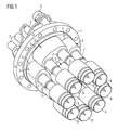
- Fig. 1 a burner assembly for a gas turbine shown in perspective.
- the burner assembly comprises an annular support with a central opening and - in the present embodiment - four arranged on the support 1 around the central opening around and fixed nozzle lance elements 3.
- Each nozzle lance element 3 has a carrier-side section 5, with which it is attached to the carrier 1 and two From the carrier-side portion outgoing nozzle lances 7, at which the carrier-side section 5 remote ends swirl generator (Swirler) 9 are attached.
- the fuel supply system includes gas supply passages 11 (in FIG Fig. 1 not visible) for gaseous fuels, as well as pipelines for liquid fuels, such as oil, both of which extend through the support plate 1 and the nozzle lance elements 3 to gas nozzles 17 and nozzles 15 for liquid fuels in the nozzle lances 7 ( Fig. 2 ).
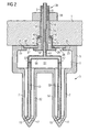
- Fig. 2 shows a sectional view through the support plate 1 and a nozzle lance element 3.
- the carrier plate 1 is essentially a machined solid workpiece formed in which for the passage of fuel supply lines to the nozzle lance elements 3 and for attaching the nozzle lance elements 3 to the support plate 1 through holes in the form of holes 19 are present.
- the holes 19 have on the side of the support plate 1, on which the nozzle lance elements 3 are arranged, a section 21 with an enlarged cross section.
- the nozzle lance elements 3 with the nozzle lances 7 are formed as one-piece, hollow-cast components.
- the carrier-plate-side section 5 of the nozzle lance elements 3 has a planar contact surface 23, with which it bears against a corresponding planar contact surface 25 of the carrier plate 1.
- In the center of the contact surface 23 is an opening 26 in the carrier plate-side section 5, through which the pipes 13 for the liquid fuel can be passed.
- This opening 26 is closed by a cover plate 27, which can be connected in particular to the edge of the opening 26 by a brazing.
- a tube 29 is inserted therethrough, which in the axial direction of the cover plate 27, starting from a section 31 having a wide outer diameter and a portion 33 having a smaller outer diameter.
- the tube 29 also has at its located in the interior of the carrier-side section 5 of the nozzle lance element 7 end a flange 37, with which it bears against the inside of the cover plate 27.
- the tube 29 may be bolted to the support plate 27 or advantageously be connected by a braze with the cover plate 27. The brazing is particularly advantageous in view of the gas tightness of the compound.
- the tube 29 is inserted through the bore 19 in the support plate 1, wherein it protrudes with the free end of the tube 34 from the support plate 1.
- the pipe end 34 which can also serve as a connection for fuel supply lines, is provided with an external thread 35, so that a nut 39 is screwed can be to fix the nozzle lance element 3 to the support plate 1.
- the contact surface 23 serves to stabilize the position of the nozzle lance element 3 relative to the carrier plate 1.
- the axial length of the large-diameter pipe portion 31 corresponds to the axial length of the enlarged-section bore portion 21.
- annular surface 41 is formed, which has a groove 43 for receiving a seal 45.
- the seal is formed in the present embodiment as a c-ring seal 45 which is inserted with its open side in the groove 43.
- other seals could also be used, for example o-ring seals.
- C-ring seals are particularly suitable because of their very good spring properties.
- the seal 45 serves to prevent leakage of compressor air.
- a cavity 51 in the carrier plate side portion 5 of the hollow-die-cast nozzle lance element 3 together with the free volume 52 of the nozzle lance 7 serves as a gas passage to the gas nozzles 17
- the pipeline 13 has two branch lines 53 which extend through the respective nozzle lance 7 as far as the nozzle openings for liquid fuels 15.
- the running through the nozzle lances 7 pipe sections 53 are connected in the present embodiment via a brazed joint 57 with a T-shaped connecting portion 55 of the pipe 13, but also a one-piece design of the pipe 13 with the pipe sections 53 is basically possible.
- the burner assembly according to the invention allows a particularly simple embodiment of the carrier 1, namely as an annular support plate, in which only through holes for the passage of the tubes 29 must be introduced.
- the tubes 29 are then used both for gas supply and for the supply of liquid fuels by means of pipes 29 guided through the pipes 13.
- the fact that the nozzle lance elements 3 are connected to the support plate 1 only by means of a screw connection (external thread in the section 35 and nut 39) enables easy removal and replacement of the nozzle lance elements 3. If a nozzle lance element 3 is to be replaced, only the screw connection is required to be solved and the pipe 13 to be separated from the outside of the burner assembly located feed lines. A stable fixation of the position of the nozzle lance elements can be achieved by the contact surface 23 on the nozzle lance element 3 in cooperation with the system 25 of the support plate 1.
Landscapes
- Engineering & Computer Science (AREA)
- Chemical & Material Sciences (AREA)
- Combustion & Propulsion (AREA)
- Mechanical Engineering (AREA)
- General Engineering & Computer Science (AREA)
- Gas Burners (AREA)
Abstract
Description
Die vorliegende Erfindung betrifft eine Brenneranordnung und insbesondere eine Brenneranordnung für Gasturbinen.The present invention relates to a burner assembly and more particularly to a burner assembly for gas turbines.
Eine Gasturbine umfasst als wesentliche Bestandteile einen Verdichter, eine Turbine mit Laufschaufeln sowie wenigstens eine Brennkammer. Die Laufschaufeln der Turbine sind als Laufschaufelkränze an einer sich zumeist durch die gesamte Gasturbine erstreckende Welle angeordnet, die mit einem Verbraucher, etwa einem Generator zur Stromerzeugung, gekoppelt ist. Die mit den Laufschaufeln versehene Welle wird auch Turbinenläufer oder Rotor genannt. Zwischen den Laufschaufelkränzen befinden sich Leitschaufelkränze, die als Düsen zum Leiten des Arbeitsmediums durch die Turbine dienen.A gas turbine comprises as essential components a compressor, a turbine with moving blades and at least one combustion chamber. The blades of the turbine are arranged as blade rings on a shaft extending mostly through the entire gas turbine, which is coupled to a consumer, such as a generator for power generation. The shaft provided with the blades is also called turbine runner or rotor. Between the blade rings are vanes, which serve as nozzles for guiding the working fluid through the turbine.
Im Betrieb der Gasturbine wird der Brennkammer verdichtete Luft aus dem Verdichter zugeführt. Die verdichtete Luft wird mit einem Brennstoff, beispielsweise Öl oder Gas, vermischt und das Gemisch in der Brennkammer verbrannt. Die heißen Verbrennungsabgase werden schließlich als Arbeitsmedium über einen Brennkammerausgang der Turbine zugeführt, wo sie unter Entspannung und Abkühlung Impuls auf die Laufschaufeln übertragen und so Arbeit leisten. Die Leitschaufeln dienen dabei zum Optimieren des Impulsübertrags.During operation of the gas turbine, the combustion chamber is supplied with compressed air from the compressor. The compressed air is mixed with a fuel, such as oil or gas, and the mixture burned in the combustion chamber. The hot combustion exhaust gases are finally supplied as a working medium via a combustion chamber outlet of the turbine, where they transmit momentum to the blades under relaxation and cooling and thus do work. The vanes serve to optimize the momentum transfer.
Eine typische Brenneranordnung für Gasturbinen, wie sie in
Durch das Zentrum des ringförmigen Trägers erstreckt sich typischerweise ein Pilotbrenner, der als Diffusionsbrenner ausgebildet ist, d.h. er erzeugt eine Flamme, bei welcher der Brennstoff direkt in die Flamme eingedüst wird, ohne vorher mit Luft vermischt zu werden. Der Pilotbrenner dient außer zum Anfahren der Gasturbine auch zum Stabilisieren der Vormischflamme, die zum Minimieren des Schadstoffausstoßes häufig in einem Bereich des Mischungsverhältnisses von Luft zu Brennstoff betrieben wird, der ohne unterstützende Pilotflamme zu Flammeninstabilitäten führen könnte.Through the center of the annular support typically extends a pilot burner, which is designed as a diffusion burner, i. it produces a flame in which the fuel is injected directly into the flame without first being mixed with air. The pilot burner, in addition to starting the gas turbine, also serves to stabilize the premix flame which, to minimize emissions, is often operated in a range of air to fuel mixing ratio which could lead to flame instabilities without assisting the pilot flame.
Eine Brenneranordnung wie die beschriebene Brenneranordnung weist typischerweise eine Anzahl von maschinell aus einem Metallblock heraus gearbeiteten und mit dem Träger verschweißten Düsenlanzen auf. Jede Düsenlanze besitzt eine Gaszufuhrpassage, die sich von ihrem trägerseitigen Ende bis zu den Düsenöffnungen erstreckt. Durch die Gaszufuhrpassage erstreckt sich außerdem eine Zufuhrrohrleitung für flüssigen Brennstoff, die zu Brennstoffdüsen zum Einspritzen des flüssigen Brennstoffs führt. Der Träger weist entsprechende Durchführungen für die Brennstoffrohrleitungen und Gaspassagen auf.A burner assembly, such as the burner assembly described, typically includes a number of nozzle lances machined from a metal block and welded to the carrier. Each nozzle lance has a gas supply passage extending from its wearer-side end to the nozzle openings. Through the gas supply passage also extends a liquid fuel supply piping leading to fuel nozzles for injecting the liquid fuel. The carrier has corresponding bushings for the fuel piping and gas passages.
Die Gaspassagen werden typischerweise maschinell in einen zylindrischen Trägerrohling eingefräst und anschließend mit aufgeschweißten Elementen abgedeckt. Ebenso werden die Durchführungen für die Rohrleitungen maschinell in den Trägerrohling eingearbeitet. Um genügend Platz für das maschinelle Einarbeiten der Durchführungen und der Gaspassagen zur Verfügung stellen zu können, muss der Trägerrohling und damit der spätere Träger eine gewisse Mindestdicke aufweisen. Dies erhöht das Gewicht der Brenneranordnung sowie die Materialkosten. Außerdem ist das maschinelle Einarbeiten arbeitsaufwändig.The gas passages are typically milled by machine into a cylindrical carrier blank and then covered with welded-on elements. Likewise, the bushings for the pipelines are machined into the carrier blank. In order to provide sufficient space for the machine incorporation of the bushings and the gas passages, the carrier blank and thus the subsequent carrier must have a certain minimum thickness. This increases the weight of the burner assembly and the material costs. In addition, machine incorporation is laborious.
Es ist daher Aufgabe der vorliegenden Erfindung, eine vorteilhafte Brenneranordnung zur Verfügung zu stellen, insbesondere eine vorteilhafte Brenneranordnung für Gasturbinen.It is therefore the object of the present invention to provide an advantageous burner arrangement, in particular an advantageous burner arrangement for gas turbines.
Diese Aufgabe wird durch eine Brenneranordnung nach Anspruch 1 gelöst. Die abhängigen Ansprüche enthalten vorteilhafte Ausgestaltungen der Erfindung.This object is achieved by a burner assembly according to
Eine erfindungsgemäße Brenneranordnung umfasst einen Träger, der insbesondere als ringförmiger Träger ausgestaltet sein kann, und eine Anzahl von jeweils mindestens eine Brennstoffdüsenöffnung enthaltenden Düsenlanzen. Durch den Träger und die Düsenlanzen erstreckt sich ein Brennstoffzufuhrsystem bis zu den Brennstoffdüsenöffnungen. An dem Träger sind wenigstens zwei Düsenlanzenelemente befestigt, von denen jedes einen trägerseitigen Abschnitt und mindestens zwei von dem trägerseitigen Abschnitt ausgehenden und mit diesem einstückig ausgebildete Düsenlanzen umfasst.A burner arrangement according to the invention comprises a carrier, which in particular can be designed as an annular carrier, and a number of nozzle lances each containing at least one fuel nozzle opening. Through the carrier and the nozzle lances, a fuel supply system extends to the fuel nozzle openings. At least two nozzle lance elements are attached to the carrier, each of which comprises a carrier-side section and at least two nozzle lances extending from the carrier-side section and formed integrally therewith.
Die erfindungsgemäße Ausgestaltung der Brenneranordnung ermöglicht es, die Zahl der Brennstoffpassagen und -durchführungen im Träger im Vergleich zum Stand der Technik zu verringern, da für jedes Düsenlanzenelement jeweils nur eine Passage bzw. -durchführung durch den Träger nötig ist. Die Aufzweigung der Passagen und Durchführungen erfolgt dann erst im trägerseitigen Abschnitt des Düsenlanzenelements. Dadurch kann die Materialstärke des Trägers verringert werden, wodurch Gewicht und Kosten eingespart werden. Weiterhin wird die Zahl der Anschlüsse an der von den Düsenlanzen abgewandten Seite des Brenners verringert, wodurch sich der Aufwand beim Anschließen der Brenneranordnung an das Brennstoffsystem der Gasturbine verringert. Außerdem sind die Anforderungen an den Einbauraum der Brenneranordnung im Bereich der von den Düsenlanzen abgewandten Seite des Trägers im Vergleich zum Stand der Technik weniger streng. Insgesamt wird auch das maschinelle Bearbeiten des Trägers vereinfacht.The inventive design of the burner assembly makes it possible to reduce the number of fuel passages and feedthroughs in the carrier compared to the prior art, since only one passage or passage is required by the carrier for each nozzle lance element. The branching of the passages and passages then takes place only in the carrier-side section of the nozzle lance element. As a result, the material thickness of the carrier can be reduced, whereby weight and cost can be saved. Furthermore, the number of connections is reduced at the side facing away from the nozzle lances of the burner, which reduces the effort when connecting the burner assembly to the fuel system of the gas turbine. In addition, the requirements for the installation space of the burner assembly in the region of the side facing away from the nozzle lances side of the carrier in comparison to State of the art less strict. Overall, the machining of the carrier is simplified.
Das Brennstoffzufuhrsystem kann insbesondere Brennstoffpassagen für gasförmigen Brennstoff in den Düsenlanzenelementen umfassen, die sich vom Träger ausgehend bis zu der jeweiligen Düsenöffnung der Düsenlanze durch die Düsenlanzenelemente erstrecken. Die durch die einzelnen Düsenlanzen verlaufenden Abschnitte der Brennstoffpassagen münden im trägerseitigen Abschnitt des jeweiligen Düsenlanzenelementes in einen einzigen gemeinsamen Brennstoffpassagenabschnitt. Alternativ oder zusätzlich kann das Brennstoffzufuhrsystem Brennstoffrohrleistungen in den Düsenlanzenelementen umfassen, die sich von dem Träger ausgehend bis zu der jeweiligen Düsenöffnung der Düsenlanzen durch die Düsenlanzenelemente erstrecken. Die durch die einzelnen Düsenlanzen verlaufenden Abschnitte der Brennstoffrohrleitungen münden dann im trägerseitigen Abschnitt des jeweiligen Düsenlanzenelements in einen einzigen gemeinsamen Rohrleitungsabschnitt, der dann durch den Träger hindurchgeführt werden kann.In particular, the fuel supply system may include gaseous fuel fuel passages in the nozzle lance elements extending from the carrier to the nozzle orifice of the nozzle lance through the nozzle lance elements. The sections of the fuel passages extending through the individual nozzle lances open into a single common fuel passage section in the carrier-side section of the respective nozzle lance element. Alternatively or additionally, the fuel supply system may include fuel tube outputs in the nozzle lance elements extending from the carrier to the respective nozzle orifice of the nozzle lances through the nozzle lance elements. The extending through the individual nozzle lances portions of the fuel pipes then open in the carrier-side portion of the respective nozzle lance element in a single common pipe section, which can then be passed through the carrier.
Insbesondere können die Brennstoffrohrleitungen im Inneren der Brennstoffpassagen angeordnet sein. Diese Ausgestaltung ermöglicht es insbesondere, im Träger lediglich eine einzige Brennstoffpassage für gasförmigen Brennstoff pro Düsenlanzenelement vorzusehen, durch die auch die Brennstoffrohrleitung geführt ist. Durch diese Ausgestaltung wird es möglich, das der Träger für jedes Düsenlanzenelement lediglich mit einer einzigen Bohrung versehen werden muss, was Aufwand und Kosten beim Bearbeiten des Trägers erheblich verringert. Außerdem kann der Rohling für den Träger als relativ flache ringförmige Scheibe ausgebildet sein, was Material- und Kostenaufwand beim Herstellen des Trägers verringert.In particular, the fuel piping may be disposed inside the fuel passages. This configuration makes it possible in particular to provide only a single fuel passage for gaseous fuel per nozzle lance element in the carrier through which the fuel pipeline is also guided. By this configuration, it is possible that the carrier for each nozzle lance element only has to be provided with a single bore, which significantly reduces the cost and expense when editing the carrier. In addition, the blank may be formed for the carrier as a relatively flat annular disc, which reduces material and cost in producing the carrier.
Die trägerseitigen Abschnitte der Düsenlanzenelemente können trägerseitig eine mit einer Abdeckung versehene Öffnung aufweisen, wobei die Öffnung groß genug ist, um ggf. die Brennstoffrohrleitungen durch die Öffnung hindurchführen zu können. Es besteht dann die Möglichkeit, die verzweigten Brennstoffrohrleitungen außerhalb der Düsenlanzenelemente herzustellen und anschließend durch die große Öffnung in die Düsenlanzenelemente einzuführen. Das Herstellen der verzweigten Brennstoffrohrleitungen außerhalb der Düsenlanzenelemente ist einfacher, als die einzelnen Abschnitte der Brennstoffrohrleitungen miteinander zu verbinden, wenn sich diese bereits im Inneren der Düsenlanzenelemente befinden. Die Abdeckung kann nach dem Einbringen der Brennstoffrohrleitungen mit dem jeweiligen Düsenlanzenelement verlötet werden. Zum Verlöten sind hierbei insbesondere Hartlötverfahren geeignet, also Lötverfahren, bei denen die Liquidustemperatur des Lotes oberhalb 450°C liegt. Das Löten bietet gegenüber einem Verschweißen den Vorteil, dass im Vergleich zu einem Schweißen keine Verformung des Düsenlanzenelementes bzw. der Trägerplatte auftritt, so dass eine Nachbearbeitung nach dem Herstellen der Verbindung nicht notwendig ist. Gleiches gilt auch für das Verbinden der einzelnen Rohrleitungsabschnitte im Brennstoffzufuhrsystem.The carrier-side sections of the nozzle lance elements may have a carrier-side opening provided with a cover, wherein the opening is large enough to possibly pass the fuel piping through the opening can. It is then possible to produce the branched fuel pipelines outside the nozzle lance elements and then introduce them through the large opening in the nozzle lance elements. Producing the branched fuel pipelines outside the nozzle lance elements is simpler than connecting the individual sections of the fuel pipelines when they are already inside the nozzle lance elements. The cover can be soldered to the respective nozzle lance element after introduction of the fuel piping. Brazing methods are particularly suitable for soldering, ie soldering methods in which the liquidus temperature of the solder is above 450.degree. The soldering offers the advantage over welding that there is no deformation of the nozzle lance element or of the carrier plate compared with welding, so that post-processing after the connection is not necessary. The same applies to the connection of the individual pipe sections in the fuel supply system.
In einer vorteilhaften Ausgestaltung der erfindungsgemäßen Brenneranordnung weist die Abdeckung ein in Richtung des Trägers vorstehendes Rohrstück auf, dessen von der Abdeckung entferntes Ende ein erstes Befestigungselement aufweist. Das Rohrstück ist durch ein Durchgangsloch in dem Träger hindurchgeführt, und das entsprechende Düsenlanzenelement ist mittels eines mit dem ersten Befestigungselement zusammenwirkenden zweiten Befestigungselementes an den Träger fixiert. Diese Ausgestaltung ermöglicht es, die Fixierung an dem Träger lösbar auszugestalten, beispielsweise in dem das erste Befestigungselement ein Außengewinde des Rohrstücks und das zweite Befestigungselement eine Mutter ist. Das Innere Volumen des Rohrstücks kann außerdem gleichzeitig als Brennstoffpassage genutzt werden, durch die auch die Brennstoffrohrleitung geführt werden kann. Eine einzige im Träger vorhandene Bohrung kann also dazu verwendet werden, ein Düsenlanzenelement am Träger zu fixieren und einen gasförmigen sowie einen flüssigen Brennstoff zu den einzelnen Düsenlanzen des Düsenlanzenelementes zuzuführen. Das Entfernen und Austauschen eines Düsenlanzenelementes kann dann in einfacher Weise durch Lösen der Schraubverbindung und durch Trennen der Brennstoffrohrleitung erfolgen.In an advantageous embodiment of the burner assembly according to the invention, the cover has a pipe piece projecting in the direction of the support, the end remote from the cover having a first fastening element. The tube piece is guided through a through hole in the carrier, and the corresponding nozzle lance element is fixed to the carrier by means of a second fastening element cooperating with the first fastening element. This embodiment makes it possible to design the fixation on the carrier releasably, for example, in which the first fastening element is an external thread of the pipe section and the second fastening element is a nut. The inner volume of the pipe section can also be used simultaneously as a fuel passage, through which the fuel pipe can be guided. A single bore present in the carrier can thus be used to fix a nozzle lance element on the carrier and a gaseous and a liquid fuel to the individual nozzle lances of the nozzle lance element supply. The removal and replacement of a nozzle lance element can then be done in a simple manner by loosening the screw and by separating the fuel pipe.
Um die Düsenlanzenelemente gegenüber dem Träger zu stabilisieren, beispielsweise um das Entstehen von Eigenfrequenzschwingungen der Düsenlanzenelemente zu vermeiden, wenn diese lediglich mit einer Schraubverbindung am Träger befestigt sind, können die trägerseitigen Abschnitte der Düsenlanzenelemente trägerseitig jeweils eine Anlagefläche aufweisen, mit der sie an einer entsprechenden Anlagefläche des Trägers anliegen.In order to stabilize the nozzle lance elements relative to the carrier, for example, to avoid the generation of natural frequency vibrations of the nozzle lance elements, if they are attached only with a screw on the carrier, the carrier-side portions of the nozzle lance elements carrier side each have a contact surface, with which they on a corresponding contact surface abut the wearer.
Um zu verhindern, dass die Durchführungen für das Rohrstück ungewollte Passagen für Gas oder Verdichterluft der Turbine bilden, ist zwischen einem Düsenlanzenelement und dem Träger vorzugsweise wenigstens eine Dichtung vorhanden. Eine solche Dichtung kann insbesondere als c-Ring-Dichtung ausgestaltet sein. Diese sind aufgrund ihrer Rückfederungseigenschaften besonders gut als Dichtungen geeignet. Grundsätzlich sind aber auch andere federelastische Dichtungen wie etwa o-Ring-Dichtungen möglich. Auf Grund der Elastizität der Dichtung können übermäßige Beschränkungen von Relativbewegungen, die beispielsweise aufgrund der betriebsbedingten Erwärmung der Bauteile auftreten könnten, vermieden werden. Die Dichtung kann bspw. zwischen dem Träger und dem Rohrstück im Bereich des Durchgangslochs angeordnet sein.In order to prevent the passages for the pipe section from forming unwanted passages for gas or compressor air of the turbine, at least one seal is preferably present between a nozzle lance element and the carrier. Such a seal may in particular be designed as a c-ring seal. These are particularly well suited as seals due to their springback properties. In principle, however, other resilient seals such as o-ring seals are possible. Due to the elasticity of the seal, excessive restrictions on relative movements, which could occur, for example, due to the operational heating of the components, can be avoided. The seal may, for example, be arranged between the carrier and the pipe section in the region of the through hole.
Die Düsenlanzenelemente der erfindungsgemäßen Brenneranordnung können anstatt als maschinell bearbeitete Teile insbesondere als Gussteile ausgebildet sein. Gegenüber maschinell bearbeiteten Teilen zeichnen sich Gussteile durch ihre weniger aufwändige Herstellung aus. Außerdem sind Gussteile Massenware und daher kostengünstig herzustellen.The nozzle lance elements of the burner assembly according to the invention may be formed instead of machined parts, in particular as castings. Compared to machined parts, castings are characterized by their less laborious production. In addition, castings are mass-produced and therefore inexpensive to manufacture.
Weitere Merkmale, Eigenschaften und Vorteile der vorliegenden Erfindung ergeben sich aus der nachfolgenden Beschreibung eines Ausführungsbeispiels unter Bezugnahme auf die beiliegenden Figuren.
- FIG 1
- zeigt eine erfindungsgemäße Gasturbinenbrenneranordnung in einer perspektivischen Darstellung.
- FIG 2
- zeigt die Brenneranordnung aus
Fig. 1 in einem Schnitt durch ein Düsenlanzenelement.
- FIG. 1
- shows a gas turbine burner arrangement according to the invention in a perspective view.
- FIG. 2
- shows the burner assembly
Fig. 1 in a section through a nozzle lance element.
Als Ausführbeispiel für eine erfindungsgemäße Brenneranordnung ist in
Die Düsenlanzenelemente 3 mit den Düsenlanzen 7 sind als einstückige, hohlgegossene Bauteile ausgebildet. Der trägerplattenseitige Abschnitt 5 der Düsenlanzenelemente 3 weist eine ebene Anlagefläche 23 auf, mit der er an einer entsprechenden ebenen Anlagefläche 25 der Trägerplatte 1 anliegt. Im Zentrum der Anlagefläche 23 befindet sich eine Öffnung 26 im trägerplattenseitigen Abschnitt 5, durch die die Rohrleitungen 13 für den flüssigen Brennstoff hindurch geführt werden können. Diese Öffnung 26 ist mit einer Abdeckplatte 27 verschlossen, die insbesondere mit dem Rand der Öffnung 26 durch eine Hartlötung verbunden werden kann.The
Durch eine zentrale Öffnung 28 der Abdeckplatte 27 ist ein Rohr 29 hindurch gesteckt, welches in Axialrichtung von der Abdeckplatte 27 ausgehend einen Abschnitt 31 mit breitem Außendurchmesser und einen Abschnitt 33 mit geringerem Außendurchmesser aufweist. Das Rohr 29 weist zudem an seinem im Inneren des trägerseitigem Abschnitts 5 des Düsenlanzenelementes 7 befindlichen Ende einen Flansch 37 auf, mit dem es an der Innenseite der Abdeckplatte 27 anliegt. Das Rohr 29 kann mit der Trägerplatte 27 verschraubt sein oder vorteilhafterweise durch eine Hartlötung mit der Abdeckplatte 27 verbunden sein. Die Hartlötung ist insbesondere auch im Hinblick auf die Gasdichtheit der Verbindung vorteilhaft.Through a
Das Rohr 29 ist durch die Bohrung 19 in der Trägerplatte 1 hindurch gesteckt, wobei es mit dem freien Rohrende 34 aus der Trägerplatte 1 herausragt. Das Rohrende 34, das auch als Anschluss für Brennstoffzuführleitungen dienen kann, ist mit einem Außengewinde 35 versehen, so dass eine Mutter 39 aufgeschraubt werden kann, um das Düsenlanzenelement 3 an der Trägerplatte 1 zu fixieren. Dabei dient die Anlagefläche 23 zum Stabilisieren der Lage des Düsenlanzenelementes 3 relativ zur Trägerplatte 1.The
Bei dem Rohr 29 entspricht die axiale Länge des Rohrabschnitts 31 mit großem Außendurchmesser der axialen Länge des Bohrungsabschnitts 21 mit vergrößertem Querschnitt. Am Übergang zum Rohrabschnitt 33 mit verringertem Außendurchmesser ist eine Ringfläche 41 gebildet, die eine Nut 43 zur Aufnahme einer Dichtung 45 aufweist. Die Dichtung ist im vorliegenden Ausführungsbeispiel als c-Ring-Dichtung 45 ausgebildet, die mit ihrer offenen Seite in die Nut 43 eingesetzt ist. Grundsätzlich könnten aber auch andere Dichtungen zur Anwendung kommen, beispielsweise o-Ring-Dichtungen. C-Ring-Dichtungen sind jedoch aufgrund ihrer sehr guten Federeigenschaften besonders geeignet. Die Dichtung 45 dient dazu, eine Leckage von Verdichterluft zu verhindern.In the
Das freie Volumen 11 des Rohres 29 dient als Gaszufuhrpassage zur Zufuhr von gasförmigem Brennstoff in das innere des Düsenlanzenelementes 3. Ein Hohlraum 51 im trägerplattenseitigen Abschnitt 5 des hohlgegossenen Düsenlanzenelements 3 dient zusammen mit dem freien Volumen 52 der Düsenlanze 7 weiter als Gaspassage zu den Gasdüsen 17. Durch den Hohlraum 51 sowie durch das Innere des Rohres 29 erstreckt sich zudem die Rohrleitung 13, mit der ein flüssiger Brennstoff zu den Düsen für flüssige Brennstoffe 15 geleitet werden kann. Hierzu weist die Rohrleitung 13 zwei Zweigleitungen 53 auf, die durch die jeweilige Düsenlanze 7 bis zu den Düsenöffnungen für flüssige Brennstoffe 15 verlaufen. Die durch die Düsenlanzen 7 verlaufenden Rohrleitungsabschnitte 53 sind im vorliegenden Ausführungsbeispiel über eine Hartlötverbindung 57 mit einem T-förmigen Verbindungsabschnitt 55 der Rohrleitung 13 verbunden, aber auch eine einstückige Ausführung der Rohrleitung 13 mit den Rohrleitungsabschnitten 53 ist grundsätzlich möglich.A
Die erfindungsgemäße Brenneranordnung ermöglicht eine besonders einfache Ausgestaltung des Trägers 1, nämlich als ringförmige Trägerplatte, in die lediglich Durchgangslöcher zur Durchführung der Rohre 29 eingebracht werden müssen. Die Rohre 29 dienen dann sowohl zur Gaszufuhr als auch zur Zufuhr von flüssigen Brennstoffen mittels durch die Rohre 29 geführter Rohrleitungen 13. Insgesamt braucht daher für jedes Düsenlanzenelement lediglich eine Durchgangsöffnung durch die Trägerplatte 1 bereitgestellt zu werden. Zudem ermöglicht die Tatsache, dass die Düsenlanzenelemente 3 lediglich mittels einer Schraubverbindung (Außengewinde im Abschnitt 35 und Mutter 39) mit der Trägerplatte 1 verbunden sind, ein einfaches Entfernen und Ersetzen der Düsenlanzenelemente 3. Wenn ein Düsenlanzenelement 3 ersetzt werden soll, braucht lediglich die Schraubverbindung gelöst zu werden und die Rohrleitung 13 von den außerhalb der Brenneranordnung befindlichen Zuleitungen getrennt zu werden. Eine stabile Fixierung der Lage der Düsenlanzenelemente lässt sich durch die Anlagefläche 23 am Düsenlanzenelement 3 im Zusammenwirken mit der Anlage 25 der Trägerplatte 1 erreichen.The burner assembly according to the invention allows a particularly simple embodiment of the
Claims (13)
wenigstens zwei an dem Träger (1) befestigte Düsenlanzenelemente (3), wobei jedes Düsenlanzenelement (3) einen trägerseitigen Abschnitt (5) aufweist, von dem mindestens zwei mit dem trägerseitigen Abschnitt einstückig ausgebildete Düsenlanzen (7) ausgehen.Burner arrangement with
at least two nozzle lance elements (3) fastened to the carrier (1), each nozzle lance element (3) having a carrier-side section (5), from which at least two nozzle lances (7) are integrally formed with the carrier-side section.
dadurch gekennzeichnet, dass
das Brennstoffzufuhrsystem (11, 13, 51, 52, 53) Brennstoffpassagen (51, 52) in den Düsenlanzenelementen (7) umfasst, die sich vom Träger (1) ausgehend bis zu der jeweiligen Düsenöffnung (17) der Düsenlanzen (7) durch die Düsenlanzenelemente (3) erstrecken, wobei die durch die einzelnen Düsenlanzen (7) verlaufenden Abschnitte der Brennstoffpassagen (52) in dem trägerseitigen Abschnitt (5) des jeweiligen Düsenlanzenelements (3) in einen einzigen gemeinsamen Brennstoffpassagenabschnitt (51) münden.Burner arrangement according to claim 1,
characterized in that
the fuel supply system (11, 13, 51, 52, 53) comprises fuel passages (51, 52) in the nozzle lance elements (7) extending from the carrier (1) to the respective nozzle orifice (17) of the nozzle lances (7) Nozzle lance elements (3) extend, wherein the portions of the fuel passages (52) extending through the individual nozzle lances (7) in the carrier-side section (5) of the respective nozzle lance element (3) open into a single common fuel passage section (51).
dadurch gekennzeichnet, dass
das Brennstoffzufuhrsystem (11, 13, 51, 52, 53) Brennstoffrohrleitungen (13, 53) in den Düsenlanzenelementen (7) umfasst, die sich von der Träger (1) ausgehend bis zu der jeweiligen Düsenöffnung (15) der Düsenlanzen (7) durch die Düsenlanzenelemente (3) erstrecken, wobei die durch die einzelnen Düsenlanzen (7) verlaufenden Abschnitte (53) der Brennstoffrohrleitungen in dem trägerseitigen Abschnitt (5) des jeweiligen Düsenlanzenelements (3) in einen einzigen gemeinsamen Rohrleitungsabschnitt (13) münden.Burner arrangement according to Claim 1 or Claim 2,
characterized in that
the fuel supply system (11, 13, 51, 52, 53) fuel pipelines (13, 53) in the nozzle lance elements (7) extending from the carrier (1) to the respective nozzle opening (15) of the nozzle lances (7) the nozzle lance elements (3) extend, whereby the sections (53) of the fuel pipelines extending through the individual nozzle lances (7) are arranged in the carrier - side section (5) of FIG respective nozzle lance element (3) in a single common pipe section (13) open.
dadurch gekennzeichnet, dass
die Brennstoffrohrleitungen (13, 53) im Inneren der Brennstoffpassagen (11, 51, 52) angeordnet sind.Burner arrangement according to Claim 2 and Claim 3,
characterized in that
the fuel pipes (13, 53) are arranged inside the fuel passages (11, 51, 52).
dadurch gekennzeichnet, dass
die trägerseitigen Abschnitte (5) der Düsenlanzenelemente (3) trägerseitig eine mit einer Abdeckung (27) versehene Öffnung (26) aufweisen, wobei die Öffnung groß genug ist, um die Brennstoffrohrleitungen (13, 53) durch die Öffnung (26) hindurchführen zu können.Burner arrangement according to Claim 4,
characterized in that
the carrier-side sections (5) of the nozzle lance elements (3) on the carrier side having a cover (27) provided opening (26), wherein the opening is large enough to the fuel pipes (13, 53) to pass through the opening (26) can ,
dadurch gekennzeichnet, dass
die Abdeckung (27) mit dem Düsenlanzenelement (3) verlötet ist.Burner arrangement according to Claim 5,
characterized in that
the cover (27) is soldered to the nozzle lance element (3).
dadurch gekennzeichnet, dass
characterized in that
dadurch gekennzeichnet, dass
das erste Befestigungselement ein Außengewinde (35) und das zweite Befestigungselement eine Mutter (39) ist.Burner arrangement according to claim 7,
characterized in that
the first fastener is an external thread (35) and the second fastener is a nut (39).
dadurch gekennzeichnet, dass
die trägerseitigen Abschnitte (5) der Düsenlanzenelemente (3) trägerseitig jeweils eine Anlagefläche (23) aufweisen, mit der sie an einer Anlagefläche (25) des Trägers (1) anliegen.Burner arrangement according to one of the preceding claims,
characterized in that
the carrier-side sections (5) of the nozzle lance elements (3) on the carrier side each have a contact surface (23), with which they rest against a contact surface (25) of the carrier (1).
dadurch gekennzeichnet, dass
zwischen einem Düsenlanzenelement (3) und dem Träger (1) wenigstens eine Dichtung (45, 47) vorhanden ist.Burner arrangement according to one of the preceding claims,
characterized in that
between a nozzle lance element (3) and the carrier (1) at least one seal (45, 47) is present.
dadurch gekennzeichnet, dass
die Dichtung (45) zwischen dem Träger (1) und dem Rohrstück (29) im Bereich des Durchgangsloches (19) angeordnet ist.Burner assembly according to claim 7 and claim 10 or
characterized in that
the seal (45) between the carrier (1) and the pipe piece (29) in the region of the through hole (19) is arranged.
dadurch gekennzeichnet, dass
die wenigstens eine Dichtung (45, 47) eine c-Ring-Dichtung ist.Burner arrangement according to Claim 10 or Claim 11,
characterized in that
the at least one seal (45, 47) is a c-ring seal.
dadurch gekennzeichnet, dass
die Düsenlanzenelemente (3) als Gusteile ausgebildet sind.Burner arrangement according to one of the preceding claims,
characterized in that
the nozzle lance elements (3) are designed as cast parts.
Priority Applications (2)
| Application Number | Priority Date | Filing Date | Title |
|---|---|---|---|
| EP08020335A EP2189720A1 (en) | 2008-11-21 | 2008-11-21 | Burner assembly |
| PCT/EP2009/062442 WO2010057709A1 (en) | 2008-11-21 | 2009-09-25 | Burner arrangement |
Applications Claiming Priority (1)
| Application Number | Priority Date | Filing Date | Title |
|---|---|---|---|
| EP08020335A EP2189720A1 (en) | 2008-11-21 | 2008-11-21 | Burner assembly |
Publications (1)
| Publication Number | Publication Date |
|---|---|
| EP2189720A1 true EP2189720A1 (en) | 2010-05-26 |
Family
ID=40561844
Family Applications (1)
| Application Number | Title | Priority Date | Filing Date |
|---|---|---|---|
| EP08020335A Ceased EP2189720A1 (en) | 2008-11-21 | 2008-11-21 | Burner assembly |
Country Status (2)
| Country | Link |
|---|---|
| EP (1) | EP2189720A1 (en) |
| WO (1) | WO2010057709A1 (en) |
Cited By (19)
| Publication number | Priority date | Publication date | Assignee | Title |
|---|---|---|---|---|
| EP2362141A1 (en) * | 2010-02-19 | 2011-08-31 | Siemens Aktiengesellschaft | Burner assembly |
| WO2012072659A1 (en) * | 2010-12-01 | 2012-06-07 | Siemens Aktiengesellschaft | Gas turbine assembly and method therefor |
| JP2014173841A (en) * | 2013-03-12 | 2014-09-22 | General Electric Co <Ge> | Combustor end cover with fuel plenums |
| EP2980483A1 (en) * | 2014-08-01 | 2016-02-03 | Mitsubishi Hitachi Power Systems, Ltd. | Gas turbine combustor |
| EP3073198A1 (en) * | 2015-03-27 | 2016-09-28 | General Electric Technology GmbH | Integrated dual fuel delivery system |
| US9488105B2 (en) | 2010-12-01 | 2016-11-08 | Siemens Aktiengesellschaft | Gas turbine assembly and method therefor |
| US10197283B2 (en) | 2015-03-27 | 2019-02-05 | Ansaldo Energia Switzerland AG | Integrated dual fuel delivery system |
| EP4015910A1 (en) * | 2020-12-17 | 2022-06-22 | Collins Engine Nozzles, Inc. | Axially oriented internally mounted continuous ignition device: removable nozzle |
| US11421602B2 (en) | 2020-12-16 | 2022-08-23 | Delavan Inc. | Continuous ignition device exhaust manifold |
| US11473505B2 (en) | 2020-11-04 | 2022-10-18 | Delavan Inc. | Torch igniter cooling system |
| US11486309B2 (en) | 2020-12-17 | 2022-11-01 | Delavan Inc. | Axially oriented internally mounted continuous ignition device: removable hot surface igniter |
| US11608783B2 (en) | 2020-11-04 | 2023-03-21 | Delavan, Inc. | Surface igniter cooling system |
| US11635210B2 (en) | 2020-12-17 | 2023-04-25 | Collins Engine Nozzles, Inc. | Conformal and flexible woven heat shields for gas turbine engine components |
| US11635027B2 (en) | 2020-11-18 | 2023-04-25 | Collins Engine Nozzles, Inc. | Fuel systems for torch ignition devices |
| US11680528B2 (en) | 2020-12-18 | 2023-06-20 | Delavan Inc. | Internally-mounted torch igniters with removable igniter heads |
| US11692488B2 (en) | 2020-11-04 | 2023-07-04 | Delavan Inc. | Torch igniter cooling system |
| JP2023110852A (en) * | 2022-01-28 | 2023-08-09 | ドゥサン エナービリティー カンパニー リミテッド | Nozzle for combustor, combustor, and gas turbine comprising the same |
| US11913646B2 (en) | 2020-12-18 | 2024-02-27 | Delavan Inc. | Fuel injector systems for torch igniters |
| US12092333B2 (en) | 2020-12-17 | 2024-09-17 | Collins Engine Nozzles, Inc. | Radially oriented internally mounted continuous ignition device |
Families Citing this family (1)
| Publication number | Priority date | Publication date | Assignee | Title |
|---|---|---|---|---|
| US11230976B2 (en) * | 2017-07-14 | 2022-01-25 | General Electric Company | Integrated fuel nozzle connection |
Citations (10)
| Publication number | Priority date | Publication date | Assignee | Title |
|---|---|---|---|---|
| GB901442A (en) * | 1961-05-12 | 1962-07-18 | Gen Electric | Improvements in fuel injection system for a combustion chamber of a gas turbine engine |
| DE2946393A1 (en) * | 1978-11-20 | 1980-05-22 | Rolls Royce | BURNING DEVICE FOR GAS TURBINE ENGINES |
| US5437158A (en) * | 1993-06-24 | 1995-08-01 | General Electric Company | Low-emission combustor having perforated plate for lean direct injection |
| US5771696A (en) * | 1996-10-21 | 1998-06-30 | General Electric Company | Internal manifold fuel injection assembly for gas turbine |
| WO2000022347A1 (en) * | 1998-10-09 | 2000-04-20 | General Electric Company | Fuel injection assembly for gas turbine engine combustor |
| US6082111A (en) | 1998-06-11 | 2000-07-04 | Siemens Westinghouse Power Corporation | Annular premix section for dry low-NOx combustors |
| US6354085B1 (en) * | 2000-01-13 | 2002-03-12 | General Electric Company | Fuel injector with a fuel filter arrangement for a gas turbine engine |
| US20040129797A1 (en) * | 2002-10-10 | 2004-07-08 | Volvo Aero Corporation | Fuel injector |
| EP1843099A2 (en) * | 2001-08-29 | 2007-10-10 | Hitachi, Ltd. | Gas turbine combustor and operating method |
| EP1990580A1 (en) * | 2007-05-10 | 2008-11-12 | Siemens Aktiengesellschaft | Burner component for a gas turbine burner |
-
2008
- 2008-11-21 EP EP08020335A patent/EP2189720A1/en not_active Ceased
-
2009
- 2009-09-25 WO PCT/EP2009/062442 patent/WO2010057709A1/en active Application Filing
Patent Citations (10)
| Publication number | Priority date | Publication date | Assignee | Title |
|---|---|---|---|---|
| GB901442A (en) * | 1961-05-12 | 1962-07-18 | Gen Electric | Improvements in fuel injection system for a combustion chamber of a gas turbine engine |
| DE2946393A1 (en) * | 1978-11-20 | 1980-05-22 | Rolls Royce | BURNING DEVICE FOR GAS TURBINE ENGINES |
| US5437158A (en) * | 1993-06-24 | 1995-08-01 | General Electric Company | Low-emission combustor having perforated plate for lean direct injection |
| US5771696A (en) * | 1996-10-21 | 1998-06-30 | General Electric Company | Internal manifold fuel injection assembly for gas turbine |
| US6082111A (en) | 1998-06-11 | 2000-07-04 | Siemens Westinghouse Power Corporation | Annular premix section for dry low-NOx combustors |
| WO2000022347A1 (en) * | 1998-10-09 | 2000-04-20 | General Electric Company | Fuel injection assembly for gas turbine engine combustor |
| US6354085B1 (en) * | 2000-01-13 | 2002-03-12 | General Electric Company | Fuel injector with a fuel filter arrangement for a gas turbine engine |
| EP1843099A2 (en) * | 2001-08-29 | 2007-10-10 | Hitachi, Ltd. | Gas turbine combustor and operating method |
| US20040129797A1 (en) * | 2002-10-10 | 2004-07-08 | Volvo Aero Corporation | Fuel injector |
| EP1990580A1 (en) * | 2007-05-10 | 2008-11-12 | Siemens Aktiengesellschaft | Burner component for a gas turbine burner |
Cited By (27)
| Publication number | Priority date | Publication date | Assignee | Title |
|---|---|---|---|---|
| EP2362141A1 (en) * | 2010-02-19 | 2011-08-31 | Siemens Aktiengesellschaft | Burner assembly |
| CN103228993B (en) * | 2010-12-01 | 2016-11-09 | 西门子公司 | Gas Turbine Modules and be this method |
| CN103228993A (en) * | 2010-12-01 | 2013-07-31 | 西门子公司 | Gas turbine assembly and method therefor |
| WO2012072659A1 (en) * | 2010-12-01 | 2012-06-07 | Siemens Aktiengesellschaft | Gas turbine assembly and method therefor |
| US9488105B2 (en) | 2010-12-01 | 2016-11-08 | Siemens Aktiengesellschaft | Gas turbine assembly and method therefor |
| JP2014173841A (en) * | 2013-03-12 | 2014-09-22 | General Electric Co <Ge> | Combustor end cover with fuel plenums |
| EP2980483A1 (en) * | 2014-08-01 | 2016-02-03 | Mitsubishi Hitachi Power Systems, Ltd. | Gas turbine combustor |
| US10197283B2 (en) | 2015-03-27 | 2019-02-05 | Ansaldo Energia Switzerland AG | Integrated dual fuel delivery system |
| CN106050431A (en) * | 2015-03-27 | 2016-10-26 | 安萨尔多能源瑞士股份公司 | Integrated dual fuel delivery system |
| EP3073198A1 (en) * | 2015-03-27 | 2016-09-28 | General Electric Technology GmbH | Integrated dual fuel delivery system |
| US10385780B2 (en) | 2015-03-27 | 2019-08-20 | Ansaldo Energia Switzerland AG | Integrated dual fuel delivery system |
| US11982237B2 (en) | 2020-11-04 | 2024-05-14 | Collins Engine Nozzles, Inc. | Torch igniter cooling system |
| US11473505B2 (en) | 2020-11-04 | 2022-10-18 | Delavan Inc. | Torch igniter cooling system |
| US11719162B2 (en) | 2020-11-04 | 2023-08-08 | Delavan, Inc. | Torch igniter cooling system |
| US11608783B2 (en) | 2020-11-04 | 2023-03-21 | Delavan, Inc. | Surface igniter cooling system |
| US11692488B2 (en) | 2020-11-04 | 2023-07-04 | Delavan Inc. | Torch igniter cooling system |
| US11635027B2 (en) | 2020-11-18 | 2023-04-25 | Collins Engine Nozzles, Inc. | Fuel systems for torch ignition devices |
| US11421602B2 (en) | 2020-12-16 | 2022-08-23 | Delavan Inc. | Continuous ignition device exhaust manifold |
| US11891956B2 (en) | 2020-12-16 | 2024-02-06 | Delavan Inc. | Continuous ignition device exhaust manifold |
| US11635210B2 (en) | 2020-12-17 | 2023-04-25 | Collins Engine Nozzles, Inc. | Conformal and flexible woven heat shields for gas turbine engine components |
| US11486309B2 (en) | 2020-12-17 | 2022-11-01 | Delavan Inc. | Axially oriented internally mounted continuous ignition device: removable hot surface igniter |
| US11754289B2 (en) | 2020-12-17 | 2023-09-12 | Delavan, Inc. | Axially oriented internally mounted continuous ignition device: removable nozzle |
| EP4015910A1 (en) * | 2020-12-17 | 2022-06-22 | Collins Engine Nozzles, Inc. | Axially oriented internally mounted continuous ignition device: removable nozzle |
| US12092333B2 (en) | 2020-12-17 | 2024-09-17 | Collins Engine Nozzles, Inc. | Radially oriented internally mounted continuous ignition device |
| US11680528B2 (en) | 2020-12-18 | 2023-06-20 | Delavan Inc. | Internally-mounted torch igniters with removable igniter heads |
| US11913646B2 (en) | 2020-12-18 | 2024-02-27 | Delavan Inc. | Fuel injector systems for torch igniters |
| JP2023110852A (en) * | 2022-01-28 | 2023-08-09 | ドゥサン エナービリティー カンパニー リミテッド | Nozzle for combustor, combustor, and gas turbine comprising the same |
Also Published As
| Publication number | Publication date |
|---|---|
| WO2010057709A1 (en) | 2010-05-27 |
Similar Documents
| Publication | Publication Date | Title |
|---|---|---|
| EP2189720A1 (en) | Burner assembly | |
| DE69510695T2 (en) | NOZZLE ARRANGEMENT FOR LOW NOX BURNERS | |
| DE69929282T2 (en) | combustion chamber | |
| DE60201467T2 (en) | Gas turbine combustor made of composite material with ceramic matrix | |
| DE3132351A1 (en) | "SHAFT DEVICE AND METHOD FOR PRODUCING A NON-LINEAR DOUBLE FUEL DEVICE FOR SINGLE GAS TURBINE ENGINE" | |
| DE2436004A1 (en) | FUEL SUPPLY PIPE FOR GAS TURBINE ENGINE | |
| DE102008022669A1 (en) | Fuel nozzle and method for its production | |
| DE3317035A1 (en) | MULTIPLE BURNER | |
| CH697703A2 (en) | Fuel nozzle assembly. | |
| CH702102B1 (en) | A method of mounting lip seals in a sleeve assembly of a fuel nozzle. | |
| DE112015004452T5 (en) | Robust insulated fuel injector for a gas turbine engine | |
| DE102009044026A1 (en) | Fuel nozzle tip assembly | |
| WO2010105956A1 (en) | Burner arrangement for liquid fuels and method for producing a burner arrangement | |
| EP2362143B1 (en) | Burner assembly | |
| EP0718558A2 (en) | Combustor | |
| EP2527743A2 (en) | Segment component comprising high temperature cast material for an annular combustion chamber, annular combustion chamber for an aircraft engine, aircraft engine and method for producing an annular combustion chamber | |
| EP3111142A1 (en) | Turbine arrangement | |
| CH698570B1 (en) | Fuel nozzle for a combustor. | |
| EP2507557B1 (en) | Burner assembly | |
| WO2016156370A1 (en) | Bypass heat shield element | |
| EP0757164A1 (en) | Fuel supply for gas turbine with annular combustor | |
| EP2409086B1 (en) | Burner assembly for a gas turbine | |
| DE112019006023B4 (en) | Combustion chamber for a gas turbine and gas turbine with such a combustion chamber | |
| EP2362142A1 (en) | Burner assembly | |
| EP2362141A1 (en) | Burner assembly |
Legal Events
| Date | Code | Title | Description |
|---|---|---|---|
| PUAI | Public reference made under article 153(3) epc to a published international application that has entered the european phase |
Free format text: ORIGINAL CODE: 0009012 |
|
| AK | Designated contracting states |
Kind code of ref document: A1 Designated state(s): AT BE BG CH CY CZ DE DK EE ES FI FR GB GR HR HU IE IS IT LI LT LU LV MC MT NL NO PL PT RO SE SI SK TR |
|
| AX | Request for extension of the european patent |
Extension state: AL BA MK RS |
|
| STAA | Information on the status of an ep patent application or granted ep patent |
Free format text: STATUS: THE APPLICATION HAS BEEN REFUSED |
|
| 18R | Application refused |
Effective date: 20100708 |