EP4545846A1 - Driving lights for a vehicle - Google Patents
Driving lights for a vehicle Download PDFInfo
- Publication number
- EP4545846A1 EP4545846A1 EP24207981.2A EP24207981A EP4545846A1 EP 4545846 A1 EP4545846 A1 EP 4545846A1 EP 24207981 A EP24207981 A EP 24207981A EP 4545846 A1 EP4545846 A1 EP 4545846A1
- Authority
- EP
- European Patent Office
- Prior art keywords
- light
- waveguide
- waveguides
- area
- running
- Prior art date
- Legal status (The legal status is an assumption and is not a legal conclusion. Google has not performed a legal analysis and makes no representation as to the accuracy of the status listed.)
- Withdrawn
Links
Images


Classifications
-
- F—MECHANICAL ENGINEERING; LIGHTING; HEATING; WEAPONS; BLASTING
- F21—LIGHTING
- F21S—NON-PORTABLE LIGHTING DEVICES; SYSTEMS THEREOF; VEHICLE LIGHTING DEVICES SPECIALLY ADAPTED FOR VEHICLE EXTERIORS
- F21S41/00—Illuminating devices specially adapted for vehicle exteriors, e.g. headlamps
- F21S41/20—Illuminating devices specially adapted for vehicle exteriors, e.g. headlamps characterised by refractors, transparent cover plates, light guides or filters
- F21S41/24—Light guides
-
- F—MECHANICAL ENGINEERING; LIGHTING; HEATING; WEAPONS; BLASTING
- F21—LIGHTING
- F21S—NON-PORTABLE LIGHTING DEVICES; SYSTEMS THEREOF; VEHICLE LIGHTING DEVICES SPECIALLY ADAPTED FOR VEHICLE EXTERIORS
- F21S43/00—Signalling devices specially adapted for vehicle exteriors, e.g. brake lamps, direction indicator lights or reversing lights
- F21S43/20—Signalling devices specially adapted for vehicle exteriors, e.g. brake lamps, direction indicator lights or reversing lights characterised by refractors, transparent cover plates, light guides or filters
- F21S43/235—Light guides
- F21S43/242—Light guides characterised by the emission area
- F21S43/245—Light guides characterised by the emission area emitting light from one or more of its major surfaces
-
- F—MECHANICAL ENGINEERING; LIGHTING; HEATING; WEAPONS; BLASTING
- F21—LIGHTING
- F21S—NON-PORTABLE LIGHTING DEVICES; SYSTEMS THEREOF; VEHICLE LIGHTING DEVICES SPECIALLY ADAPTED FOR VEHICLE EXTERIORS
- F21S43/00—Signalling devices specially adapted for vehicle exteriors, e.g. brake lamps, direction indicator lights or reversing lights
- F21S43/20—Signalling devices specially adapted for vehicle exteriors, e.g. brake lamps, direction indicator lights or reversing lights characterised by refractors, transparent cover plates, light guides or filters
- F21S43/235—Light guides
- F21S43/242—Light guides characterised by the emission area
-
- B—PERFORMING OPERATIONS; TRANSPORTING
- B62—LAND VEHICLES FOR TRAVELLING OTHERWISE THAN ON RAILS
- B62J—CYCLE SADDLES OR SEATS; AUXILIARY DEVICES OR ACCESSORIES SPECIALLY ADAPTED TO CYCLES AND NOT OTHERWISE PROVIDED FOR, e.g. ARTICLE CARRIERS OR CYCLE PROTECTORS
- B62J6/00—Arrangement of optical signalling or lighting devices on cycles; Mounting or supporting thereof; Circuits therefor
- B62J6/02—Headlights
- B62J6/022—Headlights specially adapted for motorcycles or the like
-
- F—MECHANICAL ENGINEERING; LIGHTING; HEATING; WEAPONS; BLASTING
- F21—LIGHTING
- F21S—NON-PORTABLE LIGHTING DEVICES; SYSTEMS THEREOF; VEHICLE LIGHTING DEVICES SPECIALLY ADAPTED FOR VEHICLE EXTERIORS
- F21S41/00—Illuminating devices specially adapted for vehicle exteriors, e.g. headlamps
- F21S41/20—Illuminating devices specially adapted for vehicle exteriors, e.g. headlamps characterised by refractors, transparent cover plates, light guides or filters
- F21S41/2805—Cover glass
-
- F—MECHANICAL ENGINEERING; LIGHTING; HEATING; WEAPONS; BLASTING
- F21—LIGHTING
- F21S—NON-PORTABLE LIGHTING DEVICES; SYSTEMS THEREOF; VEHICLE LIGHTING DEVICES SPECIALLY ADAPTED FOR VEHICLE EXTERIORS
- F21S43/00—Signalling devices specially adapted for vehicle exteriors, e.g. brake lamps, direction indicator lights or reversing lights
- F21S43/20—Signalling devices specially adapted for vehicle exteriors, e.g. brake lamps, direction indicator lights or reversing lights characterised by refractors, transparent cover plates, light guides or filters
- F21S43/235—Light guides
- F21S43/236—Light guides characterised by the shape of the light guide
-
- F—MECHANICAL ENGINEERING; LIGHTING; HEATING; WEAPONS; BLASTING
- F21—LIGHTING
- F21S—NON-PORTABLE LIGHTING DEVICES; SYSTEMS THEREOF; VEHICLE LIGHTING DEVICES SPECIALLY ADAPTED FOR VEHICLE EXTERIORS
- F21S43/00—Signalling devices specially adapted for vehicle exteriors, e.g. brake lamps, direction indicator lights or reversing lights
- F21S43/20—Signalling devices specially adapted for vehicle exteriors, e.g. brake lamps, direction indicator lights or reversing lights characterised by refractors, transparent cover plates, light guides or filters
- F21S43/235—Light guides
- F21S43/236—Light guides characterised by the shape of the light guide
- F21S43/241—Light guides characterised by the shape of the light guide of complex shape
-
- F—MECHANICAL ENGINEERING; LIGHTING; HEATING; WEAPONS; BLASTING
- F21—LIGHTING
- F21S—NON-PORTABLE LIGHTING DEVICES; SYSTEMS THEREOF; VEHICLE LIGHTING DEVICES SPECIALLY ADAPTED FOR VEHICLE EXTERIORS
- F21S43/00—Signalling devices specially adapted for vehicle exteriors, e.g. brake lamps, direction indicator lights or reversing lights
- F21S43/20—Signalling devices specially adapted for vehicle exteriors, e.g. brake lamps, direction indicator lights or reversing lights characterised by refractors, transparent cover plates, light guides or filters
- F21S43/235—Light guides
- F21S43/242—Light guides characterised by the emission area
- F21S43/246—Light guides characterised by the emission area having two or more output branches
-
- F—MECHANICAL ENGINEERING; LIGHTING; HEATING; WEAPONS; BLASTING
- F21—LIGHTING
- F21S—NON-PORTABLE LIGHTING DEVICES; SYSTEMS THEREOF; VEHICLE LIGHTING DEVICES SPECIALLY ADAPTED FOR VEHICLE EXTERIORS
- F21S43/00—Signalling devices specially adapted for vehicle exteriors, e.g. brake lamps, direction indicator lights or reversing lights
- F21S43/20—Signalling devices specially adapted for vehicle exteriors, e.g. brake lamps, direction indicator lights or reversing lights characterised by refractors, transparent cover plates, light guides or filters
- F21S43/265—Transparent cover plates, e.g. for protecting the interior of the signalling devices against environmental influences
-
- F—MECHANICAL ENGINEERING; LIGHTING; HEATING; WEAPONS; BLASTING
- F21—LIGHTING
- F21S—NON-PORTABLE LIGHTING DEVICES; SYSTEMS THEREOF; VEHICLE LIGHTING DEVICES SPECIALLY ADAPTED FOR VEHICLE EXTERIORS
- F21S41/00—Illuminating devices specially adapted for vehicle exteriors, e.g. headlamps
- F21S41/10—Illuminating devices specially adapted for vehicle exteriors, e.g. headlamps characterised by the light source
- F21S41/14—Illuminating devices specially adapted for vehicle exteriors, e.g. headlamps characterised by the light source characterised by the type of light source
- F21S41/141—Light emitting diodes [LED]
-
- F—MECHANICAL ENGINEERING; LIGHTING; HEATING; WEAPONS; BLASTING
- F21—LIGHTING
- F21W—INDEXING SCHEME ASSOCIATED WITH SUBCLASSES F21K, F21L, F21S and F21V, RELATING TO USES OR APPLICATIONS OF LIGHTING DEVICES OR SYSTEMS
- F21W2102/00—Exterior vehicle lighting devices for illuminating purposes
- F21W2102/10—Arrangement or contour of the emitted light
- F21W2102/13—Arrangement or contour of the emitted light for high-beam region or low-beam region
-
- F—MECHANICAL ENGINEERING; LIGHTING; HEATING; WEAPONS; BLASTING
- F21—LIGHTING
- F21W—INDEXING SCHEME ASSOCIATED WITH SUBCLASSES F21K, F21L, F21S and F21V, RELATING TO USES OR APPLICATIONS OF LIGHTING DEVICES OR SYSTEMS
- F21W2103/00—Exterior vehicle lighting devices for signalling purposes
- F21W2103/10—Position lights
-
- F—MECHANICAL ENGINEERING; LIGHTING; HEATING; WEAPONS; BLASTING
- F21—LIGHTING
- F21W—INDEXING SCHEME ASSOCIATED WITH SUBCLASSES F21K, F21L, F21S and F21V, RELATING TO USES OR APPLICATIONS OF LIGHTING DEVICES OR SYSTEMS
- F21W2103/00—Exterior vehicle lighting devices for signalling purposes
- F21W2103/15—Side marker lights
-
- F—MECHANICAL ENGINEERING; LIGHTING; HEATING; WEAPONS; BLASTING
- F21—LIGHTING
- F21W—INDEXING SCHEME ASSOCIATED WITH SUBCLASSES F21K, F21L, F21S and F21V, RELATING TO USES OR APPLICATIONS OF LIGHTING DEVICES OR SYSTEMS
- F21W2103/00—Exterior vehicle lighting devices for signalling purposes
- F21W2103/55—Daytime running lights [DRL]
-
- F—MECHANICAL ENGINEERING; LIGHTING; HEATING; WEAPONS; BLASTING
- F21—LIGHTING
- F21W—INDEXING SCHEME ASSOCIATED WITH SUBCLASSES F21K, F21L, F21S and F21V, RELATING TO USES OR APPLICATIONS OF LIGHTING DEVICES OR SYSTEMS
- F21W2107/00—Use or application of lighting devices on or in particular types of vehicles
- F21W2107/10—Use or application of lighting devices on or in particular types of vehicles for land vehicles
-
- F—MECHANICAL ENGINEERING; LIGHTING; HEATING; WEAPONS; BLASTING
- F21—LIGHTING
- F21W—INDEXING SCHEME ASSOCIATED WITH SUBCLASSES F21K, F21L, F21S and F21V, RELATING TO USES OR APPLICATIONS OF LIGHTING DEVICES OR SYSTEMS
- F21W2107/00—Use or application of lighting devices on or in particular types of vehicles
- F21W2107/10—Use or application of lighting devices on or in particular types of vehicles for land vehicles
- F21W2107/13—Use or application of lighting devices on or in particular types of vehicles for land vehicles for cycles
- F21W2107/17—Use or application of lighting devices on or in particular types of vehicles for land vehicles for cycles for motorcycles
Definitions
- the present invention relates to a running light for a vehicle, a headlamp, and a vehicle according to the claims.
- running lights must emit light in a main beam direction, e.g. along a road, as well as to the side, e.g. right and left of the road, or the periphery of the road.
- the beam angle of a running light, or running lights should illuminate at an angle 80° to the main beam direction, such that the running light can be readily seen from a position to the side of the vehicle.
- the object of the present invention is to create a compact and reliable running light for a vehicle.
- a running light for a vehicle is therefore proposed in a first aspect of the invention.
- This running light contains at least one light source, a number of first optical waveguides on a first side, and a number of second optical waveguides on a second, opposite side, in which one of the first waveguides is configured to emit light from the at least one light source in both the main beam direction, which runs along a main axis that is orthogonal to a secondary axis connecting the first and second side, as well as in an area toward the number of second waveguides, and a second waveguide is configured to emit light from the at least one light source in both the main beam direction and in a second area toward the number of first waveguides.
- This running light which can be a side marker light, for example, contains numerous optical waveguides, at least some of which are opposite one another.
- the individual optical waveguides in the proposed running light emit light in a main beam direction, e.g. toward the front, or along a road, and to one side, in a lateral beam direction, or lateral beam area. Some of the waveguides emit light laterally toward an opposite waveguide, such that the proposed running light emits light in the main beam direction and toward both sides, such that it can be seen from the front and both sides.
- the lateral light beams from the first and second waveguides can cross.
- the first and second waveguides are designed and placed in relation to one another such that the light beams emitted from the first and second waveguides cross through the middle of the running light.
- the waveguides therein illuminate the area on both sides of the main beam direction. This means that the running light, or the light beams thereof, can be seen from anywhere to the side thereof.
- the optical waveguides are placed and configured such that lateral light beams from the waveguides cross, in particular two dimensionally. These waveguides thus emit light to the side, toward the inside, e.g. toward the middle of the running light. These waveguides can be angled toward one another in particular, such that they emit light beams angled laterally, which thus cross through one another.
- the waveguides in the running light can be configured to emit the lateral light beams parallel to one another, in opposite directions.
- the running light or the waveguides, can be placed such that they rise toward the middle, resulting in an illuminating surface that can be readily seen from the side.
- This running light can therefore be shaped such that its highest point is at the center, and its lowest point is at both ends.
- the waveguides can also be angled such that the light beams they emit pass over or under the opposite waveguides.
- the distance between the first and second waveguides can be less than or equal to 75 mm.
- the first and second areas between the main beam direction and their respective outer boundaries each span an angle of at least 80° to the main beam direction.
- Each optical waveguide can have a dedicated light source.
- a particularly bright and potentially independent lighting of the waveguides can be obtained using numerous light sources for numerous waveguides. More complex patterns can also be obtained with numerous light sources, e.g. with which only one side is lit, or can be seen as lit.
- This running light can emit light in the main beam direction and over at least 80° to both sides when it is in use.
- an arc of at least 160° is lit by the running light, resulting in it being visible over a broad area.
- a first optical waveguide can have a structured surface that conducts light to a first area, while a second waveguide can have a structured surface that conducts light to a second area.
- the structured surface can comprise numerous strips or cuboids, which diffract the beams and conduct or concentrate them into the first area. There can be numerous strips, for example, interspersed with flat sections.
- the running light can also have just one first and one second waveguide, the first of which comprises a first primary area and a first secondary area, while the second comprises a second primary area and second secondary area, the first primary area of which is configured to emit light from the at least one light source in both the main beam direction and in the first area toward the second waveguide, while the second waveguide is configured to emit light in both the main beam direction and in the second area toward the first waveguide, while the first and second secondary waveguides are configured to emit light from the at least one light source only along the main beam direction.
- a complex light geometry with numerous lighting areas with different beam characteristics can be obtained with only a few waveguides, which have individual areas configured to emit light that can be seen from the side.
- a headlamp containing the running light obtained with the invention can be particularly compact while still satisfying all of the legal requirements for lights used in traffic.
- This headlamp can be designed for use with motorcycles.
- the compact running light results in a headlamp that is ideal for motorcycles.
- This headlamp can be particularly aerodynamic, due to the running light obtained with the invention, i.e. particular compact and/or streamlined, thus optimizing driving stability for the motorcycle.
- a third aspect of the invention relates to a vehicle that has one of the possible designs for the proposed running light.
- This vehicle can be a motorcycle in particular.
- the running light 100 contains a light source (not shown), a first optical waveguide 103 on the first side 101, and a second optical waveguide 107 on the second side 105, opposite the first side 103.
- the first waveguide 103 is configured to emit light from the first light source in both a main beam direction that runs along a main axis 109 orthogonal to a secondary axis 111 connecting the first side 101 and second side 105, and in a first area 113 toward the second waveguide 107.
- the light source can emit light parallel to the main axis 109 and in an area over an angle of 5° to 25° to the main axis 109.
- the second waveguide 107 is configured to emit light from the first light source in both the main beam direction and in a second area 115 toward the first waveguide 103.
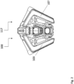
- the running light 100 is shown as part of a headlamp 117 in Fig. 1 , which also contains a low beam 119 and a high beam 121, which is connected to the running light 100 by a frame 123.
- the first waveguide 103 is enclosed in a first cover 125 made of transparent plastic.
- the second waveguide 107 is enclosed in a second cover 127 made of transparent plastic.
- the first cover 125 has a first translucent side window 129 and the second cover 127 has a second translucent side window 131.
- the legs of which are angled slightly toward one another, and a slight upward angle of the first waveguide 103 and second waveguide 107, the light beams emitted from the first waveguide 103 and second waveguide 107 cross, as indicated by the arrows 133 and 135.
- the first waveguide 103, on the left side, can therefore be seen from the right of the running light 100, and the second waveguide 107, on the right side, can be seen from the left of the running light 100.
- the headlamp 117 is shown from above in Fig. 2 .
- the first waveguide 103 and second waveguide 107 can be easily identified therein.
- Fig. 3 shows a vehicle 300 in the form of a motorcycle.
- the vehicle 300 has a headlamp 117 that contains the running light 100 shown in Fig. 1 .
Landscapes
- Engineering & Computer Science (AREA)
- General Engineering & Computer Science (AREA)
- Mechanical Engineering (AREA)
- Non-Portable Lighting Devices Or Systems Thereof (AREA)
- Lighting Device Outwards From Vehicle And Optical Signal (AREA)
Abstract
The invention relates to a running light (100) for a vehicle (300), comprising:
- at least one light source,
- a number of first optical waveguides (103) on a first side (101),
- a number of second optical waveguides (107) on a second side (105), opposite the first side (101),
wherein one of the first waveguides (103) is configured to emit light from the at least one light source in both the main beam direction, which runs along a main axis (109) orthogonal to a secondary axis (111) connecting the first side (101) and second side (105), as well as in a first area (113) toward the number of second waveguides (107), and wherein the second waveguide (107) is configured to emit the light from the at least one light source in both the main beam direction and in a second area (115) toward the number of first waveguides (103).
- at least one light source,
- a number of first optical waveguides (103) on a first side (101),
- a number of second optical waveguides (107) on a second side (105), opposite the first side (101),
wherein one of the first waveguides (103) is configured to emit light from the at least one light source in both the main beam direction, which runs along a main axis (109) orthogonal to a secondary axis (111) connecting the first side (101) and second side (105), as well as in a first area (113) toward the number of second waveguides (107), and wherein the second waveguide (107) is configured to emit the light from the at least one light source in both the main beam direction and in a second area (115) toward the number of first waveguides (103).
Description
- The present invention relates to a running light for a vehicle, a headlamp, and a vehicle according to the claims.
- Due to traffic regulations, running lights must emit light in a main beam direction, e.g. along a road, as well as to the side, e.g. right and left of the road, or the periphery of the road.
- The beam angle of a running light, or running lights, should illuminate at an angle 80° to the main beam direction, such that the running light can be readily seen from a position to the side of the vehicle.
- Existing running lights, or side marker lights, are optimized for one side of a vehicle, and emit light in a main beam direction and to a single side. Consequently, two running lights normally work together to emit light at both sides.
- Furthermore, there is limited installation space on motorcycles.
- The object of the present invention is to create a compact and reliable running light for a vehicle.
- A running light for a vehicle is therefore proposed in a first aspect of the invention.
- This running light contains at least one light source, a number of first optical waveguides on a first side, and a number of second optical waveguides on a second, opposite side, in which one of the first waveguides is configured to emit light from the at least one light source in both the main beam direction, which runs along a main axis that is orthogonal to a secondary axis connecting the first and second side, as well as in an area toward the number of second waveguides, and a second waveguide is configured to emit light from the at least one light source in both the main beam direction and in a second area toward the number of first waveguides.
- This running light, which can be a side marker light, for example, contains numerous optical waveguides, at least some of which are opposite one another.
- The individual optical waveguides in the proposed running light emit light in a main beam direction, e.g. toward the front, or along a road, and to one side, in a lateral beam direction, or lateral beam area. Some of the waveguides emit light laterally toward an opposite waveguide, such that the proposed running light emits light in the main beam direction and toward both sides, such that it can be seen from the front and both sides.
- The lateral light beams from the first and second waveguides can cross. In this case, the first and second waveguides are designed and placed in relation to one another such that the light beams emitted from the first and second waveguides cross through the middle of the running light.
- To ensure that the running light can be easily seen from the side, the waveguides therein illuminate the area on both sides of the main beam direction. This means that the running light, or the light beams thereof, can be seen from anywhere to the side thereof.
- To ensure that the proposed running light can be seen from both sides while occupying a limited installation space, the optical waveguides are placed and configured such that lateral light beams from the waveguides cross, in particular two dimensionally. These waveguides thus emit light to the side, toward the inside, e.g. toward the middle of the running light. These waveguides can be angled toward one another in particular, such that they emit light beams angled laterally, which thus cross through one another.
- Alternatively, the waveguides in the running light can be configured to emit the lateral light beams parallel to one another, in opposite directions.
- Consequently, instead of being able to see the waveguide on the respective side of the running light, the wave guide on the other side can be seen. This means that a cover on the running light, or the respective waveguides in the running light, slopes laterally downward and can therefore be more aerodynamic.
- Furthermore, the running light, or the waveguides, can be placed such that they rise toward the middle, resulting in an illuminating surface that can be readily seen from the side. This running light can therefore be shaped such that its highest point is at the center, and its lowest point is at both ends.
- The waveguides can also be angled such that the light beams they emit pass over or under the opposite waveguides.
- Furthermore, the distance between the first and second waveguides can be less than or equal to 75 mm.
- With a spacing of less than or equal to 75 mm between numerous luminous elements, or waveguides, they form an assembly having the appearance of a single running light.
- The first and second areas between the main beam direction and their respective outer boundaries each span an angle of at least 80° to the main beam direction.
- Areas spanning an angle of 80° satisfy legal requirements for running lights, thus resulting in a proposed running light suitable for use in traffic.
- Each optical waveguide can have a dedicated light source.
- A particularly bright and potentially independent lighting of the waveguides can be obtained using numerous light sources for numerous waveguides. More complex patterns can also be obtained with numerous light sources, e.g. with which only one side is lit, or can be seen as lit.
- This running light can emit light in the main beam direction and over at least 80° to both sides when it is in use.
- By lighting both sides over at least 80°, an arc of at least 160° is lit by the running light, resulting in it being visible over a broad area.
- A first optical waveguide can have a structured surface that conducts light to a first area, while a second waveguide can have a structured surface that conducts light to a second area.
- To conduct light laterally into a first area, the structured surface can comprise numerous strips or cuboids, which diffract the beams and conduct or concentrate them into the first area. There can be numerous strips, for example, interspersed with flat sections.
- The running light can also have just one first and one second waveguide, the first of which comprises a first primary area and a first secondary area, while the second comprises a second primary area and second secondary area, the first primary area of which is configured to emit light from the at least one light source in both the main beam direction and in the first area toward the second waveguide, while the second waveguide is configured to emit light in both the main beam direction and in the second area toward the first waveguide, while the first and second secondary waveguides are configured to emit light from the at least one light source only along the main beam direction.
- A complex light geometry with numerous lighting areas with different beam characteristics can be obtained with only a few waveguides, which have individual areas configured to emit light that can be seen from the side.
- A second aspect of the invention relates to a headlamp that comprises both a high beam and low beam, in addition to the running light.
- A headlamp containing the running light obtained with the invention can be particularly compact while still satisfying all of the legal requirements for lights used in traffic.
- This headlamp can be designed for use with motorcycles.
- The compact running light results in a headlamp that is ideal for motorcycles. This headlamp can be particularly aerodynamic, due to the running light obtained with the invention, i.e. particular compact and/or streamlined, thus optimizing driving stability for the motorcycle.
- A third aspect of the invention relates to a vehicle that has one of the possible designs for the proposed running light. This vehicle can be a motorcycle in particular.
- Advantages described in reference to the first aspect of the invention relating to a running light for a vehicle also apply equally to the headlamp obtained with the second aspect of the invention, and to the vehicle obtained with the third aspect of the invention.
- The invention shall be explained below in greater detail in reference to the schematic drawings. Therein:
- Figure 1
- shows one possible design for the proposed headlamp, with one possible design for the proposed running light;
- Figure 2
- shows another view of the proposed headlamp; and
- Figure 3
- shows one possible design for the proposed vehicle.
- The
running light 100 contains a light source (not shown), a firstoptical waveguide 103 on thefirst side 101, and a secondoptical waveguide 107 on thesecond side 105, opposite thefirst side 103. - The
first waveguide 103 is configured to emit light from the first light source in both a main beam direction that runs along amain axis 109 orthogonal to asecondary axis 111 connecting thefirst side 101 andsecond side 105, and in afirst area 113 toward thesecond waveguide 107. - The light source can emit light parallel to the
main axis 109 and in an area over an angle of 5° to 25° to themain axis 109. - The
second waveguide 107 is configured to emit light from the first light source in both the main beam direction and in asecond area 115 toward thefirst waveguide 103. - The running
light 100 is shown as part of aheadlamp 117 inFig. 1 , which also contains alow beam 119 and ahigh beam 121, which is connected to the runninglight 100 by aframe 123. - The
first waveguide 103 is enclosed in afirst cover 125 made of transparent plastic. Thesecond waveguide 107 is enclosed in asecond cover 127 made of transparent plastic. - The
first cover 125 has a firsttranslucent side window 129 and thesecond cover 127 has a secondtranslucent side window 131. - Because of the L-shaped form of the
first waveguide 103 andsecond waveguide 107, the legs of which are angled slightly toward one another, and a slight upward angle of thefirst waveguide 103 andsecond waveguide 107, the light beams emitted from thefirst waveguide 103 andsecond waveguide 107 cross, as indicated by thearrows - The
first waveguide 103, on the left side, can therefore be seen from the right of therunning light 100, and thesecond waveguide 107, on the right side, can be seen from the left of therunning light 100. - The
headlamp 117 is shown from above inFig. 2 . Thefirst waveguide 103 andsecond waveguide 107 can be easily identified therein. -
Fig. 3 shows avehicle 300 in the form of a motorcycle. Thevehicle 300 has aheadlamp 117 that contains the runninglight 100 shown inFig. 1 . -
- 100
- running light
- 101
- first side
- 103
- first optical waveguide
- 105
- second side
- 107
- second optical waveguide
- 109
- main axis
- 111
- secondary axis
- 113
- first area
- 115
- second area
- 117
- headlamp
- 119
- low beam
- 121
- high beam
- 123
- frame
- 125
- first cover
- 127
- second cover
- 129
- first side window
- 131
- second side window
- 133
- arrow
- 135
- arrow
- 300
- vehicle
Claims (11)
- A running light (100) for a vehicle (300), comprising:- at least one light source,- a number of first optical waveguides (103) on a first side (101), and- a number of second optical waveguides (107) on a second side (105), opposite the first side (101),wherein one of the first waveguides (103) is configured to emit light from the at least one light source in both the main beam direction, which runs along a main axis (109) orthogonal to a secondary axis (111) connecting the first side (101) and second side (105), as well as in a first area (113) toward the number of second waveguides (107), and wherein the second waveguide (107) is configured to emit the light from the at least one light source in both the main beam direction and in a second area (115) toward the number of first waveguides (103).
- The running light (100) according to claim 1, characterized in that light beams emitted laterally from the first waveguide (103) and second waveguide (107) cross one another.
- The running light (100) according to claim 1 or 2, characterized in that the distance between the number of first waveguides (103) and number of second waveguides (107) is less than or equal to 75 mm.
- The running light (100) according to any of the preceding claims, characterized in that the first area (113) and second area (115) span an angle of at least 80° between the main beam direction and an outer boundary line.
- The running light (100) according to any of the preceding claims, characterized in that the running light (100) emits light in the main beam direction and in two opposite sides, over at least 80° on each side, which face outward from the main beam direction of the running light (100).
- The running light (100) according to any of the preceding claims, characterized in that one of the first waveguides (103) has a structured surface that is designed to conduct light into the first area (113) and one of the second waveguides (107) has a structured surface that is designed to conduct light into the second area (115).
- The running light (100) according to any of the preceding claims, characterized in that the running light (100) has a single first waveguide (103) and a single second waveguide (107), wherein the first waveguide (103) has a first primary lighting area and a first secondary lighting area, wherein the second waveguide (107) has a second primary lighting area and a second secondary lighting area, wherein the first primary lighting area is designed to emit light from the at least one light source in both the main beam direction and in the first area (113), toward the second waveguide (107), wherein the second primary waveguide is designed to emit light from the at least one light source in the main beam direction and in the second area (105), toward the first waveguide, wherein the first secondary waveguide and second secondary waveguide are designed to emit light form the at least one light source only along the main beam direction.
- A headlamp (117) for a vehicle (300), wherein the headlamp (117) comprises a running light (100) according to any of the claims 1 to 7, wherein the headlamp (117) also comprises a low beam (119) and a high beam (121), in addition to the running light (100).
- The headlamp (117) according to claim 8, characterized in that the headlamp (117) is a motorcycle headlamp.
- A vehicle (300), wherein the vehicle (300) has a running light (100) according to any of the claims 1 to 7, or a headlamp (117) according to claim 8 or 9.
- The vehicle (300) according to claim 10, characterized in that the vehicle (300) is a motorcycle.
Applications Claiming Priority (1)
| Application Number | Priority Date | Filing Date | Title |
|---|---|---|---|
| DE102023129450.4A DE102023129450B4 (en) | 2023-10-25 | 2023-10-25 | Position light for a vehicle |
Publications (1)
| Publication Number | Publication Date |
|---|---|
| EP4545846A1 true EP4545846A1 (en) | 2025-04-30 |
Family
ID=93257832
Family Applications (1)
| Application Number | Title | Priority Date | Filing Date |
|---|---|---|---|
| EP24207981.2A Withdrawn EP4545846A1 (en) | 2023-10-25 | 2024-10-22 | Driving lights for a vehicle |
Country Status (4)
| Country | Link |
|---|---|
| US (1) | US12607317B2 (en) |
| EP (1) | EP4545846A1 (en) |
| CN (1) | CN119879125A (en) |
| DE (1) | DE102023129450B4 (en) |
Citations (7)
| Publication number | Priority date | Publication date | Assignee | Title |
|---|---|---|---|---|
| CN202511161U (en) * | 2012-03-12 | 2012-10-31 | 浙江嘉利(丽水)工业有限公司 | Position lamp |
| JP2015133219A (en) * | 2014-01-10 | 2015-07-23 | 株式会社小糸製作所 | Vehicle lighting |
| US20160090138A1 (en) * | 2014-09-26 | 2016-03-31 | Honda Motor Co., Ltd. | Headlight structure for vehicle |
| CN105465707A (en) * | 2014-08-20 | 2016-04-06 | 光阳工业股份有限公司 | Vehicle lamp structure |
| CN107388159A (en) * | 2017-08-29 | 2017-11-24 | 上海小糸车灯有限公司 | A kind of extendable car light light guide luminescent system of width |
| EP3258166A1 (en) * | 2016-06-14 | 2017-12-20 | Honda Motor Co., Ltd. | Vehicular lighting with light guides |
| WO2020174763A1 (en) * | 2019-02-27 | 2020-09-03 | 本田技研工業株式会社 | Saddled vehicle |
Family Cites Families (2)
| Publication number | Priority date | Publication date | Assignee | Title |
|---|---|---|---|---|
| JP7246197B2 (en) * | 2019-02-08 | 2023-03-27 | 株式会社小糸製作所 | vehicle lamp |
| KR20220037645A (en) * | 2020-09-18 | 2022-03-25 | 에스엘 주식회사 | Lamp for vehicle |
-
2023
- 2023-10-25 DE DE102023129450.4A patent/DE102023129450B4/en active Active
-
2024
- 2024-10-21 US US18/921,232 patent/US12607317B2/en active Active
- 2024-10-22 EP EP24207981.2A patent/EP4545846A1/en not_active Withdrawn
- 2024-10-25 CN CN202411496691.9A patent/CN119879125A/en active Pending
Patent Citations (7)
| Publication number | Priority date | Publication date | Assignee | Title |
|---|---|---|---|---|
| CN202511161U (en) * | 2012-03-12 | 2012-10-31 | 浙江嘉利(丽水)工业有限公司 | Position lamp |
| JP2015133219A (en) * | 2014-01-10 | 2015-07-23 | 株式会社小糸製作所 | Vehicle lighting |
| CN105465707A (en) * | 2014-08-20 | 2016-04-06 | 光阳工业股份有限公司 | Vehicle lamp structure |
| US20160090138A1 (en) * | 2014-09-26 | 2016-03-31 | Honda Motor Co., Ltd. | Headlight structure for vehicle |
| EP3258166A1 (en) * | 2016-06-14 | 2017-12-20 | Honda Motor Co., Ltd. | Vehicular lighting with light guides |
| CN107388159A (en) * | 2017-08-29 | 2017-11-24 | 上海小糸车灯有限公司 | A kind of extendable car light light guide luminescent system of width |
| WO2020174763A1 (en) * | 2019-02-27 | 2020-09-03 | 本田技研工業株式会社 | Saddled vehicle |
Also Published As
| Publication number | Publication date |
|---|---|
| US12607317B2 (en) | 2026-04-21 |
| CN119879125A (en) | 2025-04-25 |
| US20250137603A1 (en) | 2025-05-01 |
| DE102023129450A1 (en) | 2025-04-30 |
| DE102023129450B4 (en) | 2025-05-15 |
Similar Documents
| Publication | Publication Date | Title |
|---|---|---|
| US7677777B2 (en) | LED apparatus for world homologation | |
| US8888343B2 (en) | Optical device and signaling and/or lighting system | |
| US6367957B1 (en) | Lighting, especially for motor vehicles | |
| US9416935B2 (en) | Vehicle direction indicator light having a light emitting body including an outer emitting surface, an inner emitting surface, a tip surface, and a light guide body | |
| US8939622B2 (en) | Signal light device for a motor vehicle | |
| US10261228B2 (en) | Vehicle lighting device with optical waveguides | |
| JP7081977B2 (en) | Vehicle lighting | |
| US11754250B2 (en) | Vehicle lamp | |
| US20160208995A1 (en) | Vehicle signal lamp | |
| CN102233844A (en) | Vehicle exterior lamp | |
| US20120250343A1 (en) | Vehicular Lamp | |
| US10520156B2 (en) | Vehicle light | |
| JP2019023965A (en) | Vehicle lighting | |
| AU2018361984B2 (en) | Headlight for a vehicle | |
| EP3572723A1 (en) | Lighting tool for vehicle | |
| JP2013122872A (en) | Illumination lamp fitting for vehicle | |
| US12607317B2 (en) | Running light for a vehicle | |
| US12117138B2 (en) | Beamshaping waveguide for headlights | |
| KR20170079257A (en) | Lamp for vehicle | |
| US11300265B2 (en) | Lamp for automobile and automobile including the same | |
| JP2019139934A (en) | Lighting appliance for vehicle | |
| CN114251624A (en) | Lighting device for a motor vehicle headlight for generating a basic light distribution with an indicator light | |
| CN219346279U (en) | Light guide assembly, lamp device and motor vehicle | |
| CN219530642U (en) | Optical assembly, lighting device and motor vehicle | |
| JP7390244B2 (en) | Vehicle lights |
Legal Events
| Date | Code | Title | Description |
|---|---|---|---|
| PUAI | Public reference made under article 153(3) epc to a published international application that has entered the european phase |
Free format text: ORIGINAL CODE: 0009012 |
|
| STAA | Information on the status of an ep patent application or granted ep patent |
Free format text: STATUS: THE APPLICATION HAS BEEN PUBLISHED |
|
| AK | Designated contracting states |
Kind code of ref document: A1 Designated state(s): AL AT BE BG CH CY CZ DE DK EE ES FI FR GB GR HR HU IE IS IT LI LT LU LV MC ME MK MT NL NO PL PT RO RS SE SI SK SM TR |
|
| RAP3 | Party data changed (applicant data changed or rights of an application transferred) |
Owner name: HELLA GMBH & CO. KGAA |
|
| STAA | Information on the status of an ep patent application or granted ep patent |
Free format text: STATUS: THE APPLICATION IS DEEMED TO BE WITHDRAWN |
|
| 18D | Application deemed to be withdrawn |
Effective date: 20251031 |