EP4545837A1 - Fluid leakage detection system and method for marine hose - Google Patents
Fluid leakage detection system and method for marine hose Download PDFInfo
- Publication number
- EP4545837A1 EP4545837A1 EP22948059.5A EP22948059A EP4545837A1 EP 4545837 A1 EP4545837 A1 EP 4545837A1 EP 22948059 A EP22948059 A EP 22948059A EP 4545837 A1 EP4545837 A1 EP 4545837A1
- Authority
- EP
- European Patent Office
- Prior art keywords
- tag
- fluid
- hose
- resistance value
- communication unit
- Prior art date
- Legal status (The legal status is an assumption and is not a legal conclusion. Google has not performed a legal analysis and makes no representation as to the accuracy of the status listed.)
- Pending
Links
Images





Classifications
-
- F—MECHANICAL ENGINEERING; LIGHTING; HEATING; WEAPONS; BLASTING
- F16—ENGINEERING ELEMENTS AND UNITS; GENERAL MEASURES FOR PRODUCING AND MAINTAINING EFFECTIVE FUNCTIONING OF MACHINES OR INSTALLATIONS; THERMAL INSULATION IN GENERAL
- F16L—PIPES; JOINTS OR FITTINGS FOR PIPES; SUPPORTS FOR PIPES, CABLES OR PROTECTIVE TUBING; MEANS FOR THERMAL INSULATION IN GENERAL
- F16L11/00—Hoses, i.e. flexible pipes
- F16L11/04—Hoses, i.e. flexible pipes made of rubber or flexible plastics
- F16L11/12—Hoses, i.e. flexible pipes made of rubber or flexible plastics with arrangements for particular purposes, e.g. specially profiled, with protecting layer, heated, electrically conducting
-
- F—MECHANICAL ENGINEERING; LIGHTING; HEATING; WEAPONS; BLASTING
- F16—ENGINEERING ELEMENTS AND UNITS; GENERAL MEASURES FOR PRODUCING AND MAINTAINING EFFECTIVE FUNCTIONING OF MACHINES OR INSTALLATIONS; THERMAL INSULATION IN GENERAL
- F16L—PIPES; JOINTS OR FITTINGS FOR PIPES; SUPPORTS FOR PIPES, CABLES OR PROTECTIVE TUBING; MEANS FOR THERMAL INSULATION IN GENERAL
- F16L11/00—Hoses, i.e. flexible pipes
- F16L11/04—Hoses, i.e. flexible pipes made of rubber or flexible plastics
- F16L11/12—Hoses, i.e. flexible pipes made of rubber or flexible plastics with arrangements for particular purposes, e.g. specially profiled, with protecting layer, heated, electrically conducting
- F16L11/133—Hoses, i.e. flexible pipes made of rubber or flexible plastics with arrangements for particular purposes, e.g. specially profiled, with protecting layer, heated, electrically conducting buoyant
-
- G—PHYSICS
- G01—MEASURING; TESTING
- G01M—TESTING STATIC OR DYNAMIC BALANCE OF MACHINES OR STRUCTURES; TESTING OF STRUCTURES OR APPARATUS, NOT OTHERWISE PROVIDED FOR
- G01M3/00—Investigating fluid-tightness of structures
- G01M3/02—Investigating fluid-tightness of structures by using fluid or vacuum
- G01M3/04—Investigating fluid-tightness of structures by using fluid or vacuum by detecting the presence of fluid at the leakage point
- G01M3/16—Investigating fluid-tightness of structures by using fluid or vacuum by detecting the presence of fluid at the leakage point using electric detection means
- G01M3/18—Investigating fluid-tightness of structures by using fluid or vacuum by detecting the presence of fluid at the leakage point using electric detection means for pipes, cables or tubes; for pipe joints or seals; for valves; for welds; for containers, e.g. radiators
- G01M3/182—Investigating fluid-tightness of structures by using fluid or vacuum by detecting the presence of fluid at the leakage point using electric detection means for pipes, cables or tubes; for pipe joints or seals; for valves; for welds; for containers, e.g. radiators for tubes
-
- F—MECHANICAL ENGINEERING; LIGHTING; HEATING; WEAPONS; BLASTING
- F16—ENGINEERING ELEMENTS AND UNITS; GENERAL MEASURES FOR PRODUCING AND MAINTAINING EFFECTIVE FUNCTIONING OF MACHINES OR INSTALLATIONS; THERMAL INSULATION IN GENERAL
- F16L—PIPES; JOINTS OR FITTINGS FOR PIPES; SUPPORTS FOR PIPES, CABLES OR PROTECTIVE TUBING; MEANS FOR THERMAL INSULATION IN GENERAL
- F16L2201/00—Special arrangements for pipe couplings
- F16L2201/30—Detecting leaks
Definitions
- the present invention relates to a fluid leakage detection system and method for a marine hose and particularly relates to a fluid leakage detection system and method for a marine hose that can accurately detect the presence or absence of fluid leakage in various types of marine hoses.
- fluid leaked from a flow path is temporarily stored in a fluid retention layer formed between reinforcing layers formed with an interval therebetween in a hose radial direction to prevent leakage outside the hose.
- a known fluid leakage detection system detects fluid leakage using an IC tag disposed in this fluid retention layer (for example, see Patent Document 1).
- Patent Document 1 JP 2020-133766 A
- An object of the present invention is to provide a fluid leakage detection system and method for a marine hose that can accurately detect the presence or absence of fluid leakage in various types of marine hoses.
- a fluid leakage detection system for a marine hose is a fluid leakage detection system for a marine hose provided with a hose body including a reinforcing layer and a buoyant layer layered in this order from an inner circumferential side between an inner surface layer and an outer surface layer and connection fittings connected to both respective ends of the hose body in a longitudinal direction, the inner surface layer including an inner circumferential region as a flow path.
- the fluid leakage detection system includes: the marine hose; a detector including an IC tag that is passive and a loop circuit formed of a detection element connected to the IC tag; a communication unit disposed outside the marine hose and configured to wirelessly communicate with the IC tag; and a computation device into which obtained data from the communication unit is input.
- the IC tag is disposed on a surface of the marine hose.
- the detection element is formed of conductive rubber or conductive paste whose electrical resistance value changes to a value equal to or greater than a preset reference by being impregnated with fluid flowing through the flow path, the detection element continuously extending in the longitudinal direction of the hose body between the inner surface layer and the reinforcing layer.
- the IC tag is activated by transmission radio waves transmitted from the communication unit, return radio waves is transmitted from the IC tag activated in response to the transmission radio waves, and thus wireless communication between the IC tag and the communication unit is performed.
- Electrical resistance value data at the loop circuit when the IC tag is activated is transmitted from the IC tag to the communication unit via the return radio waves and is input into the computation device as the obtained data, and presence or absence of leakage of the fluid from the flow path is determined by the computation device in accordance with a magnitude of a difference between the obtained data input and preset reference resistance value data.
- a fluid leakage detection method for a marine hose is a fluid leakage detection method for a marine hose provided with a hose body including a reinforcing layer and a buoyant layer layered in this order from an inner circumferential side between an inner surface layer and an outer surface layer and connection fittings connected to both respective ends of the hose body in a longitudinal direction, the inner surface layer including an inner circumferential region as a flow path.
- the fluid leakage detection method includes: using a detector including an IC tag that is passive and a loop circuit formed of a detection element connected to the IC tag, a communication unit disposed outside the marine hose and configured to wirelessly communicate with the IC tag, and a computation device into which obtained data from the communication unit is input; disposing the IC tag on a surface of the marine hose, forming the detection element of conductive rubber or conductive paste whose electrical resistance value changes to a value equal to or greater than a preset reference by being impregnated with fluid flowing through the flow path, and continuously extending the detection element in the longitudinal direction of the hose body between the inner surface layer and the reinforcing layer; activating the IC tag with transmission radio waves transmitted from the communication unit, transmitting return radio waves from the IC tag to the communication unit in response to the transmission radio waves, thus performing wireless communication between the IC tag and the communication unit, transmitting electrical resistance value data at the loop circuit when the IC tag is activated from the IC tag to the communication unit via the return radio waves,
- the detector is installed in the marine hose by disposing the IC tag on the surface of the marine hose and continuously extending the loop circuit in the longitudinal direction of the marine hose between the inner surface layer and the reinforcing layer.
- This allows the detector to be installed in both a so-called single carcass type and double carcass type. Then, when the fluid leaks from the flow path to the outer circumferential side of the inner surface layer and impregnates the detection element forming the loop circuit, an electrical resistance value at the loop circuit when the IC tag is activated by the transmission radio waves greatly changes to be equal to or greater than a preset reference.
- the presence or absence of leakage of the fluid from the flow path can be accurately determined on the basis of the magnitude of the difference between the electrical resistance value data input to the computation device as the obtained data and the preset reference resistance value data. Since the electrical resistance value data can be obtained via wireless communication using the return radio waves transmitted from the passive IC tag to the communication unit in response to the transmission radio waves from the communication unit, it greatly contributes to reduction in labor for checking the fluid leakage.
- a fluid leakage detection system (hereinafter referred to as a detection system) and method for a marine hose according to an embodiment of the present invention will be described with reference to the drawings.
- the detection system according to an embodiment illustrated in FIG. 1 is applied to a floating type marine hose 1 used in a state where it floats on the water surface and is configured to detect the presence or absence of leakage of a fluid L from a flow path 1a.
- the marine hose 1 includes a cylindrical hose body and connection fittings 2 connected to both ends of the hose body in a longitudinal direction.
- the connection fittings 2 each includes a nipple 2b extending in the longitudinal direction of the hose body and a flange 2a joined to one end of the nipple 2b in the longitudinal direction.
- the marine hoses 1 are connected to each other through the connection fittings 2, and generally about ten marine hoses 1 are connected and used.
- an inner surface layer 3 a first reinforcing layer 4, a buoyant layer 8, and an outer surface layer 9 are layered in this order from the inner circumferential side to the outer circumferential side. Since the hose body does not include a fluid retention layer 7 described below, the marine hose 1 is a single carcass type.
- the inner circumferential side of the inner surface layer 3 serves as the flow path 1a of the fluid L. Examples of the fluid L include crude oil, heavy oil, gasoline, LPG, water, seawater, chemicals (alcohols refined from gasoline), and the like.
- the inner surface layer 3 is formed of a material having excellent durability and corrosion resistance to the fluid L.
- the inner surface layer 3 is formed of nitrile rubber or the like having an excellent oil resistance.
- the first reinforcing layer 4 includes a plurality of layers of reinforcing cord layers 4A to 4H formed of multiple reinforcing cords arranged side by side and covered with rubber.
- one reinforcing cord layer group of eight reinforcing cord layers 4A to 4H layered together corresponds to the first reinforcing layer 4, but the number of layers of the reinforcing cord layers 4A to 4H is appropriately determined on the basis of the required performance of the marine hose 1.
- the first reinforcing layer 4 is fixed to each nipple 2b using nipple wires 4w at both end portions and a fixing ring 2c or the like disposed projecting out on the outer circumferential surface of each nipple 2b.
- the buoyant layer 8 is formed of a material such as sponge rubber, polyurethane foam or the like that exhibits buoyancy to float the marine hose 1 above the sea.
- the outer surface layer 9 is formed of a non-water-permeable material such as rubber, and has a line pattern or the like having excellent visibility on the surface thereof.
- the detection system includes the marine hose 1, a detector 10, a communication unit 19, and a computation device 20.
- the communication unit 19 is separate from the marine hose 1 and is disposed on the outside of the marine hose 1.
- the communication unit 19 and the computation device 20 are integrally formed, but a configuration can be used in which they are separate and independent.
- the detector 10 includes a passive IC tag 11 and a loop circuit 17 connected to the IC tag 11.
- the IC tag 11 is disposed on the surface of the marine hose 1 and positioned on the water.
- the loop circuit 17 is formed by a detection element 15 and extends continuously in the longitudinal direction of the hose body between the inner surface layer 3 and the first reinforcing layer 4.
- the IC tag 11 includes an IC chip 12 and an antenna unit 13 connected to the IC chip 12.
- the IC chip 12 and the antenna unit 13 are disposed on a substrate 14.
- the IC chip 12 and the antenna unit 13 are covered with an insulating layer 14a, and the entire IC tag 11 is electrically insulated from the outside.
- the IC tag 11 and the detection element 15 are electrically conductively connected to each other.
- the insulating layer 14a is formed of a known insulating material such as insulating rubber, resins such as polyester, and natural fibers.
- the IC chip 12 arbitrarily stores tag unique information such as an identification number of the IC tag 11, element identification information for specifying the detection element 15 connected to the IC tag 11, and other necessary information.
- tag unique information such as an identification number of the IC tag 11, element identification information for specifying the detection element 15 connected to the IC tag 11, and other necessary information.
- various types of known antennas can be used as the antenna unit 13, a dipole antenna extending left-right symmetrically from the IC chip 12 is employed in this embodiment.
- the antenna unit 13 is appropriately folded back so as to increase the extension length in a limited space.
- the commonly distributed specifications are adopted for the IC tag 11, and for example, an RFID tag can be used.
- the IC chip 12 has a very small size, for example, a vertical dimension and a horizontal dimension of 50 mm or less (corresponding to an outer diameter of 50 mm or less) and a thickness of 5 mm or less.
- the size of the antenna unit 13 is also very small, for example, the vertical dimension and the horizontal dimension are each 50 mm or less (corresponding to an outer diameter of 50 mm or less) and the thickness is 10 mm or less.
- the detection element 15 is a linear member with electrical conductivity and is formed of conductive rubber or conductive paste (paste containing metal particles) whose electrical resistance value changes to a value equal to or greater than a preset reference by being impregnated with the fluid L flowing through the flow path 1a. If the difference in the electrical resistance value of the detection element 15 depending on presence or absence of impregnation with the fluid L is too small, the sensitivity for detecting leakage of the fluid L is decreased. Thus, preferably, the difference in the electrical resistance value of the detection element 15 is larger when the detection element 15 is impregnated with the fluid L compared to when the detection element 15 is not impregnated.
- the electrical resistance value per unit length in a unit cross-sectional area of the detection element 15 when impregnated with the fluid L is set to, for example, twice or more, preferably three times or more, and more preferably five times or more of the reference electrical resistance value per unit length in a unit cross-sectional area of the detection element 15 in a state in which it is not impregnated with the fluid L.
- the electrical resistance value in the case of impregnation with the fluid L is a value measured in a state in which the fluid L adheres to the entire outer circumferential surface of the detection element 15 in a linear state.
- the content ratio between the conductive component and the insulating component of the detection element 15 is adjusted.
- the electrical resistance value of the detection element 15 is increased to some extent. Thus, it becomes unclear whether the change in the electrical resistance value of the detection element 15 is caused by the impregnation of the detection element 15 with the fluid L or the bending of the detection element 15.
- the difference in the electrical resistance value in the case where the detection element 15 is bent is smaller than the difference in the case where the detection element 15 is not bent.
- the electrical resistance value per unit length in a unit cross-sectional area of the detection element 15 in a bent state is set to, for example, 1.5 times or less, preferably 1.3 times or less, and more preferably 1.1 times or less of the reference electrical resistance value per unit length in a unit cross-sectional area of the detection element 15 in a linear state.
- the electrical resistance value in a state in which the detection element 15 is bent is a value measured in a state in which the detection element 15 is bent by 90°. In order to make the electrical resistance value of the detection element 15 in a bent state equal to or less than the preset reference value as described above, for example, the content ratio of the elasticity component of the detection element 15 is adjusted.
- the detection element 15 has an outer diameter (width) ranging from, for example, 1 mm to 20 mm and preferably from 5 mm to 10 mm.
- the detection element 15 is preferably a simple wire having a circular cross-section but may be a flat linear member (band-like wire).
- the outer circumferential surface of the detection element 15 is covered with an insulator 16, and the detection element 15 is electrically insulated from the outside.
- the insulator 16 is formed of a known insulating material in a similar manner as the insulating layer 14a. However, the insulator 16 is formed of a material through which the fluid L permeates or includes a through-hole so that the fluid L can pass through the insulator 16 and reach the detection element 15.
- One end portion and the other end portion of the detection element 15 in the longitudinal direction are electrically connected to the IC chip 12, forming the loop circuit 17 outside the IC tag 11.
- the interval between the detection elements 15 extending in parallel in the loop circuit 17 is, for example, 5 mm or more and 50 mm or less.
- the IC tag 11 (the substrate 14) is provided with a large number of pairs of terminals connected to the IC chip 12.
- Each of one end portion and the other end portion of the detection element 15 in the longitudinal direction is connected to the pair of terminals and thus is electrically connected to the IC chip 12.
- the detection element 15 and the pair of terminals are connected by using an eyelet and a crimp terminal or by using a conductive adhesive, welding, solder, or the like.
- the number of pairs of terminals provided on the IC tag 11 (the substrate 14) is not particularly limited and may be one pair of terminals. Since a space is restricted, the number of pairs of terminals provided on one IC tag 11 (substrate 14) is, for example, about one to six pairs of terminals.
- the IC tag 11 is preferably disposed at a longitudinal end portion of the marine hose 1.
- the loop circuit 17 (detection element 15) preferably extends continuously from one end portion to the other end portion in the longitudinal direction of the hose body so as to cover the entire length of the hose body.
- the IC tag 11 is disposed on the surface (outer circumferential surface of the nipple 2b) of the connection fitting 2 at one end portion of the hose body in the longitudinal direction.
- the IC tag 11 is disposed inside a casing 18.
- the casing 18 includes a cylindrical base portion 18a and a cover portion 18b attached to an upper end portion of the base portion 18a.
- the base portion 18a is erected on the outer circumferential surface of the nipple 2b covered with the outer surface layer 9.
- the base portion 18a is formed of, for example, stainless steel or a similar metal.
- the cover portion 18b is screwed to the upper end portion of the base portion 18a to watertightly close the upper end opening, and the IC tag 11 is disposed in the watertightly closed internal space of the casing 18.
- the cover portion 18b is formed of a material that allows transmission radio waves R1 and return radio waves R2 to pass through, this material being, for example, polycarbonate, polyamide, epoxy resin, or the like.
- the casing 18 (cover portion 18b) may be orange so as to be noticeable in the ocean, for example.
- the detection element 15 extends from the inside of the casing 18 toward the hose body, is disposed between the inner surface layer 3 and the first reinforcing layer 4 in the hose body, and extends continuously from one end portion to the other end portion in the longitudinal direction of the hose body.
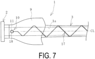
- the loop circuit 17 is spirally wound around the hose body and extends from one end portion to the other end portion in the longitudinal direction of the hose body. That is, the loop circuit 17 is spirally wound around the outer circumferential surface of the inner surface layer 3.
- the spiral pitch of the loop circuit 17 is, for example, 20 cm or more and 50 cm or less.
- a dot-dash line CL in the diagram is an axial center passing through a cross-sectional center CL of the marine hose 1 (hose body).
- the communication unit 19 includes a radio wave transmission unit 19a and a radio wave reception unit 19b.
- the radio wave transmission unit 19a transmits the transmission radio waves R1 to the IC tag 11, and the radio wave reception unit 19b receives the return radio waves R2 transmitted from the IC tag 11.
- the IC tag 11 is activated by the transmission radio waves R1, and the return radio waves R2 are transmitted from the activated IC tag 11 in response to the transmission radio wave R2, whereby wireless communication is performed between the IC tag 11 and the communication unit 19.
- the IC tag 11 and the communication unit 19 constitute a radio frequency identification (RFID) system. Since the passive type IC tag 11 is used, the communication distance of the radio waves R1 and R2 between the IC tag 11 and the communication unit 19 is, for example, several tens of centimeters or more and several meters or less.
- RFID radio frequency identification
- the frequency of radio waves (R1 and R2) used for wireless communication between the IC tag 11 and the communication unit 19 is mainly in the UHF band (depending on the country, in a range of 860 MHz or more and 930 MHz or less, in a range of 915 MHz or more and 930 MHz or less in Japan), and the HF band (13.56 MHz) may be used.
- a monitor or the like may be attached to the communication unit 19, for example.
- the computation device 20 performs various computational processing using the input data.
- a known computer is used as the computation device 20, and reference resistance value data Dc is input to the computation device 20 in advance.
- the reference resistance value data Dc is an electrical resistance value at the loop circuit 17 when the IC tag is activated in a sound state of the marine hose 1 in which the fluid L is not leaking from the flow path 1a.
- the reference resistance value data Dc is obtained and determined by performing a preliminary test or the like.
- Data obtained by the communication unit 19 is also input to the computation device 20.
- An output unit such as a monitor is connected to the computation device 20.
- the transmission radio waves R1 are transmitted from the radio wave transmission unit 19a toward the IC tag 11, and the transmission radio waves R1 are used to generate electric power to activate the IC tag 11.
- Electric power is generated in the IC tag 11 by the transmission radio waves R1 received by the antenna unit 13, and the IC tag 11 is activated.
- the activated IC tag 11 transmits the return radio waves R2 by the electric power via the antenna unit 13, and the return radio waves R2 are received by the radio wave reception unit 19b.
- a current flows through the loop circuit 17, and electrical resistance value data Dr of the loop circuit 17 is stored in the IC tag 11.
- the electrical resistance value data Dr is transmitted from the IC tag 11 to the communication unit 19 by the return radio waves R2.
- the electrical resistance value data Dr is received by the radio wave reception unit 19b and thereafter inputted to the computation device 20 as obtained data by the communication unit 19.
- the computation device 20 determines presence or absence of a leakage of the fluid L from the flow path 1a on the basis of the magnitude of the difference between the input electrical resistance value data Dr and the preset reference resistance value data Dc.
- the electrical resistance value data Dr of the loop circuit 17 and the reference resistance value data Dc are substantially the same and have almost no difference.
- the electrical resistance value data Dr of the loop circuit 17 when the IC tag 11 is activated becomes significantly larger than the reference resistance value data Dc.
- the computation device 20 compares the input electrical resistance value data Dr with the reference resistance value data Dc. As a result, when the electrical resistance value data Dr is greater than the reference resistance value data Dc and exceeds a tolerance range AR, it is determined that the fluid L is leaking from the flow path 1a. This result is then communicated via a monitor display or audio. When the difference between the electrical resistance value data Dr and the reference resistance value data Dc is within the tolerance range AR, it is determined that the fluid L is not leaking from the flow path 1a. This result is then communicated via a monitor display, for example.
- the tolerance range AR may be appropriately set by performing a preliminary test or the like. According to this embodiment, it is possible to accurately detect a minute leak in which the inner surface layer 3 is cracked and the fluid L gradually leaks out through the outer circumferential surface of the inner surface layer 3.
- the computation device 20 can also be configured to connect to a terminal device such as a computer or a smartphone located at a position (remote location) away from the use site of the marine hose 1 via a communication network such as the Internet. According to this configuration, the computation device 20 can transmit the electrical resistance value data Dr and the determination result (presence or absence of leakage of the fluid L) by the computation device 20 to the terminal device located at a position away from the use site of the marine hose 1 through the communication network.
- a terminal device such as a computer or a smartphone located at a position (remote location) away from the use site of the marine hose 1 via a communication network such as the Internet.
- the computation device 20 can transmit the electrical resistance value data Dr and the determination result (presence or absence of leakage of the fluid L) by the computation device 20 to the terminal device located at a position away from the use site of the marine hose 1 through the communication network.
- the electrical resistance value data Dr and the determination result by the computation device 20 are transmitted to a terminal device of a related person in management of an operating company (user) of the marine hose 1, a sales company of the marine hose 1, or a manufacturing company of the marine hose 1 at a remote location with respect to the use site of the marine hose 1.
- This allows the related person to obtain the state of the marine hose 1 while being at the remote location with respect to the use site of the marine hose 1.
- the detector 10 illustrated in FIG. 8 may be used.
- the detector 10 is configured such that a plurality of (four) detection elements 15a, 15b, 15c, and 15d are connected to one IC tag 11.
- the outer circumferential surface of each of the detection elements 15a, 15b, 15c, and 15d is covered by the insulator 16.
- the detection elements 15a, 15b, 15c, and 15d respectively form independent loop circuits 17a, 17b, 17c, and 17d.
- the plurality of (four) independent loop circuits 17a to 17d are connected to one IC tag 11.
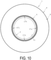
- the independent loop circuits 17a to 17d are disposed at intervals in the circumferential direction with respect to the hose body and linearly extend in the longitudinal direction of the hose body.
- the loop circuits 17a to 17d are preferably disposed at regular intervals in a circumferential direction of the hose body.
- this detector 10 has an advantage that even if one loop circuit 17 fails for some reason, the presence or absence of leakage of the fluid L can be detected by the other loop circuits 17.
- the total length of each of the loop circuits 17a to 17d can be shortened, compared to a case where the loop circuit 17 extends in a spiral shape, there is an advantage in that a change in the electrical resistance value at each of the loop circuits 17a to 17d can be detected with more sensitivity (higher sensitivity).
- the loop circuits 17a to 17d may be shifted in the longitudinal direction of the hose body and spirally wound around the hose body so as to extend.
- the detection system described above can be applied not only to the marine hose 1 of a single carcass type but also to the marine hose 1 of a double carcass type including the fluid retention layer 7 in the hose body.
- the inner surface layer 3, the first reinforcing layer 4, a body wire layer 5, the fluid retention layer 7, a second reinforcing layer 6, the buoyant layer 8, and the outer surface layer 9 are layered in this order from the inner circumferential side to the outer circumferential side.
- the marine hose 1 is a double carcass type including the first reinforcing layer 4 and the second reinforcing layer 6 layered with an interval therebetween in the radial direction of a hose body and the fluid retention layer 7 interposed therebetween.
- the body wire layer 5 can be discretionarily provided.
- the first reinforcing layer 4 and the second reinforcing layer 6 each include a plurality of layers of reinforcing cord layers formed of multiple reinforcing cords arranged side by side and covered with rubber.
- the body wire layer 5 is configured by spirally winding metal wires around the outer circumferential surface of the first reinforcing layer 4 at predetermined intervals.
- the first reinforcing layer 4, the body wire layer 5, and the second reinforcing layer 6 are fixed to each nipple 2b using nipple wires 4w, 5w, and 6w at both end portions and a fixing ring 2c or the like disposed projecting out on the outer circumferential surface of each nipple 2b at both end portions of the hose body.
- the fluid retention layer 7 formed between the first reinforcing layer 4 and the second reinforcing layer 6 is a space for storing the fluid L that has leaked from the flow path 1a.
- the loop circuit 17 is disposed inside the fluid retention layer 7.
- the fluid L leaks due to damage to the inner surface layer 3, passes through the body wire layer 5, and enters the fluid retention layer 7, the fluid L comes into contact with the detection elements 15 forming the loop circuit 17, and the electrical resistance value of the loop circuit 17 rapidly and largely changes (becomes extremely large), putting it in an insulating state or a state close to an insulating state. That is, the electrical resistance value data Dr of the loop circuit 17 when the IC tag 11 is activated becomes significantly larger than the reference resistance value data Dc.
- the electrical resistance value data Dr of the loop circuit 17 and the reference resistance value data Dc have almost no difference. In this manner, as described above, presence or absence of leakage of the fluid L can be accurately determined on the basis of the magnitude of the difference between the electrical resistance value data Dr received by the radio wave reception unit 19b and the reference resistance value data Dc.
- the loop circuit 17 When the fluid L flows into a part of the fluid retention layer 7, the fluid L gradually spreads over the entire length of the fluid retention layer 7. Thus, when the loop circuit 17 is disposed inside the fluid retention layer 7, the loop circuit 17 does not need to be extended so long. Thus, the loop circuit 17 is continuously extended from one end in the longitudinal direction of the hose body to a position of, for example, 20% or more and 50% or less of the entire length of the hose body.
- this marine hose 1 may have a configuration in which the loop circuit 17 is disposed on the outer circumferential surface of the inner surface layer 3.
- the loop circuit 17 When the loop circuit 17 is disposed on the outer circumferential surface of the inner surface layer 3, it preferably extends continuously from one end portion to the other end portion in the longitudinal direction of the hose body.
- the loop circuit 17 may be spirally wound around the hose body and extended or, as illustrated in FIGS. 9 and 10 , the plurality of loop circuits 17 may be disposed at intervals in the circumferential direction of the hose body and linearly extend in the longitudinal direction of the hose body.
- the detection system is highly versatile because it can be applied to both single carcass type and double carcass type marine hoses 1. Further, since the electrical resistance value data Dr can be obtained via wireless communication using the return radio waves R2 transmitted from the IC tag 11 to the communication unit 19 in response to the transmission radio waves R1 from the communication unit 19, it greatly contributes to reduction in labor for checking the fluid leakage. Since the passive IC tag 11 is used, the work of monitoring the status of the battery life of the IC tag 11 also becomes unnecessary.
Landscapes
- Engineering & Computer Science (AREA)
- General Engineering & Computer Science (AREA)
- Mechanical Engineering (AREA)
- Physics & Mathematics (AREA)
- General Physics & Mathematics (AREA)
- Rigid Pipes And Flexible Pipes (AREA)
- Pipeline Systems (AREA)
- Examining Or Testing Airtightness (AREA)
Abstract
Provided is a fluid leakage detection system and method for a marine hose that can accurately detect presence or absence of fluid leakage in various types of marine hoses. As a detection element (15) forming a loop circuit (17) connected to an IC tag (11) that is passive, conductive rubber or conductive paste whose electrical resistance value changes to a value equal to or greater than a reference by being impregnated with a fluid (L) is adopted, and the detection element (15) is caused to continuously extend in a longitudinal direction of the hose body between an inner surface layer (3) and a first reinforcing layer (4). The IC tag (11) is disposed on a surface of the marine hose (1). Electrical resistance value data (Dr) at the loop circuit (17) when the IC tag (11) is activated by transmission radio waves (R1) transmitted from a communication unit (19) is transmitted to the communication unit (19) via return radio waves (R2) transmitted from the IC tag (11) in response to the transmission radio waves (R1) and is input to the computation device (20). Presence or absence of leakage of the fluid (L) is determined in accordance with a magnitude of a difference between the electrical resistance value data (Dr) and reference resistance value data (Dc).
Description
- The present invention relates to a fluid leakage detection system and method for a marine hose and particularly relates to a fluid leakage detection system and method for a marine hose that can accurately detect the presence or absence of fluid leakage in various types of marine hoses.
- In double carcass marine hoses, fluid leaked from a flow path is temporarily stored in a fluid retention layer formed between reinforcing layers formed with an interval therebetween in a hose radial direction to prevent leakage outside the hose. A known fluid leakage detection system detects fluid leakage using an IC tag disposed in this fluid retention layer (for example, see Patent Document 1).
- However, there is also a single carcass type of marine hose that does not include a fluid retention layer. For single carcass marine hoses, it is also desirably to detect fluid leakage from the flow path, but an appropriate detection system has not been established. Thus, there is room for improvement in accurately detecting the presence or absence of fluid leakage in various types of marine hoses.
- Patent Document 1:
JP 2020-133766 A - An object of the present invention is to provide a fluid leakage detection system and method for a marine hose that can accurately detect the presence or absence of fluid leakage in various types of marine hoses.
- To achieve the object described above, a fluid leakage detection system for a marine hose according to an embodiment of the present invention is a fluid leakage detection system for a marine hose provided with a hose body including a reinforcing layer and a buoyant layer layered in this order from an inner circumferential side between an inner surface layer and an outer surface layer and connection fittings connected to both respective ends of the hose body in a longitudinal direction, the inner surface layer including an inner circumferential region as a flow path. The fluid leakage detection system includes: the marine hose; a detector including an IC tag that is passive and a loop circuit formed of a detection element connected to the IC tag; a communication unit disposed outside the marine hose and configured to wirelessly communicate with the IC tag; and a computation device into which obtained data from the communication unit is input. The IC tag is disposed on a surface of the marine hose. The detection element is formed of conductive rubber or conductive paste whose electrical resistance value changes to a value equal to or greater than a preset reference by being impregnated with fluid flowing through the flow path, the detection element continuously extending in the longitudinal direction of the hose body between the inner surface layer and the reinforcing layer. The IC tag is activated by transmission radio waves transmitted from the communication unit, return radio waves is transmitted from the IC tag activated in response to the transmission radio waves, and thus wireless communication between the IC tag and the communication unit is performed. Electrical resistance value data at the loop circuit when the IC tag is activated is transmitted from the IC tag to the communication unit via the return radio waves and is input into the computation device as the obtained data, and presence or absence of leakage of the fluid from the flow path is determined by the computation device in accordance with a magnitude of a difference between the obtained data input and preset reference resistance value data.
- A fluid leakage detection method for a marine hose according to an embodiment of the present invention is a fluid leakage detection method for a marine hose provided with a hose body including a reinforcing layer and a buoyant layer layered in this order from an inner circumferential side between an inner surface layer and an outer surface layer and connection fittings connected to both respective ends of the hose body in a longitudinal direction, the inner surface layer including an inner circumferential region as a flow path. The fluid leakage detection method includes: using a detector including an IC tag that is passive and a loop circuit formed of a detection element connected to the IC tag, a communication unit disposed outside the marine hose and configured to wirelessly communicate with the IC tag, and a computation device into which obtained data from the communication unit is input; disposing the IC tag on a surface of the marine hose, forming the detection element of conductive rubber or conductive paste whose electrical resistance value changes to a value equal to or greater than a preset reference by being impregnated with fluid flowing through the flow path, and continuously extending the detection element in the longitudinal direction of the hose body between the inner surface layer and the reinforcing layer; activating the IC tag with transmission radio waves transmitted from the communication unit, transmitting return radio waves from the IC tag to the communication unit in response to the transmission radio waves, thus performing wireless communication between the IC tag and the communication unit, transmitting electrical resistance value data at the loop circuit when the IC tag is activated from the IC tag to the communication unit via the return radio waves, and inputting the electrical resistance value data as the obtained data into the computation device; and determining, by the computation device, presence or absence of leakage of the fluid from the flow path in accordance with a magnitude of a difference between the obtained data input and preset reference resistance value data.
- According to an embodiment of the present invention, the detector is installed in the marine hose by disposing the IC tag on the surface of the marine hose and continuously extending the loop circuit in the longitudinal direction of the marine hose between the inner surface layer and the reinforcing layer. This allows the detector to be installed in both a so-called single carcass type and double carcass type. Then, when the fluid leaks from the flow path to the outer circumferential side of the inner surface layer and impregnates the detection element forming the loop circuit, an electrical resistance value at the loop circuit when the IC tag is activated by the transmission radio waves greatly changes to be equal to or greater than a preset reference. Thus, the presence or absence of leakage of the fluid from the flow path can be accurately determined on the basis of the magnitude of the difference between the electrical resistance value data input to the computation device as the obtained data and the preset reference resistance value data. Since the electrical resistance value data can be obtained via wireless communication using the return radio waves transmitted from the passive IC tag to the communication unit in response to the transmission radio waves from the communication unit, it greatly contributes to reduction in labor for checking the fluid leakage.
-
-
FIG. 1 is an explanatory diagram illustrating a marine hose with an embodiment of a detection system applied. -
FIG. 2 is an explanatory diagram illustrating an example of a portion of the marine hose inFIG. 1 enlarged in a longitudinal cross-sectional view. -
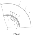
FIG. 3 is an explanatory diagram illustrating an example of a portion of the marine hose in a cross-sectional view taken along A-A ofFIG. 2 . -
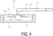
FIG. 4 is an explanatory diagram illustrating an example of a detector in a top view. -
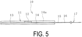
FIG. 5 is an explanatory diagram illustrating an example of the detector ofFIG. 4 in a side view. -
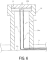
FIG. 6 is an explanatory diagram illustrating an example of a casing and the detector ofFIG. 2 in a longitudinal cross-sectional view. -
FIG. 7 is an explanatory diagram illustrating an example of the arrangement of a loop circuit in a top view with a portion of the marine hose removed. -
FIG. 8 is an explanatory diagram illustrating a modified example of the detector in a top view. -
FIG. 9 is an explanatory diagram illustrating an example of the arrangement of the loop circuit of the detector ofFIG. 8 in a top view with a portion of the marine hose removed. -
FIG. 10 is a B-B cross-sectional view ofFIG. 9 . -
FIG. 11 is an explanatory diagram illustrating a magnified portion of another marine hose with a detection system applied in a longitudinal cross-sectional view. - Hereinafter, a fluid leakage detection system (hereinafter referred to as a detection system) and method for a marine hose according to an embodiment of the present invention will be described with reference to the drawings.
- The detection system according to an embodiment illustrated in
FIG. 1 is applied to a floating typemarine hose 1 used in a state where it floats on the water surface and is configured to detect the presence or absence of leakage of a fluid L from a flow path 1a. Themarine hose 1 includes a cylindrical hose body andconnection fittings 2 connected to both ends of the hose body in a longitudinal direction. Theconnection fittings 2 each includes anipple 2b extending in the longitudinal direction of the hose body and aflange 2a joined to one end of thenipple 2b in the longitudinal direction. Themarine hoses 1 are connected to each other through theconnection fittings 2, and generally about tenmarine hoses 1 are connected and used. - As illustrated in
FIGS. 2 and3 , in the hose body between thenipples 2b at both ends of themarine hose 1 in the longitudinal direction, aninner surface layer 3, afirst reinforcing layer 4, abuoyant layer 8, and anouter surface layer 9 are layered in this order from the inner circumferential side to the outer circumferential side. Since the hose body does not include a fluid retention layer 7 described below, themarine hose 1 is a single carcass type. The inner circumferential side of theinner surface layer 3 serves as the flow path 1a of the fluid L. Examples of the fluid L include crude oil, heavy oil, gasoline, LPG, water, seawater, chemicals (alcohols refined from gasoline), and the like. - An appropriate material is selected for the
inner surface layer 3 in accordance with the type of the fluid L, and theinner surface layer 3 is formed of a material having excellent durability and corrosion resistance to the fluid L. In a case where the fluid L is crude oil, heavy oil, gasoline, or the like, theinner surface layer 3 is formed of nitrile rubber or the like having an excellent oil resistance. - The first reinforcing
layer 4 includes a plurality of layers of reinforcingcord layers 4A to 4H formed of multiple reinforcing cords arranged side by side and covered with rubber. In this embodiment, one reinforcing cord layer group of eight reinforcingcord layers 4A to 4H layered together corresponds to the first reinforcinglayer 4, but the number of layers of the reinforcingcord layers 4A to 4H is appropriately determined on the basis of the required performance of themarine hose 1. The first reinforcinglayer 4 is fixed to eachnipple 2b usingnipple wires 4w at both end portions and afixing ring 2c or the like disposed projecting out on the outer circumferential surface of eachnipple 2b. - The
buoyant layer 8 is formed of a material such as sponge rubber, polyurethane foam or the like that exhibits buoyancy to float themarine hose 1 above the sea. Theouter surface layer 9 is formed of a non-water-permeable material such as rubber, and has a line pattern or the like having excellent visibility on the surface thereof. - The detection system includes the
marine hose 1, adetector 10, acommunication unit 19, and acomputation device 20. Thecommunication unit 19 is separate from themarine hose 1 and is disposed on the outside of themarine hose 1. In this embodiment, thecommunication unit 19 and thecomputation device 20 are integrally formed, but a configuration can be used in which they are separate and independent. - As illustrated in
FIGS. 4 and5 , thedetector 10 includes apassive IC tag 11 and aloop circuit 17 connected to theIC tag 11. TheIC tag 11 is disposed on the surface of themarine hose 1 and positioned on the water. Theloop circuit 17 is formed by adetection element 15 and extends continuously in the longitudinal direction of the hose body between theinner surface layer 3 and thefirst reinforcing layer 4. - Specifically, the
IC tag 11 includes anIC chip 12 and anantenna unit 13 connected to theIC chip 12. TheIC chip 12 and theantenna unit 13 are disposed on asubstrate 14. TheIC chip 12 and theantenna unit 13 are covered with aninsulating layer 14a, and theentire IC tag 11 is electrically insulated from the outside. However, theIC tag 11 and thedetection element 15 are electrically conductively connected to each other. The insulatinglayer 14a is formed of a known insulating material such as insulating rubber, resins such as polyester, and natural fibers. - The
IC chip 12 arbitrarily stores tag unique information such as an identification number of theIC tag 11, element identification information for specifying thedetection element 15 connected to theIC tag 11, and other necessary information. Although various types of known antennas can be used as theantenna unit 13, a dipole antenna extending left-right symmetrically from theIC chip 12 is employed in this embodiment. Theantenna unit 13 is appropriately folded back so as to increase the extension length in a limited space. - The commonly distributed specifications are adopted for the
IC tag 11, and for example, an RFID tag can be used. TheIC chip 12 has a very small size, for example, a vertical dimension and a horizontal dimension of 50 mm or less (corresponding to an outer diameter of 50 mm or less) and a thickness of 5 mm or less. The size of theantenna unit 13 is also very small, for example, the vertical dimension and the horizontal dimension are each 50 mm or less (corresponding to an outer diameter of 50 mm or less) and the thickness is 10 mm or less. - The
detection element 15 is a linear member with electrical conductivity and is formed of conductive rubber or conductive paste (paste containing metal particles) whose electrical resistance value changes to a value equal to or greater than a preset reference by being impregnated with the fluid L flowing through the flow path 1a. If the difference in the electrical resistance value of thedetection element 15 depending on presence or absence of impregnation with the fluid L is too small, the sensitivity for detecting leakage of the fluid L is decreased. Thus, preferably, the difference in the electrical resistance value of thedetection element 15 is larger when thedetection element 15 is impregnated with the fluid L compared to when thedetection element 15 is not impregnated. Thus, the electrical resistance value per unit length in a unit cross-sectional area of thedetection element 15 when impregnated with the fluid L is set to, for example, twice or more, preferably three times or more, and more preferably five times or more of the reference electrical resistance value per unit length in a unit cross-sectional area of thedetection element 15 in a state in which it is not impregnated with the fluid L. The electrical resistance value in the case of impregnation with the fluid L is a value measured in a state in which the fluid L adheres to the entire outer circumferential surface of thedetection element 15 in a linear state. In order to make the electrical resistance value of thedetection element 15 equal to or greater than the preset reference value by impregnation with the fluid L as described above, for example, the content ratio between the conductive component and the insulating component of thedetection element 15 is adjusted. - When the
detection element 15 is bent in conjunction with localized bending of themarine hose 1, the electrical resistance value of thedetection element 15 is increased to some extent. Thus, it becomes unclear whether the change in the electrical resistance value of thedetection element 15 is caused by the impregnation of thedetection element 15 with the fluid L or the bending of thedetection element 15. Thus, preferably, the difference in the electrical resistance value in the case where thedetection element 15 is bent is smaller than the difference in the case where thedetection element 15 is not bent. Thus, the electrical resistance value per unit length in a unit cross-sectional area of thedetection element 15 in a bent state is set to, for example, 1.5 times or less, preferably 1.3 times or less, and more preferably 1.1 times or less of the reference electrical resistance value per unit length in a unit cross-sectional area of thedetection element 15 in a linear state. The electrical resistance value in a state in which thedetection element 15 is bent is a value measured in a state in which thedetection element 15 is bent by 90°. In order to make the electrical resistance value of thedetection element 15 in a bent state equal to or less than the preset reference value as described above, for example, the content ratio of the elasticity component of thedetection element 15 is adjusted. - The
detection element 15 has an outer diameter (width) ranging from, for example, 1 mm to 20 mm and preferably from 5 mm to 10 mm. Thedetection element 15 is preferably a simple wire having a circular cross-section but may be a flat linear member (band-like wire). - The outer circumferential surface of the
detection element 15 is covered with aninsulator 16, and thedetection element 15 is electrically insulated from the outside. Theinsulator 16 is formed of a known insulating material in a similar manner as the insulatinglayer 14a. However, theinsulator 16 is formed of a material through which the fluid L permeates or includes a through-hole so that the fluid L can pass through theinsulator 16 and reach thedetection element 15. - One end portion and the other end portion of the
detection element 15 in the longitudinal direction are electrically connected to theIC chip 12, forming theloop circuit 17 outside theIC tag 11. The interval between thedetection elements 15 extending in parallel in theloop circuit 17 is, for example, 5 mm or more and 50 mm or less. The IC tag 11 (the substrate 14) is provided with a large number of pairs of terminals connected to theIC chip 12. Each of one end portion and the other end portion of thedetection element 15 in the longitudinal direction is connected to the pair of terminals and thus is electrically connected to theIC chip 12. Thedetection element 15 and the pair of terminals are connected by using an eyelet and a crimp terminal or by using a conductive adhesive, welding, solder, or the like. In this embodiment, five pairs of terminals are provided; however, the number of pairs of terminals provided on the IC tag 11 (the substrate 14) is not particularly limited and may be one pair of terminals. Since a space is restricted, the number of pairs of terminals provided on one IC tag 11 (substrate 14) is, for example, about one to six pairs of terminals. - The
IC tag 11 is preferably disposed at a longitudinal end portion of themarine hose 1. The loop circuit 17 (detection element 15) preferably extends continuously from one end portion to the other end portion in the longitudinal direction of the hose body so as to cover the entire length of the hose body. In this embodiment, theIC tag 11 is disposed on the surface (outer circumferential surface of thenipple 2b) of the connection fitting 2 at one end portion of the hose body in the longitudinal direction. Specifically, as illustrated inFIG. 6 , theIC tag 11 is disposed inside acasing 18. Thecasing 18 includes a cylindrical base portion 18a and acover portion 18b attached to an upper end portion of the base portion 18a. - The base portion 18a is erected on the outer circumferential surface of the
nipple 2b covered with theouter surface layer 9. The base portion 18a is formed of, for example, stainless steel or a similar metal. Thecover portion 18b is screwed to the upper end portion of the base portion 18a to watertightly close the upper end opening, and theIC tag 11 is disposed in the watertightly closed internal space of thecasing 18. Thecover portion 18b is formed of a material that allows transmission radio waves R1 and return radio waves R2 to pass through, this material being, for example, polycarbonate, polyamide, epoxy resin, or the like. The casing 18 (cover portion 18b) may be orange so as to be noticeable in the ocean, for example. - The detection element 15 (loop circuit 17) extends from the inside of the
casing 18 toward the hose body, is disposed between theinner surface layer 3 and the first reinforcinglayer 4 in the hose body, and extends continuously from one end portion to the other end portion in the longitudinal direction of the hose body. In this embodiment, as illustrated inFIG. 7 , theloop circuit 17 is spirally wound around the hose body and extends from one end portion to the other end portion in the longitudinal direction of the hose body. That is, theloop circuit 17 is spirally wound around the outer circumferential surface of theinner surface layer 3. The spiral pitch of theloop circuit 17 is, for example, 20 cm or more and 50 cm or less. A dot-dash line CL in the diagram is an axial center passing through a cross-sectional center CL of the marine hose 1 (hose body). When theloop circuit 17 extends in a spiral shape as described above, there is an advantage that even oneloop circuit 17 can efficiently cover the entire range of the hose body. - The
communication unit 19 includes a radiowave transmission unit 19a and a radiowave reception unit 19b. The radiowave transmission unit 19a transmits the transmission radio waves R1 to theIC tag 11, and the radiowave reception unit 19b receives the return radio waves R2 transmitted from theIC tag 11. TheIC tag 11 is activated by the transmission radio waves R1, and the return radio waves R2 are transmitted from the activatedIC tag 11 in response to the transmission radio wave R2, whereby wireless communication is performed between theIC tag 11 and thecommunication unit 19. - The commonly distributed specifications that allow wireless communication with a passive RFID tag or the like are adopted for the
communication unit 19. Thus, theIC tag 11 and thecommunication unit 19 constitute a radio frequency identification (RFID) system. Since the passivetype IC tag 11 is used, the communication distance of the radio waves R1 and R2 between theIC tag 11 and thecommunication unit 19 is, for example, several tens of centimeters or more and several meters or less. - The frequency of radio waves (R1 and R2) used for wireless communication between the
IC tag 11 and thecommunication unit 19 is mainly in the UHF band (depending on the country, in a range of 860 MHz or more and 930 MHz or less, in a range of 915 MHz or more and 930 MHz or less in Japan), and the HF band (13.56 MHz) may be used. A monitor or the like may be attached to thecommunication unit 19, for example. - The
computation device 20 performs various computational processing using the input data. A known computer is used as thecomputation device 20, and reference resistance value data Dc is input to thecomputation device 20 in advance. The reference resistance value data Dc is an electrical resistance value at theloop circuit 17 when the IC tag is activated in a sound state of themarine hose 1 in which the fluid L is not leaking from the flow path 1a. The reference resistance value data Dc is obtained and determined by performing a preliminary test or the like. Data obtained by thecommunication unit 19 is also input to thecomputation device 20. An output unit such as a monitor is connected to thecomputation device 20. - Hereinafter, an example of a detection procedure for determining whether or not the fluid L is leaking from the flow path 1a by using this detection system will be described.
- For example, using a work boat or the like, a worker periodically or when necessary approaches the
marine hose 1 and performs work to confirm whether there is leakage of the fluid L and sets thecommunication unit 19 at a position where wireless communication with theIC tag 11 can be checked. Then, as illustrated inFIG. 2 , at the check position, the transmission radio waves R1 are transmitted from the radiowave transmission unit 19a toward theIC tag 11, and the transmission radio waves R1 are used to generate electric power to activate theIC tag 11. - Electric power is generated in the
IC tag 11 by the transmission radio waves R1 received by theantenna unit 13, and theIC tag 11 is activated. The activatedIC tag 11 transmits the return radio waves R2 by the electric power via theantenna unit 13, and the return radio waves R2 are received by the radiowave reception unit 19b. When theIC tag 11 is activated, a current flows through theloop circuit 17, and electrical resistance value data Dr of theloop circuit 17 is stored in theIC tag 11. The electrical resistance value data Dr is transmitted from theIC tag 11 to thecommunication unit 19 by the return radio waves R2. The electrical resistance value data Dr is received by the radiowave reception unit 19b and thereafter inputted to thecomputation device 20 as obtained data by thecommunication unit 19. - The
computation device 20 determines presence or absence of a leakage of the fluid L from the flow path 1a on the basis of the magnitude of the difference between the input electrical resistance value data Dr and the preset reference resistance value data Dc. When theinner surface layer 3 is sound and the fluid L is not leaking from theinner surface layer 3, the electrical resistance value data Dr of theloop circuit 17 and the reference resistance value data Dc are substantially the same and have almost no difference. - On the other hand, when the
inner surface layer 3 is broken and there is a leakage of the fluid L from the flow path 1a to the outside of theinner surface layer 3, the fluid L comes into contact with thedetection elements 15 forming theloop circuit 17, and the electrical resistance value of theloop circuit 17 rapidly and largely changes (becomes extremely large), putting it in an insulating state or a state close to an insulating state. That is, the electrical resistance value data Dr of theloop circuit 17 when theIC tag 11 is activated becomes significantly larger than the reference resistance value data Dc. - Then, the
computation device 20 compares the input electrical resistance value data Dr with the reference resistance value data Dc. As a result, when the electrical resistance value data Dr is greater than the reference resistance value data Dc and exceeds a tolerance range AR, it is determined that the fluid L is leaking from the flow path 1a. This result is then communicated via a monitor display or audio. When the difference between the electrical resistance value data Dr and the reference resistance value data Dc is within the tolerance range AR, it is determined that the fluid L is not leaking from the flow path 1a. This result is then communicated via a monitor display, for example. - In this manner, presence or absence of leakage of the fluid L can be accurately determined on the basis of the magnitude of the difference between the electrical resistance value data Dr received by the radio
wave reception unit 19b and the reference resistance value data Dc. The tolerance range AR may be appropriately set by performing a preliminary test or the like. According to this embodiment, it is possible to accurately detect a minute leak in which theinner surface layer 3 is cracked and the fluid L gradually leaks out through the outer circumferential surface of theinner surface layer 3. - The
computation device 20 can also be configured to connect to a terminal device such as a computer or a smartphone located at a position (remote location) away from the use site of themarine hose 1 via a communication network such as the Internet. According to this configuration, thecomputation device 20 can transmit the electrical resistance value data Dr and the determination result (presence or absence of leakage of the fluid L) by thecomputation device 20 to the terminal device located at a position away from the use site of themarine hose 1 through the communication network. For example, the electrical resistance value data Dr and the determination result by thecomputation device 20 are transmitted to a terminal device of a related person in management of an operating company (user) of themarine hose 1, a sales company of themarine hose 1, or a manufacturing company of themarine hose 1 at a remote location with respect to the use site of themarine hose 1. This allows the related person to obtain the state of themarine hose 1 while being at the remote location with respect to the use site of themarine hose 1. - The
detector 10 illustrated inFIG. 8 may be used. Thedetector 10 is configured such that a plurality of (four)detection elements IC tag 11. The outer circumferential surface of each of thedetection elements insulator 16. Thedetection elements independent loop circuits IC tag 11. - As illustrated in
FIGS. 9 and10 , in themarine hose 1 including thedetector 10, the independent loop circuits 17a to 17d are disposed at intervals in the circumferential direction with respect to the hose body and linearly extend in the longitudinal direction of the hose body. The loop circuits 17a to 17d are preferably disposed at regular intervals in a circumferential direction of the hose body. - Using this
detector 10 has an advantage that even if oneloop circuit 17 fails for some reason, the presence or absence of leakage of the fluid L can be detected by theother loop circuits 17. In addition, since the total length of each of the loop circuits 17a to 17d can be shortened, compared to a case where theloop circuit 17 extends in a spiral shape, there is an advantage in that a change in the electrical resistance value at each of the loop circuits 17a to 17d can be detected with more sensitivity (higher sensitivity). When thedetector 10 is used, the loop circuits 17a to 17d may be shifted in the longitudinal direction of the hose body and spirally wound around the hose body so as to extend. - The detection system described above can be applied not only to the
marine hose 1 of a single carcass type but also to themarine hose 1 of a double carcass type including the fluid retention layer 7 in the hose body. As illustrated inFIG. 11 , in the hose body of themarine hose 1, theinner surface layer 3, the first reinforcinglayer 4, abody wire layer 5, the fluid retention layer 7, a second reinforcing layer 6, thebuoyant layer 8, and theouter surface layer 9 are layered in this order from the inner circumferential side to the outer circumferential side. Themarine hose 1 is a double carcass type including the first reinforcinglayer 4 and the second reinforcing layer 6 layered with an interval therebetween in the radial direction of a hose body and the fluid retention layer 7 interposed therebetween. Note that thebody wire layer 5 can be discretionarily provided. - The first reinforcing
layer 4 and the second reinforcing layer 6 each include a plurality of layers of reinforcing cord layers formed of multiple reinforcing cords arranged side by side and covered with rubber. Thebody wire layer 5 is configured by spirally winding metal wires around the outer circumferential surface of the first reinforcinglayer 4 at predetermined intervals. The first reinforcinglayer 4, thebody wire layer 5, and the second reinforcing layer 6 are fixed to eachnipple 2b usingnipple wires ring 2c or the like disposed projecting out on the outer circumferential surface of eachnipple 2b at both end portions of the hose body. The fluid retention layer 7 formed between the first reinforcinglayer 4 and the second reinforcing layer 6 is a space for storing the fluid L that has leaked from the flow path 1a. - In the
marine hose 1, theloop circuit 17 is disposed inside the fluid retention layer 7. Thus, when the fluid L leaks due to damage to theinner surface layer 3, passes through thebody wire layer 5, and enters the fluid retention layer 7, the fluid L comes into contact with thedetection elements 15 forming theloop circuit 17, and the electrical resistance value of theloop circuit 17 rapidly and largely changes (becomes extremely large), putting it in an insulating state or a state close to an insulating state. That is, the electrical resistance value data Dr of theloop circuit 17 when theIC tag 11 is activated becomes significantly larger than the reference resistance value data Dc. When theinner surface layer 3 is sound and the fluid L is not leaking from theinner surface layer 3, the electrical resistance value data Dr of theloop circuit 17 and the reference resistance value data Dc have almost no difference. In this manner, as described above, presence or absence of leakage of the fluid L can be accurately determined on the basis of the magnitude of the difference between the electrical resistance value data Dr received by the radiowave reception unit 19b and the reference resistance value data Dc. - When the fluid L flows into a part of the fluid retention layer 7, the fluid L gradually spreads over the entire length of the fluid retention layer 7. Thus, when the
loop circuit 17 is disposed inside the fluid retention layer 7, theloop circuit 17 does not need to be extended so long. Thus, theloop circuit 17 is continuously extended from one end in the longitudinal direction of the hose body to a position of, for example, 20% or more and 50% or less of the entire length of the hose body. - As with the
marine hose 1 illustrated inFIG. 2 , thismarine hose 1 may have a configuration in which theloop circuit 17 is disposed on the outer circumferential surface of theinner surface layer 3. When theloop circuit 17 is disposed on the outer circumferential surface of theinner surface layer 3, it preferably extends continuously from one end portion to the other end portion in the longitudinal direction of the hose body. Also in themarine hose 1, as illustrated inFIG. 7 , theloop circuit 17 may be spirally wound around the hose body and extended or, as illustrated inFIGS. 9 and10 , the plurality ofloop circuits 17 may be disposed at intervals in the circumferential direction of the hose body and linearly extend in the longitudinal direction of the hose body. - As described above, the detection system is highly versatile because it can be applied to both single carcass type and double carcass type
marine hoses 1. Further, since the electrical resistance value data Dr can be obtained via wireless communication using the return radio waves R2 transmitted from theIC tag 11 to thecommunication unit 19 in response to the transmission radio waves R1 from thecommunication unit 19, it greatly contributes to reduction in labor for checking the fluid leakage. Since thepassive IC tag 11 is used, the work of monitoring the status of the battery life of theIC tag 11 also becomes unnecessary. -
- 1 Marine hose
- 1a Flow path
- 2 Connection fitting
- 2a Flange
- 2b Nipple
- 2c Fixing ring
- 3 Inner surface layer
- 4 First reinforcing layer
- 4A to 4H Reinforcing cord layer
- 4w Nipple wire
- 5 Body wire layer
- 5w Nipple wire
- 6 Second reinforcing layer
- 6w Nipple wire
- 7 Fluid retention layer
- 8 Buoyant layer
- 9 Outer surface layer
- 10 Detector
- 11 IC tag
- 12 IC chip
- 13 Antenna unit
- 14 Substrate
- 14a Insulating layer
- 15 (15a, 15b, 15c, 15d) Detection element
- 16 Insulator
- 17 (17a, 17b, 17c, 17d) Loop circuit
- 18 Casing
- 18a Base portion
- 18b Cover portion
- 19 Communication unit
- 19a Radio wave transmission unit
- 19b Radio wave reception unit
- 20 Computation device
Claims (6)
- A fluid leakage detection system for a marine hose provided with a hose body including a reinforcing layer and a buoyant layer layered in this order from an inner circumferential side between an inner surface layer and an outer surface layer and connection fittings connected to both respective ends of the hose body in a longitudinal direction, the inner surface layer including an inner circumferential region as a flow path, the fluid leakage detection system comprising:the marine hose;a detector including an IC tag that is passive and a loop circuit formed of a detection element connected to the IC tag;a communication unit disposed outside the marine hose and configured to wirelessly communicate with the IC tag; anda computation device into which obtained data from the communication unit is input;the IC tag being disposed on a surface of the marine hose,the detection element being formed of conductive rubber or conductive paste whose electrical resistance value changes to a value equal to or greater than a preset reference by being impregnated with fluid flowing through the flow path, the detection element continuously extending in the longitudinal direction of the hose body between the inner surface layer and the reinforcing layer,the IC tag being activated by transmission radio waves transmitted from the communication unit, return radio waves being transmitted from the IC tag activated in response to the transmission radio waves, and thus wireless communication between the IC tag and the communication unit being performed, andelectrical resistance value data at the loop circuit when the IC tag is activated being transmitted from the IC tag to the communication unit via the return radio waves and being input into the computation device as the obtained data, and presence or absence of leakage of the fluid from the flow path being determined by the computation device in accordance with a magnitude of a difference between the obtained data input and preset reference resistance value data.
- The fluid leakage detection system for a marine hose according to claim 1, wherein the loop circuit is spirally wound and extends around the hose body.
- The fluid leakage detection system for a marine hose according to claim 1, comprisinga plurality of the loop circuits, whereineach of the loop circuits is disposed at intervals in a circumferential direction of the hose body and linearly extends in the longitudinal direction of the hose body.
- The fluid leakage detection system for a marine hose according to any one of claims 1 to 3, whereinthe marine hose is a single carcass type including only one reinforcing cord layer group as the reinforcing layer, andthe loop circuit is disposed on an outer circumferential surface of the inner surface layer.
- The fluid leakage detection system for a marine hose according to any one of claims 1 to 3, whereinthe marine hose is a double carcass type including two of the reinforcing layers layered at intervals in a radial direction of the hose body with a fluid retention layer interposed therebetween, andthe loop circuit is disposed on an outer circumferential surface of the inner surface layer or in the fluid retention layer.
- A fluid leakage detection method for a marine hose provided with a hose body including a reinforcing layer and a buoyant layer layered in this order from an inner circumferential side between an inner surface layer and an outer surface layer and connection fittings connected to both respective ends of the hose body in a longitudinal direction, the inner surface layer including an inner circumferential region as a flow path, the fluid leakage detection method comprising:using a detector including an IC tag that is passive and a loop circuit formed of a detection element connected to the IC tag, a communication unit disposed outside the marine hose and configured to wirelessly communicate with the IC tag, and a computation device into which obtained data from the communication unit is input;disposing the IC tag on a surface of the marine hose, forming the detection element of conductive rubber or conductive paste whose electrical resistance value changes to a value equal to or greater than a preset reference by being impregnated with fluid flowing through the flow path, and continuously extending the detection element in the longitudinal direction of the hose body between the inner surface layer and the reinforcing layer;activating the IC tag with transmission radio waves transmitted from the communication unit, transmitting return radio waves from the IC tag to the communication unit in response to the transmission radio waves, thus performing wireless communication between the IC tag and the communication unit, transmitting electrical resistance value data at the loop circuit when the IC tag is activated from the IC tag to the communication unit via the return radio waves, and inputting the electrical resistance value data as the obtained data into the computation device; anddetermining, by the computation device, presence or absence of leakage of the fluid from the flow path in accordance with a magnitude of a difference between the obtained data input and preset reference resistance value data.
Applications Claiming Priority (2)
| Application Number | Priority Date | Filing Date | Title |
|---|---|---|---|
| JP2022100069A JP2024001434A (en) | 2022-06-22 | 2022-06-22 | Fluid leakage detection system and method for marine hose |
| PCT/JP2022/046526 WO2023248500A1 (en) | 2022-06-22 | 2022-12-16 | Fluid leakage detection system and method for marine hose |
Publications (1)
| Publication Number | Publication Date |
|---|---|
| EP4545837A1 true EP4545837A1 (en) | 2025-04-30 |
Family
ID=89379382
Family Applications (1)
| Application Number | Title | Priority Date | Filing Date |
|---|---|---|---|
| EP22948059.5A Pending EP4545837A1 (en) | 2022-06-22 | 2022-12-16 | Fluid leakage detection system and method for marine hose |
Country Status (4)
| Country | Link |
|---|---|
| EP (1) | EP4545837A1 (en) |
| JP (1) | JP2024001434A (en) |
| CN (1) | CN119343557A (en) |
| WO (1) | WO2023248500A1 (en) |
Families Citing this family (1)
| Publication number | Priority date | Publication date | Assignee | Title |
|---|---|---|---|---|
| CN119624331B (en) * | 2025-02-14 | 2025-04-25 | 苏州银橡智能科技有限公司 | A hazardous chemicals storage management system and method based on artificial intelligence |
Family Cites Families (5)
| Publication number | Priority date | Publication date | Assignee | Title |
|---|---|---|---|---|
| US7387012B2 (en) * | 2006-07-14 | 2008-06-17 | Veyance Technologies, Inc. | Leak detection sensor system and method for double carcass hose |
| JP5013252B2 (en) * | 2007-06-22 | 2012-08-29 | 横浜ゴム株式会社 | Marine hose |
| US8515687B2 (en) * | 2009-01-06 | 2013-08-20 | Eaton Corporation | Degradation detection system for a hose assembly |
| JP7389313B2 (en) * | 2018-12-18 | 2023-11-30 | 横浜ゴム株式会社 | Marine hose fluid leak detection system |
| JP7243270B2 (en) | 2019-02-20 | 2023-03-22 | 横浜ゴム株式会社 | Marine hose fluid leak detection system |
-
2022
- 2022-06-22 JP JP2022100069A patent/JP2024001434A/en active Pending
- 2022-12-16 EP EP22948059.5A patent/EP4545837A1/en active Pending
- 2022-12-16 WO PCT/JP2022/046526 patent/WO2023248500A1/en not_active Ceased
- 2022-12-16 CN CN202280096964.3A patent/CN119343557A/en active Pending
Also Published As
| Publication number | Publication date |
|---|---|
| CN119343557A (en) | 2025-01-21 |
| WO2023248500A1 (en) | 2023-12-28 |
| JP2024001434A (en) | 2024-01-10 |
Similar Documents
| Publication | Publication Date | Title |
|---|---|---|
| CN111594768B (en) | Fluid leakage sensing system for marine hose | |
| JP7389327B2 (en) | Marine hose fluid leak detection system | |
| KR101969575B1 (en) | Leak liquid sensing device | |
| KR101901715B1 (en) | Antenna module and electronic device having the same | |
| EP3412951A1 (en) | Marine hose status monitoring system | |
| WO2023248500A1 (en) | Fluid leakage detection system and method for marine hose | |
| US10950379B2 (en) | Transmission coil and power transmission apparatus | |
| EP4545842A1 (en) | Marine hose monitoring system and method | |
| US6070617A (en) | Liquid-transferring hose | |
| US12060953B2 (en) | Composite hose with radio frequency identification (RFID) enabled sensor | |
| EP3901503A1 (en) | Fluid leakage detection system for marine hose | |
| JP2001016025A (en) | Antenna for trnsponder, transponder, and transponder unit | |
| KR102087562B1 (en) | Leakage liquid senser device and leakage liquid sensing system | |
| KR20170101407A (en) | Hose having function of leak detection and manufacturing method thereof | |
| EP4428431A1 (en) | Marine hose fluid leakage detection system and method for manufacturing same | |
| WO2017110788A1 (en) | Wire harness | |
| KR101983195B1 (en) | Antenna module and electronic device having the same | |
| WO2024252699A1 (en) | Drone comprising communication antenna, and monitoring system and monitoring method using said drone | |
| CN222687516U (en) | A marine high-pressure oil hose | |
| RU2754599C2 (en) | Sensor for identification of structures located at large depth | |
| NL1015354C2 (en) | Composite gas or oil pipeline with embedded microchip and electrodes to detect corrosion and send data by radio signal to remote processor | |
| US11073411B2 (en) | Pressure pass-through apparatus, and method for making such | |
| JP5254528B2 (en) | Gas hose |
Legal Events
| Date | Code | Title | Description |
|---|---|---|---|
| STAA | Information on the status of an ep patent application or granted ep patent |
Free format text: STATUS: THE INTERNATIONAL PUBLICATION HAS BEEN MADE |
|
| PUAI | Public reference made under article 153(3) epc to a published international application that has entered the european phase |
Free format text: ORIGINAL CODE: 0009012 |
|
| STAA | Information on the status of an ep patent application or granted ep patent |
Free format text: STATUS: REQUEST FOR EXAMINATION WAS MADE |
|
| 17P | Request for examination filed |
Effective date: 20241031 |
|
| AK | Designated contracting states |
Kind code of ref document: A1 Designated state(s): AL AT BE BG CH CY CZ DE DK EE ES FI FR GB GR HR HU IE IS IT LI LT LU LV MC ME MK MT NL NO PL PT RO RS SE SI SK SM TR |
|
| DAV | Request for validation of the european patent (deleted) | ||
| DAX | Request for extension of the european patent (deleted) |