EP4545807A1 - Actuator assembly - Google Patents
Actuator assembly Download PDFInfo
- Publication number
- EP4545807A1 EP4545807A1 EP23306857.6A EP23306857A EP4545807A1 EP 4545807 A1 EP4545807 A1 EP 4545807A1 EP 23306857 A EP23306857 A EP 23306857A EP 4545807 A1 EP4545807 A1 EP 4545807A1
- Authority
- EP
- European Patent Office
- Prior art keywords
- assembly
- rod
- actuator
- tie rods
- control block
- Prior art date
- Legal status (The legal status is an assumption and is not a legal conclusion. Google has not performed a legal analysis and makes no representation as to the accuracy of the status listed.)
- Pending
Links
Images


Classifications
-
- F—MECHANICAL ENGINEERING; LIGHTING; HEATING; WEAPONS; BLASTING
- F15—FLUID-PRESSURE ACTUATORS; HYDRAULICS OR PNEUMATICS IN GENERAL
- F15B—SYSTEMS ACTING BY MEANS OF FLUIDS IN GENERAL; FLUID-PRESSURE ACTUATORS, e.g. SERVOMOTORS; DETAILS OF FLUID-PRESSURE SYSTEMS, NOT OTHERWISE PROVIDED FOR
- F15B15/00—Fluid-actuated devices for displacing a member from one position to another; Gearing associated therewith
- F15B15/08—Characterised by the construction of the motor unit
- F15B15/14—Characterised by the construction of the motor unit of the straight-cylinder type
- F15B15/1423—Component parts; Constructional details
- F15B15/1428—Cylinders
-
- F—MECHANICAL ENGINEERING; LIGHTING; HEATING; WEAPONS; BLASTING
- F15—FLUID-PRESSURE ACTUATORS; HYDRAULICS OR PNEUMATICS IN GENERAL
- F15B—SYSTEMS ACTING BY MEANS OF FLUIDS IN GENERAL; FLUID-PRESSURE ACTUATORS, e.g. SERVOMOTORS; DETAILS OF FLUID-PRESSURE SYSTEMS, NOT OTHERWISE PROVIDED FOR
- F15B15/00—Fluid-actuated devices for displacing a member from one position to another; Gearing associated therewith
- F15B15/08—Characterised by the construction of the motor unit
- F15B15/14—Characterised by the construction of the motor unit of the straight-cylinder type
-
- F—MECHANICAL ENGINEERING; LIGHTING; HEATING; WEAPONS; BLASTING
- F15—FLUID-PRESSURE ACTUATORS; HYDRAULICS OR PNEUMATICS IN GENERAL
- F15B—SYSTEMS ACTING BY MEANS OF FLUIDS IN GENERAL; FLUID-PRESSURE ACTUATORS, e.g. SERVOMOTORS; DETAILS OF FLUID-PRESSURE SYSTEMS, NOT OTHERWISE PROVIDED FOR
- F15B15/00—Fluid-actuated devices for displacing a member from one position to another; Gearing associated therewith
- F15B15/08—Characterised by the construction of the motor unit
- F15B15/14—Characterised by the construction of the motor unit of the straight-cylinder type
- F15B15/1423—Component parts; Constructional details
- F15B15/1433—End caps
-
- F—MECHANICAL ENGINEERING; LIGHTING; HEATING; WEAPONS; BLASTING
- F15—FLUID-PRESSURE ACTUATORS; HYDRAULICS OR PNEUMATICS IN GENERAL
- F15B—SYSTEMS ACTING BY MEANS OF FLUIDS IN GENERAL; FLUID-PRESSURE ACTUATORS, e.g. SERVOMOTORS; DETAILS OF FLUID-PRESSURE SYSTEMS, NOT OTHERWISE PROVIDED FOR
- F15B15/00—Fluid-actuated devices for displacing a member from one position to another; Gearing associated therewith
- F15B15/08—Characterised by the construction of the motor unit
- F15B15/14—Characterised by the construction of the motor unit of the straight-cylinder type
- F15B15/1423—Component parts; Constructional details
- F15B15/1438—Cylinder to end cap assemblies
-
- F—MECHANICAL ENGINEERING; LIGHTING; HEATING; WEAPONS; BLASTING
- F15—FLUID-PRESSURE ACTUATORS; HYDRAULICS OR PNEUMATICS IN GENERAL
- F15B—SYSTEMS ACTING BY MEANS OF FLUIDS IN GENERAL; FLUID-PRESSURE ACTUATORS, e.g. SERVOMOTORS; DETAILS OF FLUID-PRESSURE SYSTEMS, NOT OTHERWISE PROVIDED FOR
- F15B15/00—Fluid-actuated devices for displacing a member from one position to another; Gearing associated therewith
- F15B15/20—Other details, e.g. assembly with regulating devices
- F15B15/202—Externally-operated valves mounted in or on the actuator
-
- F—MECHANICAL ENGINEERING; LIGHTING; HEATING; WEAPONS; BLASTING
- F15—FLUID-PRESSURE ACTUATORS; HYDRAULICS OR PNEUMATICS IN GENERAL
- F15B—SYSTEMS ACTING BY MEANS OF FLUIDS IN GENERAL; FLUID-PRESSURE ACTUATORS, e.g. SERVOMOTORS; DETAILS OF FLUID-PRESSURE SYSTEMS, NOT OTHERWISE PROVIDED FOR
- F15B2211/00—Circuits for servomotor systems
- F15B2211/70—Output members, e.g. hydraulic motors or cylinders or control therefor
- F15B2211/705—Output members, e.g. hydraulic motors or cylinders or control therefor characterised by the type of output members or actuators
- F15B2211/7051—Linear output members
- F15B2211/7053—Double-acting output members
- F15B2211/7054—Having equal piston areas
-
- F—MECHANICAL ENGINEERING; LIGHTING; HEATING; WEAPONS; BLASTING
- F15—FLUID-PRESSURE ACTUATORS; HYDRAULICS OR PNEUMATICS IN GENERAL
- F15B—SYSTEMS ACTING BY MEANS OF FLUIDS IN GENERAL; FLUID-PRESSURE ACTUATORS, e.g. SERVOMOTORS; DETAILS OF FLUID-PRESSURE SYSTEMS, NOT OTHERWISE PROVIDED FOR
- F15B2215/00—Fluid-actuated devices for displacing a member from one position to another
- F15B2215/30—Constructional details thereof
- F15B2215/305—Constructional details thereof characterised by the use of special materials
Definitions
- the present disclosure is concerned with actuators having a movable rod and a control block, e.g. hydraulic actuators having a ram rod and a hydraulic block for causing movement of the rod.
- Actuators are used in a wide variety of fields and applications for moving parts or surfaces from one position to another. Actuators are commonly used, for example, in aircraft, for moving flight control surfaces or aircraft parts, doors etc. Many types of actuator are known, including mechanical, hydraulic and electrical actuators and combinations thereof e.g. electro-hydrostatic actuators, EHAs.
- An actuator typically has an actuator housing, or cylinder, also known as a ram body, within which an actuator ram or rod is located for axial movement relative to the housing. The rod is moved by application of power to one end of the rod. The other end of the rod is connected to a surface or part to be moved. Power is applied to the rod according to the type of actuator. In some actuators (hydraulic, EHA, etc) the rod is moved by the application of hydraulic fluid provided from a hydraulic assembly in a hydraulic block. The hydraulic block is assembled to the actuator housing.
- the actuator rod and ram body are typically subjected to high levels of mechanical stress, they typically need to be made of a strong material capable of withstanding such stresses, especially tensile stresses, such as steel.
- a strong material capable of withstanding such stresses, especially tensile stresses, such as steel.
- such materials are relatively expensive and heavy and it is usually desirable to reduce the overall weight and cost of an actuator assembly.
- the weight of aircraft parts should be minimised where possible, for reasons of efficiency.
- the control block e.g. the hydraulic block
- aluminium or, for higher pressure applications, titanium aluminium or, for higher pressure applications, titanium. Aluminium is not suitable for withstanding the high mechanical tensile stresses applied to the rod, and so cannot be used for that part.
- the actuator assembly therefore, typically is formed as two separate main structural parts, made of different materials, that are then assembled together.
- an actuator assembly comprising: an actuator cylinder, and an actuator control block, wherein the actuator cylinder and the control block are formed integrally of a first material, e.g. aluminium; the assembly further comprising two or more tie rods spanning a part of the cylinder, a front plate and a tailstock, the two or more tie rods, front plate and tailstock being formed of a second material, e.g. steel, able to withstand more tensile stress than the first material.
- a first material e.g. aluminium
- a method of making an actuator assembly is also provided.
- the actuator comprises an actuator housing or cylinder, also known as a ram body 1 mounted to a control block 10 - here a hydraulic block.
- a ram or piston rod 2 is slidably located within the cylinder 1, and moves relative to the cylinder responsive to the application of hydraulic fluid from the block.
- the rod 2 slides on bearings 3, 4 which support the rod relative to the cylinder but allow the relative axial movement.
- Seals 6, 6' are also provided to prevent the leakage of hydraulic fluid from the assembly.
- the sealing between the piston head and the ram body, providing sealing between the two chambers, is ensured by a special surface treatment or finish on the ram body main bore, coupled with an adapted sealing system fitted on the piston head.
- the cylinder needs to be made of a strong material that can withstand such stresses, e.g. steel.
- the control block 10 which is only subjected to hydraulic stress, is made of a lighter material such as aluminium or titanium. This results in a relatively complex and expensive two-part assembly that still has a heavy actuator rod.
- the cylinder is integrated into the control block 100 and is made of the same material as the control block e.g. aluminium.
- tie rods 30 are provided to link or connect the two attachment points of the power line through the tailstock 25, the body 100 and the front plate 35.
- the two or more tie rods are made of a stronger material that can withstand the tensile stresses, e.g. steel.
- the tie rods are tightened using an adapted nut assembly.
- the main part of the body can be made of e.g.
- tie rods aluminium, like the block 100, and strength is provided by the two or more tie rods.
- four tie rods 30 are provided linking/connecting the tailstock 25, the body 100 and the front plate 35.
- a sleeve 40 can be included in the assembly. If needed, this part is made of a different material to that of the hydraulic block, and has a special finish or surface treatment.
- parts of the assembly that are particularly subjected to stresses, especially tensile stresses e.g. the rear part (or tailstock) 25 are made of the stronger material and/or front plates 35 at the other end of the cylinder are also made of the stronger material.
- bearings 13, 14 are provided between the rod and the cylinder.
- the sleeve 40 may be provided between the rod and the cylinder to guide and seal against leakages. Other forms of seal may also be used.
- the traction load path through the assembly is distributed between the rod through the front bearing 14 through the front plates 35, through the tie rods assembly 30 and, through the steel tailstock 25.
- the ram body/cylinder By merging the ram body/cylinder with the control block e.g. hydraulic block, forming them of the same, lighter material e.g. aluminium, cost and weight is minimised.
- the required strength of the rod is provided by means of the tie rods made of a stronger material, e.g. steel.
- the ram body and the control block are integrated, they are supplied as a single component, which simplifies assembly and supply chain.
Landscapes
- Engineering & Computer Science (AREA)
- Physics & Mathematics (AREA)
- Fluid Mechanics (AREA)
- Mechanical Engineering (AREA)
- General Engineering & Computer Science (AREA)
- Actuator (AREA)
- Braking Arrangements (AREA)
Abstract
An actuator assembly comprising: an actuator control block (100), wherein the control block (100) is formed of a first material; the assembly further comprising two or more tie rods (30), a tailstock (25) and a front plate (35), the two or more tie rods, the tailstock (25) and the front plate (35) being formed of a second material able to withstand more tensile stress than the first material.
Description
- The present disclosure is concerned with actuators having a movable rod and a control block, e.g. hydraulic actuators having a ram rod and a hydraulic block for causing movement of the rod.
- Actuators are used in a wide variety of fields and applications for moving parts or surfaces from one position to another. Actuators are commonly used, for example, in aircraft, for moving flight control surfaces or aircraft parts, doors etc. Many types of actuator are known, including mechanical, hydraulic and electrical actuators and combinations thereof e.g. electro-hydrostatic actuators, EHAs. An actuator typically has an actuator housing, or cylinder, also known as a ram body, within which an actuator ram or rod is located for axial movement relative to the housing. The rod is moved by application of power to one end of the rod. The other end of the rod is connected to a surface or part to be moved. Power is applied to the rod according to the type of actuator. In some actuators (hydraulic, EHA, etc) the rod is moved by the application of hydraulic fluid provided from a hydraulic assembly in a hydraulic block. The hydraulic block is assembled to the actuator housing.
- Because the actuator rod and ram body are typically subjected to high levels of mechanical stress, they typically need to be made of a strong material capable of withstanding such stresses, especially tensile stresses, such as steel. On the other hand, such materials are relatively expensive and heavy and it is usually desirable to reduce the overall weight and cost of an actuator assembly. In aircraft, in particular, the weight of aircraft parts should be minimised where possible, for reasons of efficiency. To reduce the overall weight and cost of the actuator assembly, therefore, whilst maintaining the strength of the rod, it is common to fabricate the control block e.g. the hydraulic block, of a lighter material such as aluminium or, for higher pressure applications, titanium. Aluminium is not suitable for withstanding the high mechanical tensile stresses applied to the rod, and so cannot be used for that part. The actuator assembly, therefore, typically is formed as two separate main structural parts, made of different materials, that are then assembled together.
- Such assemblies, however, are still relatively heavy, expensive and complex, and require relatively time-consuming assembly. There is, therefore, a desire for simpler, less expensive, lighter actuator assemblies.
- According to the disclosure, there is provided an actuator assembly comprising: an actuator cylinder, and an actuator control block, wherein the actuator cylinder and the control block are formed integrally of a first material, e.g. aluminium; the assembly further comprising two or more tie rods spanning a part of the cylinder, a front plate and a tailstock, the two or more tie rods, front plate and tailstock being formed of a second material, e.g. steel, able to withstand more tensile stress than the first material.
- A method of making an actuator assembly is also provided.
- Examples of an actuator assembly according to this disclosure will now be described with reference to the drawings. It should be noted, that variations are possible within the scope of the claims.
-
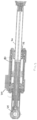
Figure 1 shows a typical actuator assembly architecture. -
Figure 2 shows a cross-section of a typical power line assembly such as shown inFig. 1 . -
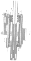
Figure 3 shows a cross-section of a power line assembly according to this disclosure. -
Figure 4 shows a detail of a power line assembly such as shown inFigure 3 . - The conventional actuator architecture shown in
Figs. 1 and2 will be briefly described by way of background. The assembly will not be described in detail, since such actuators are well-known. - The actuator comprises an actuator housing or cylinder, also known as a ram body 1 mounted to a control block 10 - here a hydraulic block. A ram or piston rod 2 is slidably located within the cylinder 1, and moves relative to the cylinder responsive to the application of hydraulic fluid from the block. The rod 2 slides on
bearings Seals 6, 6' are also provided to prevent the leakage of hydraulic fluid from the assembly. The sealing between the piston head and the ram body, providing sealing between the two chambers, is ensured by a special surface treatment or finish on the ram body main bore, coupled with an adapted sealing system fitted on the piston head. - As mentioned above, due to the high mechanical stresses to which it is subjected, especially traction, the cylinder needs to be made of a strong material that can withstand such stresses, e.g. steel. To minimise overall weight and cost, however, the
control block 10, which is only subjected to hydraulic stress, is made of a lighter material such as aluminium or titanium. This results in a relatively complex and expensive two-part assembly that still has a heavy actuator rod. - In the assembly according to the disclosure, examples of which will be described with reference to
Figs. 3 and4 , the cylinder is integrated into thecontrol block 100 and is made of the same material as the control block e.g. aluminium. - Of course, this does mean that the strength of the cylinder is reduced relative to the known assemblies and so the assembly requires modification to add the strength required to withstand the tensile stresses to which the power line assembly is subjected. To achieve the required strength, two or
more tie rods 30 are provided to link or connect the two attachment points of the power line through thetailstock 25, thebody 100 and thefront plate 35. The two or more tie rods are made of a stronger material that can withstand the tensile stresses, e.g. steel. The tie rods are tightened using an adapted nut assembly. Thus, rather than the entire body of the cylinder needing to be made of e.g. steel, the main part of the body can be made of e.g. aluminium, like theblock 100, and strength is provided by the two or more tie rods. In the example shown, fourtie rods 30 are provided linking/connecting thetailstock 25, thebody 100 and thefront plate 35. If needed to ensure sealing between the two chambers, a sleeve 40 can be included in the assembly. If needed, this part is made of a different material to that of the hydraulic block, and has a special finish or surface treatment. - In the preferred arrangement, parts of the assembly that are particularly subjected to stresses, especially tensile stresses, e.g. the rear part (or tailstock) 25 are made of the stronger material and/or
front plates 35 at the other end of the cylinder are also made of the stronger material. - As with the known assembly,
bearings - The traction load path through the assembly is distributed between the rod through the
front bearing 14 through thefront plates 35, through thetie rods assembly 30 and, through thesteel tailstock 25. - By merging the ram body/cylinder with the control block e.g. hydraulic block, forming them of the same, lighter material e.g. aluminium, cost and weight is minimised. The required strength of the rod is provided by means of the tie rods made of a stronger material, e.g. steel. As the ram body and the control block are integrated, they are supplied as a single component, which simplifies assembly and supply chain.
Claims (8)
- An actuator assembly comprising:
an actuator control block (100), wherein the control block (100) is formed of a first material; the assembly further comprising two or more tie rods (30), a tailstock (25) and a front plate (35), the two or more tie rods, the tailstock (25) and the front plate (35) being formed of a second material able to withstand more tensile stress than the first material. - The assembly of claim 1, further comprising nuts to tighten the tie rods.
- The assembly of any preceding claim, further comprising bearings (13, 14) between the rod and a rod housing within which the rod moves.
- The assembly of any preceding claim, wherein the first material is aluminium.
- The assembly of any preceding claim, wherein the second material is steel.
- The assembly of any preceding claim, further comprising a sleeve (40) between the rod and a rod housing within which the rod moves.
- A method of making an actuator assembly comprising integrally forming an actuator control block of a first material; and providing two or more tie rods, a tailstock and a front plate, of a second material capable of withstanding higher tensile stresses than the first material;
- The method of claim 7, further comprising tightening the tie rods by a nut assembly.
Priority Applications (3)
| Application Number | Priority Date | Filing Date | Title |
|---|---|---|---|
| EP23306857.6A EP4545807A1 (en) | 2023-10-23 | 2023-10-23 | Actuator assembly |
| CA3253340A CA3253340A1 (en) | 2023-10-23 | 2024-08-26 | Actuator assembly |
| US18/915,684 US20250129806A1 (en) | 2023-10-23 | 2024-10-15 | Actuator assembly |
Applications Claiming Priority (1)
| Application Number | Priority Date | Filing Date | Title |
|---|---|---|---|
| EP23306857.6A EP4545807A1 (en) | 2023-10-23 | 2023-10-23 | Actuator assembly |
Publications (1)
| Publication Number | Publication Date |
|---|---|
| EP4545807A1 true EP4545807A1 (en) | 2025-04-30 |
Family
ID=88697701
Family Applications (1)
| Application Number | Title | Priority Date | Filing Date |
|---|---|---|---|
| EP23306857.6A Pending EP4545807A1 (en) | 2023-10-23 | 2023-10-23 | Actuator assembly |
Country Status (3)
| Country | Link |
|---|---|
| US (1) | US20250129806A1 (en) |
| EP (1) | EP4545807A1 (en) |
| CA (1) | CA3253340A1 (en) |
Citations (3)
| Publication number | Priority date | Publication date | Assignee | Title |
|---|---|---|---|---|
| FR2229879A1 (en) * | 1973-05-15 | 1974-12-13 | Agiman Jacques | Electrically controlled double acting hydraulic ram - has oil-hydraulic accumulator charged when at rest |
| EP0701065A2 (en) * | 1994-08-27 | 1996-03-13 | Lingk & Sturzebecher GmbH | Pressure actuator for high pressure hydraulics |
| EP0987446A1 (en) * | 1998-09-15 | 2000-03-22 | Lingk & Sturzebecher Leichtbau GmbH | Hydraulic cylinder |
Family Cites Families (10)
| Publication number | Priority date | Publication date | Assignee | Title |
|---|---|---|---|---|
| US3165981A (en) * | 1961-02-13 | 1965-01-19 | Amour Alessandro | Fluid actuated servo-control device |
| US3158068A (en) * | 1961-12-28 | 1964-11-24 | Conair | Hydraulic actuator and control unit |
| US4909130A (en) * | 1986-04-28 | 1990-03-20 | Peninsular, Inc. | Cylinder end cap |
| US4977760A (en) * | 1987-12-15 | 1990-12-18 | Kubota, Ltd. | Speed control system for a working vehicle |
| DE20110965U1 (en) * | 2001-07-03 | 2001-09-06 | FESTO AG & Co., 73734 Esslingen | Working cylinder |
| DE102009014813B4 (en) * | 2009-03-25 | 2014-10-23 | Festo Ag & Co. Kg | linear actuator |
| JP6718584B2 (en) * | 2018-01-26 | 2020-07-08 | Smc株式会社 | Fluid pressure cylinder |
| US10836474B2 (en) * | 2018-07-03 | 2020-11-17 | The Boeing Company | Aircraft landing gear steering systems and methods with enhanced shimmy protection |
| US11300116B2 (en) * | 2018-08-27 | 2022-04-12 | Regents Of The University Of Minnesota | Long-stroke rolling diaphragm cylinder and methods of making same |
| GB2587317A (en) * | 2019-07-09 | 2021-03-31 | David Screation Lee | Lightweight hydraulic cylinder |
-
2023
- 2023-10-23 EP EP23306857.6A patent/EP4545807A1/en active Pending
-
2024
- 2024-08-26 CA CA3253340A patent/CA3253340A1/en active Pending
- 2024-10-15 US US18/915,684 patent/US20250129806A1/en active Pending
Patent Citations (3)
| Publication number | Priority date | Publication date | Assignee | Title |
|---|---|---|---|---|
| FR2229879A1 (en) * | 1973-05-15 | 1974-12-13 | Agiman Jacques | Electrically controlled double acting hydraulic ram - has oil-hydraulic accumulator charged when at rest |
| EP0701065A2 (en) * | 1994-08-27 | 1996-03-13 | Lingk & Sturzebecher GmbH | Pressure actuator for high pressure hydraulics |
| EP0987446A1 (en) * | 1998-09-15 | 2000-03-22 | Lingk & Sturzebecher Leichtbau GmbH | Hydraulic cylinder |
Also Published As
| Publication number | Publication date |
|---|---|
| CA3253340A1 (en) | 2025-06-03 |
| US20250129806A1 (en) | 2025-04-24 |
Similar Documents
| Publication | Publication Date | Title |
|---|---|---|
| US4296677A (en) | Tandem hydraulic actuator | |
| US3650182A (en) | Closure for fluid pressure vessel | |
| EP2603349B1 (en) | Axial swage tool | |
| EP2564070B1 (en) | Dual piston accumulator | |
| EP2956678B1 (en) | Working cylinder having pressure medium flow transfer | |
| US4848806A (en) | Redundant seal for pressure vessels | |
| US4878419A (en) | Lightweight hydraulic actuator | |
| EP0701065A2 (en) | Pressure actuator for high pressure hydraulics | |
| US20250129806A1 (en) | Actuator assembly | |
| Qiao et al. | Design and characteristic research of a novel electromechanical-hydraulic hybrid actuator with two transmission mechanisms | |
| CZ296713B6 (en) | Screw-on pressure medium-actuated working cylinder with closure components for coupling a cylinder tube | |
| ITMI20011757A1 (en) | MEANS OF CONNECTION BETWEEN ROD AND CROSS HEAD IN AN ALTERNATIVE COMPRESSOR | |
| US20120325081A1 (en) | High power hydraulic cylinder | |
| US7654189B2 (en) | Heavy duty cylinder | |
| BR102024017680A2 (en) | ACTUATOR ASSEMBLY, AND METHOD FOR MANUFACTURING AN ACTUATOR ASSEMBLY | |
| DE102013220093A1 (en) | piston accumulators | |
| EP0258712B1 (en) | Lightweight linear hydraulic actuator | |
| JPH0238803B2 (en) | ||
| CN109794205A (en) | A kind of intelligence multiface upsetting machine | |
| US20200109008A1 (en) | Interference Fit Center Head for Hydraulic Cylinder | |
| US10822026B2 (en) | Dual steering cylinder system | |
| US5511463A (en) | Structure for mounting and sealing a piston sleeve within an actuator body | |
| JP3532766B2 (en) | Hydraulic cylinder of hydraulic construction machine | |
| US20250012300A1 (en) | Dual -System Hydraulic Actuator | |
| CA2085183A1 (en) | Hydraulic actuator, in particular for activating servocontrols and the like mechanisms |
Legal Events
| Date | Code | Title | Description |
|---|---|---|---|
| PUAI | Public reference made under article 153(3) epc to a published international application that has entered the european phase |
Free format text: ORIGINAL CODE: 0009012 |
|
| STAA | Information on the status of an ep patent application or granted ep patent |
Free format text: STATUS: THE APPLICATION HAS BEEN PUBLISHED |
|
| AK | Designated contracting states |
Kind code of ref document: A1 Designated state(s): AL AT BE BG CH CY CZ DE DK EE ES FI FR GB GR HR HU IE IS IT LI LT LU LV MC ME MK MT NL NO PL PT RO RS SE SI SK SM TR |
|
| STAA | Information on the status of an ep patent application or granted ep patent |
Free format text: STATUS: REQUEST FOR EXAMINATION WAS MADE |
|
| 17P | Request for examination filed |
Effective date: 20251001 |