EP4545795A2 - Blower/vacuum tools with improved blower blade noise - Google Patents
Blower/vacuum tools with improved blower blade noise Download PDFInfo
- Publication number
- EP4545795A2 EP4545795A2 EP24207763.4A EP24207763A EP4545795A2 EP 4545795 A2 EP4545795 A2 EP 4545795A2 EP 24207763 A EP24207763 A EP 24207763A EP 4545795 A2 EP4545795 A2 EP 4545795A2
- Authority
- EP
- European Patent Office
- Prior art keywords
- fan
- blower
- vac
- tool
- blade
- Prior art date
- Legal status (The legal status is an assumption and is not a legal conclusion. Google has not performed a legal analysis and makes no representation as to the accuracy of the status listed.)
- Pending
Links
Images



Classifications
-
- F—MECHANICAL ENGINEERING; LIGHTING; HEATING; WEAPONS; BLASTING
- F04—POSITIVE - DISPLACEMENT MACHINES FOR LIQUIDS; PUMPS FOR LIQUIDS OR ELASTIC FLUIDS
- F04D—NON-POSITIVE-DISPLACEMENT PUMPS
- F04D19/00—Axial-flow pumps
- F04D19/002—Axial flow fans
-
- F—MECHANICAL ENGINEERING; LIGHTING; HEATING; WEAPONS; BLASTING
- F04—POSITIVE - DISPLACEMENT MACHINES FOR LIQUIDS; PUMPS FOR LIQUIDS OR ELASTIC FLUIDS
- F04D—NON-POSITIVE-DISPLACEMENT PUMPS
- F04D25/00—Pumping installations or systems
- F04D25/02—Units comprising pumps and their driving means
- F04D25/06—Units comprising pumps and their driving means the pump being electrically driven
- F04D25/0673—Battery powered
-
- F—MECHANICAL ENGINEERING; LIGHTING; HEATING; WEAPONS; BLASTING
- F04—POSITIVE - DISPLACEMENT MACHINES FOR LIQUIDS; PUMPS FOR LIQUIDS OR ELASTIC FLUIDS
- F04D—NON-POSITIVE-DISPLACEMENT PUMPS
- F04D29/00—Details, component parts, or accessories
- F04D29/26—Rotors specially for elastic fluids
- F04D29/32—Rotors specially for elastic fluids for axial flow pumps
- F04D29/325—Rotors specially for elastic fluids for axial flow pumps for axial flow fans
-
- F—MECHANICAL ENGINEERING; LIGHTING; HEATING; WEAPONS; BLASTING
- F04—POSITIVE - DISPLACEMENT MACHINES FOR LIQUIDS; PUMPS FOR LIQUIDS OR ELASTIC FLUIDS
- F04D—NON-POSITIVE-DISPLACEMENT PUMPS
- F04D29/00—Details, component parts, or accessories
- F04D29/26—Rotors specially for elastic fluids
- F04D29/32—Rotors specially for elastic fluids for axial flow pumps
- F04D29/325—Rotors specially for elastic fluids for axial flow pumps for axial flow fans
- F04D29/326—Rotors specially for elastic fluids for axial flow pumps for axial flow fans comprising a rotating shroud
-
- F—MECHANICAL ENGINEERING; LIGHTING; HEATING; WEAPONS; BLASTING
- F04—POSITIVE - DISPLACEMENT MACHINES FOR LIQUIDS; PUMPS FOR LIQUIDS OR ELASTIC FLUIDS
- F04D—NON-POSITIVE-DISPLACEMENT PUMPS
- F04D29/00—Details, component parts, or accessories
- F04D29/40—Casings; Connections of working fluid
- F04D29/52—Casings; Connections of working fluid for axial pumps
- F04D29/522—Casings; Connections of working fluid for axial pumps especially adapted for elastic fluid pumps
-
- F—MECHANICAL ENGINEERING; LIGHTING; HEATING; WEAPONS; BLASTING
- F04—POSITIVE - DISPLACEMENT MACHINES FOR LIQUIDS; PUMPS FOR LIQUIDS OR ELASTIC FLUIDS
- F04D—NON-POSITIVE-DISPLACEMENT PUMPS
- F04D29/00—Details, component parts, or accessories
- F04D29/66—Combating cavitation, whirls, noise, vibration or the like; Balancing
- F04D29/661—Combating cavitation, whirls, noise, vibration or the like; Balancing especially adapted for elastic fluid pumps
- F04D29/663—Sound attenuation
- F04D29/664—Sound attenuation by means of sound absorbing material
-
- F—MECHANICAL ENGINEERING; LIGHTING; HEATING; WEAPONS; BLASTING
- F04—POSITIVE - DISPLACEMENT MACHINES FOR LIQUIDS; PUMPS FOR LIQUIDS OR ELASTIC FLUIDS
- F04D—NON-POSITIVE-DISPLACEMENT PUMPS
- F04D29/00—Details, component parts, or accessories
- F04D29/66—Combating cavitation, whirls, noise, vibration or the like; Balancing
- F04D29/661—Combating cavitation, whirls, noise, vibration or the like; Balancing especially adapted for elastic fluid pumps
- F04D29/666—Combating cavitation, whirls, noise, vibration or the like; Balancing especially adapted for elastic fluid pumps by means of rotor construction or layout, e.g. unequal distribution of blades or vanes
Definitions
- the present disclosure relates generally to outdoor tools such as blowers, vacuums and/or combined blower / vacuums, and more particularly, to improved fan blade noise in such tools.
- blowers such as blowers, vacuums, and combined blower / vacuums (collectively “blower/vac tools") are commonly used to concentrate debris, e.g., leaves, using a blowing function and/or collect debris using a sucking function. Homeowners frequently utilized such blowers to clean their yards and outdoor spaces.
- blower/vac tools being powered by a battery power source are particularly desirable due to their portability.
- improvements in various aspects of blower/vac tools, and particularly handheld blower/vac tools are desired.
- blower/vac tools One issue with known blower/vac tools is the noise level that is generated by the fan assembly, and particularly, the fan blase noise, of the blower/vac tool during operation.
- the most sensitive range of human hearing is generally between 2-6 KHz due to the alignment of the natural frequency of the ear's auditory canal, while frequencies between 8-12 KHz have significantly lower human hearing sensitivity, and frequencies of 16-20 KHz or greater are inaudible to humans.
- typical fan blade pass frequency for axial fans in leaf blowers is generally between 2.5-4 KHz, which is directly within the most sensitive range of human hearing.
- blower/vac tools are desired in the art.
- a blower/vac tool with reduced fan blade noise would be advantageous.
- a blower/vacuum tool in accordance with one embodiment, includes a main body extending between a first end and a second end defining an airflow conduit therethrough; and a fan assembly.
- the fan assembly includes an axial fan having a number of fan blades ( n b ), and a motor rotatably connected to the fan.
- Blade Solidity c / s
- c is the length of the chord line of the fan blades
- s 2 ⁇ r m / n b
- r m is the mean radius of the fan blades.
- a blower/vacuum tool in accordance with another embodiment, includes a main body extending between a first end and a second end defining an airflow conduit therethrough; and a fan assembly.
- the fan assembly includes an axial fan having a number of fan blades ( n b ), and a motor rotatably connected to the fan.
- RPM rotations per minute
- BPF blade pass frequency
- the terms “first”, “second”, and “third” may be used interchangeably to distinguish one component from another and are not intended to signify location or importance of the individual components.
- the singular forms “a,” “an,” and “the” include plural references unless the context clearly dictates otherwise.
- the terms “coupled,” “fixed,” “attached to,” and the like refer to both direct coupling, fixing, or attaching, as well as indirect coupling, fixing, or attaching through one or more intermediate components or features, unless otherwise specified herein.
- the terms “comprises,” “comprising,” “includes,” “including,” “has,” “having” or any other variation thereof, are intended to cover a non-exclusive inclusion.
- a process, method, article, or apparatus that comprises a list of features is not necessarily limited only to those features but may include other features not expressly listed or inherent to such process, method, article, or apparatus.
- "or" refers to an inclusive- or and not to an exclusive- or. For example, a condition A or B is satisfied by any one of the following: A is true (or present) and B is false (or not present), A is false (or not present) and B is true (or present), and both A and B are true (or present).
- the present invention is directed to a blower/vacuum tool having a fan assembly that generated reduced noise during operation.
- the fan assembly includes an axial fan and a motor.
- the axial fan including the number and size of fan blades, and the operational characteristics of the motor, including rotational speed, are optimized to reduce audible noise generated in the sensitive range of human hearing, i.e., about 2-6 KHz, by increasing the blade pass frequency of the fan assembly to frequency greater than 6 KHz.
- FIG. 1 illustrates a side view of a blower/vac tool 100 in accordance with an exemplary embodiment.
- the blower/vac tool 100 is configured to generate airflow along an airflow conduit 106 extending between a first end 102, e.g., an air inlet, and a second end 104, e.g., an air outlet, of the blower/vac tool 100.
- the airflow conduit 106 may include a tube as shown.
- a housing 108 e.g., a main body of the blower/vac tool 100, may at least partially enclose components of the blower/vac tool 100 such as an airflow generation assembly 110 including a fan 112 and a motor 114 that drives the fan 112, as well as various other components.
- airflow generation assembly 110 may be disposed between the first end 102 and the second end 104 of the airflow conduit 106.
- Power to operate the airflow generation assembly 110 may be provided by a suitable power source such as one or more batteries 116 removably coupled to the housing 108.
- the blower/vac tool 100 may be provided as a standard handheld blower/vac tool having a cordless battery powered power source.
- the blower/vac tool may include a corded electric power source and/or a gas power source.
- a blower/vac tool in accordance with the present disclosure may be a handheld blower/vac tool as shown, or may be provided as a backpack blower/vac tool (not shown) adapted to be worn on a user's back.
- the blower/vac tool may be a blower which utilizes a blowing function, e.g., where airflow is generated from the first end 102 as an inlet to the second end 104 as an outlet.
- the blower/vac tool may be a vacuum which utilizes a sucking function, e.g., where airflow is generated from the second end 104 as an inlet to the first end 102 as an outlet.
- the blower/vac tool may be a combination blower / vacuum which can alternate between utilizing a blowing function and a sucking function.
- the fan 112 includes a hub 130 and a plurality of blades 132.
- the hub 130 may have a generally circular cross-sectional shape and may extend along the motor axis 120.
- the motor shaft 122 is coupled to the hub 130 and/or a fan drive shaft 134 to enable transmission of rotation from the motor 114 to the hub 130 or the fan drive shaft 134 and ultimately to the blades 132.
- each respective fan blade 132 extends radially away from the hub 130.
- Each blade 132 extends from a root 140 and terminates at a tip end 142, and has a first face 144 and a second face 146 opposite the first face 144.
- the root 140 contacts the hub 130 of the fan 112.
- the tip end 142 contacts the hub 130 at a different angular position around the circumference of the hub 130 than the root 140. In another embodiment (not shown), the tip end 142 may contact an adjacent blade 132 of the fan 112.
- the fan 112 may have an inner radius r h defined by a radius of the hub 130, and an outer radius r t defined by a radius of the fan at the tip 142 of the blades.
- the fan 112 may include any suitable number of fan blades (also referred to herein as n b ), as further described below.
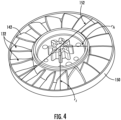
- FIG. 4 illustrates an embodiment of the fan 112 that may include an outer ring 150 surrounding the fan blades 132.
- the outer ring 150 may contact the tip end 142 of one or more of the fan blades 132, e.g., all of the fan blades 132. In this manner, during operation of the blower/vac 10, the outer ring 150 may rotate with rotation of the axial fan 112 and the motor 114.
- the outer ring 150 may have an inner diameter 152 equal to 2 r t .
- the inner diameter 152 may be generally equal to an inner diameter of the first end 102 and/or an inner diameter of the second end 104.
- the inner diameter 152 may be generally equal to both an inner diameter of the first end 102 and an inner diameter of the second end 104.
- the longitudinal axis 124 may extend through a center point of the first end 102, a center point of the outer ring 150, and a center point of the second end 104. In this manner, the airflow conduit may have a generally constant diameter along the length of the airflow conduit 106, thereby reducing disruptions to the flow within the airflow conduit.
- the blade pass frequency of the blower/vac tool 10 may correspond to the sound frequency generated by the axial fan of the tool 10.
- the number of blades, also referred to herein as n b and the rotational speed of the fan may directly influence the sound frequency generated by the blower/vac 10.
- n b the number of blades, also referred to herein as n b
- the rotational speed of the fan may directly influence the sound frequency generated by the blower/vac 10.
- n b the number of blades
- the present inventors have found that achieving a higher blade pass frequency may therefore reduce the audible noise generated by the blower/vac tool 10.
- the present inventors have found that to achieve a higher blade pass frequency above 6 KHz and therefore reduce audible noise generated, the motor rotational speed may be increased, the number of fan blades 132 may be increased, or both the motor rotational speed and the number of fan blades 132 may be increased.
- the motor may be configured to rotate at a rotational speed of between about 21000 - 38000 RPM.
- a rotational speed of between about 21000 - 38000 RPM.
- the present inventors have found that providing a blower/vac 10 having a blade pass frequency of greater than 6 KHz may be desirable.
- the blower/vac 10 may operate at a rotational motor speed as low as 21000 RPM, the present inventors have found that it may be desirable to implement a fan 112 having at least 17 fan blades 132.
- Blade Solidity is measure of fan blade spacing, which is directly influenced by the number of blades provided on a given fan.
- c is the length of the chord line of the fan blades
- r m is the mean radius of the fan blades.
- the present inventors have found that increasing the Blade Solidity of the fan 112, by increasing the number of blades, may result in a blower/vac 10 having reduced audible noise generated during operation. Further, as the number of blades n b increases, the blade solidity value may increase as well.
- the present inventors have found that ideal noise reduction may be achieved when the fan 112 of the blower/vac 10 satisfies the following conditions: n b is in a range from 17 to 45, the axial fan 112 may have a Blade Solidity in a range from 0.0464 n b ⁇ Blade Solidity ⁇ 0.089 n b .
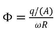
- the airflow generation assembly 110 of the present invention having an axial fan 112 may be optimized when a dimensionless flow coefficient ⁇ is in a range from about 0.2 to about 0.6.
- the size and speed of the airflow generation assembly 110 are defined as a function of the optimal flow coefficient ⁇ .
- the blower/vac 10 may generate less audible noise while maintaining optimal airflow characteristics, thereby improving the user's overall experience during operation of the blower/vac 10. For instance, reducing the audible noise generated by the blower/vac 10 may be highly desirable to users, particularly for homeowners and other non-professional users. Simultaneously, maintaining optimal airflow characteristics may enable efficient battery life of the blower/vac 10, reducing the need for users to recharge or replace the power source without reducing the power of the airflow generated during operation.
- the housing 108 may include an inlet muffler 160 disposed at the first end 102.
- the inlet muffler 160 may be disposed within the airflow conduit 106 at the first end 102.
- the inlet muffler 160 may include a liner 162 surrounding at least a portion of the airflow conduit 106.
- the liner 162 may comprise noise-absorbing material.
- the noise-absorbing material may be configured to absorb noise in a frequency range of 2-6 KHz in order to reduce the audible noise in the human hearing frequency range.
- the noise-absorbing material may include foam.
- the noise-absorbing material may include foam, such as but not limited to foam/film laminates, such as polyurethane foam.
- the liner 162 may surround an entire circumference of the air conduit 106 and/or may surround one or more portions of the circumference of the air conduit 106.
- a blower/vacuum tool includes a main body extending between a first end and a second end defining an airflow conduit therethrough; and a fan assembly.
- the fan assembly includes an axial fan having a number of fan blades ( n b ), and a motor rotatably connected to the fan.
- the motor operates at a speed of between 21000-38000 rotations per minute (RPM)
- blower/vac tool of any one or more of the embodiments, wherein the plurality of fan blades comprises from 17 to 45 fan blades.
- blower/vac tool of any one or more of the embodiments wherein the axial fan comprises a hub and the plurality of fan blades extend from the hub at a root of each respective fan blade.
- each of the plurality of fan blades terminates at a tip of each respective fan blade, the axial fan further comprising an outer ring in contact with the tip of each respective fan blade.
- blower/vac tool of any one or more of the embodiments wherein the outer ring rotates with rotation of the axial fan.
- the outer ring comprises an inner diameter, wherein the inner diameter of the outer ring is generally equal to an inner diameter of the first end and/or an inner diameter of the second end.
- blower/vac tool of any one or more of the embodiments wherein a longitudinal axis extends through a center point of the first end of the main body, a center point of the outer ring, and a center point of the second end of the main body.
- blower/vac tool of any one or more of the embodiments further comprising an inlet muffler disposed at the first end of the main body, the inlet muffler including a liner comprising noise-absorbing material configured to absorb noise in a frequency range of 2-6 KHz.
- blower/vac tool of any one or more of the embodiments, wherein the noise-absorbing material comprises foam.
- a blower/vacuum tool includes a main body extending between a first end and a second end defining an airflow conduit therethrough; and a fan assembly.
- the fan assembly includes an axial fan having a number of fan blades ( n b ), and a motor rotatably connected to the fan.
- n b is in a range from 17- 45
- each of the fan blades terminates at a tip of each respective fan blade, the axial fan further comprising an outer ring in contact with the tip of each respective fan blade.
- blower/vac tool of any one or more of the embodiments wherein the outer ring rotates with rotation of the axial fan.
- the outer ring comprises an inner diameter, wherein the inner diameter of the outer ring is generally equal to an inner diameter of the first end and/or an inner diameter of the second end.
- blower/vac tool of any one or more of the embodiments wherein a longitudinal axis extends through a center point of the first end of the main body, a center point of the outer ring, and a center point of the second end of the main body.
- blower/vac tool of any one or more of the embodiments further comprising an inlet muffler disposed at the first end of the main body, the inlet muffler including a liner comprising noise-absorbing material configured to absorb noise in a frequency range of 2-6 KHz.
- blower/vac tool of any one or more of the embodiments, wherein the noise-absorbing material comprises foam.
Landscapes
- Engineering & Computer Science (AREA)
- Mechanical Engineering (AREA)
- General Engineering & Computer Science (AREA)
- Structures Of Non-Positive Displacement Pumps (AREA)
Abstract

Description
- The present application claims priority to
U.S. Provisional patent Application No. 63/592,473 filed on October 23, 2023 - The present disclosure relates generally to outdoor tools such as blowers, vacuums and/or combined blower / vacuums, and more particularly, to improved fan blade noise in such tools.
- Outdoor tools such as blowers, vacuums, and combined blower / vacuums (collectively "blower/vac tools") are commonly used to concentrate debris, e.g., leaves, using a blowing function and/or collect debris using a sucking function. Homeowners frequently utilized such blowers to clean their yards and outdoor spaces. Such blower/vac tools being powered by a battery power source are particularly desirable due to their portability. However, improvements in various aspects of blower/vac tools, and particularly handheld blower/vac tools, are desired.
- One issue with known blower/vac tools is the noise level that is generated by the fan assembly, and particularly, the fan blase noise, of the blower/vac tool during operation. The most sensitive range of human hearing is generally between 2-6 KHz due to the alignment of the natural frequency of the ear's auditory canal, while frequencies between 8-12 KHz have significantly lower human hearing sensitivity, and frequencies of 16-20 KHz or greater are inaudible to humans. However, typical fan blade pass frequency for axial fans in leaf blowers is generally between 2.5-4 KHz, which is directly within the most sensitive range of human hearing.
- Accordingly, improved blower/vac tools are desired in the art. In particular, a blower/vac tool with reduced fan blade noise would be advantageous.
- Aspects and advantages of the present disclosure will be set forth in part in the following description, or may be obvious from the description, or may be learned through practice of the technology.
- In accordance with one embodiment, a blower/vacuum tool is provided. The blower/vacuum tool includes a main body extending between a first end and a second end defining an airflow conduit therethrough; and a fan assembly. The fan assembly includes an axial fan having a number of fan blades (nb ), and a motor rotatably connected to the fan. When nb is in a range from 17- 45, the axial fan has a Blade Solidity in a range from 0.0464nb ≤ Blade Solidity ≤ 0.089nb calculated by the equation Blade Solidity = c/s where c is the length of the chord line of the fan blades, s = 2πrm /nb , and rm is the mean radius of the fan blades.
- In accordance with another embodiment, a blower/vacuum tool is provided. The blower/vacuum tool includes a main body extending between a first end and a second end defining an airflow conduit therethrough; and a fan assembly. The fan assembly includes an axial fan having a number of fan blades (nb ), and a motor rotatably connected to the fan. When the motor operates at a speed of between 21000-38000 rotations per minute (RPM), blade pass frequency (BPF) of the fan assembly as defined by the equation

- These and other features, aspects and advantages of the present disclosure will become better understood with reference to the following description and appended claims. The accompanying drawings, which are incorporated in and constitute a part of this specification, illustrate embodiments of the technology and, together with the description, serve to explain the principles of the technology.
- A full and enabling disclosure of the present application, including the best mode of making and using the present systems and methods, directed to one of ordinary skill in the art, is set forth in the specification, which makes reference to the appended figures, in which:
-
FIG. 1 is a side view of a blower/vacuum tool in accordance with embodiments of the present disclosure; -
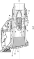
FIG. 2 is a side cross-sectional view of a blower/vacuum tool in accordance with embodiments of the present disclosure; -
FIG. 3 is a perspective view of an axial fan in accordance with embodiments of the present disclosure; -
FIG. 4 is a perspective view of an axial fan having an outer ring in accordance with embodiments of the present disclosure; and -
FIG. 5 is a graphical representation of the blade solidity of an axial fan relative to the number of fan blades of the axial fan in accordance with embodiments of the present disclosure. - Reference now will be made in detail to embodiments of the present invention, one or more examples of which are illustrated in the drawings. The word "exemplary" is used herein to mean "serving as an example, instance, or illustration." Any implementation described herein as "exemplary" is not necessarily to be construed as preferred or advantageous over other implementations. Moreover, each example is provided by way of explanation, rather than limitation of, the technology. In fact, it will be apparent to those skilled in the art that modifications and variations can be made in the present technology without departing from the scope or spirit of the claimed technology. For instance, features illustrated or described as part of one embodiment can be used with another embodiment to yield a still further embodiment. Thus, it is intended that the present disclosure covers such modifications and variations as come within the scope of the appended claims and their equivalents. The detailed description uses numerical and letter designations to refer to features in the drawings. Like or similar designations in the drawings and description have been used to refer to like or similar parts of the invention.
- As used herein, the terms "first", "second", and "third" may be used interchangeably to distinguish one component from another and are not intended to signify location or importance of the individual components. The singular forms "a," "an," and "the" include plural references unless the context clearly dictates otherwise. The terms "coupled," "fixed," "attached to," and the like refer to both direct coupling, fixing, or attaching, as well as indirect coupling, fixing, or attaching through one or more intermediate components or features, unless otherwise specified herein. As used herein, the terms "comprises," "comprising," "includes," "including," "has," "having" or any other variation thereof, are intended to cover a non-exclusive inclusion. For example, a process, method, article, or apparatus that comprises a list of features is not necessarily limited only to those features but may include other features not expressly listed or inherent to such process, method, article, or apparatus. Further, unless expressly stated to the contrary, "or" refers to an inclusive- or and not to an exclusive- or. For example, a condition A or B is satisfied by any one of the following: A is true (or present) and B is false (or not present), A is false (or not present) and B is true (or present), and both A and B are true (or present).
- Terms of approximation, such as "about," "generally," "approximately," or "substantially," include values within ten percent greater or less than the stated value. When used in the context of an angle or direction, such terms include within ten degrees greater or less than the stated angle or direction. For example, "generally vertical" includes directions within ten degrees of vertical in any direction, e.g., clockwise or counter-clockwise.
- Benefits, other advantages, and solutions to problems are described below with regard to specific embodiments. However, the benefits, advantages, solutions to problems, and any feature(s) that may cause any benefit, advantage, or solution to occur or become more pronounced are not to be construed as a critical, required, or essential feature of any or all the claims.
- In general, the present invention is directed to a blower/vacuum tool having a fan assembly that generated reduced noise during operation. The fan assembly includes an axial fan and a motor. The axial fan, including the number and size of fan blades, and the operational characteristics of the motor, including rotational speed, are optimized to reduce audible noise generated in the sensitive range of human hearing, i.e., about 2-6 KHz, by increasing the blade pass frequency of the fan assembly to frequency greater than 6 KHz.
- Referring now to the drawings,
FIG. 1 illustrates a side view of a blower/vac tool 100 in accordance with an exemplary embodiment. The blower/vac tool 100 is configured to generate airflow along anairflow conduit 106 extending between afirst end 102, e.g., an air inlet, and asecond end 104, e.g., an air outlet, of the blower/vac tool 100. Theairflow conduit 106 may include a tube as shown. - As illustrated in
FIGS. 1 and2 , ahousing 108, e.g., a main body of the blower/vac tool 100, may at least partially enclose components of the blower/vac tool 100 such as anairflow generation assembly 110 including afan 112 and amotor 114 that drives thefan 112, as well as various other components. For instance,airflow generation assembly 110 may be disposed between thefirst end 102 and thesecond end 104 of theairflow conduit 106. Power to operate theairflow generation assembly 110 may be provided by a suitable power source such as one ormore batteries 116 removably coupled to thehousing 108. The blower/vac tool 100 may be provided as a standard handheld blower/vac tool having a cordless battery powered power source. In other embodiments, the blower/vac tool may include a corded electric power source and/or a gas power source. Additionally, a blower/vac tool in accordance with the present disclosure may be a handheld blower/vac tool as shown, or may be provided as a backpack blower/vac tool (not shown) adapted to be worn on a user's back. - In exemplary embodiments, the blower/vac tool may be a blower which utilizes a blowing function, e.g., where airflow is generated from the
first end 102 as an inlet to thesecond end 104 as an outlet. In other exemplary embodiments, the blower/vac tool may be a vacuum which utilizes a sucking function, e.g., where airflow is generated from thesecond end 104 as an inlet to thefirst end 102 as an outlet. In other exemplary embodiments, the blower/vac tool may be a combination blower / vacuum which can alternate between utilizing a blowing function and a sucking function. - Still referring to
FIGS. 1 and2 , theairflow generation assembly 110 may have an axial configuration including anaxial fan 112. Themotor 114 may be mounted within thehousing 108. For instance, thehousing 108 may include amotor mount 118 configured to support themotor 114 between thefirst end 102 and thesecond end 104. Themotor 114 is oriented along a motor axis 120. The motor axis 120 coincides with alongitudinal axis 124 of the airflow conduit. Rotation of themotor 114 causes rotation of a primary motor shaft 122 extending along the motor axis 120. The motor shaft 122 is coupled to thefan 112, e.g., rotatable connected to thefan 112. In this manner, rotation of the motor shaft 122 causes rotation of thefan 112. Themotor 114 may be configured to operate at a rotational speed in a range from about 21000 rotations per minute (RPM) to about 38000 RPM. - The
fan 112 includes ahub 130 and a plurality ofblades 132. Thehub 130 may have a generally circular cross-sectional shape and may extend along the motor axis 120. The motor shaft 122 is coupled to thehub 130 and/or afan drive shaft 134 to enable transmission of rotation from themotor 114 to thehub 130 or thefan drive shaft 134 and ultimately to theblades 132. - As best seen in
FIGS. 3 and4 , eachrespective fan blade 132 extends radially away from thehub 130. Eachblade 132 extends from aroot 140 and terminates at atip end 142, and has afirst face 144 and asecond face 146 opposite thefirst face 144. Theroot 140 contacts thehub 130 of thefan 112. Thetip end 142 contacts thehub 130 at a different angular position around the circumference of thehub 130 than theroot 140. In another embodiment (not shown), thetip end 142 may contact anadjacent blade 132 of thefan 112. - As shown in
FIG. 3 andFIG. 4 , thefan 112 may have an inner radius rh defined by a radius of thehub 130, and an outer radius rt defined by a radius of the fan at thetip 142 of the blades. Thefan 112 may include any suitable number of fan blades (also referred to herein as nb ), as further described below. -
FIG. 4 illustrates an embodiment of thefan 112 that may include anouter ring 150 surrounding thefan blades 132. For instance, theouter ring 150 may contact thetip end 142 of one or more of thefan blades 132, e.g., all of thefan blades 132. In this manner, during operation of the blower/vac 10, theouter ring 150 may rotate with rotation of theaxial fan 112 and themotor 114. - In some aspects of the invention, e.g., as generally illustrated in
FIG. 2 , theouter ring 150 may have aninner diameter 152 equal to 2rt . Theinner diameter 152 may be generally equal to an inner diameter of thefirst end 102 and/or an inner diameter of thesecond end 104. For instance, theinner diameter 152 may be generally equal to both an inner diameter of thefirst end 102 and an inner diameter of thesecond end 104. Moreover, thelongitudinal axis 124 may extend through a center point of thefirst end 102, a center point of theouter ring 150, and a center point of thesecond end 104. In this manner, the airflow conduit may have a generally constant diameter along the length of theairflow conduit 106, thereby reducing disruptions to the flow within the airflow conduit. - The present inventors have found that the blade pass frequency of the blower/
vac tool 10 may correspond to the sound frequency generated by the axial fan of thetool 10. Blade pass frequency can be calculated using the equation: BPF =
vac 10. As human hearing is most sensitive to sound frequencies between 2-6 KHz, and hearing sensitivity is reduced and/or diminished above 6 KHz, the present inventors have found that achieving a higher blade pass frequency may therefore reduce the audible noise generated by the blower/vac tool 10. Based on the equation provided, the present inventors have found that to achieve a higher blade pass frequency above 6 KHz and therefore reduce audible noise generated, the motor rotational speed may be increased, the number offan blades 132 may be increased, or both the motor rotational speed and the number offan blades 132 may be increased. - In the blower/
vac 10 of the present invention, as noted above, the motor may be configured to rotate at a rotational speed of between about 21000 - 38000 RPM. As human hearing is most sensitive to sound frequencies between 2-6 KHz, the present inventors have found that providing a blower/vac 10 having a blade pass frequency of greater than 6 KHz may be desirable. Thus, when the blower/vac 10 may operate at a rotational motor speed as low as 21000 RPM, the present inventors have found that it may be desirable to implement afan 112 having at least 17fan blades 132. - Further, it may be desirable to increase the number of
fan blades 132 provided on thefan 112. Blade Solidity is measure of fan blade spacing, which is directly influenced by the number of blades provided on a given fan. Blade Solidity is defined by the equation: Blade Solidity = c/s where s = 2πrm /nb. In this equation, c is the length of the chord line of the fan blades and rm is the mean radius of the fan blades. The mean radius of the fan blades rm is calculated by the equation rm =
- The present inventors have found that increasing the Blade Solidity of the
fan 112, by increasing the number of blades, may result in a blower/vac 10 having reduced audible noise generated during operation. Further, as the number of blades nb increases, the blade solidity value may increase as well. The present inventors have found that ideal noise reduction may be achieved when thefan 112 of the blower/vac 10 satisfies the following conditions: nb is in a range from 17 to 45, theaxial fan 112 may have a Blade Solidity in a range from 0.0464nb ≤ Blade Solidity ≤ 0.089nb . - The present inventors have found that the
airflow generation assembly 110 of the present invention having anaxial fan 112 may be optimized when a dimensionless flow coefficient Φ is in a range from about 0.2 to about 0.6. The size and speed of theairflow generation assembly 110 are defined as a function of the optimal flow coefficient Φ. The flow coefficient is calculated by the following equation:
blade tip 142. Stated differently, the numerator q/(A) is the axial velocity of the fan (meters per second). - Based on the calculation of the flow coefficient Φ as shown above, the optimal size of the fan may be determined by rearranging the equation as shown below:

- By optimizing both the blade solidity and the flow coefficient of the
airflow generation assembly 110 during operation of the blower/vac 10, the present inventors have found that the blower/vac 10 may generate less audible noise while maintaining optimal airflow characteristics, thereby improving the user's overall experience during operation of the blower/vac 10. For instance, reducing the audible noise generated by the blower/vac 10 may be highly desirable to users, particularly for homeowners and other non-professional users. Simultaneously, maintaining optimal airflow characteristics may enable efficient battery life of the blower/vac 10, reducing the need for users to recharge or replace the power source without reducing the power of the airflow generated during operation. - To further reduce the audible noise generated by the blower/
vac 10 during operation, thehousing 108 may include aninlet muffler 160 disposed at thefirst end 102. For instance, theinlet muffler 160 may be disposed within theairflow conduit 106 at thefirst end 102. In some embodiments, theinlet muffler 160 may include aliner 162 surrounding at least a portion of theairflow conduit 106. Theliner 162 may comprise noise-absorbing material. In particular, the noise-absorbing material may be configured to absorb noise in a frequency range of 2-6 KHz in order to reduce the audible noise in the human hearing frequency range. The noise-absorbing material may include foam. Additionally or alternatively, the noise-absorbing material may include foam, such as but not limited to foam/film laminates, such as polyurethane foam. Theliner 162 may surround an entire circumference of theair conduit 106 and/or may surround one or more portions of the circumference of theair conduit 106. - Further aspects of the present disclosure are provided by one or more of the following embodiments:
- A blower/vacuum tool includes a main body extending between a first end and a second end defining an airflow conduit therethrough; and a fan assembly. The fan assembly includes an axial fan having a number of fan blades (nb ), and a motor rotatably connected to the fan. When the motor operates at a speed of between 21000-38000 rotations per minute (RPM), blade pass frequency (BPF) of the fan assembly as defined by the equation

- The blower/vac tool of any one or more of the embodiments, wherein the plurality of fan blades comprises from 17 to 45 fan blades.
- The blower/vac tool of any one or more of the embodiments, wherein the axial fan comprises a hub and the plurality of fan blades extend from the hub at a root of each respective fan blade.
- The blower/vac tool of any one or more of the embodiments, wherein each of the plurality of fan blades terminates at a tip of each respective fan blade, the axial fan further comprising an outer ring in contact with the tip of each respective fan blade.
- The blower/vac tool of any one or more of the embodiments, wherein the outer ring rotates with rotation of the axial fan.
- The blower/vac tool of any one or more of the embodiments, wherein the outer ring comprises an inner diameter, wherein the inner diameter of the outer ring is generally equal to an inner diameter of the first end and/or an inner diameter of the second end.
- The blower/vac tool of any one or more of the embodiments, wherein a longitudinal axis extends through a center point of the first end of the main body, a center point of the outer ring, and a center point of the second end of the main body.
- The blower/vac tool of any one or more of the embodiments, further comprising an inlet muffler disposed at the first end of the main body, the inlet muffler including a liner comprising noise-absorbing material configured to absorb noise in a frequency range of 2-6 KHz.
- The blower/vac tool of any one or more of the embodiments, wherein the noise-absorbing material comprises foam.
- The blower/vac tool of any one or more of the embodiments, wherein when the motor operates at a rotational speed of between 21000 - 38000 rotations per minute (RPM), the fan assembly has a dimensionless flow coefficient Φ in a range from about 0.3 to 0.5 as calculated by the equation

- A blower/vacuum tool includes a main body extending between a first end and a second end defining an airflow conduit therethrough; and a fan assembly. The fan assembly includes an axial fan having a number of fan blades (nb ), and a motor rotatably connected to the fan. When nb is in a range from 17- 45, the axial fan has a Blade Solidity in a range from 0.0464nb ≤ Blade Solidity ≤ 0.089nb calculated by the equation Blade Solidity = c/s where c is the length of the chord line of the fan blades, s = 2πrm /nb , and rm is the mean radius of the fan blades. The blower/vac tool of any one or more of the embodiments, wherein the axial fan comprises a hub and each of the fan blades extends from the hub at a root of each respective fan blade.
- The blower/vac tool of any one or more of the embodiments, wherein each of the fan blades terminates at a tip of each respective fan blade, the axial fan further comprising an outer ring in contact with the tip of each respective fan blade.
- The blower/vac tool of any one or more of the embodiments, wherein the outer ring rotates with rotation of the axial fan.
- The blower/vac tool of any one or more of the embodiments, wherein the outer ring comprises an inner diameter, wherein the inner diameter of the outer ring is generally equal to an inner diameter of the first end and/or an inner diameter of the second end.
- The blower/vac tool of any one or more of the embodiments, wherein a longitudinal axis extends through a center point of the first end of the main body, a center point of the outer ring, and a center point of the second end of the main body.
- The blower/vac tool of any one or more of the embodiments, further comprising an inlet muffler disposed at the first end of the main body, the inlet muffler including a liner comprising noise-absorbing material configured to absorb noise in a frequency range of 2-6 KHz.
- The blower/vac tool of any one or more of the embodiments, wherein the noise-absorbing material comprises foam.
- The blower/vac tool of any one or more of the embodiments, wherein when the motor operates at a rotational speed of between 21000 - 38000 rotations per minute (RPM), the fan assembly has a dimensionless flow coefficient Φ in a range from about 0.3 to 0.5 as calculated by the equation

- This written description uses examples to disclose the invention, including the best mode, and also to enable any person skilled in the art to practice the invention, including making and using any devices or systems and performing any incorporated methods. The patentable scope of the invention is defined by the claims, and may include other examples that occur to those skilled in the art. Such other examples are intended to be within the scope of the claims if they include structural elements that do not differ from the literal language of the claims, or if they include equivalent structural elements with insubstantial differences from the literal language of the claims.
Claims (19)
- A blower/vac tool comprising:a main body defining an airflow conduit therethrough, the main body extending between a first end and a second end; anda fan assembly disposed between the first end and the second end, the fan assembly comprising an axial fan having a plurality of fan blades, and a motor rotatably connected to the fan;wherein when the motor operates at a rotational speed of between 21000-38000 rotations per minute (RPM), blade pass frequency (BPF) of the fan assembly as defined by the equation

- The blower/vac tool of claim 1, wherein the plurality of fan blades comprises from 17 to 45 fan blades.
- The blower/vac tool of claim 1, wherein the axial fan comprises a hub and the plurality of fan blades extend from the hub at a root of each respective fan blade.
- The blower/vac tool of claim 3, wherein each of the plurality of fan blades terminates at a tip of each respective fan blade, the axial fan further comprising an outer ring in contact with the tip of each respective fan blade.
- The blower/vac tool of claim 4, wherein the outer ring rotates with rotation of the axial fan.
- The blower/vac tool of claim 4, wherein the outer ring comprises an inner diameter, wherein the inner diameter of the outer ring is generally equal to an inner diameter of the first end and/or an inner diameter of the second end.
- The blower/vac tool of claim 4, wherein a longitudinal axis extends through a center point of the first end of the main body, a center point of the outer ring, and a center point of the second end of the main body.
- The blower/vac tool of claim 1, further comprising an inlet muffler disposed at the first end of the main body, the inlet muffler including a liner comprising noise-absorbing material configured to absorb noise in a frequency range of 2-6 KHz.
- The blower/vac tool of claim 8, wherein the noise-absorbing material comprises foam.
- The blower/vac tool of claim 1, wherein when the motor operates at a rotational speed of between 21000 - 38000 rotations per minute (RPM), the fan assembly has a dimensionless flow coefficient Φ in a range from about 0.3 to 0.5 as calculated by the equation
- A blower/vac tool comprising:a main body defining an airflow conduit therethrough, the main body extending between a first end and a second end; anda fan assembly disposed between the first end and the second end, wherein the fan assembly comprises an axial fan having a number of fan blades (nb ), and a motor rotatably connected to the fan;wherein when nb is in a range from 17 to 45, the axial fan has a Blade Solidity in a range from 0.0464nb ≤ Blade Solidity ≤ 0.089nb as calculated by the equation Blade Solidity = c/s where c is the length of the chord line of the fan blades, s = 2πrm /nb , and rm is the mean radius of the fan blades.
- The blower/vac tool of claim 11, wherein the axial fan comprises a hub and each of the fan blades extends from the hub at a root of each respective fan blade.
- The blower/vac tool of claim 12, wherein each of the fan blades terminates at a tip of each respective fan blade, the axial fan further comprising an outer ring in contact with the tip of each respective fan blade.
- The blower/vac tool of claim 13, wherein the outer ring rotates with rotation of the axial fan.
- The blower/vac tool of claim 13, wherein the outer ring comprises an inner diameter, wherein the inner diameter of the outer ring is generally equal to an inner diameter of the first end and/or an inner diameter of the second end.
- The blower/vac tool of claim 13, wherein a longitudinal axis extends through a center point of the first end of the main body, a center point of the outer ring, and a center point of the second end of the main body.
- The blower/vac tool of claim 11, further comprising an inlet muffler disposed at the first end of the main body, the inlet muffler including a liner comprising noise-absorbing material configured to absorb noise in a frequency range of 2-6 KHz.
- The blower/vac tool of claim 17, wherein the noise-absorbing material comprises foam.
- The blower/vac tool of claim 11, wherein when the motor operates at a rotational speed of between 21000 - 38000 rotations per minute (RPM), the fan assembly has a dimensionless flow coefficient Φ in a range from about 0.3 to 0.5 as calculated by the equation

Applications Claiming Priority (1)
| Application Number | Priority Date | Filing Date | Title |
|---|---|---|---|
| US202363592473P | 2023-10-23 | 2023-10-23 |
Publications (2)
| Publication Number | Publication Date |
|---|---|
| EP4545795A2 true EP4545795A2 (en) | 2025-04-30 |
| EP4545795A3 EP4545795A3 (en) | 2025-07-09 |
Family
ID=93214098
Family Applications (1)
| Application Number | Title | Priority Date | Filing Date |
|---|---|---|---|
| EP24207763.4A Pending EP4545795A3 (en) | 2023-10-23 | 2024-10-21 | Blower / vac tools with improved fan blade noise |
Country Status (3)
| Country | Link |
|---|---|
| US (1) | US12704128B2 (en) |
| EP (1) | EP4545795A3 (en) |
| CN (1) | CN223634938U (en) |
Family Cites Families (14)
| Publication number | Priority date | Publication date | Assignee | Title |
|---|---|---|---|---|
| US6386830B1 (en) | 2001-03-13 | 2002-05-14 | The United States Of America As Represented By The Secretary Of The Navy | Quiet and efficient high-pressure fan assembly |
| US7168918B2 (en) * | 2004-09-30 | 2007-01-30 | General Electric Company | High performance cooling fan |
| US10227988B2 (en) * | 2014-11-28 | 2019-03-12 | Positec Power Tools (Suzhou) Co., Ltd. | Blower and a blowing vacuum device |
| EP3626972B1 (en) * | 2018-09-21 | 2023-05-10 | Techtronic Outdoor Products Technology Limited | Electric blower |
| KR20210137750A (en) | 2020-05-11 | 2021-11-18 | 엘지전자 주식회사 | Hair dryer |
| CN119498159A (en) * | 2020-09-29 | 2025-02-25 | 苏州宝时得电动工具有限公司 | Garden hair dryer |
| WO2022147300A1 (en) * | 2020-12-30 | 2022-07-07 | Milwaukee Electric Tool Corporation | Handheld blower |
| CN115075178A (en) | 2021-03-12 | 2022-09-20 | 苏州宝时得电动工具有限公司 | Garden tool with blowing function |
| JP7650200B2 (en) * | 2021-06-25 | 2025-03-24 | 株式会社やまびこ | Axial Flow Blower |
| US12352274B2 (en) * | 2022-03-21 | 2025-07-08 | Milwaukee Electric Tool Corporation | Axial blower |
| CN217976712U (en) | 2022-06-27 | 2022-12-06 | 深圳汝原科技有限公司 | Blade, propeller and drying equipment |
| EP4560140A4 (en) * | 2022-07-18 | 2026-01-14 | Greenworks Jiangsu Co Ltd | AXIAL BLOWER |
| EP4530405B1 (en) * | 2022-08-12 | 2026-05-27 | Nanjing Chervon Industry Co., Ltd. | Air flow device |
| CN122580002A (en) * | 2023-09-20 | 2026-08-14 | 耳语航空公司 | Air-moving device, pneumatic rotor and method |
-
2024
- 2024-10-09 US US18/910,083 patent/US12704128B2/en active Active
- 2024-10-21 EP EP24207763.4A patent/EP4545795A3/en active Pending
- 2024-10-22 CN CN202422555175.0U patent/CN223634938U/en active Active
Also Published As
| Publication number | Publication date |
|---|---|
| US20250129794A1 (en) | 2025-04-24 |
| US12704128B2 (en) | 2026-08-11 |
| CN223634938U (en) | 2025-12-05 |
| EP4545795A3 (en) | 2025-07-09 |
Similar Documents
| Publication | Publication Date | Title |
|---|---|---|
| CN112303032B (en) | Blower with noise reduction features | |
| EP2543889B1 (en) | Electric blower and electric cleaner using same | |
| JP7389779B2 (en) | Breathing assistance systems and blowers for breathing assistance systems | |
| US12288544B2 (en) | Power tool having noise reduction features | |
| EP3225742B1 (en) | Air blower and blower/vacuum apparatus | |
| US9850915B2 (en) | Power tool | |
| WO2019094168A1 (en) | A blower impeller for a handheld blower | |
| US20150224656A1 (en) | Hair trimmer with vacuum collection system | |
| JP2008303793A (en) | Electric blower, electric vacuum cleaner using the same | |
| US20250129794A1 (en) | Blower / vac tools with improved fan blade noise | |
| ES2491102T3 (en) | Hair dryer with centrifugal fan | |
| US20250180040A1 (en) | Blower | |
| JP2016033338A (en) | Centrifugal blower | |
| CN223136437U (en) | A ventilation device | |
| EP4400726A1 (en) | Fan shroud and fan assembly having fan shroud | |
| JP3331878B2 (en) | Electric vacuum cleaner | |
| US20090148294A1 (en) | Houseless fan with rotating tip ring as silencer | |
| US20250127101A1 (en) | Walk-behind blower | |
| JP3888504B2 (en) | Electric blower and vacuum cleaner | |
| JP2001304172A (en) | Electric blower and vacuum cleaner | |
| PH12022050337A1 (en) | Axial fan | |
| JPH0635478A (en) | Vacuum cleaner | |
| JPH10176852A (en) | Tunnel ventilation fan | |
| CN112032103B (en) | Impeller, air supply device and dust collector | |
| JP5012096B2 (en) | Electric blower and electric vacuum cleaner using the same |
Legal Events
| Date | Code | Title | Description |
|---|---|---|---|
| PUAI | Public reference made under article 153(3) epc to a published international application that has entered the european phase |
Free format text: ORIGINAL CODE: 0009012 |
|
| STAA | Information on the status of an ep patent application or granted ep patent |
Free format text: STATUS: THE APPLICATION HAS BEEN PUBLISHED |
|
| AK | Designated contracting states |
Kind code of ref document: A2 Designated state(s): AL AT BE BG CH CY CZ DE DK EE ES FI FR GB GR HR HU IE IS IT LI LT LU LV MC ME MK MT NL NO PL PT RO RS SE SI SK SM TR |
|
| PUAL | Search report despatched |
Free format text: ORIGINAL CODE: 0009013 |
|
| AK | Designated contracting states |
Kind code of ref document: A3 Designated state(s): AL AT BE BG CH CY CZ DE DK EE ES FI FR GB GR HR HU IE IS IT LI LT LU LV MC ME MK MT NL NO PL PT RO RS SE SI SK SM TR |
|
| RIC1 | Information provided on ipc code assigned before grant |
Ipc: F04D 29/66 20060101ALI20250603BHEP Ipc: F04D 29/32 20060101ALI20250603BHEP Ipc: F04D 19/00 20060101AFI20250603BHEP |
|
| STAA | Information on the status of an ep patent application or granted ep patent |
Free format text: STATUS: REQUEST FOR EXAMINATION WAS MADE |
|
| 17P | Request for examination filed |
Effective date: 20260109 |