EP4545697A1 - Wasserführungssystem für eine waschmaschine oder einen waschtrockner - Google Patents
Wasserführungssystem für eine waschmaschine oder einen waschtrockner Download PDFInfo
- Publication number
- EP4545697A1 EP4545697A1 EP24207826.9A EP24207826A EP4545697A1 EP 4545697 A1 EP4545697 A1 EP 4545697A1 EP 24207826 A EP24207826 A EP 24207826A EP 4545697 A1 EP4545697 A1 EP 4545697A1
- Authority
- EP
- European Patent Office
- Prior art keywords
- conduit
- main
- supply
- valve
- water
- Prior art date
- Legal status (The legal status is an assumption and is not a legal conclusion. Google has not performed a legal analysis and makes no representation as to the accuracy of the status listed.)
- Pending
Links
Images




Classifications
-
- D—TEXTILES; PAPER
- D06—TREATMENT OF TEXTILES OR THE LIKE; LAUNDERING; FLEXIBLE MATERIALS NOT OTHERWISE PROVIDED FOR
- D06F—LAUNDERING, DRYING, IRONING, PRESSING OR FOLDING TEXTILE ARTICLES
- D06F39/00—Details of washing machines not specific to a single type of machines covered by groups D06F9/00 - D06F27/00
- D06F39/08—Liquid supply or discharge arrangements
- D06F39/088—Liquid supply arrangements
-
- D—TEXTILES; PAPER
- D06—TREATMENT OF TEXTILES OR THE LIKE; LAUNDERING; FLEXIBLE MATERIALS NOT OTHERWISE PROVIDED FOR
- D06F—LAUNDERING, DRYING, IRONING, PRESSING OR FOLDING TEXTILE ARTICLES
- D06F25/00—Washing machines with receptacles, e.g. perforated, having a rotary movement, e.g. oscillatory movement, the receptacle serving both for washing and for centrifugally separating water from the laundry and having further drying means, e.g. using hot air
-
- D—TEXTILES; PAPER
- D06—TREATMENT OF TEXTILES OR THE LIKE; LAUNDERING; FLEXIBLE MATERIALS NOT OTHERWISE PROVIDED FOR
- D06F—LAUNDERING, DRYING, IRONING, PRESSING OR FOLDING TEXTILE ARTICLES
- D06F39/00—Details of washing machines not specific to a single type of machines covered by groups D06F9/00 - D06F27/00
- D06F39/02—Devices for adding soap or other washing agents
- D06F39/028—Arrangements for selectively supplying water to detergent compartments
Definitions
- the present invention relates to a water conducting system for the controlled supply of a plurality of conduits, as well as to a water-conducting household appliance, in particular a domestic washing machine and washer-dryer.
- domestic washing machines and washer-dryers comprise a very complex and expensive hydraulic structure, with an undesirably high number of electric valves, or with electric valves with multiple outlets, for example three-way electric valves, in particular, but not exclusively, for the following functions and combinations of functions:
- a water conducting system for the controlled supply of a plurality of conduits, for example in a water-conducting household appliance, comprises:
- This new hydraulic and control configuration allows supplying a greater number of conduits and functions with a smaller number of supply electric valves and/or with multi-way electric valves with a smaller number of outlets. This reduces the manufacturing cost of the water conducting system and of the household appliance in which it is implemented.
- the invention further relates to a water-conducting household appliance, in particular a washing machine or washer-dryer, comprising the water conducting system.
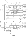
- a water conducting system 1 for the controlled supply of a plurality of conduits, for example in a water-conducting household appliance 2, comprises:
- This new hydraulic and control configuration allows supplying a greater number of conduits and functions with a smaller number of supply electric valves and/or with multi-way electric valves with a smaller number of outlets. This reduces the manufacturing cost of the water conducting system and of the household appliance in which it is implemented.
- the first main conduit 8 forms an inlet segment 18 in the first branching section 11 and an outlet segment 19 from the first branching section 11, substantially (straight and) aligned with each other or having an angular misalignment of less than 45°, preferably less than 15°, seen in the direction of the first main flow 9.
- the first secondary conduit 10 has an angular misalignment 20 greater than 90° with respect to the inlet segment 18, seen in the direction of the first main flow 9,
- the angular misalignment between the first secondary conduit 10 and the inlet segment 18 prevents or limits a branching of a partial flow from the first main flow 9 into the first secondary conduit 10.
- the first main conduit 8 forms a constriction 21 at the first branching section 11 so that the first main flow 9, acting as a driving flow, generates a Venturi suction effect on the first secondary conduit 10.
- the Venturi effect prevents or further limits a branching of a partial flow from the first main flow 9 into the first secondary conduit 10.
- an unwanted emptying of the first buffer container section 13, and therefore a residue of the first secondary flow 12, when switching from the first main mode C1P to the first OFF mode C1OFF, can be (at least temporarily) prevented or reduced by means of a backflow preventing device (not shown), for example:
- the first main conduit 8 forms a first main air gap 22 downstream of the first buffer container section 13 and upstream of the first main use 16.
- the first main air gap 22 prevents the formation of a depression in the first main conduit 8 and allows the establishment of the backflow from the first buffer container section 13 through the first branching section 11 into the first secondary conduit 10.
- the first secondary conduit 10 forms a first secondary air gap 23 upstream of the first secondary use 17.
- the first secondary air gap 23 prevents the generation of a depression in the first secondary conduit 10.
- the first main conduit 8 continuously extends from below upwards, for example with an ascent angle 24 with respect to a horizontal direction in the range from 0° to 60°, preferably from 0° to 45°, (in the direction of the first main flow 9) until downstream of the first buffer container section 13, preferably up to the first main air gap 22 or up to the first main use 16. This ensures a gravitational backflow during the operation in the first secondary mode C1.1S.
- the first branching section 11, the inlet segment 18, and the outlet segment 19 of the first main conduit 8 are aligned and form a straight conduit segment 25 oriented from below upwards (in the direction of the first main flow 9), preferably with an ascent angle 24 in the range from 15° to 60°, preferably from 15° to 45°.
- the first secondary conduit 10 continuously extends from above downwards, for example with a descent angle 27 with respect to a horizontal direction in the range from 0° to 90°, preferably from 0° to 45°, (in the direction of the first secondary flow 12), preferably up to the first secondary air gap 23 or up to the first secondary use 17. This ensures a gravitational first secondary flow 9 during the operation in the first secondary mode C1.1S.
- the first secondary conduit 10 comprises an initial segment 26 directly branching from the first branching section 11 and oriented from above downwards, with a descent angle 27 with respect to a vertical direction in the range from 0° to 15°.
- the straight conduit segment 25 and the initial segment 26 extend in a common vertical plane.
- the first valve inlet 4 and the first valve outlet 6 have a substantially horizontal orientation.
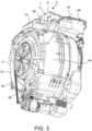
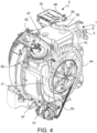
- the first branching section 11 and the first buffer container section 13 are formed in a conduction body 28, for example made of an injection-molded plastic material, for example closable or closed above by means of a covering wall 29, and forming a tubular main inlet connector 30, a tubular main outlet connector 31 and a tubular secondary outlet connector 32, preferably in a single piece ( Figures 5 , 7 ).
- a conduction body 28 for example made of an injection-molded plastic material, for example closable or closed above by means of a covering wall 29, and forming a tubular main inlet connector 30, a tubular main outlet connector 31 and a tubular secondary outlet connector 32, preferably in a single piece ( Figures 5 , 7 ).
- the conduction body 28 has a box-like shape and the first buffer container section 13 also has a box-like shape, delimited by a bottom wall 33, an opposite upper covering wall 29, and a side wall 34.
- the conduction body 28 forms, seen from the outside, at least a first cavity 35 intended to partially accommodate a protuberance of a detergent basin of a washing machine or washer-dryer, and/or at least a second cavity 36 intended to at least partially accommodate a protuberance of a ballast mass of a washing machine or washer-dryer, and/or at least one tube passage cavity 37 which keeps a passage space free for at least one further conduit of the system 1. This allows minimizing the space occupied by the system 1 inside the household appliance 2 and maximizing the useful volume of the first buffer container section 13.
- the first supply valve 3 is a multi-way valve with said at least a first valve outlet 6 and:
- the system 1 may comprise: B.1) at least one or more further first conduit systems 7.1, configured according to the embodiments described with reference to the first conduit system 7, and not repeated herein for brevity, wherein the further first conduit system 7.1 together with the first supply electric valve 3 forms a further first multiple conduction assembly 42.1.
- Said at least one or more further first conduit systems 7.1 comprise:
- the further first conduit system 7.1 together with the first supply electric valve 3 constitutes a further first multiple conduction assembly 42.1.
- the electronic control system 15 is configured to switch the first supply valve 3, i.e., the further first multiple conduction assembly 42.1:
- the first supply valve 3 is a multi-way valve with said at least a first valve outlet 6, possibly one or more further first valve outlets 6.1, and:
- the system 1 may comprise:
- the system comprises one or more second one-way or multi-way supply electric valves 43, selectively controllable by the electronic control system 15 and connected/connectable by means of one or more respective second conduits 39 to one or more respective second uses 40, possibly with the interposition of one or more respective second air gaps 41.
- the invention also relates to a water-conducting household appliance 2, in particular a washing machine and/or washer-dryer, comprising the water conducting system 1 described above.
- the washing machine and washer-dryer comprises a support and housing structure 43, inside which a tank 44 is housed, provided with a front or upper opening, closable by means of a door 45 hinged frontally or above with respect to the support and housing structure 43.
- a drum 46 for accommodating the laundry to be washed and/or dried is housed inside the tank in a rotatable manner, for example, about a horizontal or inclined rotation axis.
- the drum 46 also delimits a front opening placed at the opening of the tank 44 or a side opening positionable at the opening of the tank 44, so as to load and unload the laundry.
- the tank 44 is adapted to contain the washing liquid during the laundry washing steps and, in the case of the washer-dryer, it constitutes a portion of a drying circuit 47 during a laundry drying step.
- the household appliance 2 comprises the water conducting system 1, connectable to the water mains 5.
- the water conducting system 1 is configured to selectively adjust the supply of a plurality of flow paths through respective compartments of a detergent basin 48 up to the tank 44.
- a drainage conduit 49 associated with a drainage pump 50 is provided at the bottom of the tank 44, which removes the washing liquid from the tank 44 and, together with the control system 15 of the water conducting system 1, controls the level of liquid inside the tank 44.
- An electrical resistor 49 for heating the washing liquid contained in the tank 44 is provided, the electrical resistor being arranged inside the tank 44, in the gap between the wall of the tank 44 and the drum 46.
- the drying circuit 47 of the washer-dryer comprises a fan assembly 50, a heat exchanger 51 (aimed at condensing humidity) and a heating assembly 52 (with electrical resistor or heat pump) communicating with each other by means of a drying conduit 53.
- the air flow caused by the fan assembly 50 is heated by the heating assembly 52 and is conveyed into the drum 46, wherein, passing through the wet laundry, it causes the evaporation of the water contained in the fabrics.
- the heat exchanger 51 generally of the spray or sprinkler type, the humid air is cooled by a flow of cold water. Due to the cooling, the steam condenses and is collected and drained together with the cooling water. The dehumidified air is then sucked up again by the suction assembly 50 and recirculated.
- washing machine and/or washer-dryer may also comprise a steam generator 54 for the laundry steam treatment, also supplied by the water conducting system 1.
- the first main conduit 8, or the tubular main outlet connector 31 of the conduction body 28 is connected to the detergent basin 48 or to a multi-dosage or self-dosing detergent dispenser (which therefore forms the first main use 16), to supply the detergent basin 48 or the multi-dosage detergent dispenser with water for one or more or all of the washing and/or pre-washing and/or fabric softener steps (washing machine or washer-dryer), whereas the first secondary conduit 10, or the tubular secondary outlet connector 32 of the conduction body 28, is connected:
- the further first main conduit 8.1, or the respective tubular main outlet connector 31 of the conduction body 28 is connected to the detergent basin 48 or to a multi-dosage or self-dosing detergent dispenser (which therefore forms the further first main use 16.1), to supply the detergent basin 48 or the multi-dosage detergent dispenser with water for one or more or all of the washing and/or pre-washing and/or fabric softener steps (washing machine or washer-dryer), whereas the further first secondary conduit 10.1, or the relative tubular secondary outlet connector 32 of the conduction body 28, is connected:
- the first (or further first) main conduit 8 (or 8.1), or the tubular main outlet connector 31 of the conduction body 28 is connected to a washing inlet of the detergent basin 48 or of a multi-dosage or self-dosing detergent dispenser (which therefore forms the first or further first main use 16 or 16.1), to supply the detergent basin 48 or the multi-dosage detergent dispenser with water for a washing step (washing machine or washer-dryer), whereas the first (or further first) secondary conduit 10 (or 10.1), or the tubular secondary outlet connector 32 of the conduction body 28, is connected to a fabric softener inlet of the detergent basin 48 or of the multi-dosage or self-dosing detergent dispenser (which therefore forms the first or further first secondary use 17 or 17.1), to supply the detergent basin 48 or the multi-dosage detergent dispenser with water for a fabric softener step (washing machine or washer-dryer).
Landscapes
- Engineering & Computer Science (AREA)
- Textile Engineering (AREA)
- Detail Structures Of Washing Machines And Dryers (AREA)
Applications Claiming Priority (1)
| Application Number | Priority Date | Filing Date | Title |
|---|---|---|---|
| IT202300022512 | 2023-10-26 |
Publications (1)
| Publication Number | Publication Date |
|---|---|
| EP4545697A1 true EP4545697A1 (de) | 2025-04-30 |
Family
ID=89573926
Family Applications (1)
| Application Number | Title | Priority Date | Filing Date |
|---|---|---|---|
| EP24207826.9A Pending EP4545697A1 (de) | 2023-10-26 | 2024-10-21 | Wasserführungssystem für eine waschmaschine oder einen waschtrockner |
Country Status (1)
| Country | Link |
|---|---|
| EP (1) | EP4545697A1 (de) |
Citations (3)
| Publication number | Priority date | Publication date | Assignee | Title |
|---|---|---|---|---|
| DE1949721U (de) * | 1966-04-01 | 1966-11-17 | Constructa Werke G M B H | Waschmaschine. |
| US20130263630A1 (en) * | 2012-04-06 | 2013-10-10 | Youngjin DOH | Laundry treating machine |
| EP2860301A1 (de) * | 2013-10-11 | 2015-04-15 | Candy S.p.A. | Waschmaschine |
-
2024
- 2024-10-21 EP EP24207826.9A patent/EP4545697A1/de active Pending
Patent Citations (3)
| Publication number | Priority date | Publication date | Assignee | Title |
|---|---|---|---|---|
| DE1949721U (de) * | 1966-04-01 | 1966-11-17 | Constructa Werke G M B H | Waschmaschine. |
| US20130263630A1 (en) * | 2012-04-06 | 2013-10-10 | Youngjin DOH | Laundry treating machine |
| EP2860301A1 (de) * | 2013-10-11 | 2015-04-15 | Candy S.p.A. | Waschmaschine |
Similar Documents
| Publication | Publication Date | Title |
|---|---|---|
| RU2528354C2 (ru) | Электроприбор для сушки белья | |
| US10941514B2 (en) | Drying apparatus and laundry drying machine including the same | |
| CN201144347Y (zh) | 洗衣机 | |
| EP1889967B1 (de) | Textilienbehandlungsvorrichtung unter Verwendung von Dampf | |
| EP2775028A2 (de) | Wäschebehandlungsvorrichtung | |
| EP2471994A1 (de) | Vorrichtung zum Wäschetrocknen | |
| EP1889965A2 (de) | Dampffaserverarbeitungsvorrichtung mit Abgas | |
| EP2471998B1 (de) | Vorrichtung zum Wäschetrocknen | |
| WO2014041097A1 (en) | Home appliance with a liquid guiding device | |
| EP1889962B1 (de) | Gewebebehandlungsvorrichtung mit Absaugschutz | |
| WO2007126225A1 (en) | Clothes refreshing apparatus | |
| US7204039B2 (en) | Washing machine having a condensing duct | |
| EP2019160B1 (de) | Wäschetrockner | |
| EP4545697A1 (de) | Wasserführungssystem für eine waschmaschine oder einen waschtrockner | |
| EP1621662A2 (de) | Waschmachine | |
| US20080040869A1 (en) | Determining Fabric Temperature in a Fabric Treating Appliance | |
| JP4790039B2 (ja) | 洗濯乾燥機 | |
| RU2517009C2 (ru) | Стиральная машина с сушкой, в которой конденсационное устройство встроено в стиральный блок | |
| EP2019164B1 (de) | Wasch- und Trockenmaschine | |
| EP3450615B1 (de) | Trockner und verfahren zur herstellung eines trockners | |
| KR101594369B1 (ko) | 의류처리장치 | |
| RU2751686C2 (ru) | Устройство для обработки белья | |
| US20240254679A1 (en) | Floating ventilation interface for suds | |
| EP3077587B1 (de) | Wasch- und trocknungsvorrichtung für den haushalt | |
| JP7671204B2 (ja) | 衣類処理装置 |
Legal Events
| Date | Code | Title | Description |
|---|---|---|---|
| PUAI | Public reference made under article 153(3) epc to a published international application that has entered the european phase |
Free format text: ORIGINAL CODE: 0009012 |
|
| STAA | Information on the status of an ep patent application or granted ep patent |
Free format text: STATUS: THE APPLICATION HAS BEEN PUBLISHED |
|
| AK | Designated contracting states |
Kind code of ref document: A1 Designated state(s): AL AT BE BG CH CY CZ DE DK EE ES FI FR GB GR HR HU IE IS IT LI LT LU LV MC ME MK MT NL NO PL PT RO RS SE SI SK SM TR |
|
| STAA | Information on the status of an ep patent application or granted ep patent |
Free format text: STATUS: REQUEST FOR EXAMINATION WAS MADE |
|
| 17P | Request for examination filed |
Effective date: 20250904 |