EP4545684A1 - Pyrolyzed composite catalysts - Google Patents
Pyrolyzed composite catalysts Download PDFInfo
- Publication number
- EP4545684A1 EP4545684A1 EP23383098.3A EP23383098A EP4545684A1 EP 4545684 A1 EP4545684 A1 EP 4545684A1 EP 23383098 A EP23383098 A EP 23383098A EP 4545684 A1 EP4545684 A1 EP 4545684A1
- Authority
- EP
- European Patent Office
- Prior art keywords
- composite catalyst
- pyrolyzed
- electrode
- metal alloy
- pyrolyzed composite
- Prior art date
- Legal status (The legal status is an assumption and is not a legal conclusion. Google has not performed a legal analysis and makes no representation as to the accuracy of the status listed.)
- Withdrawn
Links
Images

Classifications
-
- C—CHEMISTRY; METALLURGY
- C25—ELECTROLYTIC OR ELECTROPHORETIC PROCESSES; APPARATUS THEREFOR
- C25B—ELECTROLYTIC OR ELECTROPHORETIC PROCESSES FOR THE PRODUCTION OF COMPOUNDS OR NON-METALS; APPARATUS THEREFOR
- C25B1/00—Electrolytic production of inorganic compounds or non-metals
- C25B1/01—Products
- C25B1/02—Hydrogen or oxygen
- C25B1/04—Hydrogen or oxygen by electrolysis of water
-
- C—CHEMISTRY; METALLURGY
- C25—ELECTROLYTIC OR ELECTROPHORETIC PROCESSES; APPARATUS THEREFOR
- C25B—ELECTROLYTIC OR ELECTROPHORETIC PROCESSES FOR THE PRODUCTION OF COMPOUNDS OR NON-METALS; APPARATUS THEREFOR
- C25B1/00—Electrolytic production of inorganic compounds or non-metals
- C25B1/01—Products
- C25B1/23—Carbon monoxide or syngas
-
- C—CHEMISTRY; METALLURGY
- C25—ELECTROLYTIC OR ELECTROPHORETIC PROCESSES; APPARATUS THEREFOR
- C25B—ELECTROLYTIC OR ELECTROPHORETIC PROCESSES FOR THE PRODUCTION OF COMPOUNDS OR NON-METALS; APPARATUS THEREFOR
- C25B11/00—Electrodes; Manufacture thereof not otherwise provided for
- C25B11/04—Electrodes; Manufacture thereof not otherwise provided for characterised by the material
- C25B11/051—Electrodes formed of electrocatalysts on a substrate or carrier
- C25B11/052—Electrodes comprising one or more electrocatalytic coatings on a substrate
-
- C—CHEMISTRY; METALLURGY
- C25—ELECTROLYTIC OR ELECTROPHORETIC PROCESSES; APPARATUS THEREFOR
- C25B—ELECTROLYTIC OR ELECTROPHORETIC PROCESSES FOR THE PRODUCTION OF COMPOUNDS OR NON-METALS; APPARATUS THEREFOR
- C25B11/00—Electrodes; Manufacture thereof not otherwise provided for
- C25B11/04—Electrodes; Manufacture thereof not otherwise provided for characterised by the material
- C25B11/051—Electrodes formed of electrocatalysts on a substrate or carrier
- C25B11/055—Electrodes formed of electrocatalysts on a substrate or carrier characterised by the substrate or carrier material
- C25B11/057—Electrodes formed of electrocatalysts on a substrate or carrier characterised by the substrate or carrier material consisting of a single element or compound
- C25B11/065—Carbon
-
- C—CHEMISTRY; METALLURGY
- C25—ELECTROLYTIC OR ELECTROPHORETIC PROCESSES; APPARATUS THEREFOR
- C25B—ELECTROLYTIC OR ELECTROPHORETIC PROCESSES FOR THE PRODUCTION OF COMPOUNDS OR NON-METALS; APPARATUS THEREFOR
- C25B11/00—Electrodes; Manufacture thereof not otherwise provided for
- C25B11/04—Electrodes; Manufacture thereof not otherwise provided for characterised by the material
- C25B11/051—Electrodes formed of electrocatalysts on a substrate or carrier
- C25B11/073—Electrodes formed of electrocatalysts on a substrate or carrier characterised by the electrocatalyst material
- C25B11/091—Electrodes formed of electrocatalysts on a substrate or carrier characterised by the electrocatalyst material consisting of at least one catalytic element and at least one catalytic compound; consisting of two or more catalytic elements or catalytic compounds
- C25B11/095—Electrodes formed of electrocatalysts on a substrate or carrier characterised by the electrocatalyst material consisting of at least one catalytic element and at least one catalytic compound; consisting of two or more catalytic elements or catalytic compounds at least one of the compounds being organic
-
- C—CHEMISTRY; METALLURGY
- C25—ELECTROLYTIC OR ELECTROPHORETIC PROCESSES; APPARATUS THEREFOR
- C25B—ELECTROLYTIC OR ELECTROPHORETIC PROCESSES FOR THE PRODUCTION OF COMPOUNDS OR NON-METALS; APPARATUS THEREFOR
- C25B13/00—Diaphragms; Spacing elements
- C25B13/02—Diaphragms; Spacing elements characterised by shape or form
-
- C—CHEMISTRY; METALLURGY
- C25—ELECTROLYTIC OR ELECTROPHORETIC PROCESSES; APPARATUS THEREFOR
- C25B—ELECTROLYTIC OR ELECTROPHORETIC PROCESSES FOR THE PRODUCTION OF COMPOUNDS OR NON-METALS; APPARATUS THEREFOR
- C25B3/00—Electrolytic production of organic compounds
- C25B3/01—Products
- C25B3/03—Acyclic or carbocyclic hydrocarbons
-
- C—CHEMISTRY; METALLURGY
- C25—ELECTROLYTIC OR ELECTROPHORETIC PROCESSES; APPARATUS THEREFOR
- C25B—ELECTROLYTIC OR ELECTROPHORETIC PROCESSES FOR THE PRODUCTION OF COMPOUNDS OR NON-METALS; APPARATUS THEREFOR
- C25B3/00—Electrolytic production of organic compounds
- C25B3/20—Processes
- C25B3/25—Reduction
- C25B3/26—Reduction of carbon dioxide
-
- C—CHEMISTRY; METALLURGY
- C25—ELECTROLYTIC OR ELECTROPHORETIC PROCESSES; APPARATUS THEREFOR
- C25B—ELECTROLYTIC OR ELECTROPHORETIC PROCESSES FOR THE PRODUCTION OF COMPOUNDS OR NON-METALS; APPARATUS THEREFOR
- C25B9/00—Cells or assemblies of cells; Constructional parts of cells; Assemblies of constructional parts, e.g. electrode-diaphragm assemblies; Process-related cell features
- C25B9/17—Cells comprising dimensionally-stable non-movable electrodes; Assemblies of constructional parts thereof
- C25B9/19—Cells comprising dimensionally-stable non-movable electrodes; Assemblies of constructional parts thereof with diaphragms
- C25B9/23—Cells comprising dimensionally-stable non-movable electrodes; Assemblies of constructional parts thereof with diaphragms comprising ion-exchange membranes in or on which electrode material is embedded
Definitions
- the present disclosure relates to the electrolysis field, and particularly to a composite catalyst which may be used as a catalyst in an electrolyzer, more particularly for the oxygen evolution reaction in the anode.
- Oxygen evolution is an important reaction not only in the water electrolysis application, but also in CO 2 electrolysis, reversible fuel cells, and metal-air batteries, and thus it is anticipated that oxygen evolution reaction (OER) will play a vital role in the design of efficient energy conversion and storage devices.
- OER oxygen evolution reaction
- Water electrolysis represents a well-known method of hydrogen production.
- water splitting processes known in the art, such as liquid alkaline water electrolysis (AWE), proton exchange membrane (PEM) electrolysis, and anion exchange membrane (AEM) electrolysis.
- AWE liquid alkaline water electrolysis
- PEM proton exchange membrane
- AEM anion exchange membrane
- a water splitting system contains a half-cell with an electrode (anode) at which the oxygen evolution reaction (OER) takes place, as well as a further half-cell with an electrode (cathode) at which the hydrogen evolution reaction (HER) takes place.
- an electric current is applied to an electrochemical cell containing an electrolyte, typically an aqueous solution of an alkaline or acidic substance, where conversion of the electrical energy to chemical energy takes place at the electrode-electrolyte interface.
- the cell comprises two electrodes, the anode and the cathode.
- the OER reaction takes place in the anode.
- oxygen evolution reaction is a fundamental process in electrochemistry that involves the generation of oxygen gas through the electrochemical splitting of water molecules.
- High catalytic activity is one of the requirements for a practical application of an OER catalyst in water splitting devices, and the catalytic materials are also required to exhibit long-term stability.
- the main disadvantages of proton exchange electrolyzers are due to restrictions as to the anode catalysts, based on raw critical materials, and also other device parts such as separator plates and current collectors since the heavily corrosive environment in combination with high electrode potentials requires high durability of the materials.
- the corrosive environment in the PEM cells requires the anodic catalysts to be based on noble metals, electrochemically oxidized.
- AEM electrolysis is an emerging technology.
- the development of polymeric anion exchange membranes has gained importance due to their application in alkaline fuel cells.
- they can also be used in water electrolysis systems, offering several benefits such as the use of catalysts based on transition metals instead of noble metal-based materials, use of low concentration alkaline solution (or even distilled water ) instead of high concentration KOH solution, cheaper substrates for the membrane production (quaternary ammonium ion-exchange-group-containing compounds) in comparison with the Nafion ® -based membranes used in PEM, decreased degradation through to interaction with CO 2 due to lack of metal ions in the AEM structure, and more versatility of the device engineering due to the absence of a corrosive liquid electrolyte.
- the cathodic reaction is of the general form x CO 2 + n H + + n e - ⁇ product + y H 2 O CO 2 reduction (CO2R) and like in water splitting, the anodic reaction in electrochemical CO 2 reduction is, in general terms, the oxygen evolution reaction (OER): 2H 2 O ⁇ O 2 + 4H + + 4e - Evolution Reaction (OER) at the anode
- An object of the present invention is to provide a pyrolyzed composite catalyst which has a high catalytic activity as regards the oxygen evolution reaction and is therefore suitable as a catalyst on the anode of an electrolysis cell.
- the composite catalyst operates at a suitable overpotential and is cost-effective.
- a pyrolyzed composite catalyst comprising
- the present invention provides a one-step method for preparing a pyrolyzed composite catalyst comprising contacting under pyrolytic conditions two or more alloy precursors selected from metal salts and metal complexes, comprising two or more metals selected from the group consisting of Co, Fe, Cu, Ti, V, Cr, Mn, Ni, Zn, Ir, Ru, Os, Au, Nb, Mo, and W; with a polyamide material, wherein the pyrolysis temperature ranges from 700 to 1000 °C, wherein the pyrolysis temperature increase rate ranges from 1-10°C/min.
- An additional aspect of the present invention relates to a pyrolyzed composite catalyst obtainable by the one-step method as described herein.
- the present invention provides a method for producing an electrode comprising the steps of:
- An additional aspect of the present invention relates to an electrode, preferably an anode electrode for OER, obtainable by the method as described hereinabove.
- an electrode particularly an anode for OER in an electrolyzer, according to the invention, comprising the pyrolyzed composite catalyst supported on an electrically conductive substrate or on an ion exchange membrane forming a MEA (membrane electrode assembly) or CCM (catalyst coated membrane).
- MEA membrane electrode assembly
- CCM catalyst coated membrane
- a further aspect relates to the use of the pyrolyzed composite catalyst herein described in alkaline water electrolysis (AWE), anion exchange membrane electrolysis (AEM), in proton exchange membrane (PEM) electrolysis or in CO 2 electrolysis.
- AWE alkaline water electrolysis
- AEM anion exchange membrane electrolysis
- PEM proton exchange membrane
- a further aspect of the present invention relates to the use of the pyrolyzed composite catalyst as anode electrode material in oxygen evolution reaction (OER).
- This aspect may also be formulated as the use of the pyrolyzed composite catalyst as an anode catalyst material for the electrolytic oxygen evolution reaction in an electrochemical device.
- An additional aspect of the present invention relates to an electrochemical device comprising an anode electrode according to the present invention.
- weight percent refers to a weight, volume, or molar percentage of a component, respectively, based on the total weight, the total volume of material, or total moles, that includes the component. In a non-limiting example, 10 grams of component in 100 grams of the material is 10 weight percent of component.
- percentage by weight (% w/w) when referred to the metal alloy nanoparticles comprised in the composite catalyst, is estimated determining the amount of metal alloy nanoparticles with respect to the total weight of the composite catalyst and the resulting value is multiplied by 100.
- water splitting or any variation of this phrase describes the chemical reaction in which water is separated into oxygen and hydrogen under an electric current.
- the present invention relates to a pyrolyzed composite catalyst, comprising:
- the electrocatalytically active metal alloy nanoparticles have a particle size in a range from 0.1 nm and 60 nm as determined by High-Resolution Transmission Electron Microscopy (HRTEM).
- HRTEM High-Resolution Transmission Electron Microscopy
- the composite catalyst has a surface area in a range from 80 m 2 /g and 300 m 2 /g, preferably from 90 m 2 /g and 280 m 2 /g, more preferably from 100 m 2 /g and 250 m 2 /g, as determined by Brunauer-Emmett-Teller (BET) method.
- BET Brunauer-Emmett-Teller
- the nitrogen-doped carbonaceous matrix have an average pore size in a range from 0.1 nm and 17 nm, preferably from 1 nm and 15 nm, more preferably from 2 nm and 12 nm, as determined by the Barret-Joyner-Halenda (BJH) method.
- BJH Barret-Joyner-Halenda
- the metal alloy nanoparticles are present in a weight percent in a range from 10 % and 70 % based on the total weight of the composite catalyst. In accordance with some embodiments, the metal alloy nanoparticles are present in a weight percent in a range from 12% and 60%, preferably from 17% and 40%; even more preferably from 20% and 30%.
- the pyrolyzed composite catalysts according to the present invention comprises i) electrocatalytically active metal alloy nanoparticles, and ii) a nitrogen-doped carbonaceous matrix, wherein the metal alloy nanoparticles are embedded within the carbonaceous matrix. Embedment is accomplished by physical entrapment or/and covalent linking or/and conjugation of the nanoparticles to the carbonaceous matrix. Preferably, the nanoparticles are dispersed in the matrix and are held therein by physical entrapment.
- the metal alloy comprises two or more metals selected from the group consisting of cobalt (Co), iron (Fe), copper (Cu), titanium (Ti), Vanadium (V), chromium (Cr), manganesium (Mn), nickel (Ni), zinc (Zn), iridium (Ir), ruthenium (Ru), osmium (Os), gold (Au), niobium (Nb), molybdenum (Mo), and tungsten (W); preferably two or more metals selected from the group consisting of Co, Fe, Zn, Cu, and Ni; being particularly preferred a metal alloy selected from a Co-Fe alloy, Ni-Fe alloy, Co-Ni alloy, Co-Fe-Zn alloy, Co-Fe-Ni alloy, and Cu-Fe alloy.
- the nitrogen-doped carbonaceous matrix contains a nitrogen content ranging from 0.1% to 5%, as a percentage of dry weigh measured by elemental analysis; preferably from 0.2% to 4.8%, more preferably from 0.3% to 3%.
- the nitrogen-doped carbonaceous matrix has an average pore size comprised between 0.1 and 17 nm as determined by Barret-Joyner-Halenda (BJH) method.
- the nitrogen-doped carbonaceous matrix comprises a pyrolysis product of a polyamide material.
- the nitrogen-doped carbonaceous matrix comprises graphene flakes and carbon shell structures such as fullerene-like cavities.
- N-doped carbon structures containing graphene, carbon shell or fullerene-like carbon normally rely on very harsh processes and multistep procedures, which involve high-temperature production of carbon materials followed by the introduction of N into de carbon structure by using NH 3 , amines, urea or melamine.
- N-doped carbon nanostructures are facilely produced from polyamide materials.
- the polyamide material i.e. a polymer material which contains recurring amide groups (R-CO-NH-R') as integral parts of the main polymer chain
- a polymer material which contains recurring amide groups (R-CO-NH-R') as integral parts of the main polymer chain may be any known natural or synthetic polyamide material.
- suitable polyamide material include aliphatic polyamides such as Nylon 6 (i.e. prepared by ring-opening polymerization of monomer caprolactam), Nylon 66 (i.e.
- polyamide that is made of two monomers that is hexamethylenediamine and adipic acid
- polyphthalamides such as PA 6T (resulting from reaction of hexamethylenediamine and terephthalic acid), and aromatic polyamides such those resulting from reaction of paraphenylenediamine and terephthalic acid.
- Polyurethane polymers are generally produced by the reaction of a polyisocyanate, particularly diisocyanates, with hydroxyl-rich compounds such as glycols and polyester and polyether polyols. It is of interest to recovery and reuse of polyurethane chemical components in new product manufacture. It is the general purpose of polyurethane chemical recycling to recover the polyol (one of its constituents) which may be used as a valuable raw material to manufacture new polyurethane foams.
- Chemical depolymerisation of polyurethanes may be achieved, amongst other processes, by hydrolysis, hydroglycolysis, aminolysis, glycolysis and acidolysis.
- a polyamide subproduct may be recovered in addition to the polyol.
- the polyamide subproduct may be used as raw material in the preparation of the pyrolyzed composite catalysts of the present invention.
- the polyamide material is obtained from a polyurethane material which may be both, a waste polyurethane material or a fresh polyurethane material.
- the polyamide material is obtainable from polyurethane foams.
- the polyamide is obtainable by acidolysis of polyurethane materials.
- a second aspect of the present invention relates to a one-step method for preparing a composite catalyst.
- the method comprising contacting under pyrolytic conditions two or more alloy precursors selected from metal salts and metal complexes, comprising two or more metals selected from the group consisting of Co, Fe, Cu, Ti, V, Cr, Mn, Ni, Zn, Ir, Ru, Os, Au, Nb, Mo, and W; with a polyamide material, wherein the carbonization temperature ranges from 700 to 1000 °C, wherein the pyrolysis temperature increase rate ranges from 1 °C/min to 10 °C/min.
- the method further comprises a cooling step to room temperature to collect the composite catalyst thus obtained.
- the metal alloy precursors are metal salts and metal complexes comprising metals selected from the group consisting of Co, Fe, Cu, Ti, V, Cr, Mn, Ni, Zn, Ir, Ru, Os, Au, Nb, Mo, and W; preferably Co, Fe, Zn, Cu, and Ni; being particularly preferred a metal alloy selected from a Co-Fe alloy, Ni-Fe alloy, Co-Ni alloy, Co-Fe-Zn alloy, Co-Fe-Ni alloy, Cu-Fe alloy.
- the metal alloy precursors are metal salts and metal complexes selected from CoCl 2 , FeCl 3 , ZnCl 2 , CuCl 2 , NiCl 2 .
- the method comprises contacting under pyrolytic conditions a mixture of two metal alloy precursors at an atomic metal ratio ranging from 4:1 to 1:4, preferably from 3:1 to 1:3, more preferably 1:1 of the metal alloy precursors.
- the method comprises contacting under pyrolytic conditions a mixture of three metal alloy precursors.
- the metal alloy comprises three metal atoms, according to the formula (A x B y ) n C z
- the method comprises contacting under pyrolytic conditions a mixture at a metal precursor and a polyamide material at a weight-weight ratio from 3:1 to 1:3, more preferably 1:1.
- the polyamide material contains a nitrogen content ranging from 2% to 20% by weight, as measured by elemental analyst, preferably from 5% to 15%, more preferably from 6% to 12%.
- the polyamide is obtainable from polyurethane foams.
- the polyamide is obtainable by acidolysis of polyurethane materials.
- the acidolysis procedure comprises contacting the polyurethane material with an acid solution, preferably from an organic acid; more preferably at least one dicarboxylic acid or at least one carboxylic acid derivative (such as succinic acid, succinic anhydride, phthalic anhydride, phthalic acid, maleic anhydride, adipic acid, and glutaric acid); preferably in the presence of at least one polyether polyol and at least one radical generator (such as methyl ethyl ketone peroxide, cumene hydroperoxide, di-tert-butyl peroxide, or ethylbenzene hydroperoxide) suitable for initiating radical polymerization and a carbon unsaturated monomer containing carbonyl groups be subjected to the grafting reaction, and allowing at least a portion of the polyurethane material to decompose into a recovered raw material composition comprising a polyamide compound.
- an acid solution preferably from an organic acid; more preferably at least one dicarboxy
- the carbonization temperature ranges from 700°C to 1000°C, preferably from 720°C to 960°C, more preferably from 800°C to 920°C; being particularly preferred a carbonization temperature of 900°C; and wherein the pyrolysis temperature increase rate ranges from 1°C/min to 10°C/min, preferably from 2°C/min to 5°C/min, being particularly preferably 3.3°C/min up to 900°C.
- An additional aspect of the present invention relates to a composite catalyst obtainable by the one-step method as described hereinabove.
- the present invention provides a method for producing an electrode comprising the steps of:
- Suitable support materials are commercially available or can be produced using conventional methods known to the person skilled in the art.
- the electrically conductive substrate is selected from glass carbon, paper carbon, cloth carbon, anion exchange membrane.
- the support material is an ion exchange membrane.
- the supporting step comprises the addition of an appropriate amount of ink, which contains a dispersion of catalyst into a solvent and an ionomer.
- a water electrolyzer comprising: an electrolytic cell which comprises an electrolyte, the electrolyte being in the form of an electrolyte aqueous solution or alternatively in the form of a polymeric membrane; a first electrode (anode) comprising the electrocatalyst as herein or as manufactured by the process as defined herein; a second electrode (cathode); and a voltage source to provide a current density to cause the water to be electrochemically split to form oxygen and hydrogen at the anode and cathode respectively.
- the first electrode and the second electrode being electrically connected to the power supply.
- the water electrolyzer can include one or more operating features, elements, or conditions and/or includes equipment or features thereof having one or more features, as described or illustrated or claimed herein.
- an ion exchange unit may be further disposed between the first electrode and the second electrode.
- Each of the first electrode and the second electrode may be formed of a semiconductor or conductive material.
- the composite catalyst is disposed on the at least one side of the first electrode.
- the electrolyte aqueous solution may serve as a supply source of water, used for a water decomposition reaction.
- the electrolyte aqueous solution may include, for example 0.1M-1M NaOH.
- a pH of the electrolyte aqueous solution may be between 12-14.
- a system for CO and/or CO 2 electroreduction to produce a multi-carbon compound comprising: an electrolytic cell configured to receive a liquid electrolyte and CO and/or CO 2 gas; an anode comprising the electrocatalyst as defined herein or as manufactured by the process as defined herein; a cathode comprising a copper containing electroreduction catalyst; and a voltage source to provide a current density to cause the CO and/or CO 2 gas contacting the cathode to be electrochemically converted into the multi-carbon compound and to cause an oxygen evolution reaction at the anode.
- the system can also include one or more operating features, elements, or conditions and/or includes equipment or features thereof having one or more features, as described or illustrated or claimed herein.
- the composite catalyst of the present invention may be used as an oxygen evolution catalyst having improved catalyst characteristics under basic conditions.
- an aspect of the present invention relates to an electrochemical device comprising the electrode as defined in the claims.
- the electrochemical device is a water electrolyzer for the electrolytic splitting of water into hydrogen and/or oxygen, wherein the device comprises:
- Polyurethane foam acidolysis was performed following the procedure described in DE19512778 C1 .
- DE19512778C1 disclose preparing a reaction mixture comprising a dicarboxylic acid or a derivative thereof, a polyether polyol with functionality of 3, a radical generator and a carbon unsaturated monomer containing carbonyl groups be subjected to the grafting reaction; adding a polyurethane waste and reacting the resulting mixture at a temperature between 140°C and 250°C (preferably 170°C-220°C) reaction times of 1 to 10 hours being required to form a dispersion.
- the polyol dispersion can be deaminized by glycidyl ethers reaction.
- Table 1 shows the nitrogen content, as a percentage of dry weigh measured by elemental analysis based on the total weight of the polyamide.
- Table 1 Polyamide N % wt PATDI 11 PATDIdes 11 PAMDI 7 PAS 12
- Electrochemical characterization was performed in a conventional three-electrode electrochemical cell coupled to an Autolab PGSTAT302 potentiostat.
- the catalysts were analyzed in the oxygen evolution reaction (OER) using as working electrode a rotating ring disk electrode (RRDE) where the dye prepared with the catalyst is deposited, as counter electrode glassy carbon and as reference electrode a reversible hydrogen electrode (RHE).
- OER oxygen evolution reaction
- RRDE rotating ring disk electrode
- RHE reversible hydrogen electrode
- the ink catalyst solution was prepared by sonicating some catalyst powder in ethanol to obtain a concentration of 10 mg ⁇ mL -1 and 5 wt.% of Nafion solution.
- a quantity of 20 ⁇ L of catalytic ink was deposited in a glassy carbon disc (5 mm diameter, 0.196 cm2) of a rotating ring disc electrode (RRDE) to prepare the working electrode (WE).
- the measurements were carried out using NaOH 0.1M or 1M as supporting electrolyte and saturating the solution with Ar.
- the electrode was rotated at 1600 rpm and a cyclic voltammetry between 1.1 and 1.8 V at a sweep speed of 5 mV/s was recorded.
- the ring was held at a controlled potential of 0.4 V to detect oxygen formation and differentiate it from oxide formation on the catalyst.
- Tafel slope was calculated which allows us to obtain a direct correlation between the current changes and the applied potential (Table 2). A lower value of the Tafel slope indicates a faster increase of the catalytic current when a higher potential is applied. Values between 54-69 mV/dec have been obtained, lower even than that of IrO 2 (70 mV/Dec). Table 3. Values of overpotential ( ⁇ ) and Tafel slope of the catalysts Cod.
- the composite catalysts samples were characterized using X-ray diffraction (XRD), in a in X'Pert Pro PAN-analytical diffractometer.
- XRD diffractograms obtained by studying the different crystalline phases of the catalysts by XRD where the presence of a graphite-like structure and a CoFe alloy was detected in all cases ( Figure 3 ).
- the composite catalysts were also analyzed by transmission electron microscopy (TEM), in a JEOL JEM 2100.
- TEM transmission electron microscopy
- the images obtained by TEM showed that metallic alloy particles are embedded in a nitrogen-doped carbonaceous matrix, with some parts with graphene flakes and carbon shells structures such as fullerene-like cavities.
- the BET specific area values and chemical composition are shown in Table 5.
- the composites display type IV isotherms which is typical of mesoporous materials. They have BET specific areas ranging from 84 to 287 m 2 /g, depending on the starting polymer used.
- the pore size distribution of these composites shows the formation of mesoporous with an average pore size of 4 nm. Table 5.
- Composite catalyst BET (m 2 /g) Average Pore size (nm) N (wt.%) Co/Fe (wt.%) PACoFeP2 104 3 0.4 16/13 PACoFeZn3 90 0.35 16/12 PASCoFeP1 132 4 0.7 12/12 PATDIdesCoFeP1 125 4 0.64 14/11 PAMD!CoFeP1 287 4 1.369 13/12
Landscapes
- Chemical & Material Sciences (AREA)
- Organic Chemistry (AREA)
- Engineering & Computer Science (AREA)
- Chemical Kinetics & Catalysis (AREA)
- Electrochemistry (AREA)
- Materials Engineering (AREA)
- Metallurgy (AREA)
- Inorganic Chemistry (AREA)
- Catalysts (AREA)
Abstract
It relates to a pyrolyzed composite catalyst, comprising electrocatalytically active metal alloy nanoparticles, and a nitrogen-doped carbonaceous matrix, wherein the matrix comprises a pyrolysis product of a polyamide material. A one-step method for preparing a pyrolyzed composite catalyst, a pyrolyzed composite catalyst obtainable by the process, and an electrode comprising the pyrolyzed composite catalyst are also provided. It also relates to the use of the pyrolyzed composite catalyst as an anode catalyst for the electrolytic oxygen evolution reaction in an electrochemical device, as well as an electrochemical device comprising the electrode as defined herein.
Description
- The present disclosure relates to the electrolysis field, and particularly to a composite catalyst which may be used as a catalyst in an electrolyzer, more particularly for the oxygen evolution reaction in the anode.
- Oxygen evolution is an important reaction not only in the water electrolysis application, but also in CO2 electrolysis, reversible fuel cells, and metal-air batteries, and thus it is anticipated that oxygen evolution reaction (OER) will play a vital role in the design of efficient energy conversion and storage devices.
- Water electrolysis represents a well-known method of hydrogen production. There are various water splitting processes known in the art, such as liquid alkaline water electrolysis (AWE), proton exchange membrane (PEM) electrolysis, and anion exchange membrane (AEM) electrolysis.
- A water splitting system contains a half-cell with an electrode (anode) at which the oxygen evolution reaction (OER) takes place, as well as a further half-cell with an electrode (cathode) at which the hydrogen evolution reaction (HER) takes place.
- During the water splitting reaction an electric current is applied to an electrochemical cell containing an electrolyte, typically an aqueous solution of an alkaline or acidic substance, where conversion of the electrical energy to chemical energy takes place at the electrode-electrolyte interface. The cell comprises two electrodes, the anode and the cathode. The OER reaction takes place in the anode.
- Electrode reactions taking place in liquid alkaline and anion exchange membrane electrolyzers can be written as:
- Anode:
4OH- → 2H2O + O2 + 4e-
- Cathode:
4H2O + 4e- → 2H2 + 4OH-
- For PEM electrolyzers, the electrode reaction are:
- Anode:
2H2O → O2 + 4H+ + 4e-
- Cathode:
4H+ + 4e- → 2H2
- Therefore, oxygen evolution reaction (OER) is a fundamental process in electrochemistry that involves the generation of oxygen gas through the electrochemical splitting of water molecules.
- Water electrolysis, whether in acidic or alkaline conditions, suffers from the kinetic limitations of the oxygen evolution reaction (OER) at the anode rather than by the limitations associated with the hydrogen evolution reaction (HER) at the cathode. The equilibrium redox potential (Er) for the splitting of a water molecule is 1.23 V. For practical yields in electrolysis cells, a higher voltage is required in order to achieve sufficiently high conversion rates due to activation energies and kinetics of both OER and HER, and ohmic losses associated with the electrolyte, the electrodes, among other factors. This additional voltage, above 1.23 V, is called the overpotential (η).
- High catalytic activity is one of the requirements for a practical application of an OER catalyst in water splitting devices, and the catalytic materials are also required to exhibit long-term stability.
- Alkaline electrolyzers are characterized by a robust performance, long lifetime, and low cost of the electrode materials, especially anodic, which consist mainly of abundant transition metals (Fe, Ni, Co, Cu, and Mn oxides) and carbon-based materials (nitrogen-doped carbons). The main obstacle to be overcome to improve the long-term durability is the high overpotential of the anodic reaction, which causes corrosion of the active phase and support materials.
- The main disadvantages of proton exchange electrolyzers are due to restrictions as to the anode catalysts, based on raw critical materials, and also other device parts such as separator plates and current collectors since the heavily corrosive environment in combination with high electrode potentials requires high durability of the materials. The corrosive environment in the PEM cells requires the anodic catalysts to be based on noble metals, electrochemically oxidized.
- AEM electrolysis is an emerging technology. The development of polymeric anion exchange membranes has gained importance due to their application in alkaline fuel cells. However, they can also be used in water electrolysis systems, offering several benefits such as the use of catalysts based on transition metals instead of noble metal-based materials, use of low concentration alkaline solution (or even distilled water ) instead of high concentration KOH solution, cheaper substrates for the membrane production (quaternary ammonium ion-exchange-group-containing compounds) in comparison with the Nafion® -based membranes used in PEM, decreased degradation through to interaction with CO2 due to lack of metal ions in the AEM structure, and more versatility of the device engineering due to the absence of a corrosive liquid electrolyte.
- Additionally, in CO2 electrolysis, the cathodic reaction is of the general form
xCO2 + nH+ + ne- → product + yH2O CO2 reduction (CO2R)
and like in water splitting, the anodic reaction in electrochemical CO2 reduction is, in general terms, the oxygen evolution reaction (OER):
2H2O → O2 + 4H+ + 4e- Evolution Reaction (OER) at the anode
- In order to sum to the overall reaction given by
xCO2 + yH2O → product + zO2 CO2 electrolysis
- An object of the present invention is to provide a pyrolyzed composite catalyst which has a high catalytic activity as regards the oxygen evolution reaction and is therefore suitable as a catalyst on the anode of an electrolysis cell. The composite catalyst operates at a suitable overpotential and is cost-effective.
- Thus, according to a first aspect of the present invention, it is provided a pyrolyzed composite catalyst, comprising
- i) electrocatalytically active metal alloy nanoparticles, and
- ii) a nitrogen-doped carbonaceous matrix comprising a nitrogen content in a range from 0.1% to 5%, as a percentage of dry weight based on the total weight of the composite catalyst as measured by elemental analysis;
- wherein the matrix comprises a pyrolysis product of a polyamide material;
- wherein the metal alloy nanoparticles are present in a weight percent in a range from 10 % and 70 % based on the total weight of the composite catalyst.
- In a second aspect, the present invention provides a one-step method for preparing a pyrolyzed composite catalyst comprising contacting under pyrolytic conditions two or more alloy precursors selected from metal salts and metal complexes, comprising two or more metals selected from the group consisting of Co, Fe, Cu, Ti, V, Cr, Mn, Ni, Zn, Ir, Ru, Os, Au, Nb, Mo, and W; with a polyamide material, wherein the pyrolysis temperature ranges from 700 to 1000 °C, wherein the pyrolysis temperature increase rate ranges from 1-10°C/min.
- An additional aspect of the present invention relates to a pyrolyzed composite catalyst obtainable by the one-step method as described herein.
- In a further aspect, the present invention provides a method for producing an electrode comprising the steps of:
- a) preparing a pyrolyzed composite catalyst by contacting two or more alloy precursors selected from metal salts and metal complexes, comprising two or more metals selected from the group consisting of Co, Fe, Ti, V, Cr, Mn, Ni, Zn, Ir, Ru, Os, Au, Nb, Mo, and W; with a polyamide material containing a nitrogen amount ranging from 2 to 20% by weight, as measured by elemental analysis, under pyrolytic conditions at a pyrolysis temperature ranging from 700 to 1000 °C, wherein the pyrolysis temperature increase rate ranges from 1-10 °C/min;
- b) cooling to room temperature to collect the pyrolyzed composite catalyst; and
- c) supporting the pyrolyzed composite catalyst on an electrically conductive substrate or on an ion exchange membrane.
- An additional aspect of the present invention relates to an electrode, preferably an anode electrode for OER, obtainable by the method as described hereinabove.
- In a further aspect it is provided an electrode, particularly an anode for OER in an electrolyzer, according to the invention, comprising the pyrolyzed composite catalyst supported on an electrically conductive substrate or on an ion exchange membrane forming a MEA (membrane electrode assembly) or CCM (catalyst coated membrane).
- A further aspect relates to the use of the pyrolyzed composite catalyst herein described in alkaline water electrolysis (AWE), anion exchange membrane electrolysis (AEM), in proton exchange membrane (PEM) electrolysis or in CO2 electrolysis.
- A further aspect of the present invention relates to the use of the pyrolyzed composite catalyst as anode electrode material in oxygen evolution reaction (OER). This aspect may also be formulated as the use of the pyrolyzed composite catalyst as an anode catalyst material for the electrolytic oxygen evolution reaction in an electrochemical device.
- An additional aspect of the present invention relates to an electrochemical device comprising an anode electrode according to the present invention.
- Non-limiting examples of the present disclosure will be described in the following, with reference to the appended drawings, in which:
-
Figure 1 . Chronopotentiometry curve of PACoFeP2 and PACoFeZnP3 at a j = 10 mA/cm2 at NaOH 0.1M. -
Figure 2 . OER polarization curve of PACoFeP2 and PACoFeZnP3 -
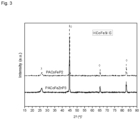
Figure 3 . XRD patterns of PACoFeP2 and PACoFeZnP3 catalysts - All terms as used herein in this application, unless otherwise stated, shall be understood in their ordinary meaning as known in the art. Other more specific definitions for certain terms as used in the present application are as set forth below and are intended to apply throughout the description and claims.
- Where in the present invention a numerical interval is used, this includes the values of the extremes of the interval.
- The terms " weight percent", "vol. percent ", or "mol. percent" refers to a weight, volume, or molar percentage of a component, respectively, based on the total weight, the total volume of material, or total moles, that includes the component. In a non-limiting example, 10 grams of component in 100 grams of the material is 10 weight percent of component. Thus, the term "percentage by weight (% w/w)", when referred to the metal alloy nanoparticles comprised in the composite catalyst, is estimated determining the amount of metal alloy nanoparticles with respect to the total weight of the composite catalyst and the resulting value is multiplied by 100.
- The phrase "water splitting" or any variation of this phrase describes the chemical reaction in which water is separated into oxygen and hydrogen under an electric current.
- The use of the words "a" or "an" when used in conjunction with any of the terms "comprising," "including," "containing," or "having" in the claims, or the specification, may mean "one," but it is also consistent with the meaning of "one or more," "at least one," and "one or more than one."
- The words "comprising" (and any form of comprising, such as "comprise" and "comprises"), "having" (and any form of having, such as "have" and "has"), "including" (and any form of including, such as "includes" and "include") or "containing" (and any form of containing, such as "contains" and "contain") are inclusive or open-ended and do not exclude additional, unrecited elements or method steps; and encompasses the case of "consisting of".
- As mentioned above, the present invention relates to a pyrolyzed composite catalyst, comprising:
- i) electrocatalytically active metal alloy nanoparticles, and
- ii) a nitrogen-doped carbonaceous matrix comprising a nitrogen content in a range from 0.1% to 5%, as a percentage of dry weight based on the total weight of the composite catalyst as measured by elemental analysis;
- wherein the matrix comprises a pyrolysis product of a polyamide material;
- wherein the metal alloy nanoparticles are present in a weight percent in a range from 10 % and 70 % based on the total weight of the composite catalyst.
- In accordance with some embodiments, optionally in combination with any of the embodiments above or below, the electrocatalytically active metal alloy nanoparticles have a particle size in a range from 0.1 nm and 60 nm as determined by High-Resolution Transmission Electron Microscopy (HRTEM).
- In some embodiments, optionally in combination with any of the embodiments above or below, the composite catalyst has a surface area in a range from 80 m2/g and 300 m2/g, preferably from 90 m2/g and 280 m2/g, more preferably from 100 m2/g and 250 m2/g, as determined by Brunauer-Emmett-Teller (BET) method.
- In some embodiments, optionally in combination with any of the embodiments above or below, the nitrogen-doped carbonaceous matrix, have an average pore size in a range from 0.1 nm and 17 nm, preferably from 1 nm and 15 nm, more preferably from 2 nm and 12 nm, as determined by the Barret-Joyner-Halenda (BJH) method.
- As mentioned above, in the pyrolyzed composite material, the metal alloy nanoparticles are present in a weight percent in a range from 10 % and 70 % based on the total weight of the composite catalyst. In accordance with some embodiments, the metal alloy nanoparticles are present in a weight percent in a range from 12% and 60%, preferably from 17% and 40%; even more preferably from 20% and 30%.
- The pyrolyzed composite catalysts according to the present invention comprises i) electrocatalytically active metal alloy nanoparticles, and ii) a nitrogen-doped carbonaceous matrix, wherein the metal alloy nanoparticles are embedded within the carbonaceous matrix. Embedment is accomplished by physical entrapment or/and covalent linking or/and conjugation of the nanoparticles to the carbonaceous matrix. Preferably, the nanoparticles are dispersed in the matrix and are held therein by physical entrapment.
- Some particular embodiments relate to pyrolyzed composite catalysts comprising
- i) electrocatalytically active metal alloy nanoparticles of a particle size between 0.1 nm and 60 nm as determined High-Resolution Transmission Electron Microscopy (HRTEM) and
- ii) a nitrogen-doped carbonaceous matrix;
- wherein the nitrogen-doped carbonaceous matrix is obtainable by pyrolysis of a polyamide material;
- wherein the metal alloy nanoparticles are present in a weight percent between 10 % and 70 % based on the total weight of the composite catalyst, and
- wherein the metal alloy nanoparticles are embedded within the carbonaceous matrix.
- In some embodiments, optionally in combination with any of the embodiments above or below, the metal alloy comprises two or more metals selected from the group consisting of cobalt (Co), iron (Fe), copper (Cu), titanium (Ti), Vanadium (V), chromium (Cr), manganesium (Mn), nickel (Ni), zinc (Zn), iridium (Ir), ruthenium (Ru), osmium (Os), gold (Au), niobium (Nb), molybdenum (Mo), and tungsten (W); preferably two or more metals selected from the group consisting of Co, Fe, Zn, Cu, and Ni; being particularly preferred a metal alloy selected from a Co-Fe alloy, Ni-Fe alloy, Co-Ni alloy, Co-Fe-Zn alloy, Co-Fe-Ni alloy, and Cu-Fe alloy.
- In accordance with some embodiments, optionally in combination with any of the embodiments above or below, the nitrogen-doped carbonaceous matrix contains a nitrogen content ranging from 0.1% to 5%, as a percentage of dry weigh measured by elemental analysis; preferably from 0.2% to 4.8%, more preferably from 0.3% to 3%.
- In accordance with some embodiments, optionally in combination with any of the embodiments above or below, the nitrogen-doped carbonaceous matrix has an average pore size comprised between 0.1 and 17 nm as determined by Barret-Joyner-Halenda (BJH) method.
- As mentioned herein, the nitrogen-doped carbonaceous matrix comprises a pyrolysis product of a polyamide material.
- In some embodiments, optionally in combination with any of the embodiments above or below, the nitrogen-doped carbonaceous matrix comprises graphene flakes and carbon shell structures such as fullerene-like cavities.
- Nitrogen -containing nanostructured carbons have promising catalytic activity for oxygen evolution reactions. However, the methods to prepare N-doped carbon structures containing graphene, carbon shell or fullerene-like carbon normally rely on very harsh processes and multistep procedures, which involve high-temperature production of carbon materials followed by the introduction of N into de carbon structure by using NH3, amines, urea or melamine. Herein, N-doped carbon nanostructures are facilely produced from polyamide materials.
- In some embodiments, optionally in combination with any of the embodiments above or below, the polyamide material, i.e. a polymer material which contains recurring amide groups (R-CO-NH-R') as integral parts of the main polymer chain, may be any known natural or synthetic polyamide material. Examples of suitable polyamide material include aliphatic polyamides such as Nylon 6 (i.e. prepared by ring-opening polymerization of monomer caprolactam), Nylon 66 (i.e. a polyamide that is made of two monomers that is hexamethylenediamine and adipic acid); polyphthalamides such as PA 6T (resulting from reaction of hexamethylenediamine and terephthalic acid), and aromatic polyamides such those resulting from reaction of paraphenylenediamine and terephthalic acid.
- Polyurethane polymers are generally produced by the reaction of a polyisocyanate, particularly diisocyanates, with hydroxyl-rich compounds such as glycols and polyester and polyether polyols. It is of interest to recovery and reuse of polyurethane chemical components in new product manufacture. It is the general purpose of polyurethane chemical recycling to recover the polyol (one of its constituents) which may be used as a valuable raw material to manufacture new polyurethane foams.
- Chemical depolymerisation of polyurethanes may be achieved, amongst other processes, by hydrolysis, hydroglycolysis, aminolysis, glycolysis and acidolysis.
- In the acidolysis process for recycling polyurethane foams, a polyamide subproduct may be recovered in addition to the polyol. The polyamide subproduct may be used as raw material in the preparation of the pyrolyzed composite catalysts of the present invention.
- Thus, in accordance with some embodiments of the present invention, the polyamide material is obtained from a polyurethane material which may be both, a waste polyurethane material or a fresh polyurethane material.
- In the experimental section of the present disclosure, there were used different polyurethane materials as raw materials for the preparation of the polyamides used in the preparation of the pyrolyzed composite catalysts of the invention. Thus, there were used a mixture of waste polyurethane, a polyurethane prepared from TDI (toluendiisocyanate), a polyurethane prepared from MDI (methylene diphenyl diisocyanate), a polyurethane prepared from TDI which has undergone a deamination process to eliminate the TDA (toluene diamine) derived from the isocyanate present in the foam.
- Thus, in accordance with some embodiments, optionally in combination with any of the embodiments above or below, the polyamide material is obtainable from polyurethane foams. Preferably, the polyamide is obtainable by acidolysis of polyurethane materials.
- A second aspect of the present invention relates to a one-step method for preparing a composite catalyst. The method comprising contacting under pyrolytic conditions two or more alloy precursors selected from metal salts and metal complexes, comprising two or more metals selected from the group consisting of Co, Fe, Cu, Ti, V, Cr, Mn, Ni, Zn, Ir, Ru, Os, Au, Nb, Mo, and W; with a polyamide material, wherein the carbonization temperature ranges from 700 to 1000 °C, wherein the pyrolysis temperature increase rate ranges from 1 °C/min to 10 °C/min. The method further comprises a cooling step to room temperature to collect the composite catalyst thus obtained.
- In accordance with some embodiments, optionally in combination with any of the embodiments above or below, the metal alloy precursors are metal salts and metal complexes comprising metals selected from the group consisting of Co, Fe, Cu, Ti, V, Cr, Mn, Ni, Zn, Ir, Ru, Os, Au, Nb, Mo, and W; preferably Co, Fe, Zn, Cu, and Ni; being particularly preferred a metal alloy selected from a Co-Fe alloy, Ni-Fe alloy, Co-Ni alloy, Co-Fe-Zn alloy, Co-Fe-Ni alloy, Cu-Fe alloy.
- In some particular embodiments, optionally in combination with any of the embodiments above or below, the metal alloy precursors are metal salts and metal complexes selected from CoCl2, FeCl3, ZnCl2, CuCl2, NiCl2.
- In accordance with some embodiments, optionally in combination with any of the embodiments above or below, the method comprises contacting under pyrolytic conditions a mixture of two metal alloy precursors at an atomic metal ratio ranging from 4:1 to 1:4, preferably from 3:1 to 1:3, more preferably 1:1 of the metal alloy precursors.
- In some particular embodiments, optionally in combination with any of the embodiments above or below, the method comprises contacting under pyrolytic conditions a mixture of three metal alloy precursors. Thus, when the metal alloy comprises three metal atoms, according to the formula
(AxBy)nCz
- being A, B and C the different metal atoms;
- wherein the ratio between x to y ranges from 4:1 to 1:4, preferably from 3:1 to 1:3, more preferably from 1:1; and
- the ratio between n to z ranges from 1:2 to 10:1, preferably from 1:1 to 5:1
- In accordance with some particular embodiments, optionally in combination with any of the embodiments above or below, the method comprises contacting under pyrolytic conditions a mixture at a metal precursor and a polyamide material at a weight-weight ratio from 3:1 to 1:3, more preferably 1:1.
- In some embodiments, optionally in combination with any of the embodiments above or below, the polyamide material contains a nitrogen content ranging from 2% to 20% by weight, as measured by elemental analyst, preferably from 5% to 15%, more preferably from 6% to 12%.
- In some embodiments, optionally in combination with any of the embodiments above or below, the polyamide is obtainable from polyurethane foams. Thus, in some embodiments, the polyamide is obtainable by acidolysis of polyurethane materials.
- In some embodiments, optionally in combination with any of the embodiments above or below, the acidolysis procedure comprises contacting the polyurethane material with an acid solution, preferably from an organic acid; more preferably at least one dicarboxylic acid or at least one carboxylic acid derivative (such as succinic acid, succinic anhydride, phthalic anhydride, phthalic acid, maleic anhydride, adipic acid, and glutaric acid); preferably in the presence of at least one polyether polyol and at least one radical generator (such as methyl ethyl ketone peroxide, cumene hydroperoxide, di-tert-butyl peroxide, or ethylbenzene hydroperoxide) suitable for initiating radical polymerization and a carbon unsaturated monomer containing carbonyl groups be subjected to the grafting reaction, and allowing at least a portion of the polyurethane material to decompose into a recovered raw material composition comprising a polyamide compound.
- In some embodiments, optionally in combination with any of the embodiments above or below, the carbonization temperature ranges from 700°C to 1000°C, preferably from 720°C to 960°C, more preferably from 800°C to 920°C; being particularly preferred a carbonization temperature of 900°C; and wherein the pyrolysis temperature increase rate ranges from 1°C/min to 10°C/min, preferably from 2°C/min to 5°C/min, being particularly preferably 3.3°C/min up to 900°C.
- An additional aspect of the present invention relates to a composite catalyst obtainable by the one-step method as described hereinabove.
- In a further aspect, the present invention provides a method for producing an electrode comprising the steps of:
- a) preparing a composite catalyst according to the one-step method described herein;
- b) supporting the composite catalyst obtained in a) on an electrically conductive substrate or on polymeric membrane.
- Suitable support materials are commercially available or can be produced using conventional methods known to the person skilled in the art. Thus, in accordance with some embodiments, optionally in combination with any of the embodiments above or below, the electrically conductive substrate is selected from glass carbon, paper carbon, cloth carbon, anion exchange membrane. Alternatively, in some other embodiments, optionally in combination with any of the embodiments above or below, the support material is an ion exchange membrane.
- The skilled person knows suitable methods of supporting the composite catalyst on the electrically conductive substrate or on an ion exchange membrane. In some embodiments, optionally in combination with any of the embodiments above or below, the supporting step comprises the addition of an appropriate amount of ink, which contains a dispersion of catalyst into a solvent and an ionomer.
- In some embodiments, optionally in combination with any of the embodiments above or below, there is provided a water electrolyzer, comprising: an electrolytic cell which comprises an electrolyte, the electrolyte being in the form of an electrolyte aqueous solution or alternatively in the form of a polymeric membrane; a first electrode (anode) comprising the electrocatalyst as herein or as manufactured by the process as defined herein; a second electrode (cathode); and a voltage source to provide a current density to cause the water to be electrochemically split to form oxygen and hydrogen at the anode and cathode respectively. The first electrode and the second electrode being electrically connected to the power supply. The water electrolyzer can include one or more operating features, elements, or conditions and/or includes equipment or features thereof having one or more features, as described or illustrated or claimed herein. In an exemplary embodiment, in the water electrolyzer, an ion exchange unit may be further disposed between the first electrode and the second electrode.
- Each of the first electrode and the second electrode may be formed of a semiconductor or conductive material. The composite catalyst is disposed on the at least one side of the first electrode.
- The electrolyte aqueous solution may serve as a supply source of water, used for a water decomposition reaction. The electrolyte aqueous solution may include, for example 0.1M-1M NaOH. A pH of the electrolyte aqueous solution may be between 12-14.
- When the voltage is applied between the first electrode and the second electrode in the water decomposition system, a reaction, in which oxygen is generated in the first electrode comprising the composite catalyst, and hydrogen is generated in the second electrode, may occur.
- In some embodiments, optionally in combination with any of the embodiments above or below, there is provided a system for CO and/or CO2 electroreduction to produce a multi-carbon compound, comprising: an electrolytic cell configured to receive a liquid electrolyte and CO and/or CO2 gas; an anode comprising the electrocatalyst as defined herein or as manufactured by the process as defined herein; a cathode comprising a copper containing electroreduction catalyst; and a voltage source to provide a current density to cause the CO and/or CO2 gas contacting the cathode to be electrochemically converted into the multi-carbon compound and to cause an oxygen evolution reaction at the anode. The system can also include one or more operating features, elements, or conditions and/or includes equipment or features thereof having one or more features, as described or illustrated or claimed herein.
- The composite catalyst of the present invention may be used as an oxygen evolution catalyst having improved catalyst characteristics under basic conditions.
- As mentioned above, an aspect of the present invention relates to an electrochemical device comprising the electrode as defined in the claims. In accordance with some particular embodiments, the electrochemical device is a water electrolyzer for the electrolytic splitting of water into hydrogen and/or oxygen, wherein the device comprises:
- an electrode as defined hereinabove;
- a container for holding an electrolyte;
- a counter electrode; and
- a power source configured to apply a voltage across the electrodes.
- Throughout the description and claims the word "comprise" and variations of the word, are not intended to exclude other technical features, additives, components, or steps. Additional objects, advantages and features of the invention will become apparent to those skilled in the art upon examination of the description or may be learned by practice of the invention. Although only a number of examples have been disclosed herein, other alternatives, modifications, uses and/or equivalents thereof are possible. Furthermore, all possible combinations of the described examples are also covered. Thus, the scope of the present disclosure should not be limited by particular examples but should be determined only by a fair reading of the claims that follow.
- The following examples and drawings are provided by way of illustration, and they are not intended to be limiting of the present invention. Furthermore, the present invention covers all possible combinations of particular and preferred embodiments described herein.
- Polyurethane foam acidolysis was performed following the procedure described in
DE19512778 C1 . -
DE19512778C1 disclose preparing a reaction mixture comprising a dicarboxylic acid or a derivative thereof, a polyether polyol with functionality of 3, a radical generator and a carbon unsaturated monomer containing carbonyl groups be subjected to the grafting reaction; adding a polyurethane waste and reacting the resulting mixture at a temperature between 140°C and 250°C (preferably 170°C-220°C) reaction times of 1 to 10 hours being required to form a dispersion. Optionally the polyol dispersion can be deaminized by glycidyl ethers reaction. - It was obtained a dispersion containing polyamide particles in a liquid polyol. The polyamide solid particles (PA) were separated by centrifugation from the liquid phase.
- Table 1 shows the nitrogen content, as a percentage of dry weigh measured by elemental analysis based on the total weight of the polyamide.
Table 1 Polyamide N % wt PATDI 11 PATDIdes 11 PAMDI 7 PAS 12 - In a mortar, the polyamide together with the corresponding metal salts (ratio polyamide:metal of 1:1) were ground until a homogeneous mixture was obtained. The mixture was pyrolyzed at high temperatures (1000°C, 900°C, 800°C), where it was kept for 1 or 2 hours under N2. Temperature ramp was also performed by stopping at 500°C for 30 min and increasing up to 900°C for 1h. The pyrolysis temperature increase rate was 3.3 °C/min in all samples.
Table 2. Catalysis synthesis details Cod. Composite catalyst Polyamide Alloy precursors Temperature (°C) Yield (%) IrO2 - PACoFeP1 PATDI CoCl2·6H2O 500 and 900 34 FeCl3·6H2O PACoFeP2 PATDI CoCl2·6H2O 900 33 FeCl3·6H2O PACoFeZnP3 PATDI CoCl2·6H2O 1000 34 FeCl3·6H2O ZnCl2 PASCoFeP1 PAS CoCl2·6H2O 500 and 900 41 FeCl3·6H2O PASCoFeP2 PAS CoCl2·6H2O 900 40 FeCl3·6H2O PATDIdesCoFeP1 PATDIdes CoCl2·6H2O 500 and 900 36 FeCl3·6H2O PATDIdesCoFeP2 PATDIdes CoCl2·6H2O 900 35 FeCl3·6H2O PANyCoFeP2 PANy CoCl2·6H2O 900 26 FeCl3·6H2O PAMDICoFeP1 PAMDI CoCl2·6H2O 500 and 900 33 FeCl3·6H2O PAMDICoFeP2 PAMDI CoCl2·6H2O 900 32 FeCl3·6H2O PA12CoFeP2 PA12 CoCl2·6H2O 900 17 FeCl3·6H2O PANomCoFeP2 PANom CoCl2·6H2O 900 38 FeCl3·6H2O - PATDI is the polyamide as obtained in Example 1, from TDI polyurethane foams
- PAS is a synthetic polyamide obtained by an equimolar reaction of toluenediamine (TDA) with dicarboxylic acids
- PAMDI is a polyamide obtained by acidolysis of MDI polyurethane foams
- PATDIdes is a polyamide obtained by acidolysis of TDI polyurethane foams which has undergone a deamination process in order to eliminate the TDA
- PANy is a commercial polyamide,
Nylon - PA12 is a commercial polyamide,
polyamide 12, obtained from MERCK - PANom is a commercial polyamide, Nomex, obtained from MERCK
- Electrochemical characterization was performed in a conventional three-electrode electrochemical cell coupled to an Autolab PGSTAT302 potentiostat. The catalysts were analyzed in the oxygen evolution reaction (OER) using as working electrode a rotating ring disk electrode (RRDE) where the dye prepared with the catalyst is deposited, as counter electrode glassy carbon and as reference electrode a reversible hydrogen electrode (RHE).
- The ink catalyst solution was prepared by sonicating some catalyst powder in ethanol to obtain a concentration of 10 mg·mL-1 and 5 wt.% of Nafion solution. A quantity of 20 µL of catalytic ink was deposited in a glassy carbon disc (5 mm diameter, 0.196 cm2) of a rotating ring disc electrode (RRDE) to prepare the working electrode (WE).
- The measurements were carried out using NaOH 0.1M or 1M as supporting electrolyte and saturating the solution with Ar. For the OER measurements, the electrode was rotated at 1600 rpm and a cyclic voltammetry between 1.1 and 1.8 V at a sweep speed of 5 mV/s was recorded. The ring was held at a controlled potential of 0.4 V to detect oxygen formation and differentiate it from oxide formation on the catalyst.
- IrO2 catalyst was used as reference, having an overpotential (η) of 0.399V at a current density of 10 mA/cm2:

- Tafel slope was calculated which allows us to obtain a direct correlation between the current changes and the applied potential (Table 2). A lower value of the Tafel slope indicates a faster increase of the catalytic current when a higher potential is applied. Values between 54-69 mV/dec have been obtained, lower even than that of IrO2 (70 mV/Dec).
Table 3. Values of overpotential (η) and Tafel slope of the catalysts Cod. Composite catalyst η (mV) at 0.1M NaOH Tafel (mV/dec) IrO2 399 70 PACoFeP1 (PATDI) 410 62 PACoFeP2 (PATDI) 370 58 PACoFeZnP3 (PATDI) 410 64 PASCoFeP1 410 61 PASCoFeP2 440 69 PATDIdesCoFeP1 420 61 PATDIdesCoFeP2 440 68 PANyCoFeP2 400 54 PAMDICoFeP1 410 66 PAMDICoFeP2 420 65 PA12CoFeP2 400 63 PANomCoFeP2 400 60 - Stability measurements were carried at NaOH 0.1M out using chronopotentiometry for PACoFeP2 and PACoFeZnP3 catalysts by maintaining a current density of 10 mA/cm2 for 18 hours and registering the evolution of the potential. Results are shown in
Figure 1 . - In addition, PACoFeP2 and PACoFeZnP3 were analyzed using NaOH 1M as electrolyte. In this case it was observed that both catalysts give rise to overpotentials lower than that of iridium oxide with this electrolyte (Table 4 and
Figure 2 )Tabla 4. Values of overpotential at NaOH 1MCod. Composite catalyst η* (mV) IrO2 350 PACoFeP2 340 PACoFeZnP3 330 - The composite catalysts samples were characterized using X-ray diffraction (XRD), in a in X'Pert Pro PAN-analytical diffractometer. XRD diffractograms obtained by studying the different crystalline phases of the catalysts by XRD where the presence of a graphite-like structure and a CoFe alloy was detected in all cases (
Figure 3 ). - The composite catalysts were also analyzed by transmission electron microscopy (TEM), in a JEOL JEM 2100. The images obtained by TEM showed that metallic alloy particles are embedded in a nitrogen-doped carbonaceous matrix, with some parts with graphene flakes and carbon shells structures such as fullerene-like cavities.
- The BET specific area values and chemical composition are shown in Table 5. The composites display type IV isotherms, which is typical of mesoporous materials. They have BET specific areas ranging from 84 to 287 m2/g, depending on the starting polymer used. The pore size distribution of these composites shows the formation of mesoporous with an average pore size of 4 nm.
Table 5. BET specific area values, average pore size and chemical composition. Cod. Composite catalyst BET (m2/g) Average Pore size (nm) N (wt.%) Co/Fe (wt.%) PACoFeP2 104 3 0.4 16/13 PACoFeZn3 90 0.35 16/12 PASCoFeP1 132 4 0.7 12/12 PATDIdesCoFeP1 125 4 0.64 14/11 PAMD!CoFeP1 287 4 1.369 13/12 -
Claims (15)
- A pyrolyzed composite catalyst, comprisingi) electrocatalytically active metal alloy nanoparticles, andii) a nitrogen-doped carbonaceous matrix comprising a nitrogen content in a range from 0.1% to 5%, as a percentage of dry weight based on the total weight of the pyrolyzed composite catalyst as measured by elemental analysis;wherein the matrix comprises a pyrolysis product of a polyamide material;wherein the metal alloy nanoparticles are present in a weight percent in a range from 10 % and 70 % based on the total weight of the composite catalyst.
- The pyrolyzed composite catalyst according to claim 1, wherein the electrocatalytically active metal alloy nanoparticles have a particle size in a range from 0.1 nm and 60 nm as determined by High-Resolution Transmission Electron Microscopy (HRTEM).
- The pyrolyzed composite catalyst according to any of claims 1-2, wherein the composite catalyst has a surface area in a range from 80 m2/g and 300 m2/g as determined by Brunauer-Emmett-Teller (BET) method.
- The pyrolyzed composite catalyst according to any of claims 1-3, wherein the nitrogen-doped carbonaceous matrix, have an average pore size in a range from 0.1 nm and 17 nm as determined by the standard Barret-Joyner-Halenda (BJH) method.
- The pyrolyzed composite catalyst according to any of claims 1-4, wherein the metal alloy comprises two or more metals selected from the group consisting of Co, Fe, Ti, V, Cr, Mn, Ni, Zn, Ir, Ru, Os, Au, Nb, Mo, and W.
- The pyrolyzed composite catalyst according to any of the claims 1-5, wherein the nitrogen-doped carbonaceous matrix comprises graphene flakes and fullerene-like cavities.
- The pyrolyzed composite catalyst according to any of the claims 1-6, which comprisesi) electrocatalytically active metal alloy nanoparticles of a particle size between 0.1 nm and 60 nm as determined by High-Resolution Transmission Electron Microscopy (HRTEM) andii) a nitrogen-doped carbonaceous matrix;wherein the nitrogen-doped carbonaceous matrix is obtainable by pyrolysis of a polyamide material;wherein the metal alloy nanoparticles are present in a weight percent between 10 % and 70 % based on the total weight of the composite catalyst, andwherein the metal alloy nanoparticles are embedded within the carbonaceous matrix.
- A one-step method for preparing a pyrolyzed composite catalyst comprising contacting under pyrolytic conditions two or more alloy precursors selected from metal salts and metal complexes, comprising two or more metals selected from the group consisting of Co, Fe, Cu, Ti, V, Cr, Mn, Ni, Zn, Ir, Ru, Os, Au, Nb, Mo,and W; with a polyamide material, wherein the pyrolysis temperature ranges from 700 to 1000 °C, wherein the pyrolysis temperature increase rate ranges from 1 - 10°C/min.
- The one-step method according to claim 8, wherein the polyamide material is obtained by acidolysis of a polyurethane foam.
- A pyrolyzed composite catalyst obtainable by the process according to any of claims 8-9.
- An electrode comprising the pyrolyzed composite catalyst according to any one of claims 1 to 7.
- The electrode according to claim 11, wherein the pyrolyzed composite catalyst is supported on an electrically conductive substrate or on an ion exchange membrane forming a MEA (membrane electrode assembly) or CCM (catalyst coated membrane).
- Use of the pyrolyzed composite catalyst as defined in any of claims 1 to 7, as an anode catalyst for the electrolytic oxygen evolution reaction in an electrochemical device.
- An electrochemical device comprising the electrode as defined in any of claims 11-12.
- The electrochemical device of claim 14, wherein the device is a water electrolyzer for the electrolytic splitting of water into hydrogen and/or oxygen, wherein the device comprises:- an electrode as defined in any of claims 11-12;- a container for holding an electrolyte;- a counter electrode; and- a power source configured to apply a voltage across the electrodes.
Priority Applications (2)
| Application Number | Priority Date | Filing Date | Title |
|---|---|---|---|
| EP23383098.3A EP4545684A1 (en) | 2023-10-26 | 2023-10-26 | Pyrolyzed composite catalysts |
| PCT/EP2024/080166 WO2025088084A1 (en) | 2023-10-26 | 2024-10-25 | Pyrolyzed composite catalysts |
Applications Claiming Priority (1)
| Application Number | Priority Date | Filing Date | Title |
|---|---|---|---|
| EP23383098.3A EP4545684A1 (en) | 2023-10-26 | 2023-10-26 | Pyrolyzed composite catalysts |
Publications (1)
| Publication Number | Publication Date |
|---|---|
| EP4545684A1 true EP4545684A1 (en) | 2025-04-30 |
Family
ID=88598808
Family Applications (1)
| Application Number | Title | Priority Date | Filing Date |
|---|---|---|---|
| EP23383098.3A Withdrawn EP4545684A1 (en) | 2023-10-26 | 2023-10-26 | Pyrolyzed composite catalysts |
Country Status (2)
| Country | Link |
|---|---|
| EP (1) | EP4545684A1 (en) |
| WO (1) | WO2025088084A1 (en) |
Citations (2)
| Publication number | Priority date | Publication date | Assignee | Title |
|---|---|---|---|---|
| DE19512778C1 (en) | 1995-04-05 | 1996-12-05 | Gunter Prof Dr Bauer | Prodn. of isocyanate-reactive poly:ol dispersion from waste polyurethane |
| WO2022264112A1 (en) * | 2021-06-17 | 2022-12-22 | King Abdullah University Of Science And Technology | Catalysts for ammonia synthesis |
-
2023
- 2023-10-26 EP EP23383098.3A patent/EP4545684A1/en not_active Withdrawn
-
2024
- 2024-10-25 WO PCT/EP2024/080166 patent/WO2025088084A1/en active Pending
Patent Citations (2)
| Publication number | Priority date | Publication date | Assignee | Title |
|---|---|---|---|---|
| DE19512778C1 (en) | 1995-04-05 | 1996-12-05 | Gunter Prof Dr Bauer | Prodn. of isocyanate-reactive poly:ol dispersion from waste polyurethane |
| WO2022264112A1 (en) * | 2021-06-17 | 2022-12-22 | King Abdullah University Of Science And Technology | Catalysts for ammonia synthesis |
Non-Patent Citations (2)
| Title |
|---|
| LI AIQIN ET AL: "Highly selective hydrogenation of phenol to cyclohexanol over MOF-derived non-noble Co-Ni@NC catalysts", CHEMICAL ENGINEERING SCIENCE, OXFORD, GB, vol. 166, 11 March 2017 (2017-03-11), pages 66 - 76, XP085000650, ISSN: 0009-2509, DOI: 10.1016/J.CES.2017.03.027 * |
| SÁNCHEZ-SÁNCHEZ A ET AL: "Evolution of the complex surface chemistry in mesoporous carbons obtained from polyaramide precursors", APPLIED SURFACE SCIENCE, ELSEVIER, AMSTERDAM , NL, vol. 299, 5 February 2014 (2014-02-05), pages 19 - 28, XP028631098, ISSN: 0169-4332, DOI: 10.1016/J.APSUSC.2014.01.171 * |
Also Published As
| Publication number | Publication date |
|---|---|
| WO2025088084A1 (en) | 2025-05-01 |
Similar Documents
| Publication | Publication Date | Title |
|---|---|---|
| Gebreslase et al. | Transformation of CoFe2O4 spinel structure into active and robust CoFe alloy/N-doped carbon electrocatalyst for oxygen evolution reaction | |
| Ramos-Sánchez et al. | PdNi electrocatalyst for oxygen reduction in acid media | |
| KR102580737B1 (en) | METHOD OF MANUFACTURING NiCoFe LAYERED DOUBLE HYDROXIDE, ELECTRODE, MEMBRANE ELECTRODE ASSEMBLY AND WATER ELECTROYSISING SYSTEM COMPRISING THE SAME | |
| Ghasemi et al. | Introducing an affordable catalyst for biohydrogen production in microbial electrolysis cells | |
| US10669640B2 (en) | Ultral-low loading of Pt-decorated Ni electrocatalyst, manufacturing method of the same and anion exchange membrane water electrolyzer using the same | |
| Moazzami et al. | Enhanced methanol electrooxidation by electroactivated Pd/Ni (OH) 2/N-rGO catalyst | |
| Yang et al. | PdBi bimetallic catalysts including polyvinylpyrrolidone surfactant inducing excellent formic acid oxidation reaction and direct formic acid fuel cell performance | |
| EP2562860B1 (en) | Carbon catalyst for direct fuel cell cathode, and direct fuel cell cathode and direct fuel cell using same | |
| Chen et al. | Self-adhesive ionomers for durable low-temperature anion exchange membrane electrolysis | |
| CN110711583B (en) | A kind of high-efficiency electrocatalyst material with three-dimensional structure, preparation method and application thereof | |
| CN105780050B (en) | A kind of preparation method for decomposing the doping phosphoric acid group Ni-Fe hydroxide nano film catalysts of water | |
| Xing et al. | Efficient bicarbonate electrolysis to formate enabled via ionomer surface modification in cation exchange membrane electrolyzers | |
| Zhang et al. | Bifunctional nanoporous Ni-Zn electrocatalysts with super-aerophobic surface for high-performance hydrazine-assisted hydrogen production | |
| WO2021219220A1 (en) | (bi)metal sulfide polymer composite material, and its use as catalyst for hydrogen production | |
| Cabot et al. | Advanced Supports for Noble Metal Catalysts in Proton Exchange Membrane Water Electrolysers: A Review: Improving the performance, stability, durability and cost of iridium-and platinum-based catalytic materials | |
| Park et al. | Crusty-structured Cu@ NiCo nanoparticles as anode catalysts in alkaline fuel cells | |
| Ma et al. | Manganese, iron co-doped Ni2P nanoflowers as a powerful electrocatalyst for oxygen evolution reaction | |
| Cai et al. | Two-dimensionally confined Ir/WO x heterointerfaces boost the acidic oxygen evolution reaction for ampere-level stable PEM water electrolysis | |
| US20240352602A1 (en) | A catalyst | |
| Niyitanga et al. | Time-dependent oxidation of graphite and cobalt oxide nanoparticles as electrocatalysts for the oxygen evolution reaction | |
| WO2025088084A1 (en) | Pyrolyzed composite catalysts | |
| Cardoso et al. | Palladium-nickel on tin oxide-carbon composite supports for electrocatalytic hydrogen evolution | |
| KR102808581B1 (en) | electrocatalyst for water splitting and manufacturing method thereof | |
| Kim et al. | The development of a gas-feeding CO2 fuel cell using direct hydrazine oxidation reaction | |
| Asai et al. | Electronic structure control of IrO2 via conjugated polymer support for highly efficient oxygen evolution reaction |
Legal Events
| Date | Code | Title | Description |
|---|---|---|---|
| PUAI | Public reference made under article 153(3) epc to a published international application that has entered the european phase |
Free format text: ORIGINAL CODE: 0009012 |
|
| STAA | Information on the status of an ep patent application or granted ep patent |
Free format text: STATUS: THE APPLICATION HAS BEEN PUBLISHED |
|
| AK | Designated contracting states |
Kind code of ref document: A1 Designated state(s): AL AT BE BG CH CY CZ DE DK EE ES FI FR GB GR HR HU IE IS IT LI LT LU LV MC ME MK MT NL NO PL PT RO RS SE SI SK SM TR |
|
| STAA | Information on the status of an ep patent application or granted ep patent |
Free format text: STATUS: THE APPLICATION IS DEEMED TO BE WITHDRAWN |
|
| 18D | Application deemed to be withdrawn |
Effective date: 20251031 |