EP4545661A1 - Sintering process control method, operation guidance method, sintered ore manufacturing method, sintering process control device, operation guidance device, sintering operation guidance system, and terminal device - Google Patents
Sintering process control method, operation guidance method, sintered ore manufacturing method, sintering process control device, operation guidance device, sintering operation guidance system, and terminal device Download PDFInfo
- Publication number
- EP4545661A1 EP4545661A1 EP23863106.3A EP23863106A EP4545661A1 EP 4545661 A1 EP4545661 A1 EP 4545661A1 EP 23863106 A EP23863106 A EP 23863106A EP 4545661 A1 EP4545661 A1 EP 4545661A1
- Authority
- EP
- European Patent Office
- Prior art keywords
- operation amount
- sintering process
- sintering
- predicted value
- guidance
- Prior art date
- Legal status (The legal status is an assumption and is not a legal conclusion. Google has not performed a legal analysis and makes no representation as to the accuracy of the status listed.)
- Pending
Links
Images





Classifications
-
- C—CHEMISTRY; METALLURGY
- C22—METALLURGY; FERROUS OR NON-FERROUS ALLOYS; TREATMENT OF ALLOYS OR NON-FERROUS METALS
- C22B—PRODUCTION AND REFINING OF METALS; PRETREATMENT OF RAW MATERIALS
- C22B1/00—Preliminary treatment of ores or scrap
- C22B1/14—Agglomerating; Briquetting; Binding; Granulating
- C22B1/16—Sintering; Agglomerating
- C22B1/20—Sintering; Agglomerating in sintering machines with movable grates
- C22B1/205—Sintering; Agglomerating in sintering machines with movable grates regulation of the sintering process
-
- C—CHEMISTRY; METALLURGY
- C22—METALLURGY; FERROUS OR NON-FERROUS ALLOYS; TREATMENT OF ALLOYS OR NON-FERROUS METALS
- C22B—PRODUCTION AND REFINING OF METALS; PRETREATMENT OF RAW MATERIALS
- C22B1/00—Preliminary treatment of ores or scrap
- C22B1/14—Agglomerating; Briquetting; Binding; Granulating
- C22B1/16—Sintering; Agglomerating
- C22B1/20—Sintering; Agglomerating in sintering machines with movable grates
-
- C—CHEMISTRY; METALLURGY
- C22—METALLURGY; FERROUS OR NON-FERROUS ALLOYS; TREATMENT OF ALLOYS OR NON-FERROUS METALS
- C22B—PRODUCTION AND REFINING OF METALS; PRETREATMENT OF RAW MATERIALS
- C22B1/00—Preliminary treatment of ores or scrap
- C22B1/14—Agglomerating; Briquetting; Binding; Granulating
- C22B1/16—Sintering; Agglomerating
Definitions
- the present disclosure relates to a method of controlling a sintering process, an operation guidance method, a method of producing sintered ore, a sintering process control unit, an operation guidance apparatus, a sintering operation guidance system, and a terminal apparatus.
- FIG. 1 is a diagram illustrating an overview of the sintering process.
- fine ore, coke breeze, limestone, quicklime, and the like are mixed and granulated into a sintering raw material (quasiparticles) via a surge hopper.
- the sintering raw material is melted by the heat of combustion of coke breeze in the sintering machine. Quasiparticles are then fused to each other, cooled by air drawn from the top, and discharged.
- the heat pattern during this series of heating and cooling processes has a significant impact on product yield.
- the heat pattern is the temperature distribution of the sintering raw material in the longitudinal and thickness directions of the sintering machine.
- the Burn Rising Point (BRP) and Burn Through Point (BTP) are known as feature values of the heat pattern that can be measured.
- the BRP is the position in the longitudinal direction where the exhaust gas temperature in the wind box at the bottom of the sintering machine exceeds a threshold.
- the BTP is the position in the longitudinal direction where the temperature of the exhaust gas measured at the wind box at the bottom of the sintering machine is the highest.
- Patent Literature (PTL) 1 and PTL 2 disclose methods to control the position of the BTP to be constant.
- the control in PTL 1 and 2 performs feedback control based on actual measured values.
- a time delay of about 30 to 40 minutes exists between when raw material is charged into and discharged from the sintering machine. Therefore, with conventional feedback control, the control accuracy may deteriorate due to the inherent time delay in the process.
- a method of controlling a sintering process, an operation guidance method, a method of producing sintered ore, a sintering process control unit, an operation guidance apparatus, a sintering operation guidance system, and a terminal apparatus that can present appropriate operation actions that take into account the time delay of a process can be provided.
- a method of controlling a sintering process, an operation guidance method, a method of producing sintered ore, a sintering process control unit, an operation guidance apparatus, a sintering operation guidance system, and a terminal apparatus will be described below with reference to the drawings.
- the BRP and the BTP are examples of feature values of a heat pattern.
- the BRP is used as an index of the heat pattern in the present embodiment, and a control method to keep this index constant is described.
- the method of controlling a sintering process according to the present embodiment uses a physical model of a sintering machine to predict the heat pattern with high accuracy and to determine the operation amounts of manipulated variables, such as the bed gas flow rate, so that the future BRP is maintained near a target value.
- the BTP can also be used as an index of the heat pattern by replacing the BRP with the BTP in the description below.
- the physical model used in the present disclosure is the same as the model of the method described in the reference Yamaoka et al., ISIJ International, Vol. 45, No. 4, pp. 522 . That is, the physical model consists of a set of partial differential equations that take into account the physical phenomena of combustion of coke breeze, thermal decomposition of limestone, and evaporation of moisture, and that can calculate the state inside the sintering machine.
- this physical model is a two-dimensional non-steady state model that can calculate the state of the sintering process, including the temperature distribution (heat pattern) of sintering raw material in the longitudinal direction and thickness direction in the sintering machine.
- the BRP can also be known from the calculated heat pattern.
- the main input variables that vary with time are the pallet speed, exhaust gas flow rate, raw material bulk density, raw material water content, raw material limestone ratio, and raw material coke ratio.
- These input variables can be the manipulated variables or manipulation factors of the sintering machine.
- direct operation may be difficult depending on the type of exhaust gas flow rate.
- the pallet speed is the speed at which the pallet of the sintering machine on which the sintering raw material is placed moves.
- the exhaust gas flow rate is the flow rate per unit time of the exhaust gas from the sintering machine and can be regulated by an exhaust fan, for example.
- the raw material bulk density is the bulk density of the sintering raw material as calculated from the layer thickness, sintering machine width, and the like.
- the raw material water content, raw material limestone ratio, and raw material coke ratio are the ratios of water, limestone, and coke, respectively, in the sintering raw material.
- Coke is the main agglomeration agent, and the raw material coke ratio is also referred to as the agglomeration agent ratio.
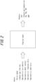
- the main output variables of the physical model are the BTP, the exhaust gas composition, and the BRP.
- the exhaust gas composition includes the ratios of O 2 , CO 2 , and CO.
- the output variables, which change from moment to moment, are calculated using the physical model.
- the time interval for this calculation (the time difference between "t + 1" and "t" in the physical model equations described below) is not particularly limited, but may be one minute as an example.
- u(t) represents the aforementioned input variables, which can be manipulated by the operator of the sintering machine
- x(t) represents state variables calculated in the physical model.
- the state variables are, for example, the heat pattern in the sintering machine, the coke reaction rate, and the gas fractions of CO, CO 2 , and the like.
- y(t) is the aforementioned output variables, such as the BTP, the O 2 ratio in the exhaust gas composition, the CO 2 ratio, the BRP, and the like.
- y(t) includes at least the BRP.
- the output variables of y(t) such as the BTP, the exhaust gas composition, and the BRP, are also referred to as control variables. Control variables are variables that should be controlled during operation, but which are difficult or impossible to manipulate directly and are thus changed via correlated manipulated variables.
- a model predictive control system is constructed to control the BRP using the physical model in Expressions (1) and (2).
- the detailed configuration of the model predictive control system (control unit) is described below, whereas the processing is described here.
- the future BRP is predicted first assuming that the current input variables hold in the future.
- the response y f (t) determined in this way is called the free response.
- the predicted value in the free response is also referred to as the "first predicted value”.
- FIG. 3 is a diagram illustrating predicted values of the BRP.
- the BRP is indicated by the distance [m] from the surge hopper position in the movement direction of the pallet.
- the free response is indicated as a solid line ("no action" in FIG. 3 ).
- the predicted value when a portion of the manipulated variables is changed is also referred to as the "second predicted value".
- the pallet speed was changed (increased) by ⁇ PS 0 .
- the predicted values of the BRP in this case are illustrated by the dashed line ("pallet speed increase" in FIG. 3 ).
- FIG. 4 is a diagram illustrating the step response of the BRP when the pallet speed is increased by a unit amount.
- S PS (k
- the predicted value yielded by changing a portion of the manipulated variables is also determined when determining the predicted value of the free response of the BRP, and the step response is calculated from the difference of these predicted values.
- the manipulated variable to be changed is the palette speed, but other manipulated variables may be changed.
- the bed gas flow rate is one specific example of the exhaust gas flow rate and is the flow rate of exhaust gas in the lower portion of the sintering bed.
- FIG. 5 is a diagram illustrating predicted values of the BRP.
- the free response is indicated as a solid line ("no action" in FIG. 5 ).
- the bed gas flow rate was changed (increased) by ⁇ v 0 .
- the predicted values of the BRP in this case are illustrated by the dashed line ("air flow rate increase" in FIG. 5 ).
- FIG. 6 is a diagram illustrating the step response of the BRP when the bed gas flow rate is increased by a unit amount.
- the step response of the BRP is obtained as illustrated in FIG. 6 .
- the evaluation function J is used to determine the operation amounts of the manipulated variables, for which the step response was determined, so as to reduce the deviation between the predicted value and target value of the BRP. For example, in a case in which the step response of the BRP when the pallet speed and bed gas flow rate are increased by a unit amount is determined, the operation amount of the pallet speed ( ⁇ PS) and the operation amount of the bed gas flow rate ( ⁇ v) are determined using the evaluation function J.
- the evaluation function J can be Expression (5) below, for example.
- the operation amount of the pallet speed ( ⁇ PS) and the operation amount of the bed gas flow rate ( ⁇ v) are determined so as to minimize the evaluation function J in Expression (5).
- y ref is the target value of the BRP
- y pre is the predicted value of the BRP.
- the future BRP can be approximated by superimposing the response y f (t), which is the free response, and the step response.
- y pre (superimposed predicted value)
- y pre (superimposed predicted value)
- y pre t 0 + k y f t 0 + k + S PS k t 0 ⁇ ⁇ PS + S v k t 0 ⁇ ⁇ v
- a portion of the manipulated variables for which a step response is obtained in a case in which the manipulated variables are changed by a unit amount are referred to as "specified manipulated variables".
- the terms in Expressions (5) and (6) for the operation amounts ( ⁇ PS and ⁇ v) can be increased or decreased depending on the specified manipulated variables. For example, in a case of further determining the step response of the BRP (S CR (k
- the term “+c( ⁇ CR) 2 " is added to Expression (5) with c as a weighting factor, and the term “+S CR (k
- a term for the operation amount ( ⁇ WR) of the raw material water content is added.
- the term “+d( ⁇ WR) 2 " is added to Expression (5) with d as a weighting factor, and the term “+S WR (k
- the term “+a( ⁇ PS) 2 " may be excluded from Expression (5), or a may be set to 0, and the term “+Sps(k
- Expression (6) is a linear expression for the operation amounts ( ⁇ PS and ⁇ v) of the specified manipulated variables, which are unknown variables, and the evaluation function J is a quadratic expression for the unknown variables. Therefore, ⁇ PS and ⁇ v can be determined by quadratic programming.
- the specified manipulated variables are the pallet speed and the bed gas flow rate
- the specified manipulated variables are not limited to these.
- the specified manipulated variables may include at least one of the pallet speed, bed gas flow rate, agglomeration agent ratio (raw material coke ratio), and raw material water content, or other variables may be used.
- the evaluation function J may be designed so that the minimization of the deviation between the predicted value and target value of the BRP and the minimization of the operation amounts of the unknown variables correspond to the maximization of the evaluation function J. In other words, the operation amounts of the unknown variables may be determined so that the evaluation function J is minimized or maximized.
- the specified manipulated variables are not limited to manipulated variables that can be directly manipulated by the operator.
- an operation amount of a manipulated variable that is correlated with the bed gas flow rate and can be directly manipulated is further determined, since it is difficult to manipulate the bed gas flow rate directly.
- a case in which the operation amount of the quicklime ratio is calculated to manipulate the bed gas flow rate is described below.
- the bed gas flow rate depends on the gas permeability resistance of the sintering bed.
- the gas permeability resistance can be suppressed by mixing the fine ore that is the raw material with quicklime, which acts as a binder, to form quasiparticles.
- a regression formula i.e., an estimation formula for the bed gas flow rate (v)
- the manipulated variables x 1 to x 5 which are correlated with the bed gas flow rate (v), are the damper opening degree, quicklime ratio, layer thickness, return ore ratio, and raw material water content, respectively.
- the damper opening degree is the degree of opening of the air flow rate control damper for adjusting the air flow rate under the bed and is, for example, 100% when fully open.
- the quicklime ratio is the percentage of quicklime in the sintering raw material.
- the layer thickness is the thickness of the layer of sintering raw material on the pallet.
- the return ore ratio is the percentage of return ore in the sintered ore after firing.
- the raw material water content is the percentage of water in the sintering raw material.
- FIG. 7 illustrates estimated values using Expression (7) and actual values.
- FIG. 8 also illustrates the changes in the five manipulated variables over the same estimation period as in FIG. 7 .
- the changes in the five manipulated variables are illustrated as differences from typical operating conditions.
- a CaO as the partial regression coefficient of quicklime in Expression (7)
- the operation amount of the quicklime ratio, i.e., ⁇ CaO is determined by the formula " ⁇ v 0pt /a CaO ".
- ⁇ v 0pt is the optimal operation amount of the bed gas flow rate as calculated by the above processing using the evaluation function J.
- the model predictive control system outputs the optimal operation amounts determined by the above processing so that the process computer that manages the sintering process can reflect the optimal operation amount.
- the output of the optimal operation amounts includes output as guidance to the operator who is operating the sintering machine.
- the prediction curve in the case of changing a portion of the manipulated variables (specified manipulated variables), and the curve illustrating the step response of the BRP may be outputted.
- the information outputted as operation guidance includes at least the guidance operation amounts (optimal operation amounts) and may be displayed on a display that can be seen by the operator.
- FIG. 9 illustrates an example in which the optimal operation amounts of the pallet speed and quicklime ratio are determined by the above control method, presented to the operator as guidance information, and then reflected in the sintering process by the operator's final decision.
- the BRP near the target value (approximately in the range of -1.0 m to +1.0 m relative to the target value).
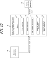
- FIG. 10 is a diagram illustrating a configuration example of a sintering process control unit 10 according to an embodiment.
- the sintering process control unit 10 includes a memory 11, a first predictor 12, a second predictor 13, a step response calculator 14, an operation amount calculator 15, and a guidance operation amount presenter 16.
- the sintering process control unit 10 acquires the actual values and target values in the operating process of the sintering machine from the operation data server 60.
- the actual values may include various measurement values and current manipulated variables that indicate operating conditions.
- the target value is the BRP target value.
- the operation data server 60 is capable of communicating with the sintering process control unit 10 via a network and may, for example, be realized on a computer that manages the production of sintered ore.
- the network is, for example, the Internet.
- the sintering process control unit 10 executes the aforementioned processing, i.e., processing to predict the BRP using a physical model and to determine the operation amounts of specified manipulated variables, such as the bed gas flow rate, so that the future BRP is maintained near a target value.
- the sintering process control unit 10 includes a function to include the operation amounts of the specified manipulated variables in the guidance operation amounts for presentation via the guidance operation amount presenter 16, thereby functioning as an operation guidance apparatus.
- a display 30 displays the guidance operation amounts outputted from the sintering process control unit 10 (operation guidance apparatus).
- the sintering process control unit 10 may be configured by a computer separate from the operation data server 60 (for example, a process computer that manages operation of the sintering machine, or a sintering process control calculation server 10A as in the example in FIG. 12 ).
- the display 30 may be a display apparatus such as a liquid crystal display (LCD) or an organic electro-luminescence panel (OLED panel).
- the display 30 may be realized by the display of a terminal apparatus 30A (see FIG. 12 ), such as a smartphone or tablet.
- the terminal apparatus 30A can communicate with the sintering process control unit 10 via the network.
- the memory 11 stores a physical model.
- the memory 11 also stores programs and data related to control of the sintering process.
- the memory 11 may store the acquired actual values and target values.
- the memory 11 may store various types of information (for example, the characteristic curves illustrated in FIGS. 3 to 6 ) obtained by the processing for controlling the sintering process.
- the memory 11 may include any storage devices, such as semiconductor storage devices, optical storage devices, and magnetic storage devices.
- a semiconductor storage device may, for example, include a semiconductor memory.
- the memory 11 may include a plurality of types of storage devices.
- the first predictor 12 determines a first predicted value of a control variable in the future for a case in which current manipulated variables are maintained using the physical model.
- the control variable is the BRP in the present embodiment.
- the second predictor 13 determines a second predicted value of the control variable in the future for a case in which the specified manipulated variables are changed using the physical model.
- the specified manipulated variables are a portion of the manipulated variables, and the step response of the BRP is determined in the case in which each of the specified manipulated variables is changed by a unit amount.
- the step response calculator 14 calculates a step response for the specified manipulated variables based on the first predicted value and the second predicted value.
- the operation amount calculator 15 calculates the operation amounts of the specified manipulated variables to reduce the deviation between the target value and the superimposed predicted value of the control variable based on the first predicted value and the step response.
- the superimposed predicted value is calculated using Expression (6) above.
- the operation amounts of the specified manipulated variables are calculated using the evaluation function J.
- the evaluation function J has a term corresponding to the deviation and a term corresponding to the operation amount of the specified manipulated variable.
- the guidance operation amount presenter 16 presents, on the display 30 as guidance operation amounts, the operation amounts of the specified manipulated variables that were calculated.
- the guidance operation amount presenter 16 may output, to the display 30, information such as the free response prediction curve as illustrated in FIGS. 3 to 6 , the prediction curve in the case of changing a portion of the manipulated variables (specified manipulated variables), and the curve illustrating the step response of the BRP.
- the operator may change the operating conditions of the sintering machine based on the guidance operation amounts displayed on the display 30.
- Such operation guidance for the sintering machine can also be implemented as part of a production process for producing sintered ore.
- the sintering process control unit 10 can be realized by a computer as described above, for example.
- the computer includes a memory and hard disk drive (storage device), a CPU (processing unit), and the like, for example.
- Programs can be stored on the hard disk drive and read from the hard disk drive into memory when the programs are to be executed by the CPU. Data during processing is stored in the memory and on the HDD as necessary.
- the memory 11 may, for example, be realized by a storage device.
- the first predictor 12, second predictor 13, step response calculator 14, operation amount calculator 15, and guidance operation amount presenter 16 may, for example, be realized by the CPU reading and executing programs.
- FIG. 11 is a flowchart illustrating a method of controlling a sintering process according to an embodiment.
- the sintering process control unit 10 calculates, and outputs as guidance operation amounts, the operation amounts of the specified manipulated variables according to the flowchart illustrated in FIG. 11 .
- the method of controlling a sintering process illustrated in FIG. 11 is also an operation guidance method and may be executed as part of a method of producing sintered ore.
- the sintering process control unit 10 acquires actual values and target values (step S1).
- the first predictor 12 determines a first predicted value of a control variable in the future for a case in which current manipulated variables are maintained using the physical model (step S2, first prediction step).
- the second predictor determines a second predicted value of the control variable in the future for a case in which the specified manipulated variable is changed using the physical model (step S3, second prediction step).
- the step response calculator 14 calculates a step response for the specified manipulated variable based on the first predicted value and the second predicted value (step S4, step response calculation step).
- the operation amount calculator 15 calculates the operation amounts of the specified manipulated variables to reduce the deviation between the target value and the superimposed predicted value of the control variable based on the first predicted value and the step response for the specified manipulated variables (step S5, operation amount calculation step).
- the guidance operation amount presenter 16 presents, as guidance operation amounts, the operation amounts of the specified manipulated variables that were calculated (step S6, guidance operation amount presentation step).
- FIG. 12 is a diagram illustrating a configuration example of a sintering operation guidance system according to an embodiment.
- the sintering operation guidance system can be configured to include the operation data server 60, the sintering process control unit 10, and the terminal apparatus 30A.
- the operation data server 60 includes a database storing operation data acquired from each device in a sintering process and operation control target values of the sintering process.
- the sintering process control unit 10 is realized by the sintering process control calculation server 10A, which is a server computer that can communicate with the operation data server 60 and the terminal apparatus 30A via a network.
- the sintering process control calculation server 10A which is a server computer that can communicate with the operation data server 60 and the terminal apparatus 30A via a network.
- the sintering process control calculation server 10A includes the memory 11, the first predictor 12, the second predictor 13, the step response calculator 14, the operation amount calculator 15, and the guidance operation amount presenter 16.
- the sintering process control calculation server 10A further includes an operation amount transmitter 17.
- the operation amount transmitter 17 transmits, to each device in the sintering process, the operation amounts of the specified manipulated variables calculated by the operation amount calculator 15 or operation amounts of the specified manipulated variables as corrected by the operator.
- the operation amounts of the specified manipulated variables as corrected by the operator are obtained from the terminal apparatus 30A.
- the terminal apparatus 30A includes a guidance operation amount display 31, an input interface for change in operation amount 32, and a transmitter for input of change in operation amount 33.
- the guidance operation amount display 31 acquires and displays the guidance operation amounts from the sintering process control calculation server 10A.
- the guidance operation amounts include the operation amounts of the specified manipulated variables calculated by the operation amount calculator 15 and are outputted from the guidance operation amount presenter 16.
- the input interface for change in operation amount 32 acquires input of a change in the operation amount of a specified manipulated variable from the operator.
- the input interface for change in operation amount 32 may, for example, be realized by a touch panel included in the terminal apparatus 30A.
- the transmitter for input of change in operation amount 33 transmits the input of the change in the operation amount of a specified manipulated variable to the sintering process control calculation server 10A.
- the transmitter for input of change in operation amount 33 may transmit a signal indicating no change to the sintering process control calculation server 10A in the case of no change by the operator.
- the operation amount transmitter 17 transmits, to each device in the sintering process, the operation amounts of the specified manipulated variables after correction by the operator, but in the case of acquiring the signal indicating no change, the operation amount transmitter 17 may transmit the operation amounts of the specified manipulated variables calculated by the operation amount calculator 15.
- the method of controlling a sintering process (operation guidance method), the method of producing sintered ore, the sintering process control unit 10 (operation guidance apparatus), and the sintering operation guidance system according to the present embodiment can present appropriate operation actions that take into account the time delay of the process.
- the terminal apparatus 30A according to the present embodiment is used to present appropriate operation actions that take into account the time delay of the process.
- the operator can change the operating conditions based on the indicated guidance operation amounts to keep the feature values of the temperature distribution (heat pattern) of the sintering raw material near the target values, thus improving the yield in the production of sintered ore.
- the configuration of the sintering process control unit 10 as illustrated in FIG. 10 is an example.
- the sintering process control unit 10 need not include all of the components illustrated in FIG. 10 .
- the sintering process control unit 10 may include components other than those illustrated in FIG. 10 .
- the sintering process control unit 10 may be configured to further include a display 30.
- the second prediction step (step S3) and the step response calculation step (step S4) may be omitted in the flowchart of FIG. 11 when the step response calculated in advance and stored in the memory 11 is used.
- the calculated operation amounts are presented as guidance operation amounts and are reflected in the sintering process through a final decision by the operator.
- Such operation guidance has been described as being implemented as part of a production method for producing sintered ore.
- the sintering process control unit 10 may directly output the calculated operation amounts of the specified manipulated variables that were calculated to the facility for producing sintered ore, and the manipulated variables may be automatically updated by the facility.
- the calculation of the operation amounts of the specified manipulated variables in the method of controlling the return ore ratio according to the present embodiment may be performed as part of a production method for producing sintered ore, without having to pass through the stage of operation guidance to the operator.
- the equipment from which the operation amounts operating volume of the specified manipulated variables are outputted may, for example, be the sintering machine or a process computer that manages the sintering process.
- the manipulated variables are automatically updated by the equipment, operations can be carried out without operator intervention, freeing the operator from the task of determining the operation amounts so that the operator can concentrate on monitoring the entire process for the stable production of high-grade sintered ore.
Landscapes
- Engineering & Computer Science (AREA)
- Chemical & Material Sciences (AREA)
- Manufacturing & Machinery (AREA)
- Geochemistry & Mineralogy (AREA)
- Geology (AREA)
- General Life Sciences & Earth Sciences (AREA)
- Life Sciences & Earth Sciences (AREA)
- Environmental & Geological Engineering (AREA)
- Materials Engineering (AREA)
- Mechanical Engineering (AREA)
- Metallurgy (AREA)
- Organic Chemistry (AREA)
- Manufacture And Refinement Of Metals (AREA)
Abstract
Description
- The present disclosure relates to a method of controlling a sintering process, an operation guidance method, a method of producing sintered ore, a sintering process control unit, an operation guidance apparatus, a sintering operation guidance system, and a terminal apparatus.
- In the steelmaking industry, iron ore grades are declining due to years of mining. A higher proportion of fine ore, which is dressed at the mine to have a high fineness ratio, is therefore in use, and the sintering process, whereby sintered ore is produced by condensing fine ore before the ore is charged into a blast furnace, has become more important. To secure gas permeability in the blast furnace, sintered ore with less than a predetermined grain size is not charged into the blast furnace, but rather is sintered again in a sintering machine as return ore. The improvement of yield, i.e., the percentage that is at least a predetermined grain size, is directly related to the productivity of the sintering machine. A strong demand to improve yield therefore exists.
-
FIG. 1 is a diagram illustrating an overview of the sintering process. At the entry side of the sintering machine, fine ore, coke breeze, limestone, quicklime, and the like are mixed and granulated into a sintering raw material (quasiparticles) via a surge hopper. The sintering raw material is melted by the heat of combustion of coke breeze in the sintering machine. Quasiparticles are then fused to each other, cooled by air drawn from the top, and discharged. The heat pattern during this series of heating and cooling processes has a significant impact on product yield. The heat pattern is the temperature distribution of the sintering raw material in the longitudinal and thickness directions of the sintering machine. - Although it is difficult to actually measure heat patterns, the Burn Rising Point (BRP) and Burn Through Point (BTP) are known as feature values of the heat pattern that can be measured. The BRP is the position in the longitudinal direction where the exhaust gas temperature in the wind box at the bottom of the sintering machine exceeds a threshold. The BTP is the position in the longitudinal direction where the temperature of the exhaust gas measured at the wind box at the bottom of the sintering machine is the highest.
- Here, as conventional heat pattern control methods, Patent Literature (PTL) 1 and
PTL 2 disclose methods to control the position of the BTP to be constant. -
- PTL 1:
JP 2005-187841 A - PTL 2:
JP 2006-307259 A - Here, the control in
PTL - It is an aim of the present disclosure to provide a method of controlling a sintering process, an operation guidance method, a method of producing sintered ore, a sintering process control unit, an operation guidance apparatus, a sintering operation guidance system, and a terminal apparatus that can present appropriate operation actions that take into account the time delay of a process.
-
- (1) A method of controlling a sintering process according to an embodiment of the present disclosure is
a method of controlling a sintering process using a physical model capable of calculating a state of the sintering process including a temperature distribution of sintering raw material in a longitudinal direction and a thickness direction in a sintering machine, the method including:- a first prediction step of determining a first predicted value of a control variable in the future for a case in which current manipulated variables are maintained using the physical model; and
- an operation amount calculation step of calculating an operation amount of at least one specified manipulated variable, which is a portion of the manipulated variables, to reduce a deviation between a target value and a superimposed predicted value of the control variable, the superimposed predicted value being based on the first predicted value and a step response for a case in which the specified manipulated variable is changed by a unit amount.
- (2) As an embodiment of the present disclosure, (1) further includes
- a second prediction step of determining a second predicted value of the control variable in the future for a case in which the specified manipulated variable is changed using the physical model; and
- a step response calculation step of calculating a step response for the specified manipulated variable based on the first predicted value and the second predicted value.
- (3) As an embodiment of the present disclosure, in (1) or (2),
the control variable is a feature value of a temperature distribution of the sintering raw material. - (4) As an embodiment of the present disclosure, in (3),
the control variable is the BRP or the BTP. - (5) As an embodiment of the present disclosure, in any one of (1) to (4),
in the operation amount calculation step, the operation amount of the specified manipulated variable is calculated to minimize or maximize an evaluation function having a term corresponding to the deviation and a term corresponding to the operation amount of the specified manipulated variable. - (6) As an embodiment of the present disclosure, in any one of (1) to (5),
the at least one specified manipulated variable includes at least one of pallet speed, bed gas flow rate, agglomeration agent ratio, and raw material water content. - (7) An operation guidance method according to an embodiment of the present disclosure includes
a guidance operation amount presentation step of presenting, as a guidance operation amount, an operation amount of the specified manipulated variable calculated by the method of controlling a sintering process of any one of (1) to (6). - (8) A method of producing sintered ore according to an embodiment of the present disclosure includes
producing sintered ore using the guidance operation amount presented by the operation guidance method of (7). - (9) A method of producing sintered ore according to an embodiment of the present disclosure includes
producing sintered ore using the operation amount of the specified manipulated variable calculated by the method of controlling a sintering process of any one of (1) to (6). - (10) A sintering process control unit according to an embodiment of the present disclosure is
a sintering process control unit for controlling a sintering process using a physical model capable of calculating a state of the sintering process including a temperature distribution of sintering raw material in a longitudinal direction and a thickness direction in a sintering machine, the sintering process control unit including:- a first predictor configured to determine a first predicted value of a control variable in the future for a case in which current manipulated variables are maintained using the physical model; and
- an operation amount calculator configured to calculate an operation amount of at least one specified manipulated variable, which is a portion of the manipulated variables, to reduce a deviation between a target value and a superimposed predicted value of the control variable, the superimposed predicted value being based on the first predicted value and a step response for a case in which the specified manipulated variable is changed by a unit amount.
- (11) An operation guidance method according to an embodiment of the present disclosure includes
a guidance operation amount presenter configured to present, as a guidance operation amount, an operation amount of the specified manipulated variable calculated by the sintering process control unit of (10). - (12) A sintering operation guidance system according to an embodiment of the present disclosure is
- a sintering operation guidance system including an operation data server, a sintering process control unit, and a terminal apparatus, wherein
- the operation data server includes a database storing operation data acquired from each device in a sintering process and operation control target values of the sintering process,
- the sintering process control unit includes
- a first predictor configured to determine a first predicted value of a control variable in the future for a case in which current manipulated variables are maintained using a physical model capable of calculating a state of the sintering process including a temperature distribution of sintering raw material in a longitudinal direction and a thickness direction in a sintering machine,
- an operation amount calculator configured to calculate an operation amount of at least one specified manipulated variable, which is a portion of the manipulated variables, to reduce a deviation between a target value and a superimposed predicted value of the control variable, the superimposed predicted value being based on the first predicted value and a step response for a case in which the specified manipulated variable is changed by a unit amount,
- a guidance operation amount presenter configured to output a guidance operation amount including the operation amount of the specified manipulated variable, and
- an operation amount transmitter configured to transmit, to each device in the sintering process, the operation amount of the specified manipulated variable calculated by the operation amount calculator or an operation amount of the specified manipulated variable as corrected by an operator, and
- the terminal apparatus includes
- a guidance operation amount display configured to acquire and display the guidance operation amount from the sintering process control unit,
- an input interface for change in operation amount configured to acquire input of a change in the operation amount of the specified manipulated variable from the operator, and
- a transmitter for input of change in operation amount configured to transmit the input of the change to the sintering process control unit.
- (13) A terminal apparatus according to an embodiment of the present disclosure includes
- a guidance operation amount display configured to acquire and display a guidance operation amount, including an operation amount of a specified manipulated variable, from a sintering process control unit;
- an input interface for change in operation amount configured to acquire input of a change in the operation amount of a specified manipulated variable from an operator; and
- a transmitter for input of change in operation amount configured to transmit the input of the change to the sintering process control unit, wherein
- the operation amount of the specified manipulated variable is calculated by the sintering process control unit to reduce a deviation between a target value and a superimposed predicted value of a control variable, the superimposed predicted value being based on a first predicted value and a step response for a case in which the specified manipulated variable, which is a portion of manipulated variables, is changed by a unit amount, the first predicted value being a predicted value of the control variable in the future for a case in which current manipulated variables are maintained and being determined using a physical model capable of calculating a state of a sintering process including a temperature distribution of sintering raw material in a longitudinal direction and a thickness direction in a sintering machine.
- According to the present disclosure, a method of controlling a sintering process, an operation guidance method, a method of producing sintered ore, a sintering process control unit, an operation guidance apparatus, a sintering operation guidance system, and a terminal apparatus that can present appropriate operation actions that take into account the time delay of a process can be provided.
- In the accompanying drawings:
-
FIG. 1 is a diagram illustrating an overview of the sintering process; -
FIG. 2 is a diagram illustrating input/output information of a physical model used in the present disclosure; -
FIG. 3 is a diagram illustrating predicted values of the BRP; -
FIG. 4 is a diagram illustrating the step response of the BRP when the pallet speed is increased by a unit amount; -
FIG. 5 is a diagram illustrating predicted values of the BRP; -
FIG. 6 is a diagram illustrating the step response of the BRP when the bed gas flow rate is increased by a unit amount; -
FIG. 7 is a diagram illustrating the change in the actual value and the estimated value of the bed gas flow rate; -
FIG. 8 is a diagram illustrating the change in explanatory variables in an estimation equation for the bed gas flow rate; -
FIG. 9 is a diagram illustrating the BRP, pallet speed, and quicklime ratio when operation guidance was implemented; -
FIG. 10 is a diagram illustrating a configuration example of a sintering process control unit according to an embodiment; -
FIG. 11 is a flowchart illustrating a method of controlling a sintering process (operation guidance method) according to an embodiment; and -
FIG. 12 is a diagram illustrating a configuration example of a sintering operation guidance system according to an embodiment. - A method of controlling a sintering process, an operation guidance method, a method of producing sintered ore, a sintering process control unit, an operation guidance apparatus, a sintering operation guidance system, and a terminal apparatus according to an embodiment of the present disclosure will be described below with reference to the drawings.
- As mentioned above, the BRP and the BTP are examples of feature values of a heat pattern. The BRP is used as an index of the heat pattern in the present embodiment, and a control method to keep this index constant is described. As an overview, the method of controlling a sintering process according to the present embodiment uses a physical model of a sintering machine to predict the heat pattern with high accuracy and to determine the operation amounts of manipulated variables, such as the bed gas flow rate, so that the future BRP is maintained near a target value. Here, the BTP can also be used as an index of the heat pattern by replacing the BRP with the BTP in the description below.
- The physical model used in the present disclosure is the same as the model of the method described in the reference Yamaoka et al., ISIJ International, Vol. 45, No. 4, pp. 522. That is, the physical model consists of a set of partial differential equations that take into account the physical phenomena of combustion of coke breeze, thermal decomposition of limestone, and evaporation of moisture, and that can calculate the state inside the sintering machine. In the present embodiment, this physical model is a two-dimensional non-steady state model that can calculate the state of the sintering process, including the temperature distribution (heat pattern) of sintering raw material in the longitudinal direction and thickness direction in the sintering machine. The BRP can also be known from the calculated heat pattern.
- As illustrated in
FIG. 2 , among the input variables given to the non-steady state model, the main input variables that vary with time are the pallet speed, exhaust gas flow rate, raw material bulk density, raw material water content, raw material limestone ratio, and raw material coke ratio. These input variables can be the manipulated variables or manipulation factors of the sintering machine. Here, as discussed below, direct operation may be difficult depending on the type of exhaust gas flow rate. The pallet speed is the speed at which the pallet of the sintering machine on which the sintering raw material is placed moves. The exhaust gas flow rate is the flow rate per unit time of the exhaust gas from the sintering machine and can be regulated by an exhaust fan, for example. The raw material bulk density is the bulk density of the sintering raw material as calculated from the layer thickness, sintering machine width, and the like. The raw material water content, raw material limestone ratio, and raw material coke ratio are the ratios of water, limestone, and coke, respectively, in the sintering raw material. Coke is the main agglomeration agent, and the raw material coke ratio is also referred to as the agglomeration agent ratio. - The main output variables of the physical model are the BTP, the exhaust gas composition, and the BRP. The exhaust gas composition includes the ratios of O2, CO2, and CO. The output variables, which change from moment to moment, are calculated using the physical model. The time interval for this calculation (the time difference between "t + 1" and "t" in the physical model equations described below) is not particularly limited, but may be one minute as an example.
- The physical model can be expressed by Expressions (1) and (2) below.

- Here, u(t) represents the aforementioned input variables, which can be manipulated by the operator of the sintering machine, and x(t) represents state variables calculated in the physical model. The state variables are, for example, the heat pattern in the sintering machine, the coke reaction rate, and the gas fractions of CO, CO2, and the like. Also, y(t) is the aforementioned output variables, such as the BTP, the O2 ratio in the exhaust gas composition, the CO2 ratio, the BRP, and the like. In the present embodiment, y(t) includes at least the BRP. Here, the output variables of y(t), such as the BTP, the exhaust gas composition, and the BRP, are also referred to as control variables. Control variables are variables that should be controlled during operation, but which are difficult or impossible to manipulate directly and are thus changed via correlated manipulated variables.
- A model predictive control system is constructed to control the BRP using the physical model in Expressions (1) and (2). The detailed configuration of the model predictive control system (control unit) is described below, whereas the processing is described here. In the model predictive control system, the future BRP is predicted first assuming that the current input variables hold in the future. The BRP(yf(t0 + k)) is determined under the fixed condition that u(t0 + k) = u(t0) with the current time step as t0. The response yf(t) determined in this way is called the free response. Hereafter, the predicted value in the free response is also referred to as the "first predicted value".
FIG. 3 is a diagram illustrating predicted values of the BRP. The BRP is indicated by the distance [m] from the surge hopper position in the movement direction of the pallet. In the example inFIG. 3 , the point in time at which the prediction is made (the aforementioned "current time") is indicated by t0 = 0, and the prediction is made for 90 minutes ahead. That is, in u(t0 + k) = u(t0), k is from 1 to 90. InFIG. 3 , the free response is indicated as a solid line ("no action" inFIG. 3 ). - In the model predictive control system, predictions are made by changing a portion of the manipulated variables (corresponding to the specified manipulated variables described below) among u(t), which are the aforementioned input variables. Hereafter, the predicted value when a portion of the manipulated variables is changed is also referred to as the "second predicted value". In the example in
FIG. 3 , the pallet speed was changed (increased) by ΔPS0. The BRP(y'(t0 + k)) was determined under the condition that u(t0 + k) = u(t0) + Δu1, where Δu1 is the change in the input variable corresponding to a change of ΔPS0 in the pallet speed. The predicted values of the BRP in this case are illustrated by the dashed line ("pallet speed increase" inFIG. 3 ). - Furthermore, the step response of the BRP is determined in the model predictive control system.
FIG. 4 is a diagram illustrating the step response of the BRP when the pallet speed is increased by a unit amount. By taking the difference between the solid and dashed lines inFIG. 3 and converting the ΔPS0 of the pallet speed to a unit amount, the step response of the BRP is obtained as illustrated inFIG. 4 . The step response, SPS(k | t0), is illustrated in Expression (3) below.
[Math. 2]
- As illustrated in
FIG. 3 , as the pallet speed increases, the BRP moves to the exit side of the sintering machine. Here, in the present embodiment, the predicted value yielded by changing a portion of the manipulated variables is also determined when determining the predicted value of the free response of the BRP, and the step response is calculated from the difference of these predicted values. However, it is also possible to use values calculated beforehand (in advance). - In the examples in
FIGS. 3 and4 , the manipulated variable to be changed is the palette speed, but other manipulated variables may be changed. The following describes a case in which predictions are made after changing the bed gas flow rate in the model predictive control system. Here, the bed gas flow rate is one specific example of the exhaust gas flow rate and is the flow rate of exhaust gas in the lower portion of the sintering bed. - In the model predictive control system, the predicted value of the BRP in the free response is determined in the same way as above.
FIG. 5 is a diagram illustrating predicted values of the BRP. InFIG. 5 , the free response is indicated as a solid line ("no action" inFIG. 5 ). - In the example in
FIG. 5 , the bed gas flow rate was changed (increased) by Δv0. The BRP(y'(t0 + k)) was determined under the condition that u(t0 + k) = u(t0) + Δu2, where Δu2 is the change in the input variable corresponding to a change of Δv0 in the bed gas flow rate. The predicted values of the BRP in this case are illustrated by the dashed line ("air flow rate increase" inFIG. 5 ). - Furthermore, the step response of the BRP is determined in the model predictive control system.
FIG. 6 is a diagram illustrating the step response of the BRP when the bed gas flow rate is increased by a unit amount. By taking the difference between the solid and dashed lines inFIG. 5 and converting the Δv0 of the bed gas flow rate to a unit amount, the step response of the BRP is obtained as illustrated inFIG. 6 . In this case, the step response, Sv(k | t0), is illustrated in Expression (4) below.
[Math. 3]
- As illustrated in
FIG. 5 , as the bed gas flow rate increases, the BRP moves to the entry side of the sintering machine, because sintering proceeds more quickly. - In the model predictive control system, the evaluation function J is used to determine the operation amounts of the manipulated variables, for which the step response was determined, so as to reduce the deviation between the predicted value and target value of the BRP. For example, in a case in which the step response of the BRP when the pallet speed and bed gas flow rate are increased by a unit amount is determined, the operation amount of the pallet speed (ΔPS) and the operation amount of the bed gas flow rate (Δv) are determined using the evaluation function J. To reduce the predicted deviation of the BRP in the prediction interval (from the time of prediction to 90 minutes ahead in the above example), and also to reduce excessive manipulation of each manipulated variable (an excessive operation amount), the evaluation function J can be Expression (5) below, for example.
[Math. 4]
- In the model predictive control system, the operation amount of the pallet speed (ΔPS) and the operation amount of the bed gas flow rate (Δv) are determined so as to minimize the evaluation function J in Expression (5). The weight coefficients, a and b, in Expression (5) may be used to adjust which manipulated variables are selected or combined. For example, by setting b = 0, it is possible to manipulate only the pallet speed. Here, yref is the target value of the BRP, and ypre is the predicted value of the BRP. As an assumption for predictive control using this physical model, it may be assumed that the future BRP can be approximated by superimposing the response yf(t), which is the free response, and the step response. The predicted value of the BRP, i.e., ypre (superimposed predicted value), can be expressed by Expression (6) below.
[Math. 5]
- In the following, a portion of the manipulated variables for which a step response is obtained in a case in which the manipulated variables are changed by a unit amount are referred to as "specified manipulated variables". The terms in Expressions (5) and (6) for the operation amounts (ΔPS and Δv) can be increased or decreased depending on the specified manipulated variables. For example, in a case of further determining the step response of the BRP (SCR(k | t0)) when the agglomeration agent ratio is increased by a unit amount, a term for the operation amount (ΔCR) of the agglomeration agent ratio is added. In other words, the term "+c(ΔCR)2" is added to Expression (5) with c as a weighting factor, and the term "+SCR(k | t0) × ΔCR" is added to Expression (6). For example, in a case of further determining the step response of the BRP (SWR(k | t0)) when the raw material water content is increased by a unit amount, a term for the operation amount (ΔWR) of the raw material water content is added. In other words, the term "+d(ΔWR)2" is added to Expression (5) with d as a weighting factor, and the term "+SWR(k | t0) × ΔWR" is added to Expression (6). For example, in a case in which the step response of the BRP when the pallet speed is increased by a unit amount is not determined, the term "+a(ΔPS)2" may be excluded from Expression (5), or a may be set to 0, and the term "+Sps(k | t0) × ΔPS" may be excluded from Expression (6).
- Here, Expression (6) is a linear expression for the operation amounts (ΔPS and Δv) of the specified manipulated variables, which are unknown variables, and the evaluation function J is a quadratic expression for the unknown variables. Therefore, ΔPS and Δv can be determined by quadratic programming.
- In the present embodiment, the case in which the specified manipulated variables are the pallet speed and the bed gas flow rate is specifically described, but the specified manipulated variables are not limited to these. For example, the specified manipulated variables may include at least one of the pallet speed, bed gas flow rate, agglomeration agent ratio (raw material coke ratio), and raw material water content, or other variables may be used. Although the unknown variables are determined for the case in which the evaluation function J is minimized in the present embodiment, the evaluation function J may be designed so that the minimization of the deviation between the predicted value and target value of the BRP and the minimization of the operation amounts of the unknown variables correspond to the maximization of the evaluation function J. In other words, the operation amounts of the unknown variables may be determined so that the evaluation function J is minimized or maximized.
- The specified manipulated variables are not limited to manipulated variables that can be directly manipulated by the operator. In the case in which the bed gas flow rate is used as a specified manipulated variable, an operation amount of a manipulated variable that is correlated with the bed gas flow rate and can be directly manipulated is further determined, since it is difficult to manipulate the bed gas flow rate directly. A case in which the operation amount of the quicklime ratio is calculated to manipulate the bed gas flow rate is described below.
- The bed gas flow rate depends on the gas permeability resistance of the sintering bed. The gas permeability resistance can be suppressed by mixing the fine ore that is the raw material with quicklime, which acts as a binder, to form quasiparticles. To quantify the sensitivity of the quicklime ratio relative to the bed gas flow rate, a regression formula, i.e., an estimation formula for the bed gas flow rate (v), can be expressed by Expression (7) below.
[Math. 6]
- Here, M is the number of explanatory variables and is assumed to be "5" in the present embodiment, and pi and qi are coefficients. The manipulated variables x1 to x5, which are correlated with the bed gas flow rate (v), are the damper opening degree, quicklime ratio, layer thickness, return ore ratio, and raw material water content, respectively. The damper opening degree is the degree of opening of the air flow rate control damper for adjusting the air flow rate under the bed and is, for example, 100% when fully open. The quicklime ratio is the percentage of quicklime in the sintering raw material. The layer thickness is the thickness of the layer of sintering raw material on the pallet. The return ore ratio is the percentage of return ore in the sintered ore after firing. The raw material water content is the percentage of water in the sintering raw material. These explanatory variables are non-limiting examples, and any combination of factors that affect the bed gas flow rate may be adopted.
-
FIG. 7 illustrates estimated values using Expression (7) and actual values.FIG. 8 also illustrates the changes in the five manipulated variables over the same estimation period as inFIG. 7 . The changes in the five manipulated variables are illustrated as differences from typical operating conditions. With aCaO as the partial regression coefficient of quicklime in Expression (7), the operation amount of the quicklime ratio, i.e., ΔCaO, is determined by the formula "Δv0pt/aCaO". Here, Δv0pt is the optimal operation amount of the bed gas flow rate as calculated by the above processing using the evaluation function J. - The model predictive control system outputs the optimal operation amounts determined by the above processing so that the process computer that manages the sintering process can reflect the optimal operation amount. Here, the output of the optimal operation amounts includes output as guidance to the operator who is operating the sintering machine. During output as guidance, not only information on the optimal operation amounts, but also, for example, information on the free response prediction curve as illustrated in
FIGS. 3 to 6 , the prediction curve in the case of changing a portion of the manipulated variables (specified manipulated variables), and the curve illustrating the step response of the BRP may be outputted. In other words, the information outputted as operation guidance includes at least the guidance operation amounts (optimal operation amounts) and may be displayed on a display that can be seen by the operator. -
FIG. 9 illustrates an example in which the optimal operation amounts of the pallet speed and quicklime ratio are determined by the above control method, presented to the operator as guidance information, and then reflected in the sintering process by the operator's final decision. In the example illustrated inFIG. 9 , it was possible to keep the BRP near the target value (approximately in the range of -1.0 m to +1.0 m relative to the target value). -
FIG. 10 is a diagram illustrating a configuration example of a sinteringprocess control unit 10 according to an embodiment. As illustrated inFIG. 10 , the sinteringprocess control unit 10 includes amemory 11, afirst predictor 12, asecond predictor 13, astep response calculator 14, anoperation amount calculator 15, and a guidanceoperation amount presenter 16. The sinteringprocess control unit 10 acquires the actual values and target values in the operating process of the sintering machine from theoperation data server 60. The actual values may include various measurement values and current manipulated variables that indicate operating conditions. The target value is the BRP target value. Theoperation data server 60 is capable of communicating with the sinteringprocess control unit 10 via a network and may, for example, be realized on a computer that manages the production of sintered ore. The network is, for example, the Internet. The sinteringprocess control unit 10 executes the aforementioned processing, i.e., processing to predict the BRP using a physical model and to determine the operation amounts of specified manipulated variables, such as the bed gas flow rate, so that the future BRP is maintained near a target value. In the present embodiment, the sinteringprocess control unit 10 includes a function to include the operation amounts of the specified manipulated variables in the guidance operation amounts for presentation via the guidanceoperation amount presenter 16, thereby functioning as an operation guidance apparatus. Adisplay 30 displays the guidance operation amounts outputted from the sintering process control unit 10 (operation guidance apparatus). The sinteringprocess control unit 10 may be configured by a computer separate from the operation data server 60 (for example, a process computer that manages operation of the sintering machine, or a sintering processcontrol calculation server 10A as in the example inFIG. 12 ). Thedisplay 30 may be a display apparatus such as a liquid crystal display (LCD) or an organic electro-luminescence panel (OLED panel). Thedisplay 30 may be realized by the display of aterminal apparatus 30A (seeFIG. 12 ), such as a smartphone or tablet. Theterminal apparatus 30A can communicate with the sinteringprocess control unit 10 via the network. A sintering operation guidance system may be configured by the sintering processcontrol calculation server 10A that has the functions of the sinteringprocess control unit 10 and theterminal apparatus 30A that has the function of thedisplay 30. The sintering processcontrol calculation server 10A and theterminal apparatus 30A may be in the same location (for example, in the same plant) or physically located apart. The sintering operation guidance system may be configured to include anoperation data server 60. - The components of the sintering
process control unit 10 are described below. Thememory 11 stores a physical model. Thememory 11 also stores programs and data related to control of the sintering process. Thememory 11 may store the acquired actual values and target values. Thememory 11 may store various types of information (for example, the characteristic curves illustrated inFIGS. 3 to 6 ) obtained by the processing for controlling the sintering process. Thememory 11 may include any storage devices, such as semiconductor storage devices, optical storage devices, and magnetic storage devices. A semiconductor storage device may, for example, include a semiconductor memory. Thememory 11 may include a plurality of types of storage devices. - The
first predictor 12 determines a first predicted value of a control variable in the future for a case in which current manipulated variables are maintained using the physical model. The control variable is the BRP in the present embodiment. - The
second predictor 13 determines a second predicted value of the control variable in the future for a case in which the specified manipulated variables are changed using the physical model. As described above, the specified manipulated variables are a portion of the manipulated variables, and the step response of the BRP is determined in the case in which each of the specified manipulated variables is changed by a unit amount. - The
step response calculator 14 calculates a step response for the specified manipulated variables based on the first predicted value and the second predicted value. - The
operation amount calculator 15 calculates the operation amounts of the specified manipulated variables to reduce the deviation between the target value and the superimposed predicted value of the control variable based on the first predicted value and the step response. The superimposed predicted value is calculated using Expression (6) above. In the present embodiment, the operation amounts of the specified manipulated variables are calculated using the evaluation function J. As in Expression (5) above, the evaluation function J has a term corresponding to the deviation and a term corresponding to the operation amount of the specified manipulated variable. - The guidance
operation amount presenter 16 presents, on thedisplay 30 as guidance operation amounts, the operation amounts of the specified manipulated variables that were calculated. In addition to the guidance operation amounts, the guidanceoperation amount presenter 16 may output, to thedisplay 30, information such as the free response prediction curve as illustrated inFIGS. 3 to 6 , the prediction curve in the case of changing a portion of the manipulated variables (specified manipulated variables), and the curve illustrating the step response of the BRP. - The operator may change the operating conditions of the sintering machine based on the guidance operation amounts displayed on the
display 30. Such operation guidance for the sintering machine can also be implemented as part of a production process for producing sintered ore. - The sintering
process control unit 10 can be realized by a computer as described above, for example. The computer includes a memory and hard disk drive (storage device), a CPU (processing unit), and the like, for example. Programs can be stored on the hard disk drive and read from the hard disk drive into memory when the programs are to be executed by the CPU. Data during processing is stored in the memory and on the HDD as necessary. Thememory 11 may, for example, be realized by a storage device. Thefirst predictor 12,second predictor 13,step response calculator 14,operation amount calculator 15, and guidanceoperation amount presenter 16 may, for example, be realized by the CPU reading and executing programs. -
FIG. 11 is a flowchart illustrating a method of controlling a sintering process according to an embodiment. The sinteringprocess control unit 10 calculates, and outputs as guidance operation amounts, the operation amounts of the specified manipulated variables according to the flowchart illustrated inFIG. 11 . The method of controlling a sintering process illustrated inFIG. 11 is also an operation guidance method and may be executed as part of a method of producing sintered ore. - The sintering
process control unit 10 acquires actual values and target values (step S1). Thefirst predictor 12 determines a first predicted value of a control variable in the future for a case in which current manipulated variables are maintained using the physical model (step S2, first prediction step). The second predictor determines a second predicted value of the control variable in the future for a case in which the specified manipulated variable is changed using the physical model (step S3, second prediction step). Thestep response calculator 14 calculates a step response for the specified manipulated variable based on the first predicted value and the second predicted value (step S4, step response calculation step). Theoperation amount calculator 15 calculates the operation amounts of the specified manipulated variables to reduce the deviation between the target value and the superimposed predicted value of the control variable based on the first predicted value and the step response for the specified manipulated variables (step S5, operation amount calculation step). The guidanceoperation amount presenter 16 presents, as guidance operation amounts, the operation amounts of the specified manipulated variables that were calculated (step S6, guidance operation amount presentation step). -
FIG. 12 is a diagram illustrating a configuration example of a sintering operation guidance system according to an embodiment. The sintering operation guidance system can be configured to include theoperation data server 60, the sinteringprocess control unit 10, and theterminal apparatus 30A. Here, in the example inFIG. 12 , theoperation data server 60 includes a database storing operation data acquired from each device in a sintering process and operation control target values of the sintering process. In the example inFIG. 12 , the sinteringprocess control unit 10 is realized by the sintering processcontrol calculation server 10A, which is a server computer that can communicate with theoperation data server 60 and theterminal apparatus 30A via a network. As inFIG. 10 , the sintering processcontrol calculation server 10A includes thememory 11, thefirst predictor 12, thesecond predictor 13, thestep response calculator 14, theoperation amount calculator 15, and the guidanceoperation amount presenter 16. The sintering processcontrol calculation server 10A further includes an operation amount transmitter 17. The operation amount transmitter 17 transmits, to each device in the sintering process, the operation amounts of the specified manipulated variables calculated by theoperation amount calculator 15 or operation amounts of the specified manipulated variables as corrected by the operator. Here, the operation amounts of the specified manipulated variables as corrected by the operator are obtained from theterminal apparatus 30A. Theterminal apparatus 30A includes a guidanceoperation amount display 31, an input interface for change inoperation amount 32, and a transmitter for input of change inoperation amount 33. The guidanceoperation amount display 31 acquires and displays the guidance operation amounts from the sintering processcontrol calculation server 10A. The guidance operation amounts include the operation amounts of the specified manipulated variables calculated by theoperation amount calculator 15 and are outputted from the guidanceoperation amount presenter 16. The input interface for change inoperation amount 32 acquires input of a change in the operation amount of a specified manipulated variable from the operator. The input interface for change inoperation amount 32 may, for example, be realized by a touch panel included in theterminal apparatus 30A. The transmitter for input of change inoperation amount 33 transmits the input of the change in the operation amount of a specified manipulated variable to the sintering processcontrol calculation server 10A. The transmitter for input of change inoperation amount 33 may transmit a signal indicating no change to the sintering processcontrol calculation server 10A in the case of no change by the operator. The operation amount transmitter 17 transmits, to each device in the sintering process, the operation amounts of the specified manipulated variables after correction by the operator, but in the case of acquiring the signal indicating no change, the operation amount transmitter 17 may transmit the operation amounts of the specified manipulated variables calculated by theoperation amount calculator 15. - As described above, the method of controlling a sintering process (operation guidance method), the method of producing sintered ore, the sintering process control unit 10 (operation guidance apparatus), and the sintering operation guidance system according to the present embodiment can present appropriate operation actions that take into account the time delay of the process. The
terminal apparatus 30A according to the present embodiment is used to present appropriate operation actions that take into account the time delay of the process. For example, the operator can change the operating conditions based on the indicated guidance operation amounts to keep the feature values of the temperature distribution (heat pattern) of the sintering raw material near the target values, thus improving the yield in the production of sintered ore. - While embodiments according to the present disclosure have been described with reference to the drawings and examples, it should be noted that various modifications and amendments may easily be implemented by those skilled in the art based on the present disclosure. Accordingly, such modifications and amendments are included within the scope of the present disclosure. For example, functions or the like included in each component, each step, or the like can be rearranged without logical inconsistency, and a plurality of components, steps, or the like can be combined into one or divided. Embodiments according to the present disclosure can also be realized as a program executed by a processor included in an apparatus or as a storage medium having the program recorded thereon. Such embodiments are also to be understood as included in the scope of the present disclosure.
- The configuration of the sintering
process control unit 10 as illustrated inFIG. 10 is an example. The sinteringprocess control unit 10 need not include all of the components illustrated inFIG. 10 . The sinteringprocess control unit 10 may include components other than those illustrated inFIG. 10 . For example, the sinteringprocess control unit 10 may be configured to further include adisplay 30. The second prediction step (step S3) and the step response calculation step (step S4) may be omitted in the flowchart ofFIG. 11 when the step response calculated in advance and stored in thememory 11 is used. - In the above embodiments, the calculated operation amounts are presented as guidance operation amounts and are reflected in the sintering process through a final decision by the operator. Such operation guidance has been described as being implemented as part of a production method for producing sintered ore. Here, the sintering
process control unit 10 may directly output the calculated operation amounts of the specified manipulated variables that were calculated to the facility for producing sintered ore, and the manipulated variables may be automatically updated by the facility. In other words, the calculation of the operation amounts of the specified manipulated variables in the method of controlling the return ore ratio according to the present embodiment may be performed as part of a production method for producing sintered ore, without having to pass through the stage of operation guidance to the operator. Here, the equipment from which the operation amounts operating volume of the specified manipulated variables are outputted may, for example, be the sintering machine or a process computer that manages the sintering process. In the case in which the manipulated variables are automatically updated by the equipment, operations can be carried out without operator intervention, freeing the operator from the task of determining the operation amounts so that the operator can concentrate on monitoring the entire process for the stable production of high-grade sintered ore. -
- 10
- Sintering process control unit
- 10A
- Sintering process control calculation server
- 11
- Memory
- 12
- First predictor
- 13
- Second predictor
- 14
- Step response calculator
- 15
- Operation amount calculator
- 16
- Guidance operation amount presenter
- 17
- Operation amount transmitter
- 30
- Display
- 30A
- Terminal apparatus
- 31
- Guidance operation amount display
- 32
- Input interface for change in operation amount
- 33
- Transmitter for input of change in operation amount
- 60
- Operation data server
Claims (13)
- A method of controlling a sintering process using a physical model capable of calculating a state of the sintering process including a temperature distribution of sintering raw material in a longitudinal direction and a thickness direction in a sintering machine, the method comprising:a first prediction step of determining a first predicted value of a control variable in the future for a case in which current manipulated variables are maintained using the physical model; andan operation amount calculation step of calculating an operation amount of at least one specified manipulated variable, which is a portion of the manipulated variables, to reduce a deviation between a target value and a superimposed predicted value of the control variable, the superimposed predicted value being based on the first predicted value and a step response for a case in which the specified manipulated variable is changed by a unit amount.
- The method of controlling a sintering process according to claim 1, further comprisinga second prediction step of determining a second predicted value of the control variable in the future for a case in which the specified manipulated variable is changed using the physical model; anda step response calculation step of calculating a step response for the specified manipulated variable based on the first predicted value and the second predicted value.
- The method of controlling a sintering process according to claim 1 or 2, wherein the control variable is a feature value of a temperature distribution of the sintering raw material.
- The method of controlling a sintering process according to claim 3, wherein the control variable is BRP or BTP.
- The method of controlling a sintering process according to any one of claims 1 to 4, wherein in the operation amount calculation step, the operation amount of the specified manipulated variable is calculated to minimize or maximize an evaluation function having a term corresponding to the deviation and a term corresponding to the operation amount of the specified manipulated variable.
- The method of controlling a sintering process according to any one of claims 1 to 5, wherein the at least one specified manipulated variable includes at least one of pallet speed, bed gas flow rate, agglomeration agent ratio, and raw material water content.
- An operation guidance method comprising a guidance operation amount presentation step of presenting, as a guidance operation amount, an operation amount of the specified manipulated variable calculated by the method of controlling a sintering process according to any one of claims 1 to 6.
- A method of producing sintered ore, the method comprising producing sintered ore using the guidance operation amount presented by the operation guidance method according to claim 7.
- A method of producing sintered ore, the method comprising producing sintered ore using the operation amount of the specified manipulated variable calculated by the method of controlling a sintering process according to any one of claims 1 to 6.
- A sintering process control unit for controlling a sintering process using a physical model capable of calculating a state of the sintering process including a temperature distribution of sintering raw material in a longitudinal direction and a thickness direction in a sintering machine, the sintering process control unit comprising:a first predictor configured to determine a first predicted value of a control variable in the future for a case in which current manipulated variables are maintained using the physical model; andan operation amount calculator configured to calculate an operation amount of at least one specified manipulated variable, which is a portion of the manipulated variables, to reduce a deviation between a target value and a superimposed predicted value of the control variable, the superimposed predicted value being based on the first predicted value and a step response for a case in which the specified manipulated variable is changed by a unit amount.
- An operation guidance apparatus comprising a guidance operation amount presenter configured to present, as a guidance operation amount, an operation amount of the specified manipulated variable calculated by the sintering process control unit according to claim 10.
- A sintering operation guidance system comprising an operation data server, a sintering process control unit, and a terminal apparatus, whereinthe operation data server comprises a database storing operation data acquired from each device in a sintering process and operation control target values of the sintering process,the sintering process control unit comprisesa first predictor configured to determine a first predicted value of a control variable in the future for a case in which current manipulated variables are maintained using a physical model capable of calculating a state of the sintering process including a temperature distribution of sintering raw material in a longitudinal direction and a thickness direction in a sintering machine,an operation amount calculator configured to calculate an operation amount of at least one specified manipulated variable, which is a portion of the manipulated variables, to reduce a deviation between a target value and a superimposed predicted value of the control variable, the superimposed predicted value being based on the first predicted value and a step response for a case in which the specified manipulated variable is changed by a unit amount,a guidance operation amount presenter configured to output a guidance operation amount including the operation amount of the specified manipulated variable, andan operation amount transmitter configured to transmit, to each device in the sintering process, the operation amount of the specified manipulated variable calculated by the operation amount calculator or an operation amount of the specified manipulated variable as corrected by an operator, andthe terminal apparatus comprisesa guidance operation amount display configured to acquire and display the guidance operation amount from the sintering process control unit,an input interface for change in operation amount configured to acquire input of a change in the operation amount of the specified manipulated variable from the operator, anda transmitter for input of change in operation amount configured to transmit the input of the change to the sintering process control unit.
- A terminal apparatus comprising:a guidance operation amount display configured to acquire and display a guidance operation amount, including an operation amount of a specified manipulated variable, from a sintering process control unit;an input interface for change in operation amount configured to acquire input of a change in the operation amount of a specified manipulated variable from an operator; anda transmitter for input of change in operation amount configured to transmit the input of the change to the sintering process control unit, whereinthe operation amount of the specified manipulated variable is calculated by the sintering process control unit to reduce a deviation between a target value and a superimposed predicted value of a control variable, the superimposed predicted value being based on a first predicted value and a step response for a case in which the specified manipulated variable, which is a portion of manipulated variables, is changed by a unit amount, the first predicted value being a predicted value of the control variable in the future for a case in which current manipulated variables are maintained and being determined using a physical model capable of calculating a state of a sintering process including a temperature distribution of sintering raw material in a longitudinal direction and a thickness direction in a sintering machine.
Applications Claiming Priority (2)
| Application Number | Priority Date | Filing Date | Title |
|---|---|---|---|
| JP2022141017 | 2022-09-05 | ||
| PCT/JP2023/032001 WO2024053568A1 (en) | 2022-09-05 | 2023-08-31 | Sintering process control method, operation guidance method, sintered ore manufacturing method, sintering process control device, operation guidance device, sintering operation guidance system, and terminal device |
Publications (2)
| Publication Number | Publication Date |
|---|---|
| EP4545661A1 true EP4545661A1 (en) | 2025-04-30 |
| EP4545661A4 EP4545661A4 (en) | 2025-10-29 |
Family
ID=90191094
Family Applications (1)
| Application Number | Title | Priority Date | Filing Date |
|---|---|---|---|
| EP23863106.3A Pending EP4545661A4 (en) | 2022-09-05 | 2023-08-31 | Sintering process control method, operating control method, sintered ore production method, sintering process control device, operating control device, sintering operating control system and final device |
Country Status (3)
| Country | Link |
|---|---|
| EP (1) | EP4545661A4 (en) |
| JP (1) | JP7537636B2 (en) |
| WO (1) | WO2024053568A1 (en) |
Family Cites Families (6)
| Publication number | Priority date | Publication date | Assignee | Title |
|---|---|---|---|---|
| JPS6223940A (en) * | 1985-07-24 | 1987-01-31 | Kobe Steel Ltd | Method for controlling sintering in continuous annealing machine |
| JP4311197B2 (en) * | 2003-12-24 | 2009-08-12 | Jfeスチール株式会社 | Pallet speed control method in sintering machine |
| JP4826129B2 (en) * | 2005-04-27 | 2011-11-30 | Jfeスチール株式会社 | Method for producing sintered ore |
| JP5742588B2 (en) * | 2011-08-25 | 2015-07-01 | 新日鐵住金株式会社 | Sintering process operation state monitoring device, sintering process operation state monitoring method, and computer program |
| CN113564348B (en) * | 2021-07-13 | 2022-04-22 | 北京科技大学 | A sintering production method based on machine vision and data-driven |
| CN114968997B (en) * | 2022-05-11 | 2024-09-06 | 浙江大学 | A sintering endpoint prediction method based on spatiotemporal feature extraction |
-
2023
- 2023-08-31 EP EP23863106.3A patent/EP4545661A4/en active Pending
- 2023-08-31 JP JP2023578860A patent/JP7537636B2/en active Active
- 2023-08-31 WO PCT/JP2023/032001 patent/WO2024053568A1/en not_active Ceased
Also Published As
| Publication number | Publication date |
|---|---|
| JPWO2024053568A1 (en) | 2024-03-14 |
| EP4545661A4 (en) | 2025-10-29 |
| WO2024053568A1 (en) | 2024-03-14 |
| JP7537636B2 (en) | 2024-08-21 |
Similar Documents
| Publication | Publication Date | Title |
|---|---|---|
| EP4155421B1 (en) | Methods and devices for controlling hot metal temperature and operating a blast furnace | |
| JP6531782B2 (en) | Hot metal temperature prediction method, hot metal temperature prediction device, blast furnace operation method, operation guidance device, hot metal temperature control method, and hot metal temperature control device | |
| CN107368125B (en) | A blast furnace temperature control system and method based on parallel mixed reasoning of CBR and RBR | |
| EP3989013B1 (en) | Method for controlling process, operation guidance method, method for operating blast furnace, method for producing hot metal, and device for controlling process | |
| JP7264321B1 (en) | Hot metal temperature prediction method, operation guidance method, hot metal production method, hot metal temperature prediction device, operation guidance device, blast furnace operation guidance system, blast furnace operation guidance server and terminal device | |
| Di Felice | Prediction of silicon content in the hot metal using Bayesian networks and probabilistic reasoning | |
| KR20160040732A (en) | Control device and control method for converter furnace blowing equipment | |
| JP7384326B1 (en) | Blast furnace hot metal temperature prediction method, blast furnace hot metal temperature prediction model learning method, blast furnace operating method, blast furnace hot metal temperature prediction device, blast furnace hot metal temperature prediction system and terminal device | |
| EP4345178A1 (en) | State estimation method for sintering process, operation guidance method, method for producing sintered ore, state estimation device for sintering process, operation guidance device, sintering operation guidance system, sintering operation guidance server, and terminal device | |
| JP7537636B2 (en) | Sintering process control method, operation guidance method, sinter ore manufacturing method, sintering process control device, operation guidance device, sintering operation guidance system, and terminal device | |
| JP2007052739A (en) | Model generation method, state prediction method, state adjustment method, model generation device, state prediction device, and state adjustment system | |
| KR101246436B1 (en) | Prediction method for product measuring of pig iron | |
| EP4685423A1 (en) | Production device for sintered ore and production method for sintered ore | |
| WO2023189335A1 (en) | Method for managing operation of sintering machine, method for manufacturing sintered ore, and control device | |
| EP4667595A1 (en) | Return ore control device, return ore control method, and method for manufacturing sintered ore | |
| JP7658349B2 (en) | Return ore ratio control method, sintered ore manufacturing method and return ore ratio control device | |
| EP4541910A1 (en) | Method for controlling process, method for operating blast furnace, method for manufacturing molten metal, and device for controlling process | |
| JP7384150B2 (en) | Operation guidance method, blast furnace operation method, hot metal production method and operation guidance device | |
| JP7589825B2 (en) | Sintered ore manufacturing method and control device | |
| EP4632081A1 (en) | Silicon concentration prediction method, operation guidance method, silicon concentration prediction device, operation guidance device, operation guidance system, and terminal device | |
| JP2022048698A (en) | Control device for blast furnace, operation method for blast furnace, and program | |
| WO2025009397A1 (en) | Production device for sintered ore and production method for sintered ore | |
| JP7860686B2 (en) | Blast furnace control device, blast furnace operating method, and program | |
| WO2025146772A1 (en) | Sintered ore strength control device, sintered ore strength control method, sintered ore production method, prediction model generation method, sintered ore strength prediction method, sintering operation guidance system, and terminal device | |
| Shukla et al. | Improving Fuel Efficiency Through Carbon-Direct Rate Reduction for Sustainable Blast Furnace Operation |
Legal Events
| Date | Code | Title | Description |
|---|---|---|---|
| STAA | Information on the status of an ep patent application or granted ep patent |
Free format text: STATUS: THE INTERNATIONAL PUBLICATION HAS BEEN MADE |
|
| PUAI | Public reference made under article 153(3) epc to a published international application that has entered the european phase |
Free format text: ORIGINAL CODE: 0009012 |
|
| STAA | Information on the status of an ep patent application or granted ep patent |
Free format text: STATUS: REQUEST FOR EXAMINATION WAS MADE |
|
| 17P | Request for examination filed |
Effective date: 20250124 |
|
| AK | Designated contracting states |
Kind code of ref document: A1 Designated state(s): AL AT BE BG CH CY CZ DE DK EE ES FI FR GB GR HR HU IE IS IT LI LT LU LV MC ME MK MT NL NO PL PT RO RS SE SI SK SM TR |
|
| A4 | Supplementary search report drawn up and despatched |
Effective date: 20250926 |
|
| RIC1 | Information provided on ipc code assigned before grant |
Ipc: C22B 1/16 20060101AFI20250922BHEP Ipc: C22B 1/20 20060101ALI20250922BHEP |
|
| DAV | Request for validation of the european patent (deleted) | ||
| DAX | Request for extension of the european patent (deleted) |