EP4545495A1 - Adjustment device, adjustment method, and manufacturing method - Google Patents
Adjustment device, adjustment method, and manufacturing method Download PDFInfo
- Publication number
- EP4545495A1 EP4545495A1 EP22947996.9A EP22947996A EP4545495A1 EP 4545495 A1 EP4545495 A1 EP 4545495A1 EP 22947996 A EP22947996 A EP 22947996A EP 4545495 A1 EP4545495 A1 EP 4545495A1
- Authority
- EP
- European Patent Office
- Prior art keywords
- liquid
- resistivity
- porous filter
- pores
- adjustment device
- Prior art date
- Legal status (The legal status is an assumption and is not a legal conclusion. Google has not performed a legal analysis and makes no representation as to the accuracy of the status listed.)
- Pending
Links
Images


Classifications
-
- B—PERFORMING OPERATIONS; TRANSPORTING
- B01—PHYSICAL OR CHEMICAL PROCESSES OR APPARATUS IN GENERAL
- B01D—SEPARATION
- B01D35/00—Filtering devices having features not specifically covered by groups B01D24/00 - B01D33/00, or for applications not specifically covered by groups B01D24/00 - B01D33/00; Auxiliary devices for filtration; Filter housing constructions
- B01D35/02—Filters adapted for location in special places, e.g. pipe-lines, pumps, stop-cocks
-
- B—PERFORMING OPERATIONS; TRANSPORTING
- B23—MACHINE TOOLS; METAL-WORKING NOT OTHERWISE PROVIDED FOR
- B23H—WORKING OF METAL BY THE ACTION OF A HIGH CONCENTRATION OF ELECTRIC CURRENT ON A WORKPIECE USING AN ELECTRODE WHICH TAKES THE PLACE OF A TOOL; SUCH WORKING COMBINED WITH OTHER FORMS OF WORKING OF METAL
- B23H1/00—Electrical discharge machining, i.e. removing metal with a series of rapidly recurring electrical discharges between an electrode and a workpiece in the presence of a fluid dielectric
- B23H1/10—Supply or regeneration of working media
-
- C—CHEMISTRY; METALLURGY
- C02—TREATMENT OF WATER, WASTE WATER, SEWAGE, OR SLUDGE
- C02F—TREATMENT OF WATER, WASTE WATER, SEWAGE, OR SLUDGE
- C02F1/00—Treatment of water, waste water, or sewage
- C02F1/28—Treatment of water, waste water, or sewage by sorption
- C02F1/281—Treatment of water, waste water, or sewage by sorption using inorganic sorbents
-
- C—CHEMISTRY; METALLURGY
- C02—TREATMENT OF WATER, WASTE WATER, SEWAGE, OR SLUDGE
- C02F—TREATMENT OF WATER, WASTE WATER, SEWAGE, OR SLUDGE
- C02F1/00—Treatment of water, waste water, or sewage
- C02F1/001—Processes for the treatment of water whereby the filtration technique is of importance
-
- C—CHEMISTRY; METALLURGY
- C02—TREATMENT OF WATER, WASTE WATER, SEWAGE, OR SLUDGE
- C02F—TREATMENT OF WATER, WASTE WATER, SEWAGE, OR SLUDGE
- C02F1/00—Treatment of water, waste water, or sewage
- C02F1/28—Treatment of water, waste water, or sewage by sorption
- C02F1/288—Treatment of water, waste water, or sewage by sorption using composite sorbents, e.g. coated, impregnated, multi-layered
-
- C—CHEMISTRY; METALLURGY
- C02—TREATMENT OF WATER, WASTE WATER, SEWAGE, OR SLUDGE
- C02F—TREATMENT OF WATER, WASTE WATER, SEWAGE, OR SLUDGE
- C02F2101/00—Nature of the contaminant
- C02F2101/10—Inorganic compounds
- C02F2101/20—Heavy metals or heavy metal compounds
-
- C—CHEMISTRY; METALLURGY
- C02—TREATMENT OF WATER, WASTE WATER, SEWAGE, OR SLUDGE
- C02F—TREATMENT OF WATER, WASTE WATER, SEWAGE, OR SLUDGE
- C02F2103/00—Nature of the water, waste water, sewage or sludge to be treated
- C02F2103/16—Nature of the water, waste water, sewage or sludge to be treated from metallurgical processes, i.e. from the production, refining or treatment of metals, e.g. galvanic wastes
-
- C—CHEMISTRY; METALLURGY
- C02—TREATMENT OF WATER, WASTE WATER, SEWAGE, OR SLUDGE
- C02F—TREATMENT OF WATER, WASTE WATER, SEWAGE, OR SLUDGE
- C02F2209/00—Controlling or monitoring parameters in water treatment
- C02F2209/005—Processes using a programmable logic controller [PLC]
-
- C—CHEMISTRY; METALLURGY
- C02—TREATMENT OF WATER, WASTE WATER, SEWAGE, OR SLUDGE
- C02F—TREATMENT OF WATER, WASTE WATER, SEWAGE, OR SLUDGE
- C02F2209/00—Controlling or monitoring parameters in water treatment
- C02F2209/05—Conductivity or salinity
-
- C—CHEMISTRY; METALLURGY
- C02—TREATMENT OF WATER, WASTE WATER, SEWAGE, OR SLUDGE
- C02F—TREATMENT OF WATER, WASTE WATER, SEWAGE, OR SLUDGE
- C02F2301/00—General aspects of water treatment
- C02F2301/04—Flow arrangements
- C02F2301/043—Treatment of partial or bypass streams
Definitions
- the present invention relates to adjustment of the resistivity of a liquid containing metal ions.
- JP 2013-132735 A discloses a wire electrical discharge machine in which the resistivity of a dielectric working fluid is maintained at a value higher than a predetermined value by using an ion exchange resin to reduce the ion concentration in the dielectric working fluid.
- Ion exchange resins are used not only in wire electrical discharge machines but also in various fields.
- ion exchange resins are used in semiconductor manufacturing, alcohol manufacturing, pharmaceutical manufacturing, water purification, sewage treatment, power generation, treatment for removing calcium and the like in boilers, sugar refining, and the like.
- JP 2019-098225 A discloses a water purification system in which metal ions in water are insolubilized and the insolubilized metal components are removed from the water by filtration.
- JP 2005-213200 A discloses a removable device for removing a metal compound in a surfactant by an apparatus in which an ion exchange resin-filled column and a functional filter unit are connected by a constituent member made of a specific material.
- the present invention has the object of solving the aforementioned problem.
- an adjustment device that adjusts a resistivity of a liquid containing metal ions but no solid metal substance
- the adjustment device comprising: a container including a liquid inflow portion and a liquid outflow portion; and a porous filter accommodated in the container and configured to supply the liquid from the liquid inflow portion to the liquid outflow portion through pores, wherein metal particles in a form of solid are trapped in the pores, and the porous filter makes a resistivity of the liquid after passing through the pores larger than a resistivity of the liquid before passing through the pores.
- an adjustment method for adjusting a resistivity of a liquid containing metal ions but no solid metal substance comprising: causing the liquid to flow through pores of a porous filter in which metal particles in a form of solid are trapped, thereby making a resistivity of the liquid after passing through the pores larger than a resistivity of the liquid before passing through the pores.
- a manufacturing method for manufacturing an adjustment device that adjusts a resistivity of a liquid containing metal ions but no solid metal substance comprising: a recovery step (P1) of recovering, from a machine tool, a filtration filter configured to remove machining chips generated by machining of a workpiece performed by the machine tool; and an accommodating step (P2) of accommodating the filtration filter in a container including an inlet and an outlet for the liquid.
- the metal ion concentration of the liquid can be reduced without using an ion exchange resin or an insolubilizing agent.
- FIG. 1 is a schematic view showing a configuration of an adjustment device 10 according to an embodiment.
- the adjustment device 10 includes a container 12 and a porous filter 14.
- the container 12 is a receptacle for accommodating the porous filter 14.
- the container 12 includes a container body portion 16, a liquid inflow portion 18, and a liquid outflow portion 20.
- the container body portion 16 includes a filter accommodation space FS therein.
- the filter accommodation space FS is a space capable of accommodating the porous filter 14.
- the container body portion 16 may include an opening/closing lid for accommodating the porous filter 14 in the filter accommodation space FS.
- the container body portion 16 may be separable into a plurality of pieces in order for the porous filter 14 to be accommodated in the filter accommodation space FS.
- the liquid outflow portion 20 communicates with the filter accommodation space FS.
- the liquid outflow portion 20 includes an outlet hole 20-1 and an outlet conduit 20-2.
- the outlet hole 20-1 is a hole that penetrates the container body portion 16 from the outer wall of the container body portion 16 to the inner wall of the container body portion 16.
- the outlet conduit 20-2 is a conduit pipe that covers the outside of the outlet hole 20-1 and extends outward from the outer wall surface of the container body portion 16.
- the outlet conduit 20-2 may be formed integrally with the container body portion 16, or may be joined to the container body portion 16 by a joining member. Further, the outlet conduit 20-2 may be removed.
- the porous filter 14 is a porous body including pores. Examples of the porous body include filter paper and filter cloth. Solid metal particles are trapped in the pores.
- the metal particles include at least one of iron, aluminum, copper, zinc, tungsten carbide, tungsten, molybdenum, carbon, titanium, silicon, manganese, chromium, phosphorus, sulfur, and nickel.
- the metal particles may be machining chips generated by machining of a workpiece performed by a machine tool. When the metal particles are machining chips, the porous filter 14 may be a filtration filter that has been used in the past to remove machining chips generated by machining of the workpiece performed by the machine tool.
- the machine tool is a wire electrical discharge machine, a die-sinking electrical discharge machine, a small hole electrical discharge machine, a cutting machine, or the like.
- the wire electrical discharge machine is a machine that machines a workpiece by electrical discharge generated at a machining gap formed between a wire electrode and the workpiece.
- the die-sinking electrical discharge machine is a machine that machines a workpiece by electrical discharge generated at a machining gap formed between a die-sinking electrode and the workpiece.
- the small hole electrical discharge machine is a machine that machines a workpiece by electrical discharge generated at a machining gap formed between a rod electrode having a circular cross section and the workpiece while rotating the rod electrode.
- the cutting machine is a machine that machines a workpiece using a tool.
- the porous filter 14 supplies a liquid from the liquid inflow portion 18 to the liquid outflow portion 20 through the pores.
- the resistivity of the liquid after passing through the pores of the porous filter 14 is larger than the resistivity of the liquid before passing through the pores.
- a liquid containing metal ions but no solid metal substance is caused to flow through the pores of the porous filter 14 in which the solid metal particles are trapped, whereby the resistivity of the liquid is increased.
- the present inventors have found that, when clean water is caused to pass through the pores of a porous body in which machining chips are trapped, the resistivity of the clean water increases.
- the machining chips are solid metal particles generated by machining of a workpiece performed by a machine tool.
- the clean water is a liquid obtained by removing machining chips from a dielectric working fluid, and contains metal ions but no solid metal substance.
- FIG. 2 is a flowchart showing a flow of a manufacturing method for manufacturing the adjustment device 10.
- FIG. 2 shows a flow of the manufacturing method in a case where a filtration filter that has been used in the past to remove machining chips generated by machining of the workpiece performed by the machine tool is used as the porous filter 14.
- the manufacturing method for manufacturing the adjustment device 10 includes a recovery process P1 and an accommodating process P2.
- the recovery process P1 is a process of recovering the filtration filter from the machine tool.
- the filtration filter is disposed on a flow path through which wastewater, which is a dielectric working fluid containing machining chips, flows.
- the filtration filter recovered in the recovery process P1 is a filtration filter that has been used even once (through which wastewater has flowed).
- the accommodating process P2 is a process of accommodating the filtration filter in the container 12.
- the filtration filter is accommodated in the filter accommodation space FS of the container body portion 16 via the opening/closing lid.
- the container body portion 16 is separable into a plurality of pieces, the plurality of pieces are joined together so that the filtration filter is accommodated in the filter accommodation space FS.
- the adjustment device 10 that reduces the metal ion concentration of the liquid without using an ion exchange resin or an insolubilizing agent can be manufactured. Further, the filtration filter can be recycled as the porous filter 14.
- the adjustment device 10 of the present embodiment can be installed in various devices that require a liquid with a low metal ion content.
- the adjustment device 10 is installed at a necessary location of the wire electrical discharge machine, the water purification system, or the removal device described above.
- a method for installing the adjustment device 10 will be described by taking a wire electrical discharge machine as an example.
- the wire electrical discharge machine includes a conduit for guiding a dielectric working fluid from a clean water tank to a work-pan.
- the clean water tank is a tank that stores clean water which is the dielectric working fluid from which the machining chips have been removed.
- the work-pan is a tank that stores a dielectric working fluid for immersing a workpiece.
- the conduit is divided into an upstream portion and a downstream portion. An end portion (a downstream end portion) of the upstream portion is connected to the liquid inflow portion 18 of the adjustment device 10. On the other hand, the downstream portion (an upstream end portion) is connected to the liquid outflow portion 20 of the adjustment device 10.
- the porous filter 14 makes the resistivity of clean water supplied to the work-pan larger than the resistivity of clean water supplied from the clean water tank. Therefore, the metal ion concentration in the dielectric working fluid stored in the work-pan can be reduced without using an ion exchange resin.
- the reciprocal of the resistivity [ ⁇ m] is the conductivity [S/m], and there is a correlation between the resistivity [ ⁇ m] and the conductivity [S/m]. Therefore, the resistivity [ ⁇ m] can be replaced with the conductivity [S/m].
- the resistivity [ ⁇ m] is replaced with the conductivity [S/m]
- the magnitude relationship of the values is reversed. For example, “increasing the resistivity [ ⁇ m]” is synonymous with "decreasing the conductivity [S/m]”.
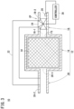
- FIG. 3 is a schematic view showing a configuration of the adjustment device 10 according to a modification.
- the same components as those described in the embodiment are denoted by the same reference numerals. It should be noted that, in the present modification, descriptions that are duplicative of those given in the embodiment will be omitted.
- a bypass conduit 22 a switching device 24, a resistivity meter 26, and a controller 28 are newly provided.
- the bypass conduit 22 is a conduit that is connected to the liquid inflow portion 18 and the liquid outflow portion 20 while bypassing the porous filter 14.
- the switching device 24 is a device that switches the supply destination of the liquid to either the bypass conduit 22 or the porous filter 14.
- the switching device 24 may be a three way valve or two on-off valves.
- the three way valve is provided at a connection portion CP between the bypass conduit 22 and the inlet conduit 18-2 of the liquid inflow portion 18 (see FIG. 3 ).
- the switching device 24 is two on-off valves, one of the two on-off valves is provided in the inlet conduit 18-2 located upstream of the connection portion CP, and the other of the two on-off valves is provided in the bypass conduit 22 near the connection portion CP.
- the resistivity meter 26 measures the resistivity of the liquid supplied to the liquid inflow portion 18.
- the resistivity meter 26 may be provided in the liquid inflow portion 18 or may be provided in the supply source of liquid.
- the supply source of the liquid is a clean water tank.
- the controller 28 controls the switching device 24.
- the controller 28 includes a processor such as a CPU or an MPU, and one or a plurality of memories such as a ROM, a RAM, and a hard disk.
- the controller 28 compares the resistivity of the liquid measured by the resistivity meter 26 with a predetermined threshold. In a case where the resistivity is lower than the predetermined threshold, the controller 28 controls the switching device 24 to switch the supply destination of the liquid to the porous filter 14. On the other hand, in a case where the resistivity is equal to or greater than the predetermined threshold, the controller 28 controls the switching device 24 to switch the supply destination of the liquid to the bypass conduit 22.
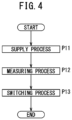
- FIG. 4 is a flowchart showing a flow of an adjustment method according to the modification.
- the adjustment method according to the modification includes a supply process P11, a measuring process P12, and a switching process P13.
- the supply process P11 is a process of supplying a liquid containing metal ions but no solid metal substance to the switching device 24.
- an on-off valve provided in a conduit for guiding the liquid from the supply source of the liquid to the liquid inflow portion 18 of the adjustment device 10 is opened.
- the measuring process P12 is a process of measuring the resistivity of the liquid supplied to the liquid inflow portion 18.
- the resistivity is measured by the resistivity meter 26 provided in the liquid inflow portion 18, the supply source of the liquid, or the like.
- the switching process P13 is a process of switching the supply destination of the liquid to either the bypass conduit 22 or the porous filter 14 based on the measurement result.
- the switching of the supply destination of the liquid is executed by the controller 28. In this process, in a case where the resistivity is lower than the predetermined threshold, the supply destination of the liquid is switched to the porous filter 14. On the other hand, in a case where the resistivity is equal to or greater than the predetermined threshold, the supply destination of the liquid is switched to the bypass conduit 22.
- Each of the supply process P11, the measuring process P12, and the switching process P13 is continued from the start of adjustment of the resistivity of the liquid to the end of the adjustment thereof.
- the liquid can be supplied to the porous filter 14 only when necessary. Therefore, the life time of the porous filter 14 can be increased as compared with a case where the liquid is always supplied to the porous filter 14.
- the resistivity meter 26 of the present modification may be replaced by a conductivity meter.
- the conductivity meter measures the conductivity of the liquid supplied to the liquid inflow portion 18.
- the controller 28 compares the conductivity of the liquid measured by the conductivity meter with a predetermined threshold. In a case where the conductivity exceeds the predetermined threshold, the controller 28 controls the switching device 24 to switch the supply destination of the liquid to the porous filter 14. On the other hand, in a case where the conductivity is equal to or less than the predetermined threshold, the controller 28 controls the switching device 24 to switch the supply destination of the liquid to the bypass conduit 22.
- the filtration filter can be recycled.
Landscapes
- Chemical & Material Sciences (AREA)
- Engineering & Computer Science (AREA)
- Environmental & Geological Engineering (AREA)
- Inorganic Chemistry (AREA)
- Life Sciences & Earth Sciences (AREA)
- Hydrology & Water Resources (AREA)
- Mechanical Engineering (AREA)
- Water Supply & Treatment (AREA)
- Organic Chemistry (AREA)
- Chemical Kinetics & Catalysis (AREA)
- Electrical Discharge Machining, Electrochemical Machining, And Combined Machining (AREA)
- Sampling And Sample Adjustment (AREA)
- Separation Using Semi-Permeable Membranes (AREA)
- Filtering Materials (AREA)
Abstract
Description
- The present invention relates to adjustment of the resistivity of a liquid containing metal ions.
- It is known that there are various fields in which liquids having a low metal ion content are required.
- For example,
JP 2013-132735 A - Further, for example,
JP 2019-098225 A - Further, for example,
JP 2005-213200 A - Furthermore, for example,
JP 2006-095391 A - However, in the case of
JP 2013-132735 A JP 2005-213200 A JP 2019-098225 A - The present invention has the object of solving the aforementioned problem.
- According to a first aspect of the present invention, there is provided an adjustment device that adjusts a resistivity of a liquid containing metal ions but no solid metal substance, the adjustment device comprising: a container including a liquid inflow portion and a liquid outflow portion; and a porous filter accommodated in the container and configured to supply the liquid from the liquid inflow portion to the liquid outflow portion through pores, wherein metal particles in a form of solid are trapped in the pores, and the porous filter makes a resistivity of the liquid after passing through the pores larger than a resistivity of the liquid before passing through the pores.
- According to a second aspect of the present invention, there is provided an adjustment method for adjusting a resistivity of a liquid containing metal ions but no solid metal substance, the adjustment method comprising: causing the liquid to flow through pores of a porous filter in which metal particles in a form of solid are trapped, thereby making a resistivity of the liquid after passing through the pores larger than a resistivity of the liquid before passing through the pores.
- According to a third aspect of the present invention, there is provided a manufacturing method for manufacturing an adjustment device that adjusts a resistivity of a liquid containing metal ions but no solid metal substance, the manufacturing method comprising: a recovery step (P1) of recovering, from a machine tool, a filtration filter configured to remove machining chips generated by machining of a workpiece performed by the machine tool; and an accommodating step (P2) of accommodating the filtration filter in a container including an inlet and an outlet for the liquid.
- According to the above aspects, the metal ion concentration of the liquid can be reduced without using an ion exchange resin or an insolubilizing agent.
-
- [
FIG. 1] FIG. 1 is a schematic view showing a configuration of an adjustment device according to an embodiment; - [
FIG. 2] FIG. 2 is a flowchart showing a flow of a manufacturing method for manufacturing the adjustment device; - [
FIG. 3] FIG. 3 is a schematic view showing a configuration of the adjustment device according to a modification; and - [
FIG. 4] FIG. 4 is a flowchart showing a flow of an adjustment method according to a modification. -
FIG. 1 is a schematic view showing a configuration of anadjustment device 10 according to an embodiment. Theadjustment device 10 includes acontainer 12 and aporous filter 14. - The
container 12 is a receptacle for accommodating theporous filter 14. Thecontainer 12 includes acontainer body portion 16, aliquid inflow portion 18, and aliquid outflow portion 20. - The
container body portion 16 includes a filter accommodation space FS therein. The filter accommodation space FS is a space capable of accommodating theporous filter 14. Thecontainer body portion 16 may include an opening/closing lid for accommodating theporous filter 14 in the filter accommodation space FS. Thecontainer body portion 16 may be separable into a plurality of pieces in order for theporous filter 14 to be accommodated in the filter accommodation space FS. - The
liquid inflow portion 18 communicates with the filter accommodation space FS. Theliquid inflow portion 18 includes an inlet hole 18-1 and an inlet conduit 18-2. The inlet hole 18-1 is a hole that penetrates thecontainer body portion 16 from the outer wall of thecontainer body portion 16 to the inner wall of thecontainer body portion 16. The inlet conduit 18-2 is a conduit pipe that covers the outside of the inlet hole 18-1 and extends outward from the outer wall surface of thecontainer body portion 16. The inlet conduit 18-2 may be formed integrally with thecontainer body portion 16, or may be joined to thecontainer body portion 16 by a joining member. Further, the inlet conduit 18-2 may be removed. - The
liquid outflow portion 20 communicates with the filter accommodation space FS. Theliquid outflow portion 20 includes an outlet hole 20-1 and an outlet conduit 20-2. The outlet hole 20-1 is a hole that penetrates thecontainer body portion 16 from the outer wall of thecontainer body portion 16 to the inner wall of thecontainer body portion 16. The outlet conduit 20-2 is a conduit pipe that covers the outside of the outlet hole 20-1 and extends outward from the outer wall surface of thecontainer body portion 16. The outlet conduit 20-2 may be formed integrally with thecontainer body portion 16, or may be joined to thecontainer body portion 16 by a joining member. Further, the outlet conduit 20-2 may be removed. - The
porous filter 14 is a porous body including pores. Examples of the porous body include filter paper and filter cloth. Solid metal particles are trapped in the pores. The metal particles include at least one of iron, aluminum, copper, zinc, tungsten carbide, tungsten, molybdenum, carbon, titanium, silicon, manganese, chromium, phosphorus, sulfur, and nickel. The metal particles may be machining chips generated by machining of a workpiece performed by a machine tool. When the metal particles are machining chips, theporous filter 14 may be a filtration filter that has been used in the past to remove machining chips generated by machining of the workpiece performed by the machine tool. - The machine tool is a wire electrical discharge machine, a die-sinking electrical discharge machine, a small hole electrical discharge machine, a cutting machine, or the like. The wire electrical discharge machine is a machine that machines a workpiece by electrical discharge generated at a machining gap formed between a wire electrode and the workpiece. The die-sinking electrical discharge machine is a machine that machines a workpiece by electrical discharge generated at a machining gap formed between a die-sinking electrode and the workpiece. The small hole electrical discharge machine is a machine that machines a workpiece by electrical discharge generated at a machining gap formed between a rod electrode having a circular cross section and the workpiece while rotating the rod electrode. The cutting machine is a machine that machines a workpiece using a tool.
- The
porous filter 14 supplies a liquid from theliquid inflow portion 18 to theliquid outflow portion 20 through the pores. In a case where the liquid supplied to theliquid inflow portion 18 contains metal ions but no solid metal substance, the resistivity of the liquid after passing through the pores of theporous filter 14 is larger than the resistivity of the liquid before passing through the pores. - In the adjustment method for the
adjustment device 10, a liquid containing metal ions but no solid metal substance is caused to flow through the pores of theporous filter 14 in which the solid metal particles are trapped, whereby the resistivity of the liquid is increased. - The present inventors have found that, when clean water is caused to pass through the pores of a porous body in which machining chips are trapped, the resistivity of the clean water increases. The machining chips are solid metal particles generated by machining of a workpiece performed by a machine tool. The clean water is a liquid obtained by removing machining chips from a dielectric working fluid, and contains metal ions but no solid metal substance.
- As described above, in the present embodiment, the
porous filter 14 is provided in which solid metal particles are trapped in the pores. Theporous filter 14 makes the resistivity of the liquid containing metal ions but no solid metal substance after passing through the pores larger than that before passing through the pores. This makes it possible to reduce the metal ion concentration of the liquid without using an ion exchange resin or an insolubilizing agent. -
FIG. 2 is a flowchart showing a flow of a manufacturing method for manufacturing theadjustment device 10.FIG. 2 shows a flow of the manufacturing method in a case where a filtration filter that has been used in the past to remove machining chips generated by machining of the workpiece performed by the machine tool is used as theporous filter 14. The manufacturing method for manufacturing theadjustment device 10 includes a recovery process P1 and an accommodating process P2. - The recovery process P1 is a process of recovering the filtration filter from the machine tool. The filtration filter is disposed on a flow path through which wastewater, which is a dielectric working fluid containing machining chips, flows. The filtration filter recovered in the recovery process P1 is a filtration filter that has been used even once (through which wastewater has flowed).
- The accommodating process P2 is a process of accommodating the filtration filter in the
container 12. For example, in a case where thecontainer body portion 16 includes an opening/closing lid, the filtration filter is accommodated in the filter accommodation space FS of thecontainer body portion 16 via the opening/closing lid. Further, for example, in a case where thecontainer body portion 16 is separable into a plurality of pieces, the plurality of pieces are joined together so that the filtration filter is accommodated in the filter accommodation space FS. - According to the manufacturing method described above, the
adjustment device 10 that reduces the metal ion concentration of the liquid without using an ion exchange resin or an insolubilizing agent can be manufactured. Further, the filtration filter can be recycled as theporous filter 14. - The
adjustment device 10 of the present embodiment can be installed in various devices that require a liquid with a low metal ion content. For example, theadjustment device 10 is installed at a necessary location of the wire electrical discharge machine, the water purification system, or the removal device described above. A method for installing theadjustment device 10 will be described by taking a wire electrical discharge machine as an example. - The wire electrical discharge machine includes a conduit for guiding a dielectric working fluid from a clean water tank to a work-pan. The clean water tank is a tank that stores clean water which is the dielectric working fluid from which the machining chips have been removed. The work-pan is a tank that stores a dielectric working fluid for immersing a workpiece. In a case where the
adjustment device 10 is installed in the conduit, for example, the conduit is divided into an upstream portion and a downstream portion. An end portion (a downstream end portion) of the upstream portion is connected to theliquid inflow portion 18 of theadjustment device 10. On the other hand, the downstream portion (an upstream end portion) is connected to theliquid outflow portion 20 of theadjustment device 10. - In a case where the
adjustment device 10 is installed in this manner, theporous filter 14 makes the resistivity of clean water supplied to the work-pan larger than the resistivity of clean water supplied from the clean water tank. Therefore, the metal ion concentration in the dielectric working fluid stored in the work-pan can be reduced without using an ion exchange resin. - The reciprocal of the resistivity [Ωm] is the conductivity [S/m], and there is a correlation between the resistivity [Ωm] and the conductivity [S/m]. Therefore, the resistivity [Ωm] can be replaced with the conductivity [S/m]. When the resistivity [Ωm] is replaced with the conductivity [S/m], the magnitude relationship of the values is reversed. For example, "increasing the resistivity [Ωm]" is synonymous with "decreasing the conductivity [S/m]".
- The above embodiment may be modified as follows.
-
FIG. 3 is a schematic view showing a configuration of theadjustment device 10 according to a modification. InFIG. 3 , the same components as those described in the embodiment are denoted by the same reference numerals. It should be noted that, in the present modification, descriptions that are duplicative of those given in the embodiment will be omitted. - In the present modification, a
bypass conduit 22, aswitching device 24, aresistivity meter 26, and acontroller 28 are newly provided. - The
bypass conduit 22 is a conduit that is connected to theliquid inflow portion 18 and theliquid outflow portion 20 while bypassing theporous filter 14. - The switching
device 24 is a device that switches the supply destination of the liquid to either thebypass conduit 22 or theporous filter 14. The switchingdevice 24 may be a three way valve or two on-off valves. In a case where theswitching device 24 is a three way valve, the three way valve is provided at a connection portion CP between thebypass conduit 22 and the inlet conduit 18-2 of the liquid inflow portion 18 (seeFIG. 3 ). In a case where theswitching device 24 is two on-off valves, one of the two on-off valves is provided in the inlet conduit 18-2 located upstream of the connection portion CP, and the other of the two on-off valves is provided in thebypass conduit 22 near the connection portion CP. - The
resistivity meter 26 measures the resistivity of the liquid supplied to theliquid inflow portion 18. Theresistivity meter 26 may be provided in theliquid inflow portion 18 or may be provided in the supply source of liquid. For example, in a case where theadjustment device 10 is installed in an electrical discharge machine (a wire electrical discharge machine, a die-sinking electrical discharge machine, or a small hole electrical discharge machine), the supply source of the liquid is a clean water tank. - The
controller 28 controls theswitching device 24. Thecontroller 28 includes a processor such as a CPU or an MPU, and one or a plurality of memories such as a ROM, a RAM, and a hard disk. Thecontroller 28 compares the resistivity of the liquid measured by theresistivity meter 26 with a predetermined threshold. In a case where the resistivity is lower than the predetermined threshold, thecontroller 28 controls theswitching device 24 to switch the supply destination of the liquid to theporous filter 14. On the other hand, in a case where the resistivity is equal to or greater than the predetermined threshold, thecontroller 28 controls theswitching device 24 to switch the supply destination of the liquid to thebypass conduit 22. - The adjustment method for the
adjustment device 10 according to the present modification is executed as follows.FIG. 4 is a flowchart showing a flow of an adjustment method according to the modification. The adjustment method according to the modification includes a supply process P11, a measuring process P12, and a switching process P13. - The supply process P11 is a process of supplying a liquid containing metal ions but no solid metal substance to the
switching device 24. In this process, for example, an on-off valve provided in a conduit for guiding the liquid from the supply source of the liquid to theliquid inflow portion 18 of theadjustment device 10 is opened. - The measuring process P12 is a process of measuring the resistivity of the liquid supplied to the
liquid inflow portion 18. The resistivity is measured by theresistivity meter 26 provided in theliquid inflow portion 18, the supply source of the liquid, or the like. - The switching process P13 is a process of switching the supply destination of the liquid to either the
bypass conduit 22 or theporous filter 14 based on the measurement result. The switching of the supply destination of the liquid is executed by thecontroller 28. In this process, in a case where the resistivity is lower than the predetermined threshold, the supply destination of the liquid is switched to theporous filter 14. On the other hand, in a case where the resistivity is equal to or greater than the predetermined threshold, the supply destination of the liquid is switched to thebypass conduit 22. - Each of the supply process P11, the measuring process P12, and the switching process P13 is continued from the start of adjustment of the resistivity of the liquid to the end of the adjustment thereof.
- According to the present modification described above, the liquid can be supplied to the
porous filter 14 only when necessary. Therefore, the life time of theporous filter 14 can be increased as compared with a case where the liquid is always supplied to theporous filter 14. - The
resistivity meter 26 of the present modification may be replaced by a conductivity meter. The conductivity meter measures the conductivity of the liquid supplied to theliquid inflow portion 18. In a case where theresistivity meter 26 is replaced by the conductivity meter, thecontroller 28 compares the conductivity of the liquid measured by the conductivity meter with a predetermined threshold. In a case where the conductivity exceeds the predetermined threshold, thecontroller 28 controls theswitching device 24 to switch the supply destination of the liquid to theporous filter 14. On the other hand, in a case where the conductivity is equal to or less than the predetermined threshold, thecontroller 28 controls theswitching device 24 to switch the supply destination of the liquid to thebypass conduit 22. - The invention and effects that can be grasped from the above description will be described below.
- (1) The present invention is characterized by the adjustment device (10) that adjusts the resistivity of a liquid containing metal ions but no solid metal substance, the adjustment device including: the container (12) including the liquid inflow portion (18) and the liquid outflow portion (20); and the porous filter (14) accommodated in the container and configured to supply the liquid from the liquid inflow portion to the liquid outflow portion through pores, wherein solid metal particles are trapped in the pores, and the porous filter makes the resistivity of the liquid after passing through the pores larger than the resistivity of the liquid before passing through the pores.
According to this feature, it is possible to reduce the metal ion concentration of the liquid without using an ion exchange resin or an insolubilizing agent. - (2) In the adjustment device according to the present invention, the metal particles may include at least one of iron, aluminum, copper, zinc, tungsten carbide, tungsten, molybdenum, carbon, titanium, silicon, manganese, chromium, phosphorus, sulfur, and nickel. According to this feature, it is possible to appropriately increase the resistivity of the liquid containing metal ions but no solid metal substance.
- (3) In the adjustment device according to the present invention, the metal particles may be machining chips generated by machining of the workpiece performed by the machine tool. According to this feature, it is possible to appropriately increase the resistivity of the liquid containing metal ions but no solid metal substance.
- (4) In the adjustment device according to the present invention, the porous filter may be a filter that has been used in the past as a filtration filter configured to remove machining chips generated by machining of the workpiece performed by the machine tool. According to this feature, the filtration filter can be recycled.
- (5) The adjustment device according to the present invention may further include: the bypass conduit (22) connected to the liquid inflow portion and the liquid outflow portion while bypassing the porous filter; the switching device (24) configured to switch the supply destination of the liquid to either the bypass conduit or the porous filter; the resistivity meter (26) configured to measure the resistivity of the liquid supplied to the liquid inflow portion; and the controller (28) configured to control the switching device to switch the supply destination of the liquid to the porous filter in a case where the resistivity of the liquid is lower than the predetermined threshold, and control the switching device to switch the supply destination of the liquid to the bypass conduit in a case where the resistivity of the liquid is equal to or greater than the predetermined threshold. According to this feature, the liquid can be supplied to the porous filter only when necessary. Therefore, the life time of the porous filter can be increased as compared with a case where the liquid is always supplied to the porous filter.
- (6) The present invention is characterized by the adjustment method for adjusting the resistivity of a liquid containing metal ions but no solid metal substance, the adjustment method including: causing the liquid to flow through pores of the porous filter in which solid metal particles are trapped, thereby making the resistivity of the liquid after passing through the pores larger than the resistivity of the liquid before passing through the pores.
According to this feature, it is possible to reduce the metal ion concentration of the liquid without using an ion exchange resin or an insolubilizing agent. - (7) The adjustment method according to the present invention may further include: the measuring step (P12) of measuring the resistivity of the liquid supplied to the porous filter; and the switching step (P13) of, based on the measurement result, switching the supply destination of the liquid to either the porous filter or the bypass conduit bypassing the porous filter, wherein, in the switching step, the supply destination of the liquid may be switched to the porous filter in a case where the resistivity of the liquid is lower than the predetermined threshold, and the supply destination of the liquid may be switched to the bypass conduit in a case where the resistivity of the liquid is equal to or greater than the predetermined threshold. According to this feature, the liquid can be supplied to the porous filter only when necessary. Therefore, the life time of the porous filter can be increased as compared with a case where the liquid is always supplied to the porous filter.
- (8) The present invention is characterized by the manufacturing method for manufacturing the adjustment device that adjusts the resistivity of a liquid containing metal ions but no solid metal substance, the manufacturing method including: the recovery step (P1) of recovering, from the machine tool, the filtration filter configured to remove machining chips generated by machining of the workpiece performed by the machine tool; and the accommodating step (P2) of accommodating the filtration filter in the container including the inlet and the outlet for the liquid.
- According to this feature, it is possible to reduce the metal ion concentration of the liquid without using an ion exchange resin or an insolubilizing agent. Further, the filtration filter can be recycled.
- The present invention is not limited to the above disclosure, and various modifications are possible without departing from the essence and gist of the present invention.
-
- 10:
- adjustment device
- 12:
- container
- 14:
- porous filter
- 16:
- container body portion
- 18:
- liquid inflow portion
- 20:
- liquid outflow portion
- 22:
- bypass conduit
- 24:
- switching device
- 26:
- resistivity meter
- 28:
- controller
Claims (8)
- An adjustment device (10) that adjusts a resistivity of a liquid containing metal ions but no solid metal substance, the adjustment device comprising:a container (12) including a liquid inflow portion (18) and a liquid outflow portion (20); anda porous filter (14) accommodated in the container and configured to supply the liquid from the liquid inflow portion to the liquid outflow portion through pores,wherein metal particles in a form of solid are trapped in the pores, andthe porous filter makes a resistivity of the liquid after passing through the pores larger than a resistivity of the liquid before passing through the pores.
- The adjustment device according to claim 1, wherein
the metal particles include at least one of iron, aluminum, copper, zinc, tungsten carbide, tungsten, molybdenum, carbon, titanium, silicon, manganese, chromium, phosphorus, sulfur, and nickel. - The adjustment device according to claim 1 or 2, wherein
the metal particles are machining chips generated by machining of a workpiece performed by a machine tool. - The adjustment device according to any one of claims 1 to 3, wherein
the porous filter is a filter that has been used in a past as a filtration filter configured to remove machining chips generated by machining of a workpiece performed by a machine tool. - The adjustment device according to any one of claims 1 to 4, further comprising:a bypass conduit (22) connected to the liquid inflow portion and the liquid outflow portion while bypassing the porous filter;a switching device (24) configured to switch a supply destination of the liquid to either the bypass conduit or the porous filter;a resistivity meter (26) configured to measure a resistivity of the liquid supplied to the liquid inflow portion; anda controller (28) configured to control the switching device to switch the supply destination of the liquid to the porous filter in a case where the resistivity of the liquid is lower than a predetermined threshold, and control the switching device to switch the supply destination of the liquid to the bypass conduit in a case where the resistivity of the liquid is equal to or greater than the predetermined threshold.
- An adjustment method for adjusting a resistivity of a liquid containing metal ions but no solid metal substance, the adjustment method comprising:
causing the liquid to flow through pores of a porous filter in which metal particles in a form of solid are trapped, thereby making a resistivity of the liquid after passing through the pores larger than a resistivity of the liquid before passing through the pores. - The adjustment method according to claim 6, further comprising:a measuring step (P12) of measuring a resistivity of the liquid supplied to the porous filter; and a switching step (P13) of, based on a measurement result, switching a supply destination of the liquid to either the porous filter or a bypass conduit bypassing the porous filter, whereinin the switching step,the supply destination of the liquid is switched to the porous filter in a case where the resistivity of the liquid is lower than a predetermined threshold, and the supply destination of the liquid is switched to the bypass conduit in a case where the resistivity of the liquid is equal to or greater than the predetermined threshold.
- A manufacturing method for manufacturing an adjustment device that adjusts a resistivity of a liquid containing metal ions but no solid metal substance, the manufacturing method comprising:a recovery step (P1) of recovering, from a machine tool, a filtration filter configured to remove machining chips generated by machining of a workpiece performed by the machine tool; andan accommodating step (P2) of accommodating the filtration filter in a container including an inlet and an outlet for the liquid.
Applications Claiming Priority (1)
| Application Number | Priority Date | Filing Date | Title |
|---|---|---|---|
| PCT/JP2022/025145 WO2023248435A1 (en) | 2022-06-23 | 2022-06-23 | Adjustment device, adjustment method, and manufacturing method |
Publications (2)
| Publication Number | Publication Date |
|---|---|
| EP4545495A1 true EP4545495A1 (en) | 2025-04-30 |
| EP4545495A4 EP4545495A4 (en) | 2026-04-22 |
Family
ID=89379315
Family Applications (1)
| Application Number | Title | Priority Date | Filing Date |
|---|---|---|---|
| EP22947996.9A Pending EP4545495A4 (en) | 2022-06-23 | 2022-06-23 | ADJUSTING DEVICE, ADJUSTING PROCEDURE AND MANUFACTURING PROCEDURE |
Country Status (5)
| Country | Link |
|---|---|
| EP (1) | EP4545495A4 (en) |
| JP (1) | JPWO2023248435A1 (en) |
| CN (1) | CN119365422A (en) |
| TW (1) | TW202406612A (en) |
| WO (1) | WO2023248435A1 (en) |
Family Cites Families (11)
| Publication number | Priority date | Publication date | Assignee | Title |
|---|---|---|---|---|
| JP2005213200A (en) | 2004-01-29 | 2005-08-11 | Mitsui Chemicals Inc | Method for removing metal compound from nonionic surfactant, metal compound removal apparatus and use thereof |
| JP2006095391A (en) | 2004-09-28 | 2006-04-13 | Ebara Corp | Apparatus and method for treating waste water |
| US7737380B2 (en) * | 2005-05-23 | 2010-06-15 | Mitsubishi Electric Corporation | Electrical-discharge machining apparatus and method and apparatus for dielectric-fluid quality control |
| CN201040207Y (en) * | 2007-05-17 | 2008-03-26 | 李立功 | Wastewater filter |
| CA2684298A1 (en) * | 2007-04-18 | 2008-10-30 | H2Q Water Industries Ltd. | Filter medium |
| JP2013132735A (en) | 2011-12-27 | 2013-07-08 | Fanuc Ltd | Wire electric discharge machine dissolving inert gas in machining fluid and wire electric discharge machining method |
| US9339882B2 (en) * | 2012-07-02 | 2016-05-17 | Mitsubishi Electric Corporation | Cleaning device for electrical-discharge machining fluid and cleaning method for electrical-discharge machining fluid |
| JP2015155085A (en) * | 2014-02-20 | 2015-08-27 | 株式会社トクシン電気 | impurities removal system |
| TWM483119U (en) * | 2014-03-28 | 2014-08-01 | Jia Li Entpr Co Ltd | Filter device capable of detecting water quality |
| JP6407922B2 (en) * | 2016-07-21 | 2018-10-17 | ファナック株式会社 | Wire electric discharge machine |
| JP2019098225A (en) | 2017-11-30 | 2019-06-24 | パナソニックIpマネジメント株式会社 | Water purification system |
-
2022
- 2022-06-23 JP JP2024528216A patent/JPWO2023248435A1/ja active Pending
- 2022-06-23 WO PCT/JP2022/025145 patent/WO2023248435A1/en not_active Ceased
- 2022-06-23 EP EP22947996.9A patent/EP4545495A4/en active Pending
- 2022-06-23 CN CN202280097144.6A patent/CN119365422A/en active Pending
-
2023
- 2023-06-20 TW TW112123020A patent/TW202406612A/en unknown
Also Published As
| Publication number | Publication date |
|---|---|
| CN119365422A (en) | 2025-01-24 |
| WO2023248435A1 (en) | 2023-12-28 |
| EP4545495A4 (en) | 2026-04-22 |
| JPWO2023248435A1 (en) | 2023-12-28 |
| TW202406612A (en) | 2024-02-16 |
Similar Documents
| Publication | Publication Date | Title |
|---|---|---|
| KR100498152B1 (en) | Electrowinning cell incorporating metal ion filtration apparatus | |
| JP2005219201A (en) | Liquid treatment system for wire cut electrical discharge machining | |
| WO2023248435A1 (en) | Adjustment device, adjustment method, and manufacturing method | |
| KR101910853B1 (en) | Apparatus for flushing reduced type waste water of plating process | |
| JP2019141929A (en) | Electric discharge machine | |
| WO2023248434A1 (en) | Electrical discharge machine | |
| JP5005165B2 (en) | Water treatment method | |
| EP2347849A1 (en) | Method for recovering corrosion preventive agent in electrodischarge machining liquid supply apparatus | |
| JP2012115816A (en) | Apparatus and method for treating sludge | |
| JPH0112920Y2 (en) | ||
| JP7244896B2 (en) | CMP slurry regeneration method | |
| JP5493841B2 (en) | Electrolytic processing equipment | |
| KR102866793B1 (en) | System for treatment waste cutting oil | |
| JPWO2023248435A5 (en) | ||
| JPH0429745B2 (en) | ||
| EP4631659A1 (en) | Device for treating water for machining | |
| JP2012115800A (en) | Sludge dehydrator and method for dehydrating sludge | |
| EP0442119B1 (en) | Method and apparatus for treating the dielectric used in electrical discharge machining | |
| JP2018034119A (en) | Separation device for separating and recovering specific chemical substance from contaminated liquid contaminated by specific chemical substance | |
| EP4365141A1 (en) | Upflow electrochemical coagulation reactor and method of removing contaminant from wastewater using same | |
| JPWO2023248434A5 (en) | ||
| JP3116852U (en) | Antifreeze volume reduction treatment equipment | |
| JP2026008822A (en) | filtration device | |
| Valenti | Metalworkers clean up their waste | |
| JP2007105863A (en) | EDM machine |
Legal Events
| Date | Code | Title | Description |
|---|---|---|---|
| STAA | Information on the status of an ep patent application or granted ep patent |
Free format text: STATUS: THE INTERNATIONAL PUBLICATION HAS BEEN MADE |
|
| PUAI | Public reference made under article 153(3) epc to a published international application that has entered the european phase |
Free format text: ORIGINAL CODE: 0009012 |
|
| STAA | Information on the status of an ep patent application or granted ep patent |
Free format text: STATUS: REQUEST FOR EXAMINATION WAS MADE |
|
| 17P | Request for examination filed |
Effective date: 20241213 |
|
| AK | Designated contracting states |
Kind code of ref document: A1 Designated state(s): AL AT BE BG CH CY CZ DE DK EE ES FI FR GB GR HR HU IE IS IT LI LT LU LV MC MK MT NL NO PL PT RO RS SE SI SK SM TR |
|
| DAV | Request for validation of the european patent (deleted) | ||
| DAX | Request for extension of the european patent (deleted) | ||
| REG | Reference to a national code |
Ref country code: DE Ref legal event code: R079 Free format text: PREVIOUS MAIN CLASS: C02F0001580000 Ipc: C02F0001280000 |
|
| A4 | Supplementary search report drawn up and despatched |
Effective date: 20260319 |
|
| RIC1 | Information provided on ipc code assigned before grant |
Ipc: C02F 1/28 20230101AFI20260313BHEP Ipc: C02F 1/00 20230101ALN20260313BHEP Ipc: C02F 101/20 20060101ALN20260313BHEP Ipc: C02F 103/16 20060101ALN20260313BHEP |