EP4545475A1 - Insulated telescopic arm and insulated bucket arm vehicle - Google Patents
Insulated telescopic arm and insulated bucket arm vehicle Download PDFInfo
- Publication number
- EP4545475A1 EP4545475A1 EP23856095.7A EP23856095A EP4545475A1 EP 4545475 A1 EP4545475 A1 EP 4545475A1 EP 23856095 A EP23856095 A EP 23856095A EP 4545475 A1 EP4545475 A1 EP 4545475A1
- Authority
- EP
- European Patent Office
- Prior art keywords
- arm
- insulated
- roller
- piston
- outer arm
- Prior art date
- Legal status (The legal status is an assumption and is not a legal conclusion. Google has not performed a legal analysis and makes no representation as to the accuracy of the status listed.)
- Pending
Links
Images


Classifications
-
- B—PERFORMING OPERATIONS; TRANSPORTING
- B66—HOISTING; LIFTING; HAULING
- B66F—HOISTING, LIFTING, HAULING OR PUSHING, NOT OTHERWISE PROVIDED FOR, e.g. DEVICES WHICH APPLY A LIFTING OR PUSHING FORCE DIRECTLY TO THE SURFACE OF A LOAD
- B66F11/00—Lifting devices specially adapted for particular uses not otherwise provided for
- B66F11/04—Lifting devices specially adapted for particular uses not otherwise provided for for movable platforms or cabins, e.g. on vehicles, permitting workmen to place themselves in any desired position for carrying out required operations
- B66F11/044—Working platforms suspended from booms
- B66F11/046—Working platforms suspended from booms of the telescoping type
-
- B—PERFORMING OPERATIONS; TRANSPORTING
- B66—HOISTING; LIFTING; HAULING
- B66F—HOISTING, LIFTING, HAULING OR PUSHING, NOT OTHERWISE PROVIDED FOR, e.g. DEVICES WHICH APPLY A LIFTING OR PUSHING FORCE DIRECTLY TO THE SURFACE OF A LOAD
- B66F13/00—Common constructional features or accessories
-
- B—PERFORMING OPERATIONS; TRANSPORTING
- B66—HOISTING; LIFTING; HAULING
- B66C—CRANES; LOAD-ENGAGING ELEMENTS OR DEVICES FOR CRANES, CAPSTANS, WINCHES, OR TACKLES
- B66C23/00—Cranes comprising essentially a beam, boom, or triangular structure acting as a cantilever and mounted for translatory of swinging movements in vertical or horizontal planes or a combination of such movements, e.g. jib-cranes, derricks, tower cranes
- B66C23/62—Constructional features or details
- B66C23/64—Jibs
- B66C23/70—Jibs constructed of sections adapted to be assembled to form jibs or various lengths
- B66C23/701—Jibs constructed of sections adapted to be assembled to form jibs or various lengths telescopic
- B66C23/707—Jibs constructed of sections adapted to be assembled to form jibs or various lengths telescopic guiding devices for telescopic jibs
-
- B—PERFORMING OPERATIONS; TRANSPORTING
- B66—HOISTING; LIFTING; HAULING
- B66F—HOISTING, LIFTING, HAULING OR PUSHING, NOT OTHERWISE PROVIDED FOR, e.g. DEVICES WHICH APPLY A LIFTING OR PUSHING FORCE DIRECTLY TO THE SURFACE OF A LOAD
- B66F11/00—Lifting devices specially adapted for particular uses not otherwise provided for
- B66F11/04—Lifting devices specially adapted for particular uses not otherwise provided for for movable platforms or cabins, e.g. on vehicles, permitting workmen to place themselves in any desired position for carrying out required operations
-
- B—PERFORMING OPERATIONS; TRANSPORTING
- B66—HOISTING; LIFTING; HAULING
- B66F—HOISTING, LIFTING, HAULING OR PUSHING, NOT OTHERWISE PROVIDED FOR, e.g. DEVICES WHICH APPLY A LIFTING OR PUSHING FORCE DIRECTLY TO THE SURFACE OF A LOAD
- B66F17/00—Safety devices, e.g. for limiting or indicating lifting force
- B66F17/006—Safety devices, e.g. for limiting or indicating lifting force for working platforms
-
- E—FIXED CONSTRUCTIONS
- E02—HYDRAULIC ENGINEERING; FOUNDATIONS; SOIL SHIFTING
- E02F—DREDGING; SOIL-SHIFTING
- E02F3/00—Dredgers; Soil-shifting machines
- E02F3/04—Dredgers; Soil-shifting machines mechanically-driven
- E02F3/28—Dredgers; Soil-shifting machines mechanically-driven with digging tools mounted on a dipper- or bucket-arm, i.e. there is either one arm or a pair of arms, e.g. dippers, buckets
- E02F3/30—Dredgers; Soil-shifting machines mechanically-driven with digging tools mounted on a dipper- or bucket-arm, i.e. there is either one arm or a pair of arms, e.g. dippers, buckets with a dipper-arm pivoted on a cantilever beam, i.e. boom
- E02F3/306—Dredgers; Soil-shifting machines mechanically-driven with digging tools mounted on a dipper- or bucket-arm, i.e. there is either one arm or a pair of arms, e.g. dippers, buckets with a dipper-arm pivoted on a cantilever beam, i.e. boom with telescopic dipper-arm or boom
-
- F—MECHANICAL ENGINEERING; LIGHTING; HEATING; WEAPONS; BLASTING
- F16—ENGINEERING ELEMENTS AND UNITS; GENERAL MEASURES FOR PRODUCING AND MAINTAINING EFFECTIVE FUNCTIONING OF MACHINES OR INSTALLATIONS; THERMAL INSULATION IN GENERAL
- F16B—DEVICES FOR FASTENING OR SECURING CONSTRUCTIONAL ELEMENTS OR MACHINE PARTS TOGETHER, e.g. NAILS, BOLTS, CIRCLIPS, CLAMPS, CLIPS OR WEDGES; JOINTS OR JOINTING
- F16B7/00—Connections of rods or tubes, e.g. of non-circular section, mutually, including resilient connections
- F16B7/10—Telescoping systems
-
- F—MECHANICAL ENGINEERING; LIGHTING; HEATING; WEAPONS; BLASTING
- F16—ENGINEERING ELEMENTS AND UNITS; GENERAL MEASURES FOR PRODUCING AND MAINTAINING EFFECTIVE FUNCTIONING OF MACHINES OR INSTALLATIONS; THERMAL INSULATION IN GENERAL
- F16C—SHAFTS; FLEXIBLE SHAFTS; ELEMENTS OR CRANKSHAFT MECHANISMS; ROTARY BODIES OTHER THAN GEARING ELEMENTS; BEARINGS
- F16C29/00—Bearings for parts moving only linearly
- F16C29/04—Ball or roller bearings
- F16C29/045—Ball or roller bearings having rolling elements journaled in one of the moving parts
Definitions
- the present disclosure belongs to the technical field of engineering machinery, and particularly relates to an insulated telescopic arm and an insulated bucket arm vehicle.
- Insulated bucket arm vehicles are aerial live working apparatuses, which have characteristics of convenient lifting, high mobility, high stability, and high insulating property, and are favored in the power industry.
- the insulated telescopic arms of existing insulated bucket arm vehicles are usually of a slider type, which is to say, a nylon slider is mounted on the inner lower surface of an outer arm, the outer lower surface of the inner arm made of glass fiber reinforced plastics (FRP) contacts with the nylon slider in the extension and retraction process of the FRP inner arm, thereby a sliding movement is produced, so as to avoid direct contact between the FRP inner arm and the iron outer arm.
- a slider type which is to say, a nylon slider is mounted on the inner lower surface of an outer arm, the outer lower surface of the inner arm made of glass fiber reinforced plastics (FRP) contacts with the nylon slider in the extension and retraction process of the FRP inner arm, thereby a sliding movement is produced, so as to avoid direct contact between the FRP inner arm and the iron outer arm.
- FRP glass fiber reinforced plastics
- nylon tends to be aged and is not wear-resistant; and the sliding friction resistance will increase as long as the surface is slightly damaged, indirectly resulting in increased pressure of the hydraulic system; consequently, the telescopic arm is forced to extend, and the friction between the FRP inner arm and the nylon slider causes scratches on the insulating coating on the FRP outer surface, which lead to degraded insulation of the FRP inner arm and potential safety hazards.
- the system pressure is high, the hydraulic oil temperature will rise rapidly, the service life of the hydraulic oil will be shortened, and impacts on the sealing elements in the hydraulic system will occur, increasing the probability of damage of the sealing elements and increasing the possibility of oil leakage.
- a rolling roller device for insulated arms is disclosed in Chinese Utility Model No. 201120564104.7 .
- the rolling roller device includes a basic arm and an insulated telescopic arm limited inside the basic arm, and a rolling shaft is arranged below the insulated telescopic arm.
- the rolling roller device can be used in replacement of an existing slider, so as to produce rolling friction between the arms, thereby decrease the pressure of the hydraulic system and reduce the wear on the insulated arm.
- the contact area between the insulated telescopic arm and the rolling roller device is significantly smaller than the contact area between the insulated telescopic arm and the slider.
- China Utility Model No. 201621407892.8 provides a roller mechanism for the telescopic arm of a hybrid-arm insulated aerial device, in which two rollers are mounted in parallel to form an integral roller assembly, and, when the FRP inner arm extends and is bent to a certain degree, the roller mechanism will adjust automatically according to the bending condition of the FRP inner arm, so that the inner arm is in full contact with the roller mechanism to ensure the rolling effect.
- this scheme only allows the two rollers to share the pressure, but can't ensure that the two rollers bear the pressure evenly; as a result, the FRP inner arm may be worn easily, and the service life and insulated performance of the FRP inner arm are affected adversely.
- the present disclosure provides an insulated telescopic arm and an insulated bucket arm vehicle, so as to solve the technical problem that two rollers used in parallel to form an integral roller assembly can share the pressure of the insulated inner arm but may not bear the pressure evenly.
- an insulated telescopic arm which includes: an outer arm, an insulated inner arm and a self-adjusting roller apparatus, the insulated inner arm is confined in the outer arm and can move and extend from a free end of the outer arm in an axial direction;
- the self-adjusting roller apparatus includes a pressure cylinder arranged on the outer arm, piston rods that can move up and down in the pressure cylinder, and roller assemblies for bearing the insulated inner arm, at least two roller assemblies are provided, and each roller assembly includes a roller shaft and a roller body that is used for bearing the insulated inner arm and is rotatably sleeved outside the roller shaft, and two ends of the roller shaft extending out of the roller body are correspondingly connected to the piston rods.
- the pressure cylinder includes a cylinder body with a communication space formed therein and a piston lifting portion with a lifting channel formed therein, the cylinder body is provided with piston lifting portions respectively arranged at positions corresponding to the two ends of the roller assembly, and the communication space of the cylinder body is in communication with the lifting channels of the piston lifting portions; and the piston rod includes a piston body arranged in the lifting channel and a rod body connecting the piston body and the roller shaft.
- each piston rod is provided with a movement hole
- the self-adjusting roller apparatus further includes retaining nuts; two ends of the roller shaft extending out of the roller body pass through corresponding movement holes and retaining nuts, and are connected to the retaining nuts through threads.
- the movement hole is formed with a movement clearance for the roller shaft to move up and down.
- the roller shaft has a circular cross section, and the movement hole is a square hole.
- a bearing element is arranged between the roller shaft and the roller body.
- a lower side plate of the outer arm bulges downward to form a mounting space for accommodating the pressure cylinder.
- the insulated telescopic arm further includes a first stop block, which is arranged on the inner wall of the outer arm and used for abutting against the upper side and the left and right sides of the insulated inner arm.
- the insulated telescopic arm further includes a second stop block, which is arranged on the outer peripheral wall of the inner end of the insulated inner arm and used for abutting against the inner wall of the outer arm.
- a plurality of roller assemblies are provided, each roller assembly is arranged in the width direction of the outer arm, and the plurality of roller assemblies are arranged at an interval sequentially in the length direction of the outer arm.
- the present disclosure further provides an insulated bucket arm vehicle, which includes the insulated telescopic arm described above.
- the insulated telescopic arm provided in the embodiments of the present disclosure achieves the following beneficial effects:
- the self-adjusting roller apparatus includes a pressure cylinder arranged on the outer arm, piston rods that can move up and down in the pressure cylinder and roller assemblies for bearing the insulated inner arm, and at least two roller assemblies are provided, at least two roller assemblies can respectively support the insulated inner arm in a rolling state during a telescopic operation of the insulated inner arm, and each roller assembly includes a roller shaft and a roller body that is used for bearing the insulated inner arm and rotatably sleeved outside the roller shaft; two ends of the roller shaft extending out of the roller body are correspondingly connected with the piston rods, i.e., each roller assembly is correspondingly connected with two piston rods to support the two ends of the roller assembly respectively; thus, when the insulated inner arm extends out of the free end of the outer arm and is bent to a certain degree, the piston rod
- an insulated telescopic arm which includes:
- the self-adjusting roller apparatus 3 includes a pressure cylinder 31 arranged on the outer arm 1, piston rods 32 that can move up and down in the pressure cylinder 31 and roller assemblies 33 for bearing the insulated inner arm 2, and at least two roller assemblies 33 are provided, at least two roller assemblies 33 can support the insulated inner arm 2 respectively during the telescopic operation of the insulated inner arm 2; in addition, the roller assembly 33 includes a roller shaft 331 and a roller body 332 that is used for bearing the insulated inner arm 2 and is rotatably sleeved outside the roller shaft 331, and two ends of the roller shaft 331 extending out of the roller body 332 are correspondingly connected to the piston rods 32, i.e., each roller assembly 33 is correspondingly connected to two piston rods 32 to support the two ends of the roller assembly 33 respectively.
- the piston rods 32 at the two ends of at least two roller assemblies 33 can move up and down in the pressure cylinder 31 according to the bending condition of the insulated inner arm 2, so as to realize automatic adjustment, and the at least two roller assemblies 33 are in full contact with the insulated inner arm 2 to ensure a rolling effect; in addition, owing to the fact that the fluid medium in the pressure cylinder 31 exerts equal pressure on each piston rod 32, the at least two roller assemblies 33 bear the pressure evenly, thereby the wear rate is greatly reduced, and the service life and insulated performance of the insulated inner arm 2 are improved.
- the insulated telescopic arm provided by the present disclosure can also solve the technical problem of uneven pressure on the left and right ends of the roller assemblies 33.
- the number of the roller assemblies 33 may be n (n is greater than or equal to 2); in that case, when the piston rods 32 at the two ends of each roller assembly 33 are placed in the pressure cylinder 31, a hydraulic system with 2n piston rods 32 can be formed.
- Pascal's law in engineering hydromechanics after the specific pressure at any point in an incompressible static fluid is increased as a result of an external force, the increased specific pressure is instantaneously transferred to all points in the static fluid. That is to say, when certain specific pressure is applied on one piston rod 32 in a hydraulic system, the same increased specific pressure will be generated on the other piston rods 32.
- the outer arm 1 in the present disclosure may be a metal outer arm or an insulated outer arm, which may be selected according to the actual situation.
- the pressure cylinder 31 in the present disclosure may be a hydraulic cylinder or a pneumatic cylinder; in the case of a hydraulic cylinder, the fluid medium in the hydraulic cylinder may include but is not limited to hydraulic oil; in the case of a pneumatic cylinder, the fluid medium in the pneumatic cylinder may include but is not limited to air.
- the cylinder body 311 may be provided with piston lifting portions 312 in quantity equal to two times of the quantity of the roller assemblies 33, in order to correspond to the two ends of each roller assembly 33 in the at least two roller assemblies 33, and the lifting channel 314 of each piston lifting portion 312 is in communication with the communication space 313 of the cylinder body 311, so that the fluid medium in the communication space 313 can be injected into each lifting channel 314 respectively.
- each piston rod 32 includes a piston body 321 arranged in the lifting channel 314 and a rod body 322 connecting the piston body 321 and the roller shaft 331, the piston body 321 is arranged in close fit with the peripheral wall of the lifting channel 314, and the rod body 322 is connected to the end of the roller shaft 331 extending out of the roller body 332.
- the piston body 321 can divide the lifting channel 314 into two parts, specifically, one part of the lifting channel 314 below the piston body 321 is in communication with the communication space 313 and can be filled with the fluid medium, while the other part of the lifting channel 314 above the piston body 321 is blocked from communicating with the communication space 313 owing to the sealing effect of the piston body 321, so that the fluid medium can't enter the part of the lifting channel 314 above the piston body 321.
- the arrangement of the lifting channels 314 can ensure the stability of the up-and-down movement of the piston rod 32, and the communication space 313 can communicate with the lifting channels 314, so that each piston body 321 can bear the same acting force.
- the number of the piston lifting portions 312 of the pressure cylinder 31 is 2n, which is to say, the number of the lifting channels 314 is 2n, the 2n lifting channels 314 can be in communication with each other via the communication space 313 of the cylinder body 311, and the 2n piston lifting portions 312 are respectively arranged in one-to-one correspondence with the two ends of the n roller assemblies 33.
- the piston bodies 321 with 2n piston rods 32 are arranged in 2n lifting channels 314 in one-to-one correspondence, and are respectively connected to the ends of the corresponding roller shafts 331 extending out of the roller body 332 via the rod bodies 322.
- the piston rod 32 is provided with a movement hole 323, and the self-adjusting roller apparatus 3 further includes retaining nuts 34.
- the two ends of the roller shaft 331 extending out of the roller body 332 pass through the corresponding movement hole 323 and the retaining nuts 34 sequentially, and are connected with the retaining nuts 34 through threads.
- the piston rod 32 may be provided with a movement hole 323 for the roller shaft 331 to pass there-through, an end of the roller shaft 331 passing through the movement hole 323 is provided with an external threaded section, and a retaining nut 34 is sleeved on the external threaded section to limit the axial movement of the roller shaft 331; moreover, the two ends of the roller shaft 331 of each roller assembly 33 are correspondingly provided with a piston rod 32 and a retaining nut 34, so that the two ends of the roller assembly 33 can be connected to two piston rods 32 respectively.
- Each piston rod 32 is detachably connected with the roller assembly 33 to facilitate maintenance and service. As shown in Fig.
- the movement hole 323 is formed with a movement clearance 324 for the roller shaft 331 to move up and down.
- the piston rod 32 is connected to the roller shaft 331 through the movement hole 323, and the diameter of the movement hole 323 in the height direction is greater than the shaft diameter of the roller shaft 331, so that when the roller shaft 331 is inserted through the movement hole 323, a movement clearance 324 exists in the movement hole 323 for the roller shaft 331 to move up and down; thus, when the insulated inner arm 2 extends out and bears an offset load, the two ends of the roller shaft 331 can be adjusted adaptively in the corresponding movement hole 323, as shown in Fig. 7 .
- the roller shaft 331 may have a circular cross section, and the movement hole 323 may be a square hole.
- the distance between the upper inner wall and the lower inner wall of the movement hole 323 configured as a square hole may be greater than the diameter of the circular cross section of the roller shaft 331.
- a bearing element may be provided between the roller shaft 331 and the roller body 332.
- the roller body 332 can roll with minimal friction.
- two bearing elements are provided, and the two bearing elements are arranged at two ends on the inner side of the roller body 332, so that the roller body 332 can be supported from the two ends.
- a lower side plate of the outer arm 1 bulges downward to form a mounting space 11 for accommodating the pressure cylinder 31, so as to minimize the size of the outer arm 1.
- the outer arm 1 includes an upper side plate and a lower side plate that are oppositely arranged, and a left side plate and a right side plate that are oppositely arranged, and the mounting space 11 may be arranged near the free end of the outer arm 1.
- the insulated telescopic arm further includes a first stop block 12, which is arranged on the inner wall of the outer arm 1 and used for abutting against the upper side and the left and right sides of the insulated inner arm 2. That is to say, the first stop block 12 arranged on the outer arm 1 cooperates with the self-adjusting roller apparatus 3 to limit the insulated inner arm 2 from the periphery of the insulated inner arm 2, so that the insulated inner arm 2 can be accurately centered during the telescopic operation.
- first stop blocks 12 may be provided, and the three first stop blocks 12 are respectively arranged on the inner walls of the upper side plate, the left side plate and the right side plate of the outer arm 1 corresponding to the self-adjusting roller apparatus 3.
- the present disclosure is not limited to that arrangement.
- the first stop block 12 may be designed into an integral structure, and may be arranged on the inner walls of the left side plate, the upper side plate and the right side plate of the outer arm 1 sequentially.
- first stop block 12 may be mounted to the outer arm 1 by means of threaded fasteners, and the first stop block 12 may be made of nylon or rubber.
- the insulated telescopic arm further includes a second stop block 21, which is arranged on the outer peripheral wall of the inner end of the insulated inner arm 2 and used for abutting against the inner wall of the outer arm 1. That is to say, the second stop block 21 arranged on the insulated inner arm 2 can limit the insulated inner arm 2 from the periphery of the insulated inner arm 2 at the inner end of the insulated inner arm 2, so as to further ensure that the insulated inner arm 2 can be accurately centered during the telescopic operation.
- second stop blocks 21 may be provided, and the four second stop blocks 21 may be respectively arranged on the outer peripheral wall of the insulated inner arm 2 and respectively abut against the inner walls of the upper side plate, the lower side plate, the left side plate and the right side plate of the outer arm 1 in one-to-one correspondence.
- the present disclosure is not limited to that arrangement.
- the second stop block 21 may be designed into an integral structure, and may be arranged around the outer peripheral wall of the inner end of the insulated inner arm 2. It may be noted particularly that the inner end of the insulated inner arm 2 is referred in relation to the outer end of the insulated inner arm 2.
- a plurality of roller assemblies 33 are provided, each roller assembly 33 extends in the width direction of the outer arm 1, and the plurality of roller assemblies 33 are sequentially arranged at an interval in the length direction of the outer arm 1.
- the number of the roller assemblies 33 may be more than two or even up to ten, and may be determined according to the actual requirement.
- each of the plurality of roller assemblies 33 can be connected with a piston rod 32 that can move up and down in the pressure cylinder 31, the plurality of roller assemblies 33 bear the pressure evenly; in addition, as the number of the roller assemblies 33 is increased, the pressure evenly exerted on each roller assembly 33 by the insulated inner arm 2 can be decreased, so as to further attain the purpose of reducing wear.
- first and second are used only for a descriptive purpose, but shall not be interpreted as indicating or implying relative importance or implicitly indicating the quantity of the indicated technical features. Hence, a feature defined by “first” or “second” may explicitly or implicitly include at least one such feature. In the description of the present disclosure, "a plurality” means at least two, such as two or more, etc., unless otherwise specified explicitly.
- connection may be a fixed connection, a detachable connection, or an integral connection; may be a mechanical connection or an electrical connection or in communication with each other; may be a direct connection or an indirect connection via an intermediate medium, or internal communication or interactive relation between two elements.
- install may be a fixed connection, a detachable connection, or an integral connection; may be a mechanical connection or an electrical connection or in communication with each other; may be a direct connection or an indirect connection via an intermediate medium, or internal communication or interactive relation between two elements.
Landscapes
- Engineering & Computer Science (AREA)
- Mechanical Engineering (AREA)
- Structural Engineering (AREA)
- General Engineering & Computer Science (AREA)
- Life Sciences & Earth Sciences (AREA)
- Geology (AREA)
- Mining & Mineral Resources (AREA)
- Civil Engineering (AREA)
- Actuator (AREA)
- Forklifts And Lifting Vehicles (AREA)
Abstract
Description
- The present application claims for the benefits of the
Chinese Patent Application No. 202211028096.3 filed on Aug. 25, 2022 - The present disclosure belongs to the technical field of engineering machinery, and particularly relates to an insulated telescopic arm and an insulated bucket arm vehicle.
- Insulated bucket arm vehicles are aerial live working apparatuses, which have characteristics of convenient lifting, high mobility, high stability, and high insulating property, and are favored in the power industry.
- The insulated telescopic arms of existing insulated bucket arm vehicles are usually of a slider type, which is to say, a nylon slider is mounted on the inner lower surface of an outer arm, the outer lower surface of the inner arm made of glass fiber reinforced plastics (FRP) contacts with the nylon slider in the extension and retraction process of the FRP inner arm, thereby a sliding movement is produced, so as to avoid direct contact between the FRP inner arm and the iron outer arm. However, nylon tends to be aged and is not wear-resistant; and the sliding friction resistance will increase as long as the surface is slightly damaged, indirectly resulting in increased pressure of the hydraulic system; consequently, the telescopic arm is forced to extend, and the friction between the FRP inner arm and the nylon slider causes scratches on the insulating coating on the FRP outer surface, which lead to degraded insulation of the FRP inner arm and potential safety hazards. Moreover, since the system pressure is high, the hydraulic oil temperature will rise rapidly, the service life of the hydraulic oil will be shortened, and impacts on the sealing elements in the hydraulic system will occur, increasing the probability of damage of the sealing elements and increasing the possibility of oil leakage.
- A rolling roller device for insulated arms is disclosed in
Chinese Utility Model No. 201120564104.7 -
China Utility Model No. 201621407892.8 - In view of the above shortcomings or drawbacks, the present disclosure provides an insulated telescopic arm and an insulated bucket arm vehicle, so as to solve the technical problem that two rollers used in parallel to form an integral roller assembly can share the pressure of the insulated inner arm but may not bear the pressure evenly.
- To attain the above object, the present disclosure provides an insulated telescopic arm, which includes:
an outer arm, an insulated inner arm and a self-adjusting roller apparatus, the insulated inner arm is confined in the outer arm and can move and extend from a free end of the outer arm in an axial direction; the self-adjusting roller apparatus includes a pressure cylinder arranged on the outer arm, piston rods that can move up and down in the pressure cylinder, and roller assemblies for bearing the insulated inner arm, at least two roller assemblies are provided, and each roller assembly includes a roller shaft and a roller body that is used for bearing the insulated inner arm and is rotatably sleeved outside the roller shaft, and two ends of the roller shaft extending out of the roller body are correspondingly connected to the piston rods. - In an embodiment of the present disclosure, the pressure cylinder includes a cylinder body with a communication space formed therein and a piston lifting portion with a lifting channel formed therein, the cylinder body is provided with piston lifting portions respectively arranged at positions corresponding to the two ends of the roller assembly, and the communication space of the cylinder body is in communication with the lifting channels of the piston lifting portions; and the piston rod includes a piston body arranged in the lifting channel and a rod body connecting the piston body and the roller shaft.
- In an embodiment of the present disclosure, each piston rod is provided with a movement hole, and the self-adjusting roller apparatus further includes retaining nuts; two ends of the roller shaft extending out of the roller body pass through corresponding movement holes and retaining nuts, and are connected to the retaining nuts through threads.
- In an embodiment of the present disclosure, the movement hole is formed with a movement clearance for the roller shaft to move up and down.
- In an embodiment of the present disclosure, the roller shaft has a circular cross section, and the movement hole is a square hole.
- In an embodiment of the present disclosure, a bearing element is arranged between the roller shaft and the roller body.
- In an embodiment of the present disclosure, a lower side plate of the outer arm bulges downward to form a mounting space for accommodating the pressure cylinder.
- In an embodiment of the present disclosure, the insulated telescopic arm further includes a first stop block, which is arranged on the inner wall of the outer arm and used for abutting against the upper side and the left and right sides of the insulated inner arm.
- In an embodiment of the present disclosure, the insulated telescopic arm further includes a second stop block, which is arranged on the outer peripheral wall of the inner end of the insulated inner arm and used for abutting against the inner wall of the outer arm.
- In an embodiment of the present disclosure, a plurality of roller assemblies are provided, each roller assembly is arranged in the width direction of the outer arm, and the plurality of roller assemblies are arranged at an interval sequentially in the length direction of the outer arm.
- To attain the above object, the present disclosure further provides an insulated bucket arm vehicle, which includes the insulated telescopic arm described above.
- With the above technical scheme, the insulated telescopic arm provided in the embodiments of the present disclosure achieves the following beneficial effects:
When the above insulated telescopic arm is used, since the self-adjusting roller apparatus includes a pressure cylinder arranged on the outer arm, piston rods that can move up and down in the pressure cylinder and roller assemblies for bearing the insulated inner arm, and at least two roller assemblies are provided, at least two roller assemblies can respectively support the insulated inner arm in a rolling state during a telescopic operation of the insulated inner arm, and each roller assembly includes a roller shaft and a roller body that is used for bearing the insulated inner arm and rotatably sleeved outside the roller shaft; two ends of the roller shaft extending out of the roller body are correspondingly connected with the piston rods, i.e., each roller assembly is correspondingly connected with two piston rods to support the two ends of the roller assembly respectively; thus, when the insulated inner arm extends out of the free end of the outer arm and is bent to a certain degree, the piston rods at the two ends of the at least two roller assemblies can move up and down in the pressure cylinder according to the bending condition of the insulated inner arm, so as to realize automatic adjustment, allow at least two roller assemblies to be in full contact with the insulated inner arm, and ensure a rolling effect; in addition, owing to the fact that the fluid medium in the pressure cylinder exerts the same pressure on each piston, at least two roller assemblies bear the pressure evenly, thereby the wear is greatly reduced, and the service life and insulated performance of the insulated inner arm are improved. Besides, the insulated telescopic arm provided by the present disclosure can also solve the technical problem of uneven pressure on the left and right ends of the roller assemblies. - Other features and advantages of the present disclosure will be further detailed below in some embodiments.
- The accompanying drawings are provided herein to facilitate understanding on the present disclosure and constitute a part of this specification. They are used in conjunction with the following embodiments to explain the present disclosure, but are not intended to constitute any limitation on the present disclosure. In the figures:
-
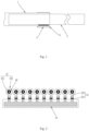
Fig. 1 is a schematic structural diagram of the insulated telescopic arm according to an embodiment of the present disclosure; -
Fig. 2 is a schematic structural diagram of the self-adjusting roller apparatus according to an embodiment of the present disclosure from a viewing angle; -
Fig. 3 is a schematic structural diagram of the self-adjusting roller apparatus according to an embodiment of the present disclosure from another viewing angle; -
Fig. 4 is a schematic structural diagram of the pressure cylinder according to an embodiment of the present disclosure; -
Fig. 5 is a schematic structural diagram of the roller assembly and the piston rod according to one embodiment of the present disclosure from a viewing angle; -
Fig. 6 is a schematic structural diagram of the roller assembly and the piston rod according to one embodiment of the present disclosure from another viewing angle; -
Fig. 7 is a schematic structural diagram of the insulated inner arm and the self-adjusting roller apparatus according to an embodiment of the present disclosure; -
Fig. 8 is a schematic sectional view of the insulated telescopic arm according to an embodiment of the present disclosure; and -
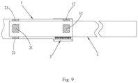
Fig. 9 is a schematic structural diagram of the insulated telescopic arm according to another embodiment of the present disclosure. - Some embodiments of the present disclosure will be detailed below with reference to the accompanying drawings. It may be understood that the embodiments described herein are only provided to describe and explain the present disclosure, but are not intended to constitute any limitation on the present disclosure.
- The insulated telescopic arm in the present disclosure will be described below with reference to the accompanying drawings.
- As shown in
Figs. 1 and 2 , the present disclosure provides an insulated telescopic arm, which includes: - an
outer arm 1; - an insulated
inner arm 2, which is confined in theouter arm 1 and can move and extend from a free end of theouter arm 1 in an axial direction; - a self-adjusting
roller apparatus 3, which includes apressure cylinder 31 arranged on theouter arm 1,piston rods 32 that can move up and down in thepressure cylinder 31, androller assemblies 33 for bearing the insulatedinner arm 2, at least tworoller assemblies 33 are provided, and eachroller assembly 33 includes aroller shaft 331 and aroller body 332 that is used for bearing the insulatedinner arm 2 and is rotatably sleeved outside theroller shaft 331, and two ends of theroller shaft 331 extending out of theroller body 332 are correspondingly connected to thepiston rods 32. - When the insulated telescopic arm is used, since the self-adjusting
roller apparatus 3 includes apressure cylinder 31 arranged on theouter arm 1,piston rods 32 that can move up and down in thepressure cylinder 31 androller assemblies 33 for bearing the insulatedinner arm 2, and at least tworoller assemblies 33 are provided, at least tworoller assemblies 33 can support the insulatedinner arm 2 respectively during the telescopic operation of the insulatedinner arm 2; in addition, theroller assembly 33 includes aroller shaft 331 and aroller body 332 that is used for bearing the insulatedinner arm 2 and is rotatably sleeved outside theroller shaft 331, and two ends of theroller shaft 331 extending out of theroller body 332 are correspondingly connected to thepiston rods 32, i.e., eachroller assembly 33 is correspondingly connected to twopiston rods 32 to support the two ends of theroller assembly 33 respectively. Thus, when the insulatedinner arm 2 extends from the free end of theouter arm 1 and is bent to a certain degree, thepiston rods 32 at the two ends of at least tworoller assemblies 33 can move up and down in thepressure cylinder 31 according to the bending condition of the insulatedinner arm 2, so as to realize automatic adjustment, and the at least tworoller assemblies 33 are in full contact with the insulatedinner arm 2 to ensure a rolling effect; in addition, owing to the fact that the fluid medium in thepressure cylinder 31 exerts equal pressure on eachpiston rod 32, the at least two roller assemblies 33 bear the pressure evenly, thereby the wear rate is greatly reduced, and the service life and insulated performance of the insulatedinner arm 2 are improved. Besides, the insulated telescopic arm provided by the present disclosure can also solve the technical problem of uneven pressure on the left and right ends of theroller assemblies 33. - Particularly, it may be noted that the number of the
roller assemblies 33 may be n (n is greater than or equal to 2); in that case, when thepiston rods 32 at the two ends of eachroller assembly 33 are placed in thepressure cylinder 31, a hydraulic system with 2npiston rods 32 can be formed. According to Pascal's law in engineering hydromechanics, after the specific pressure at any point in an incompressible static fluid is increased as a result of an external force, the increased specific pressure is instantaneously transferred to all points in the static fluid. That is to say, when certain specific pressure is applied on onepiston rod 32 in a hydraulic system, the same increased specific pressure will be generated on theother piston rods 32. Specifically, the law can be expressed by a formula P1 = P2 = ... = P2n, i.e., F1/S1 = F2/S2 = ... = F2n/S2n. Owing to the fact that the action areas of the2n piston rods 32 are the same, the force applied on eachpiston rod 32 is the same; thus, the at least tworoller assemblies 33 bear the pressure evenly, and the left and right ends of eachroller assembly 33 bear the pressure evenly. - In addition, the
outer arm 1 in the present disclosure may be a metal outer arm or an insulated outer arm, which may be selected according to the actual situation. Thepressure cylinder 31 in the present disclosure may be a hydraulic cylinder or a pneumatic cylinder; in the case of a hydraulic cylinder, the fluid medium in the hydraulic cylinder may include but is not limited to hydraulic oil; in the case of a pneumatic cylinder, the fluid medium in the pneumatic cylinder may include but is not limited to air. - As shown in
Figs. 2 and4 , in an embodiment of the present disclosure, thepressure cylinder 31 includes acylinder body 311 with acommunication space 313 formed therein and apiston lifting portion 312 with a liftingchannel 314 formed therein. Thecylinder body 311 is provided withpiston lifting portions 312 at positions corresponding to the two ends of theroller assembly 33, and thecommunication space 313 of thecylinder body 311 is in communication with the liftingchannels 314 of thepiston lifting portions 312. Since at least tworoller assemblies 33 are provided, thecylinder body 311 may be provided withpiston lifting portions 312 in quantity equal to two times of the quantity of theroller assemblies 33, in order to correspond to the two ends of eachroller assembly 33 in the at least tworoller assemblies 33, and the liftingchannel 314 of eachpiston lifting portion 312 is in communication with thecommunication space 313 of thecylinder body 311, so that the fluid medium in thecommunication space 313 can be injected into each liftingchannel 314 respectively. Besides, eachpiston rod 32 includes apiston body 321 arranged in the liftingchannel 314 and arod body 322 connecting thepiston body 321 and theroller shaft 331, thepiston body 321 is arranged in close fit with the peripheral wall of the liftingchannel 314, and therod body 322 is connected to the end of theroller shaft 331 extending out of theroller body 332. That is to say, thepiston body 321 can divide the liftingchannel 314 into two parts, specifically, one part of the liftingchannel 314 below thepiston body 321 is in communication with thecommunication space 313 and can be filled with the fluid medium, while the other part of the liftingchannel 314 above thepiston body 321 is blocked from communicating with thecommunication space 313 owing to the sealing effect of thepiston body 321, so that the fluid medium can't enter the part of the liftingchannel 314 above thepiston body 321. The arrangement of the liftingchannels 314 can ensure the stability of the up-and-down movement of thepiston rod 32, and thecommunication space 313 can communicate with the liftingchannels 314, so that eachpiston body 321 can bear the same acting force. - Specifically, in the case of n roller assemblies 33 (n is greater than or equal to 2), the number of the
piston lifting portions 312 of thepressure cylinder 31 is 2n, which is to say, the number of the liftingchannels 314 is 2n, the2n lifting channels 314 can be in communication with each other via thecommunication space 313 of thecylinder body 311, and the 2npiston lifting portions 312 are respectively arranged in one-to-one correspondence with the two ends of then roller assemblies 33. Thepiston bodies 321 with 2npiston rods 32 are arranged in 2n liftingchannels 314 in one-to-one correspondence, and are respectively connected to the ends of thecorresponding roller shafts 331 extending out of theroller body 332 via therod bodies 322. - As shown in
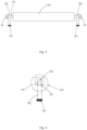
Figs. 2 ,3 and5 , in an embodiment of the present disclosure, thepiston rod 32 is provided with amovement hole 323, and the self-adjustingroller apparatus 3 further includes retaining nuts 34. The two ends of theroller shaft 331 extending out of theroller body 332 pass through the correspondingmovement hole 323 and the retainingnuts 34 sequentially, and are connected with the retainingnuts 34 through threads. That is to say, thepiston rod 32 may be provided with amovement hole 323 for theroller shaft 331 to pass there-through, an end of theroller shaft 331 passing through themovement hole 323 is provided with an external threaded section, and a retainingnut 34 is sleeved on the external threaded section to limit the axial movement of theroller shaft 331; moreover, the two ends of theroller shaft 331 of eachroller assembly 33 are correspondingly provided with apiston rod 32 and a retainingnut 34, so that the two ends of theroller assembly 33 can be connected to twopiston rods 32 respectively. Eachpiston rod 32 is detachably connected with theroller assembly 33 to facilitate maintenance and service. As shown inFig. 6 , in an embodiment of the present disclosure, themovement hole 323 is formed with amovement clearance 324 for theroller shaft 331 to move up and down. Thepiston rod 32 is connected to theroller shaft 331 through themovement hole 323, and the diameter of themovement hole 323 in the height direction is greater than the shaft diameter of theroller shaft 331, so that when theroller shaft 331 is inserted through themovement hole 323, amovement clearance 324 exists in themovement hole 323 for theroller shaft 331 to move up and down; thus, when the insulatedinner arm 2 extends out and bears an offset load, the two ends of theroller shaft 331 can be adjusted adaptively in thecorresponding movement hole 323, as shown inFig. 7 . - In an embodiment of the present disclosure, the
roller shaft 331 may have a circular cross section, and themovement hole 323 may be a square hole. In order to form amovement clearance 324 in themovement hole 323 for theroller shaft 331 to move up and down, the distance between the upper inner wall and the lower inner wall of themovement hole 323 configured as a square hole may be greater than the diameter of the circular cross section of theroller shaft 331. - In an embodiment of the present disclosure, a bearing element may be provided between the
roller shaft 331 and theroller body 332. Thus, theroller body 332 can roll with minimal friction. Specifically, two bearing elements are provided, and the two bearing elements are arranged at two ends on the inner side of theroller body 332, so that theroller body 332 can be supported from the two ends. - Please see
Fig. 1 again. In an embodiment of the present disclosure, a lower side plate of theouter arm 1 bulges downward to form a mountingspace 11 for accommodating thepressure cylinder 31, so as to minimize the size of theouter arm 1. Specifically, theouter arm 1 includes an upper side plate and a lower side plate that are oppositely arranged, and a left side plate and a right side plate that are oppositely arranged, and the mountingspace 11 may be arranged near the free end of theouter arm 1. - As shown in
Figs. 8 and9 , in an embodiment of the present disclosure, the insulated telescopic arm further includes afirst stop block 12, which is arranged on the inner wall of theouter arm 1 and used for abutting against the upper side and the left and right sides of the insulatedinner arm 2. That is to say, thefirst stop block 12 arranged on theouter arm 1 cooperates with the self-adjustingroller apparatus 3 to limit the insulatedinner arm 2 from the periphery of the insulatedinner arm 2, so that the insulatedinner arm 2 can be accurately centered during the telescopic operation. Specifically, three first stop blocks 12 may be provided, and the three first stop blocks 12 are respectively arranged on the inner walls of the upper side plate, the left side plate and the right side plate of theouter arm 1 corresponding to the self-adjustingroller apparatus 3. Of course, the present disclosure is not limited to that arrangement. Alternatively, thefirst stop block 12 may be designed into an integral structure, and may be arranged on the inner walls of the left side plate, the upper side plate and the right side plate of theouter arm 1 sequentially. - Furthermore, the
first stop block 12 may be mounted to theouter arm 1 by means of threaded fasteners, and thefirst stop block 12 may be made of nylon or rubber. - As shown in
Fig. 9 , in an embodiment of the present disclosure, the insulated telescopic arm further includes asecond stop block 21, which is arranged on the outer peripheral wall of the inner end of the insulatedinner arm 2 and used for abutting against the inner wall of theouter arm 1. That is to say, thesecond stop block 21 arranged on the insulatedinner arm 2 can limit the insulatedinner arm 2 from the periphery of the insulatedinner arm 2 at the inner end of the insulatedinner arm 2, so as to further ensure that the insulatedinner arm 2 can be accurately centered during the telescopic operation. Specifically, four second stop blocks 21 may be provided, and the four second stop blocks 21 may be respectively arranged on the outer peripheral wall of the insulatedinner arm 2 and respectively abut against the inner walls of the upper side plate, the lower side plate, the left side plate and the right side plate of theouter arm 1 in one-to-one correspondence. Of course, the present disclosure is not limited to that arrangement. Alternatively, thesecond stop block 21 may be designed into an integral structure, and may be arranged around the outer peripheral wall of the inner end of the insulatedinner arm 2. It may be noted particularly that the inner end of the insulatedinner arm 2 is referred in relation to the outer end of the insulatedinner arm 2. The outer end of the insulatedinner arm 2 refers to the end that can extend out of the free end of theouter arm 1, while the inner end of the insulatedinner arm 2 refers to the end that can't extend out of the free end of theouter arm 1. Furthermore, thesecond stop block 21 may be mounted to the insulatedinner arm 2 by means of threaded fasteners, and thesecond stop block 21 may be made of nylon or rubber. In addition, in a case that theouter arm 1 is an insulated outer arm, thesecond stop block 21 at the upper end of the outer arm may be replaced by the self-adjustingroller apparatus 3 to reduce the wear between the insulated outer arm and the inner end of the insulatedinner arm 2. - Please see
Figs. 1 and 2 again. In an embodiment of the present disclosure, a plurality ofroller assemblies 33 are provided, eachroller assembly 33 extends in the width direction of theouter arm 1, and the plurality ofroller assemblies 33 are sequentially arranged at an interval in the length direction of theouter arm 1. The number of theroller assemblies 33 may be more than two or even up to ten, and may be determined according to the actual requirement. Since the two ends of each of the plurality ofroller assemblies 33 can be connected with apiston rod 32 that can move up and down in thepressure cylinder 31, the plurality ofroller assemblies 33 bear the pressure evenly; in addition, as the number of theroller assemblies 33 is increased, the pressure evenly exerted on eachroller assembly 33 by the insulatedinner arm 2 can be decreased, so as to further attain the purpose of reducing wear. - In order to attain the above object, the present disclosure further provides an insulated bucket arm vehicle, which includes the insulated telescopic arm described above. Since the insulated bucket arm vehicle employs all the technical schemes in the above embodiments, it at least has all the beneficial effects brought by the technical schemes in the above embodiments, which will not be further detailed here.
- In the description herein, it may be understood that the terms "first" and "second" are used only for a descriptive purpose, but shall not be interpreted as indicating or implying relative importance or implicitly indicating the quantity of the indicated technical features. Hence, a feature defined by "first" or "second" may explicitly or implicitly include at least one such feature. In the description of the present disclosure, "a plurality" means at least two, such as two or more, etc., unless otherwise specified explicitly.
- In the present disclosure, unless otherwise specified and defined explicitly, the terms "install", "connect", "fix", etc. shall be interpreted in their general meanings. For example, a connection may be a fixed connection, a detachable connection, or an integral connection; may be a mechanical connection or an electrical connection or in communication with each other; may be a direct connection or an indirect connection via an intermediate medium, or internal communication or interactive relation between two elements. Those having ordinary skills in the art may interpret the specific meanings of the terms in the present disclosure in their context.
- In the description of the present disclosure, the expressions of reference terms "an embodiment", "some embodiments", "an example", "a specific example", or "some examples" mean that the specific features, structures, materials or characteristics described in those embodiments or examples are included in at least one embodiment or example of the present disclosure. In this specification, the exemplary expressions of the above terms may not necessarily refer to the same embodiment or example. Moreover, the specific features, structures, materials, or characteristics described can be combined appropriately in any one or more embodiments or examples. Furthermore, those skilled in the art may combine or assemble different embodiments or examples and features in different embodiments or examples described herein, provided that there is no conflict among them.
- While the present disclosure is illustrated and described above in embodiments, it may be understood that the embodiments are exemplary only and shall not be deemed as constituting any limitation on the present disclosure. Those skilled in the art can made variations, modifications, and replacements to the embodiments within the scope of the present disclosure.
Claims (10)
- An insulated telescopic arm, comprising:an outer arm (1);an insulated inner arm (2), which is confined in the outer arm (1) and can extend from a free end of the outer arm (1) in a length direction of the outer arm (1);a self-adjusting roller apparatus (3), comprising a pressure cylinder (31) arranged on the outer arm (1), piston rods (32) that are in sliding fit with the pressure cylinder (31) and can move up and down with respect to the pressure cylinder (31), and at least two roller assemblies (33) for bearing the insulated inner arm (2), wherein each of the roller assemblies (33) comprises a roller shaft (331) and a roller body (332) that is used for bearing the insulated inner arm (2) and is rotatably sleeved outside the roller shaft (331), and two ends of the roller shaft (331) extending out of the roller body (332) are correspondingly connected to the piston rods (32).
- The insulated telescopic arm of claim 1, wherein the pressure cylinder (31) comprises a cylinder body portion (311) with a communication space (313) formed therein and piston lifting portions (312) with lifting channels (314) formed therein, wherein the piston lifting portions (312) are arranged on the cylinder body portion (311) respectively at positions corresponding to the two ends of the roller assemblies (33), the communication space (313) is in communication with the lifting channels (312), and each piston rod (32) comprises a piston body (321) slidably fitted in the lifting channel (314) and a rod body (322) connecting the piston body (321) and the roller shaft (331).
- The insulated telescopic arm of claim 1, wherein each piston rod (32) is provided with a movement hole (323), and the self-adjusting roller apparatus (3) further comprises retaining nuts (34); the two ends of the roller shaft (331) extending out of the roller body (332) pass through corresponding movement holes (323) and the retaining nuts (34) respectively, and are connected with the retaining nuts (34) through threads.
- The insulated telescopic arm of claim 3, wherein the movement hole (323) has a movement clearance (324) formed therein for the roller shaft (331) to move up and down.
- The insulated telescopic arm of claim 4, wherein the roller shaft (331) has a circular cross section, and the movement hole (323) is a square hole.
- The insulated telescopic arm of any one of claims 1 to 5, wherein a lower side plate of the outer arm (1) bulges downward to form a mounting space (11) for accommodating the pressure cylinder (31).
- The insulated telescopic arm of any one of claims 1 to 5, further comprising a first stop block (12), which is arranged on an inner wall of the outer arm (1) and used for abutting against an upper side and left and right sides of the insulated inner arm (2).
- The insulated telescopic arm of any one of claims 1 to 5, further comprising a second stop block (21), which is arranged on an outer peripheral wall of an inner end of the insulated inner arm (2) and used for abutting against the inner wall of the outer arm (1).
- The insulated telescopic arm of any one of claims 1 to 5, wherein a plurality of roller assemblies (33) is provided, each roller assembly (33) extends in a width direction of the outer arm (1), and the plurality of roller assemblies (33) are sequentially arranged at an interval in the length direction of the outer arm (1).
- An insulated bucket arm vehicle, comprising the insulated telescopic arm of any one of claims 1 to 9.
Applications Claiming Priority (2)
| Application Number | Priority Date | Filing Date | Title |
|---|---|---|---|
| CN202211028096.3A CN117623194A (en) | 2022-08-25 | 2022-08-25 | Insulated telescopic arm and insulated bucket arm truck |
| PCT/CN2023/089457 WO2024041000A1 (en) | 2022-08-25 | 2023-04-20 | Insulated telescopic arm and insulated bucket arm vehicle |
Publications (2)
| Publication Number | Publication Date |
|---|---|
| EP4545475A1 true EP4545475A1 (en) | 2025-04-30 |
| EP4545475A4 EP4545475A4 (en) | 2025-10-01 |
Family
ID=90012297
Family Applications (1)
| Application Number | Title | Priority Date | Filing Date |
|---|---|---|---|
| EP23856095.7A Pending EP4545475A4 (en) | 2022-08-25 | 2023-04-20 | INSULATED TELESCOPIC ARM AND VEHICLE WITH INSULATED BUCKET ARM |
Country Status (4)
| Country | Link |
|---|---|
| US (1) | US20260103370A1 (en) |
| EP (1) | EP4545475A4 (en) |
| CN (1) | CN117623194A (en) |
| WO (1) | WO2024041000A1 (en) |
Family Cites Families (14)
| Publication number | Priority date | Publication date | Assignee | Title |
|---|---|---|---|---|
| FR2531691B1 (en) * | 1982-08-10 | 1986-03-28 | Ppm Sa | TELESCOPIC BOOM WITH DEVICES FOR SUPPORTING AND / OR GUIDING ITS IMPROVED SECTIONS |
| JP2003261291A (en) * | 2002-03-08 | 2003-09-16 | Aichi Corp | Polygon telescopic boom guide device |
| CN103174715A (en) * | 2011-12-23 | 2013-06-26 | 苏州海伦哲专用车辆有限公司 | Telescopic boom sliding block device |
| CN202429970U (en) * | 2011-12-30 | 2012-09-12 | 徐州海伦哲专用车辆股份有限公司 | Rolling roller device for insulating telescopic arm |
| CN103112785B (en) * | 2013-02-18 | 2013-12-11 | 愚公机械股份有限公司 | Retractable arm slide block assembly and retractable arm |
| CN103508336A (en) * | 2013-09-18 | 2014-01-15 | 国家电网公司 | Insulation arm for crane in electricity operation |
| CN203603970U (en) * | 2013-10-30 | 2014-05-21 | 湖南金能科技股份有限公司 | Telescopic boom for underground explosive loading truck |
| CN104847759B (en) * | 2014-09-15 | 2017-04-05 | 北汽福田汽车股份有限公司 | A kind of telescopic jib and the crane with which and creter crane |
| CN205151539U (en) * | 2015-10-21 | 2016-04-13 | 上海东普起重机械有限公司 | Hoisting machinery supporting leg wheelset |
| CN206328118U (en) * | 2016-12-14 | 2017-07-14 | 青岛吉特汽车科技有限公司 | One kind mixing arm type insulating overhead operating vehicle telescopic arm idler wheel mechanism |
| CN106829760A (en) * | 2017-03-30 | 2017-06-13 | 中国铁建重工集团有限公司 | A kind of telescopic arm |
| CN209823062U (en) * | 2019-06-18 | 2019-12-20 | 江苏通宇钢管集团有限公司 | Grounding device of circular cylinder barrel welding machine |
| EP3872022A1 (en) * | 2020-02-28 | 2021-09-01 | Hiab AB | A telescopic boom, and a crane and a vehicle provided with the telescopic boom |
| CN111960340A (en) * | 2020-08-14 | 2020-11-20 | 国网重庆市电力公司电力科学研究院 | Guide wheel mechanism, insulating bucket arm and insulating bucket arm vehicle |
-
2022
- 2022-08-25 CN CN202211028096.3A patent/CN117623194A/en active Pending
-
2023
- 2023-04-20 EP EP23856095.7A patent/EP4545475A4/en active Pending
- 2023-04-20 WO PCT/CN2023/089457 patent/WO2024041000A1/en not_active Ceased
- 2023-04-20 US US19/105,082 patent/US20260103370A1/en active Pending
Also Published As
| Publication number | Publication date |
|---|---|
| CN117623194A (en) | 2024-03-01 |
| EP4545475A4 (en) | 2025-10-01 |
| US20260103370A1 (en) | 2026-04-16 |
| WO2024041000A1 (en) | 2024-02-29 |
Similar Documents
| Publication | Publication Date | Title |
|---|---|---|
| US20260103370A1 (en) | Insulated telescopic arm and insulated bucket arm vehicle | |
| CN210164715U (en) | Roll bending cylinder of cold continuous rolling mill | |
| CN219562299U (en) | Long-span deep hole machine tool ball screw auxiliary supporting device | |
| CN104847759A (en) | Telescopic arm frame and engineering machinery comprising same | |
| CN102464278B (en) | Linear drive device and semiconductor processing device with linear drive device | |
| CN201266012Y (en) | Hydraulic catch wheel apparatus | |
| CN115852536A (en) | A guide textile rubber roller with stable supporting force | |
| CN113027854B (en) | Roller leveler | |
| CN119056906B (en) | Wedge type cold-rolled winding drum and coiling machine with same | |
| CN207278206U (en) | A kind of universal rolling proof-wear sucker rod centralising device | |
| CN111355339A (en) | An anti-rotation guide structure for an electric cylinder | |
| CN101905255A (en) | Intermediate roll of leveling machine | |
| CN103174715A (en) | Telescopic boom sliding block device | |
| CN113235175A (en) | Compression roller device for controlling oiling rate of precursor | |
| CN213117228U (en) | Automatic gap adjusting device for multiple wet brakes | |
| CN223164875U (en) | A wear-resistant, pressure-resistant and deformation-resistant rubber roller | |
| CN201843850U (en) | Hydraulic cylinder component | |
| CN220980003U (en) | Lifting point longitudinally moving oil cylinder | |
| CN101749938A (en) | Hydraulic blocking wheel | |
| CN223732836U (en) | Sand making machine | |
| CN220591498U (en) | Go up core box hoist mechanism and core machine | |
| CN223224048U (en) | Novel pressure-equalizing compression roller mechanism | |
| CN219035183U (en) | Hydraulic cylinder guide structure | |
| CN220204510U (en) | Damper with novel structure | |
| CN222573950U (en) | Elastic force adjustment mechanism and oxygen-free copper rod guide mechanism |
Legal Events
| Date | Code | Title | Description |
|---|---|---|---|
| STAA | Information on the status of an ep patent application or granted ep patent |
Free format text: STATUS: THE INTERNATIONAL PUBLICATION HAS BEEN MADE |
|
| PUAI | Public reference made under article 153(3) epc to a published international application that has entered the european phase |
Free format text: ORIGINAL CODE: 0009012 |
|
| STAA | Information on the status of an ep patent application or granted ep patent |
Free format text: STATUS: REQUEST FOR EXAMINATION WAS MADE |
|
| 17P | Request for examination filed |
Effective date: 20250127 |
|
| AK | Designated contracting states |
Kind code of ref document: A1 Designated state(s): AL AT BE BG CH CY CZ DE DK EE ES FI FR GB GR HR HU IE IS IT LI LT LU LV MC ME MK MT NL NO PL PT RO RS SE SI SK SM TR |
|
| A4 | Supplementary search report drawn up and despatched |
Effective date: 20250828 |
|
| RIC1 | Information provided on ipc code assigned before grant |
Ipc: B66F 13/00 20060101AFI20250822BHEP Ipc: F16B 7/10 20060101ALI20250822BHEP Ipc: B66C 23/687 20060101ALI20250822BHEP Ipc: E02F 3/30 20060101ALI20250822BHEP |
|
| DAV | Request for validation of the european patent (deleted) | ||
| DAX | Request for extension of the european patent (deleted) |