EP4545416A1 - Electrically driven propulsion unit of an aerial vehicle, and aerial vehicle comprising an electrically driven propulsion unit - Google Patents
Electrically driven propulsion unit of an aerial vehicle, and aerial vehicle comprising an electrically driven propulsion unit Download PDFInfo
- Publication number
- EP4545416A1 EP4545416A1 EP23205755.4A EP23205755A EP4545416A1 EP 4545416 A1 EP4545416 A1 EP 4545416A1 EP 23205755 A EP23205755 A EP 23205755A EP 4545416 A1 EP4545416 A1 EP 4545416A1
- Authority
- EP
- European Patent Office
- Prior art keywords
- attachment structure
- attaching
- electrically driven
- propulsion unit
- driven propulsion
- Prior art date
- Legal status (The legal status is an assumption and is not a legal conclusion. Google has not performed a legal analysis and makes no representation as to the accuracy of the status listed.)
- Pending
Links
Images


Classifications
-
- B—PERFORMING OPERATIONS; TRANSPORTING
- B64—AIRCRAFT; AVIATION; COSMONAUTICS
- B64D—EQUIPMENT FOR FITTING IN OR TO AIRCRAFT; FLIGHT SUITS; PARACHUTES; ARRANGEMENT OR MOUNTING OF POWER PLANTS OR PROPULSION TRANSMISSIONS IN AIRCRAFT
- B64D27/00—Arrangement or mounting of power plants in aircraft; Aircraft characterised by the type or position of power plants
- B64D27/02—Aircraft characterised by the type or position of power plants
- B64D27/30—Aircraft characterised by electric power plants
- B64D27/34—All-electric aircraft
-
- B—PERFORMING OPERATIONS; TRANSPORTING
- B64—AIRCRAFT; AVIATION; COSMONAUTICS
- B64D—EQUIPMENT FOR FITTING IN OR TO AIRCRAFT; FLIGHT SUITS; PARACHUTES; ARRANGEMENT OR MOUNTING OF POWER PLANTS OR PROPULSION TRANSMISSIONS IN AIRCRAFT
- B64D27/00—Arrangement or mounting of power plants in aircraft; Aircraft characterised by the type or position of power plants
- B64D27/02—Aircraft characterised by the type or position of power plants
- B64D27/30—Aircraft characterised by electric power plants
- B64D27/35—Arrangements for on-board electric energy production, distribution, recovery or storage
-
- B—PERFORMING OPERATIONS; TRANSPORTING
- B64—AIRCRAFT; AVIATION; COSMONAUTICS
- B64D—EQUIPMENT FOR FITTING IN OR TO AIRCRAFT; FLIGHT SUITS; PARACHUTES; ARRANGEMENT OR MOUNTING OF POWER PLANTS OR PROPULSION TRANSMISSIONS IN AIRCRAFT
- B64D31/00—Power plant control systems; Arrangement of power plant control systems in aircraft
- B64D31/16—Power plant control systems; Arrangement of power plant control systems in aircraft for electric power plants
-
- B—PERFORMING OPERATIONS; TRANSPORTING
- B64—AIRCRAFT; AVIATION; COSMONAUTICS
- B64C—AEROPLANES; HELICOPTERS
- B64C11/00—Propellers, e.g. of ducted type; Features common to propellers and rotors for rotorcraft
- B64C11/001—Shrouded propellers
-
- B—PERFORMING OPERATIONS; TRANSPORTING
- B64—AIRCRAFT; AVIATION; COSMONAUTICS
- B64C—AEROPLANES; HELICOPTERS
- B64C29/00—Aircraft capable of landing or taking-off vertically, e.g. vertical take-off and landing [VTOL] aircraft
- B64C29/0008—Aircraft capable of landing or taking-off vertically, e.g. vertical take-off and landing [VTOL] aircraft having its flight directional axis horizontal when grounded
- B64C29/0016—Aircraft capable of landing or taking-off vertically, e.g. vertical take-off and landing [VTOL] aircraft having its flight directional axis horizontal when grounded the lift during taking-off being created by free or ducted propellers or by blowers
- B64C29/0033—Aircraft capable of landing or taking-off vertically, e.g. vertical take-off and landing [VTOL] aircraft having its flight directional axis horizontal when grounded the lift during taking-off being created by free or ducted propellers or by blowers the propellers being tiltable relative to the fuselage
-
- F—MECHANICAL ENGINEERING; LIGHTING; HEATING; WEAPONS; BLASTING
- F16—ENGINEERING ELEMENTS AND UNITS; GENERAL MEASURES FOR PRODUCING AND MAINTAINING EFFECTIVE FUNCTIONING OF MACHINES OR INSTALLATIONS; THERMAL INSULATION IN GENERAL
- F16B—DEVICES FOR FASTENING OR SECURING CONSTRUCTIONAL ELEMENTS OR MACHINE PARTS TOGETHER, e.g. NAILS, BOLTS, CIRCLIPS, CLAMPS, CLIPS OR WEDGES; JOINTS OR JOINTING
- F16B2/00—Friction-grip releasable fastenings
- F16B2/02—Clamps, i.e. with gripping action effected by positive means other than the inherent resistance to deformation of the material of the fastening
- F16B2/06—Clamps, i.e. with gripping action effected by positive means other than the inherent resistance to deformation of the material of the fastening external, i.e. with contracting action
- F16B2/065—Clamps, i.e. with gripping action effected by positive means other than the inherent resistance to deformation of the material of the fastening external, i.e. with contracting action using screw-thread elements
Definitions
- the present invention relates to an electrically driven propulsion unit of an aerial vehicle and an aerial vehicle comprising the electrically driven propulsion unit.
- attachment structure needs to be rather thick, to accommodate the screw in a threaded hole. This in turn may impair the cooling efficiency of the electric and electronic components. It may also occur that the screw penetrates the attachment structure and affects a propulsion air flow provided at a radially outer side of the stator part.
- an electrically driven propulsion unit of an aerial vehicle which comprises: an attachment structure; and at least one attaching object to be attached to the attachment structure at a first side thereof, the at least one attaching object being an electric or electronic component.
- the present invention is characterized by further comprising at least one attaching device comprising an elastic element which attaches the attaching object by means of an elastic restoring force to the attachment structure.
- the attachment force can be provided by deformation of the elastic element. That is, there is no need for a complicate design such as providing a threaded hole in the attachment structure in order to establish the attachment force. Consequently, the attachment structure can be made thin and designed in view of other requirements such as cooling requirements. Furthermore, the attaching object can be easily replaced as only the elastic element needs to be deformed for replacement.
- the elastic restoring force is preferably caused by the geometries of the attachment structure, the elastic element, and the attaching object only.
- the elastic element can press the attaching object against the attachment structure due to its elastic deformation only. That means that the elastic restoring force does not require any particular action of a user such as fastening a screw.
- the electric component particularly refers to components used to supply and/or distribute and/or transform electric energy such as a battery, a cable and/or an electric motor.
- Electronic components additionally have a control function enabling the modification of electric energy such as a transistor or a relay.
- the attaching object is a power module in which various electric and/or electronic components are integrated.
- the power module is functionally interposed between the power source such as a battery and the consumer such as an electric motor.
- Power modules are characterized by interacting with other power modules to fulfil a certain specification.
- the elastic element/attaching device is installed to the attachment structure prior to attaching the attaching object. That is, the elastic element can be configured to provide the elastic restoring force in a state of being attached to the attachment structure.
- the elastic element is at least partially stretched to apply the restoring force.
- the elastic element in its natural state, can be at least partially shortened with respect to the deformed state. Thereby, the installation space can be maintained small.
- the elastic element may be bent to apply the elastic restoring force.
- the elastic element may substantially extend in a direction intersecting with the direction along which the elastic restoring force acts.
- an elastic restoring force may be applied to the attaching object at two different locations, preferably at two opposite end portions of the attaching object.
- the static support on the attachment structure can be increased, and, thus, the attachment can be performed more reliably.
- the respective elastic restoring force may be applied by the same elastic element or by different elastic elements.
- each attaching device can be made small.
- the at least one attaching device may be attached to the attachment structure at a location different from the location where the elastic restoring force is applied to the attaching object when seen along the direction of the elastic restoring force.
- the location of attachment of the attaching device may be shifted from the location of action of the elastic restoring force.
- the configuration can be made compact in the direction of the elastic restoring force.
- the attachment structure can be designed at the attachment location of the attaching device irrespective of the design required to support the attaching object. If the attachment structure has a substantially circular shape at the first side, an attachment location of the attaching device may be different in a circumferential direction of the attachment structure from the location where the elastic restoring force is applied to the attaching object.
- the configuration can be further simplified, the number of components may be reduced, and weight can be saved.
- a plurality of attaching objects may be provided along a circumferential direction of the attachment structure, preferably, to form a closed ring, preferably adjacent attaching objects along the circumferential direction share at least part of a common attaching device.
- the arrangement of the attaching objects can be made compact, while each attaching object can be efficiently cooled. It is to be noted that, at least on the first side, the attachment structure may extend along a circumferential direction.
- a smooth surface is a surface having substantially no irregularities.
- the smooth surface may also have a flat shape.
- the attachment structure may be a casing accommodating the at least one attaching object therein.
- the attaching object can be protected from the environment such as a propulsion air flow or free air flow.
- the casing need not be weakened by a hole in the region where the attaching object is attached, while the attaching object can still be reliably attached.
- the attachment structure preferably an engine control unit housing, may be arranged downstream of a propulsion rotating unit and/or propulsion static unit of the electrically driven propulsion unit.
- the propulsion rotating unit may be any unit which contributes in the generation of a propulsion air flow such as a fan or a compressor stage.
- the propulsion static unit may be any unit which interacts with the propulsion air flow such as static vanes.
- a propulsion air flow for generating a propulsion force may be configured to flow at a second side being opposite to the first side of the attachment structure, wherein, preferably, the attachment structure is exposed to a cooling air flow branched off from the propulsion air flow at the second side.
- heat can be transferred via the attachment structure from the first side where the attaching object is provided to the second side where the propulsion air flow can be used for forced convection.
- the elastic element may be in face contact with the attaching object.
- the elastic restoring force can be distributed, and damage to the attaching object can be prevented. Further, heat can be transferred via the elastic element.
- the attachment structure may have surface increasing portions, in particular fins and/or ribs, at a second side opposite to the first side.
- the cooling performance can be further increased as a greater surface for heat transfer can be provided.
- the elastic element preferably the entire at least one attaching device, may comprise a thermally conductive material, in particular, steel and/or titanium, may be preferably formed thereof.
- heat can be transferred via the elastic element itself.
- Steel and/or titanium can ensure mechanical stability such that the attachment can be made reliable.
- Another aspect provides an aerial vehicle comprising the electrically driven propulsion unit according to at least one of the preceding aspects, wherein the aerial vehicle is preferably of a VTOL type.
- the proposed attachment structure of the propulsion unit, engine, of the electric aerial vehicle is a part of the engine, more specifically an engine control unit housing to attach power modules.
- the engine control unit (ECU) housing is an approximately cylindrical item provided at the back of the engine.
- the outer surface of the housing forms the inner surface of the annular engine duct for the propulsion air flow.
- the propulsion air flow flows over the surface, hence it is used to cool the power electronics employed within the engine control unit.
- the power electronics used are in the form of power modules.
- the power modules are arranged in a circular pattern and are attached to the inner surface of the ECU housing, providing the shortest possible thermal path between the power module and the air used for cooling.
- the housing thickness is optimised to minimise the mass whilst fulfilling thermal (heat spreading) and structural requirements.
- the resulting thickness is too thin for attaching the power modules using the commonly used/state of the art screw solutions.
- This invention solves that problem by providing a means to attach power modules into the housing using spring-like fixations, that do not impose requirements on housing thickness as a normal screw would. That is, the thickness correlates in such a manner with the thermal resistance of the attachment structure, that the bigger the thickness the higher the thermal resistance is and vice versa. Also, the thickness correlates in a reverse manner with the rate of heat convection by the propulsion air flow such that the bigger the thickness, the smaller the heat convection rate is and vice versa.
- the attachment structure engine control unit housing
- conventionally may have a thickness of 4 mm to accommodate a screw head.
- the thickness may be reduced to less than 4 mm, preferably less than 2 mm, for example, 1 mm.
- the thermal resistance of the attachment structure can be reduced up to 75%, wherefore the entire thermal resistance between an electric or electronic component and the propulsion air flow, to which the resistance of the attachment structure contributes with about 20%, can be reduced up to 15%. This increases the convection amount and the efficiency.
- weight can be saved in two ways. On the one hand, by the smaller attachment structure itself weight can be saved. On the other hand, as the convection rate is increased, the fins and/or ribs can be reduced in size and mass to comply with a predetermined heat discharge rate such that the propulsion unit can be made compact.
- a longitudinal axis of the aircraft is designated as x-axis.
- a transversal axis, which extends along the wing span is designated as y-axis, and a vertical axis, which forms an orthogonal right hand system with the x- and y-axis is designated as z-axis.
- Fig. 1 shows an aircraft which is designated by reference numeral 1 in perspective view.
- the aircraft 1 comprises a wing 2.
- the aircraft 1 comprises a left wing 2a and a right wing 2b extending on both sides of the x-axis of a fuselage 3, respectively, along the y-axis of the aircraft 1.
- a plurality of propulsion units 4 are attached on both of the left and right wings 2a and 2b.
- the propulsion units 4 are attached to a rear portion, in particular a rear end portion such as a trailing edge, of the wings 2.
- the plurality of propulsion units 4 are aligned along the y-axis of the aircraft 1.
- the propulsion units 4 are arrayed along an arrangement direction which is aligned with the y-axis of the aircraft.
- the propulsion units 4 are attached to be pivotable about a pivot axis parallel to the y-axis.
- the propulsion units 4 are pivotable between a substantially horizontal orientation (cruise flight mode shown in Fig. 1 ) and a substantially vertical orientation (take-off or hover flight mode).
- a substantially horizontal orientation cruise flight mode shown in Fig. 1
- a substantially vertical orientation take-off or hover flight mode
- On the wings 2a and 2b an array of nine propulsion units 4 is provided, respectively.
- At least one actuator is provided for each propulsion unit 4 to set the orientation of the propulsion unit 4 with respect to the wing 2.
- the propulsion units 4 of the array of propulsion units 4 may form an integral unit, which is actuated by at least one actuator.
- the propulsion units of each array are preferably pivoted synchronously, that is, there orientation with respect to the wing 2 or canard 5 may be the same.
- the aircraft 1 comprises the canard 5.
- a left canard 5a and a right canard 5b are provided to both sides of the x-axis in front of the wings 2a and 2b.
- Propulsion units 6 are attached to a rear portion, in particular to a rear end portion such as a trailing edge of the canards 5.
- the propulsion units 6 are also attached to the canard 5 to be pivotable around an axis parallel to the y-axis.
- six propulsion units 6 are provided to form an array, respectively.
- the propulsion units 6 may be different in configuration, in particular, in terms of size, drive type, and maximum thrust, from the propulsion units 4. Thus, they have different reference signs.
- the present invention may be applied to both of propulsion units 4 and 6. They are electrically driven, preferably, by a rotary electric machine such as an electric motor.
- the aerial vehicle 1 is symmetrical with respect to the wings 2a and 2b, the canards 5a and 5b, as well as the arrangement of the propulsion units 4 and 6.
- propulsion unit 4 is of a ducted fan type. It is preferable if the propulsion units 4 and/or 6 form a flight control surface, respectively, in particular, a secondary flight control surface such as a flap.
- the fan 41 is encompassed by a cowling 43.
- the cowling 43 forms, at its radially inner side, a duct 44, together with a radially outer side of a stator part 7.
- the stator part 7 is located substantially at the center of the propulsion unit 4 (coaxially with the thrust axis) and rotatably supports the fan 41.
- the stator part 7 is connected to the cowling 43 by static vanes 7a which are provided in regular intervals circumferentially about the thrust axis and form a propulsion static unit.
- the cowling 43 may form the flight control surface at its outer side. That is, the cowling 43 can act such as to vary the lift generated by the wings 2 and/or the canards 5.
- the engine control unit housing 7b is provided downstream of the propulsion rotating unit 41 and the propulsion static unit 7a, but can be provided downstream of only one of them. It is further provided downstream of the electric motor. It can be formed integrally with the stator part 7, in particular, in a monolithic manner or as a separate component.
- the power modules 8 are arranged at intervals along the circumferential direction, in particular, in equally spaced intervals. They are arranged at the same location along the thrust axis. In other words, they align in the circumferential direction.
- Each power module 8 can comprise several electronic components such as transistors.
- the power modules forming an engine control unit (ECU) can control the operation of the aforementioned electric motor.
- Each power module 8 has a substantially parallelepiped shape, in particular a square shape.
- the stator part 7 has, along the circumferential direction, contact area portions 71 (six) which are equally spaced, and which may have the aforementioned thickness of 1 mm. It further has mounting portions 72 which are equally spaced and provided in the respective gaps between the contact area portions 71 along the circumferential direction.
- Each contact area portion 71 has a respective attaching object attached thereto. It has a flat contact surface at its radially inner side which is in face contact with a flat radially outer surface of the power module 8.
- the surface of the stator part 7 (engine control unit housing 7b) can be divided into six circumferential sectors, where the respective contact surface is a chord in the cross sectional view.
- a radially outer surface (at the second side B) of the contact area portion 71 has a circular arc shape and is provided with surface increasing portions 73.
- the surface increasing portions 73 have the shape of fins and extend parallel to the thrust axis, that is, to the propulsion air flow direction. They are spaced apart from each other along a direction perpendicular to the propulsion air flow direction (along substantially the circumferential direction)
- the mounting portion 72 has flat surfaces at both of the radially inner and outer side. It is to be noted that the mounting portion has a reinforced portion which has a greater thickness than at least the contact area portion 71.
- the electrically driven propulsion unit 4 further comprises an attaching device 9 at the first side A.
- the attaching device 9 has an elastic element 10. Furthermore, a screw 12 is provided for attaching the elastic element 10 to the stator part 7.
- the elastic element 10 is a bent part, and is symmetrical with respect to a center plane which is perpendicular to the circumferential direction and is a plane including the thrust axis and the radial direction.
- the elastic element may be bent from a sheet metal.
- the elastic element 10 includes a support part 11a, a folded part 11b, and a contact part 11c.
- the support part 11a extends substantially parallel to the attachment structure at a certain location, that is, perpendicular to the radial direction and parallel to the inner surface of the mounting portion 72. It has a threaded hole penetrating along the radial direction (perpendicular to the mounting portion 72). The screw 12 is screwed into the threaded hole.
- the folded part 11b is connected to the support part 11a (at both sides along the circumferential direction) and is folded such that it extends substantially perpendicular to the support part 11a and thus away from the attachment structure 7 (mounting portion 72). Then, in the folded part 11b, the elastic element 10 extends outward and towards the attachment structure. At an outward end portion, the contact part 11c is connected which extends further outward and away from the attachment structure 7 taken at the certain location. The contact part 11c is made such that it can establish face contact with the power modules 8.
- the attaching object can be reliably secured to the attachment structure at two opposite end portions.
- the attaching object can be easily replaced as no screw needs to be unfastened. This is in particular advantageous if the attaching object is the power module. Since power modules can be combined with each other in various ways, it is possible to adapt to various specifications by replacing a power module.
- the elastic element 10 As the elastic element 10 is bent, it is partially stretched at a side of the elastic element which is located against the bending direction from the neutral fiber. Further, the elastic element 10 extends at least partially with at least a component in a direction perpendicular to the direction of the elastic restoring force (perpendicular to the radial direction). Finally, the elastic element, in particular, the contact part 11c is deformed to be further away from the attachment structure. Any of these features ensures a compact configuration.
- the attaching device 9 is attached to the mounting portion 72 which is at a location different from the location where the elastic restoring force is applied and where the attaching object is attached to the attachment structure 7, when seen along the direction along which the elastic restoring force acts.
- the elastic restoring force acts along the radial direction.
- the mounting portion 72 is shifted from the contact area portion 71 and the contact part 11b.
- the mounting portion 72 is shifted from the contact area portion along the circumferential direction.
- Adjacent attaching objects 8 share the support part 11a of the elastic element 10. Thus, they share at least part of a common attaching device and a common elastic element. Thus, loads can be commonly inserted into the attachment structure, and the number of components can be reduced.
- the common elastic element is integrally, in particular, monolithicly formed.
- the attachment structure has a circumferential direction.
- the circumferential direction is not an exact circular direction.
- the circumferential direction extends parallel to each flat surface of the contact area portion 71 and the mounting portion 72.
- the various sectors approximate a circular direction.
- the radial direction means, in particular, the radial direction at each center of a sector.
- the attaching objects 8 are arranged along the circumferential direction.
- the configuration can be made compact, and cooling efficiency can be enhanced.
- the attachment structure 8 has respective flat surfaces (contact surfaces). Thus, stable contact can be provided. This applies even more if the attaching object is in face contact with the contact surface.
- the attaching object are attached to the attachment structure 7 at the location of the cross section III-III which is downstream of the propulsion rotating unit 41 along the propulsion air flow direction.
- the energized air flow can increase cooling efficiency, in particular, if the fins 73 are provided.
- the propulsion air flow flows at the radially outer side of the attachment structure (at the second side).
- the elastic element 10 has the contact part 11c which is in face contact with the attaching object.
- the contact load can be well distributed and the attaching object can be spared.
- the elastic element 10 is formed of a material having thermal conductivity, in particular, a thermal coefficient of at least 15 W/(m K), more preferably of at least 20 W/(m K).
- a material having thermal conductivity in particular, a thermal coefficient of at least 15 W/(m K), more preferably of at least 20 W/(m K).
- Such material may comprise titanium or steel, alone or in combination.
- FIG. 6a shows the attachment variant of the embodiment where the attaching device is fastened by the screw 12 from the second side which is favourable in terms of assembly
- Fig. 6b shows a modification.
- the screw 112 is threaded into a threaded hole in the mounting portion 172 of the attachment structure while the elastic element 110 has a through hole.
- the screw does not impair the propulsion air flow.
- Fig. 6c shows a further modification.
- the attaching device (elastic element 210) is not secured by a screw inserted along the direction perpendicular to the attachment structure (along the radial direction) but along a direction perpendicular thereto, in the present case, parallel to the thrust axis.
- the elastic element 210 has a tab 211d provided at the support part 211a and bent such that it overlaps with the mounting portion 272 along the direction parallel to the thrust axis.
- a through hole is provided in the tab 211 d, and a threaded hole is provided in the mounting portion 272 such that a screw can be inserted along the direction parallel to the thrust axis.
- the elastic element is bent, it may also be compressed.
- a compression spring may be provided as elastic element.
- a common elastic element is used for adjacent attaching objects, it is also possible to provide at least part of a common attaching device as a support part to which two separate elastic elements are provided at both sides.
- the attachment structure need not be the stator part 7 (casing).
- the attachment structure can also be a mounting plate. It is further not necessary that the attachment structure has a circumferential extension.
- the attaching object instead of or in addition to the flat surfaces, arc shaped surfaces can be provided. Then, it is preferable if also the attaching object has a corresponding arc shape surface at the side facing the attachment structure. It is also possible that, a ring shaped surface is formed at the first side.
- the propulsion air flow may be branched off such that a cooling air flow flows towards the radially inner side of the duct 44 and parallel to the thrust axis, and flows at the second side of the attachment structure.
- fins other surface increasing portions can be provided, for example, regular or irregular protrusions, ribs, and the like. It is preferable if the fins and/or ribs extend parallel to the thrust axis.
Landscapes
- Engineering & Computer Science (AREA)
- Aviation & Aerospace Engineering (AREA)
- Vibration Prevention Devices (AREA)
- Motor Or Generator Frames (AREA)
Abstract
Description
- The present invention relates to an electrically driven propulsion unit of an aerial vehicle and an aerial vehicle comprising the electrically driven propulsion unit.
- In the prior art, for example, in
US 2022 266 987 A1 , there is known an electrically driven propulsion unit in which several electric and electronic components are installed. In particular, a controller is integrated in a stator part of the electrically driven propulsion unit. In other words, the controller comprising the electric and electronic components is an attaching object, while the stator part is an attachment structure. - It has been devised to attach the attaching object to the attachment structure by means of screws which are screwed into the attachment structure.
- However, such attachment has certain shortcomings. That is, the attachment structure needs to be rather thick, to accommodate the screw in a threaded hole. This in turn may impair the cooling efficiency of the electric and electronic components. It may also occur that the screw penetrates the attachment structure and affects a propulsion air flow provided at a radially outer side of the stator part.
- It is therefore an object of the present invention to provide an electrically driven propulsion unit in which an electric and/or electronic component can be attached in a more efficient manner.
- This object is achieved by an electrically driven propulsion unit having the features of
claim 1. - According to a first aspect, an electrically driven propulsion unit of an aerial vehicle is provided which comprises: an attachment structure; and at least one attaching object to be attached to the attachment structure at a first side thereof, the at least one attaching object being an electric or electronic component.
- Particularly differing from the prior art, the present invention is characterized by further comprising at least one attaching device comprising an elastic element which attaches the attaching object by means of an elastic restoring force to the attachment structure.
- According thereto, the attachment force can be provided by deformation of the elastic element. That is, there is no need for a complicate design such as providing a threaded hole in the attachment structure in order to establish the attachment force. Consequently, the attachment structure can be made thin and designed in view of other requirements such as cooling requirements. Furthermore, the attaching object can be easily replaced as only the elastic element needs to be deformed for replacement.
- In this regard, it is to be noted that the elastic restoring force is preferably caused by the geometries of the attachment structure, the elastic element, and the attaching object only. The elastic element can press the attaching object against the attachment structure due to its elastic deformation only. That means that the elastic restoring force does not require any particular action of a user such as fastening a screw.
- In the present disclosure, the electric component particularly refers to components used to supply and/or distribute and/or transform electric energy such as a battery, a cable and/or an electric motor. Electronic components additionally have a control function enabling the modification of electric energy such as a transistor or a relay. Preferably, the attaching object is a power module in which various electric and/or electronic components are integrated. The power module is functionally interposed between the power source such as a battery and the consumer such as an electric motor. Power modules are characterized by interacting with other power modules to fulfil a certain specification.
- It is preferable that the elastic element/attaching device is installed to the attachment structure prior to attaching the attaching object. That is, the elastic element can be configured to provide the elastic restoring force in a state of being attached to the attachment structure.
- Preferably, the elastic element is at least partially stretched to apply the restoring force.
- Thus, in its natural state, the elastic element can be at least partially shortened with respect to the deformed state. Thereby, the installation space can be maintained small. In particular, the elastic element may be bent to apply the elastic restoring force.
- Alternatively or additionally, the elastic element may substantially extend in a direction intersecting with the direction along which the elastic restoring force acts.
- Thereby, the installation space can further be reduced.
- According to a further aspect, an elastic restoring force may be applied to the attaching object at two different locations, preferably at two opposite end portions of the attaching object.
- Thus, the static support on the attachment structure can be increased, and, thus, the attachment can be performed more reliably. In this regard, the respective elastic restoring force may be applied by the same elastic element or by different elastic elements.
- Preferably, at least two attaching devices are provided to apply the elastic restoring force to one attaching object, respectively.
- Hence, the attachment can be performed more reliably. In addition, each attaching device can be made small.
- According to still a further aspect, the at least one attaching device may be attached to the attachment structure at a location different from the location where the elastic restoring force is applied to the attaching object when seen along the direction of the elastic restoring force.
- According to this aspect, the location of attachment of the attaching device may be shifted from the location of action of the elastic restoring force. Thus, the configuration can be made compact in the direction of the elastic restoring force. Further, the attachment structure can be designed at the attachment location of the attaching device irrespective of the design required to support the attaching object. If the attachment structure has a substantially circular shape at the first side, an attachment location of the attaching device may be different in a circumferential direction of the attachment structure from the location where the elastic restoring force is applied to the attaching object.
- According to still a further aspect, at least two attaching objects may share at least part of a common attaching device.
- Thus, the configuration can be further simplified, the number of components may be reduced, and weight can be saved.
- According to still a further aspect, a plurality of attaching objects may be provided along a circumferential direction of the attachment structure, preferably, to form a closed ring, preferably adjacent attaching objects along the circumferential direction share at least part of a common attaching device.
- According thereto, the arrangement of the attaching objects can be made compact, while each attaching object can be efficiently cooled. It is to be noted that, at least on the first side, the attachment structure may extend along a circumferential direction.
- Alternatively or additionally, the attachment structure may have a smooth surface at the first side, in particular, in an arc or ring shape.
- Thus, stable contact between the attachment structure and the attaching object can be provided which fosters the cooling efficiency. A smooth surface is a surface having substantially no irregularities. The smooth surface may also have a flat shape.
- According to still a further aspect, the at least one attaching object may be in face contact with the attachment structure.
- Thereby, a relatively high amount of heat can be transferred to the attachment structured, and cooling of the attaching object can be improved.
- According to still a further aspect, the attachment structure may be a casing accommodating the at least one attaching object therein.
- Consequently, the attaching object can be protected from the environment such as a propulsion air flow or free air flow. In the context of the present invention, the casing need not be weakened by a hole in the region where the attaching object is attached, while the attaching object can still be reliably attached.
- According to still a further aspect, the attachment structure, preferably an engine control unit housing, may be arranged downstream of a propulsion rotating unit and/or propulsion static unit of the electrically driven propulsion unit.
- Thus, an energized propulsion air flow can be used for cooling. Further, weight balance can be increased. The propulsion rotating unit may be any unit which contributes in the generation of a propulsion air flow such as a fan or a compressor stage. The propulsion static unit may be any unit which interacts with the propulsion air flow such as static vanes.
- According to still a further aspect, a propulsion air flow for generating a propulsion force may be configured to flow at a second side being opposite to the first side of the attachment structure, wherein, preferably, the attachment structure is exposed to a cooling air flow branched off from the propulsion air flow at the second side.
- Hence, heat can be transferred via the attachment structure from the first side where the attaching object is provided to the second side where the propulsion air flow can be used for forced convection.
- According to still a further aspect, the elastic element may be in face contact with the attaching object.
- Thus, the elastic restoring force can be distributed, and damage to the attaching object can be prevented. Further, heat can be transferred via the elastic element.
- According to still a further aspect, the attachment structure may have surface increasing portions, in particular fins and/or ribs, at a second side opposite to the first side.
- Thus, the cooling performance can be further increased as a greater surface for heat transfer can be provided.
- According to still a further aspect, the elastic element, preferably the entire at least one attaching device, may comprise a thermally conductive material, in particular, steel and/or titanium, may be preferably formed thereof.
- Hence, heat can be transferred via the elastic element itself. Steel and/or titanium can ensure mechanical stability such that the attachment can be made reliable.
- Another aspect provides an aerial vehicle comprising the electrically driven propulsion unit according to at least one of the preceding aspects, wherein the aerial vehicle is preferably of a VTOL type.
- In such an aerial vehicle, the above mentioned effects can be achieved. In a VTOL aerial vehicle, considerable propulsion forces may occur such that high cooling rates are required. Further, when switching between different orientations of the propulsion unit, high mechanical loads may occur for which the above aspects are preferable.
- In other words, the proposed attachment structure of the propulsion unit, engine, of the electric aerial vehicle is a part of the engine, more specifically an engine control unit housing to attach power modules. The engine control unit (ECU) housing is an approximately cylindrical item provided at the back of the engine. The outer surface of the housing forms the inner surface of the annular engine duct for the propulsion air flow. The propulsion air flow flows over the surface, hence it is used to cool the power electronics employed within the engine control unit. The power electronics used are in the form of power modules. The power modules are arranged in a circular pattern and are attached to the inner surface of the ECU housing, providing the shortest possible thermal path between the power module and the air used for cooling. The housing thickness is optimised to minimise the mass whilst fulfilling thermal (heat spreading) and structural requirements. The resulting thickness is too thin for attaching the power modules using the commonly used/state of the art screw solutions. This invention solves that problem by providing a means to attach power modules into the housing using spring-like fixations, that do not impose requirements on housing thickness as a normal screw would. That is, the thickness correlates in such a manner with the thermal resistance of the attachment structure, that the bigger the thickness the higher the thermal resistance is and vice versa. Also, the thickness correlates in a reverse manner with the rate of heat convection by the propulsion air flow such that the bigger the thickness, the smaller the heat convection rate is and vice versa. For example, the attachment structure (engine control unit housing) conventionally may have a thickness of 4 mm to accommodate a screw head. By means of the present invention, the thickness may be reduced to less than 4 mm, preferably less than 2 mm, for example, 1 mm. In this case, the thermal resistance of the attachment structure can be reduced up to 75%, wherefore the entire thermal resistance between an electric or electronic component and the propulsion air flow, to which the resistance of the attachment structure contributes with about 20%, can be reduced up to 15%. This increases the convection amount and the efficiency.
- Furthermore, weight can be saved in two ways. On the one hand, by the smaller attachment structure itself weight can be saved. On the other hand, as the convection rate is increased, the fins and/or ribs can be reduced in size and mass to comply with a predetermined heat discharge rate such that the propulsion unit can be made compact.
- The present invention will be now described in detail by making reference to the accompanying drawings.
-
Fig. 1 shows an aerial vehicle to which the electrically driven propulsion unit of the present invention is applied. -
Fig. 2 shows a longitudinal sectional view of a propulsion unit. -
Fig. 3 shows a cross section of the propulsion unit. -
Fig. 4 shows a perspective view of the attachment region shown inFig. 3 -
Fig. 5 shows a perspective view of an attaching device. -
Fig. 6 shows alternatives for attaching the attaching device to the attachment structure. - In the drawings, a longitudinal axis of the aircraft is designated as x-axis. A transversal axis, which extends along the wing span is designated as y-axis, and a vertical axis, which forms an orthogonal right hand system with the x- and y-axis is designated as z-axis.
-
Fig. 1 shows an aircraft which is designated byreference numeral 1 in perspective view. Theaircraft 1 comprises awing 2. In particular, theaircraft 1 comprises aleft wing 2a and aright wing 2b extending on both sides of the x-axis of afuselage 3, respectively, along the y-axis of theaircraft 1. - On both of the left and
right wings propulsion units 4 are attached. Thepropulsion units 4 are attached to a rear portion, in particular a rear end portion such as a trailing edge, of thewings 2. The plurality ofpropulsion units 4 are aligned along the y-axis of theaircraft 1. In particular, thepropulsion units 4 are arrayed along an arrangement direction which is aligned with the y-axis of the aircraft. - The
propulsion units 4 are attached to be pivotable about a pivot axis parallel to the y-axis. In particular, thepropulsion units 4 are pivotable between a substantially horizontal orientation (cruise flight mode shown inFig. 1 ) and a substantially vertical orientation (take-off or hover flight mode). On thewings propulsion units 4 is provided, respectively. - At least one actuator is provided for each
propulsion unit 4 to set the orientation of thepropulsion unit 4 with respect to thewing 2. It is to be noted that at least some of thepropulsion units 4 of the array ofpropulsion units 4 may form an integral unit, which is actuated by at least one actuator. However, it is preferable that some, preferably all,propulsion units 4 may be pivoted individually and independently from the others. The propulsion units of each array are preferably pivoted synchronously, that is, there orientation with respect to thewing 2 orcanard 5 may be the same. - In addition, the
aircraft 1 comprises thecanard 5. In particular, a left canard 5a and a right canard 5b are provided to both sides of the x-axis in front of thewings Propulsion units 6 are attached to a rear portion, in particular to a rear end portion such as a trailing edge of thecanards 5. Thepropulsion units 6 are also attached to thecanard 5 to be pivotable around an axis parallel to the y-axis. On the canards 5a and 5b, sixpropulsion units 6 are provided to form an array, respectively. - The
propulsion units 6 may be different in configuration, in particular, in terms of size, drive type, and maximum thrust, from thepropulsion units 4. Thus, they have different reference signs. The present invention may be applied to both ofpropulsion units - The
aircraft 1 is of a vertical-take-off-and-landing type. Thepropulsion units 4 and/or 6 may thus be configured to pivot in an angle range of at least 90°, preferably 110°. - It is to be noted that the
aerial vehicle 1 is symmetrical with respect to thewings propulsion units - Reference is made to
Figs. 2 to 5 , which show an exemplary electrically drivenpropulsion unit 4. However, the present invention may also apply topropulsion unit 6 attached to thecanard 5. As can be taken therefrom,propulsion unit 4 is of a ducted fan type. It is preferable if thepropulsion units 4 and/or 6 form a flight control surface, respectively, in particular, a secondary flight control surface such as a flap. - In particular, the
propulsion unit 4 includes a propulsion rotating unit 41 (fan). Thepropulsion rotating unit 41 can generate a propulsion force (thrust force) by rotation about therotation axis 42 driven by the electric motor. The rotation of thefan 41 sucks air along to form a propulsion air flow along a direction which is substantially parallel to therotation axis 42. Therotation axis 42 is also a thrust axis which is preferably spaced apart from an attachment portion of thepropulsion unit 4 at the wing. That is, the thrust axis preferably has a lever arm with respect to the pivot axis. In the orientation shown inFigs. 1 and 2 , the thrust axis is aligned with the x-axis, that is, thepropulsion unit 4 is in horizontal orientation. It is to be noted that in hover flight, the thrust axis may be aligned with the z-axis. By means of pivoting thepropulsion unit 4, thrust vectoring is enabled. - The
fan 41 is encompassed by acowling 43. Thecowling 43 forms, at its radially inner side, aduct 44, together with a radially outer side of astator part 7. Thestator part 7 is located substantially at the center of the propulsion unit 4 (coaxially with the thrust axis) and rotatably supports thefan 41. Thestator part 7 is connected to thecowling 43 bystatic vanes 7a which are provided in regular intervals circumferentially about the thrust axis and form a propulsion static unit. It is to be noted that thecowling 43 may form the flight control surface at its outer side. That is, thecowling 43 can act such as to vary the lift generated by thewings 2 and/or thecanards 5. -
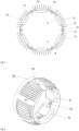
Fig. 3 is a cross section taken at line III-III inFig. 2 . It shows that thestator part 7 is formed in an overall ring shape, that is, has a completely revolving wall part along a circumferential direction. Thestator part 7 accommodates at its radially inner side A (a first side) several electronic components such aspower modules 8. Thestator part 7 forms an attachment structure according to the invention in form of a casing (enginecontrol unit housing 7b which is shown inFigs. 2 to 4 ) for thepower modules 8 which are attaching objects, respectively. That is, thepower modules 8 form an ECU (engine control unit) housed in the enginecontrol unit housing 7b. It is to be noted that the enginecontrol unit housing 7b is provided downstream of thepropulsion rotating unit 41 and the propulsionstatic unit 7a, but can be provided downstream of only one of them. It is further provided downstream of the electric motor. It can be formed integrally with thestator part 7, in particular, in a monolithic manner or as a separate component. Thepower modules 8 are arranged at intervals along the circumferential direction, in particular, in equally spaced intervals. They are arranged at the same location along the thrust axis. In other words, they align in the circumferential direction. - Each
power module 8 can comprise several electronic components such as transistors. The power modules forming an engine control unit (ECU) can control the operation of the aforementioned electric motor. - Each
power module 8 has a substantially parallelepiped shape, in particular a square shape. - The
stator part 7 has, along the circumferential direction, contact area portions 71 (six) which are equally spaced, and which may have the aforementioned thickness of 1 mm. It further has mountingportions 72 which are equally spaced and provided in the respective gaps between thecontact area portions 71 along the circumferential direction. Eachcontact area portion 71 has a respective attaching object attached thereto. It has a flat contact surface at its radially inner side which is in face contact with a flat radially outer surface of thepower module 8. As there are provided sixpower modules 8, at the radially inner side, the surface of the stator part 7 (enginecontrol unit housing 7b) can be divided into six circumferential sectors, where the respective contact surface is a chord in the cross sectional view. A radially outer surface (at the second side B) of thecontact area portion 71 has a circular arc shape and is provided withsurface increasing portions 73. Thesurface increasing portions 73 have the shape of fins and extend parallel to the thrust axis, that is, to the propulsion air flow direction. They are spaced apart from each other along a direction perpendicular to the propulsion air flow direction (along substantially the circumferential direction) - The mounting
portion 72 has flat surfaces at both of the radially inner and outer side. It is to be noted that the mounting portion has a reinforced portion which has a greater thickness than at least thecontact area portion 71. - The electrically driven
propulsion unit 4 further comprises an attachingdevice 9 at the first side A. The attachingdevice 9 has anelastic element 10. Furthermore, ascrew 12 is provided for attaching theelastic element 10 to thestator part 7. - The
elastic element 10 is a bent part, and is symmetrical with respect to a center plane which is perpendicular to the circumferential direction and is a plane including the thrust axis and the radial direction. The elastic element may be bent from a sheet metal. - The
elastic element 10 includes asupport part 11a, a foldedpart 11b, and acontact part 11c. - The
support part 11a extends substantially parallel to the attachment structure at a certain location, that is, perpendicular to the radial direction and parallel to the inner surface of the mountingportion 72. It has a threaded hole penetrating along the radial direction (perpendicular to the mounting portion 72). Thescrew 12 is screwed into the threaded hole. - The folded
part 11b is connected to thesupport part 11a (at both sides along the circumferential direction) and is folded such that it extends substantially perpendicular to thesupport part 11a and thus away from the attachment structure 7 (mounting portion 72). Then, in the foldedpart 11b, theelastic element 10 extends outward and towards the attachment structure. At an outward end portion, thecontact part 11c is connected which extends further outward and away from theattachment structure 7 taken at the certain location. Thecontact part 11c is made such that it can establish face contact with thepower modules 8. - The attaching
device 9, that is, theelastic element 10 is attached to the mountingportion 72. Thescrew 12 is screwed into the threaded hole from the radially outer side (second side) of theattachment structure 7. A through hole is provided in the reinforced portion to have the screw inserted thereto. It is preferable if thescrew 12 is accommodated in the attachment structure, for example, via a countersunk hole. - Each symmetric half (contact part) of the
elastic element 10 is contacting adifferent power module 8 at a respective end portion of therespective power module 8. Onepower module 8 in turn is contacted at respective end portions thereof in the circumferential direction by two different elastic elements, respectively. - Function and effect of the present invention are now described.
- As can be taken from
Fig. 3 , in particular, thepower modules 8 have clampedportions 8a which protrude from respective end portions along the circumferential direction at the radially outer end. The clampedportions 8a have a reduced thickness compared to the rest of thepower module 8. - With respective two adjacent attaching
devices 9 attached to the respective mountingportions 72, the power module can be inserted along the propulsion air flow direction (parallel to the thrust axis) between therespective contact parts 11c and the attachment structure, in particular, thecontact area portion 71. To this end, thecontact part 11c can be bent slightly in a direction away from the attachment structure. Upon return to its natural state, thecontact part 11c gets in contact with the clampedportion 8a, such that a residual elastic bending deformation remains in the elastic element. - Consequently, the attaching object is arranged between the
elastic element 10 and the attachment structure along a radial direction. The elastic deformation causes an elastic restoring force acting upon the attaching object pressing the attaching object against the attachment structure. The elastic restoring force acts substantially along the radial direction which is perpendicular to the contact surface of the attachment structure. - Thus, the attaching object can be reliably secured to the attachment structure at two opposite end portions.
- Further, there is no need to provide a hole in the
contact area portion 71. Thus, said portion can be made rather thin which enhances cooling efficiency. - Further, the attaching object can be easily replaced as no screw needs to be unfastened. This is in particular advantageous if the attaching object is the power module. Since power modules can be combined with each other in various ways, it is possible to adapt to various specifications by replacing a power module.
- As the
elastic element 10 is bent, it is partially stretched at a side of the elastic element which is located against the bending direction from the neutral fiber. Further, theelastic element 10 extends at least partially with at least a component in a direction perpendicular to the direction of the elastic restoring force (perpendicular to the radial direction). Finally, the elastic element, in particular, thecontact part 11c is deformed to be further away from the attachment structure. Any of these features ensures a compact configuration. - The attaching
device 9 is attached to the mountingportion 72 which is at a location different from the location where the elastic restoring force is applied and where the attaching object is attached to theattachment structure 7, when seen along the direction along which the elastic restoring force acts. As best seen inFig. 3 , the elastic restoring force acts along the radial direction. When seen in this direction, the mountingportion 72 is shifted from thecontact area portion 71 and thecontact part 11b. In particular, the mountingportion 72 is shifted from the contact area portion along the circumferential direction. Thus, bending can be ensured, and the configuration can be made compact. - Adjacent attaching
objects 8 share thesupport part 11a of theelastic element 10. Thus, they share at least part of a common attaching device and a common elastic element. Thus, loads can be commonly inserted into the attachment structure, and the number of components can be reduced. In this case, the common elastic element is integrally, in particular, monolithicly formed. - The attachment structure has a circumferential direction. In this regard, it is pointed out that the circumferential direction is not an exact circular direction. For example, at the first side, the circumferential direction extends parallel to each flat surface of the
contact area portion 71 and the mountingportion 72. However, the various sectors approximate a circular direction. The radial direction means, in particular, the radial direction at each center of a sector. - The attaching
objects 8 are arranged along the circumferential direction. Thus, the configuration can be made compact, and cooling efficiency can be enhanced. - Further, the
attachment structure 8 has respective flat surfaces (contact surfaces). Thus, stable contact can be provided. This applies even more if the attaching object is in face contact with the contact surface. - The attaching object are attached to the
attachment structure 7 at the location of the cross section III-III which is downstream of thepropulsion rotating unit 41 along the propulsion air flow direction. Thus, the energized air flow can increase cooling efficiency, in particular, if thefins 73 are provided. The propulsion air flow flows at the radially outer side of the attachment structure (at the second side). - The
elastic element 10 has thecontact part 11c which is in face contact with the attaching object. Thus, the contact load can be well distributed and the attaching object can be spared. - Further, the
elastic element 10 is formed of a material having thermal conductivity, in particular, a thermal coefficient of at least 15 W/(m K), more preferably of at least 20 W/(m K). Such material may comprise titanium or steel, alone or in combination. - Thus, it can be ensured that heat is carried to the attachment structure via the attaching
device 9. - Modifications of the embodiment are now described.
- While
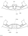
Fig. 6a ) shows the attachment variant of the embodiment where the attaching device is fastened by thescrew 12 from the second side which is favourable in terms of assembly,Fig. 6b ) shows a modification. Therein, thescrew 112 is threaded into a threaded hole in the mountingportion 172 of the attachment structure while theelastic element 110 has a through hole. Thus, the screw does not impair the propulsion air flow. -
Fig. 6c ) shows a further modification. Therein, the attaching device (elastic element 210) is not secured by a screw inserted along the direction perpendicular to the attachment structure (along the radial direction) but along a direction perpendicular thereto, in the present case, parallel to the thrust axis. Thereto theelastic element 210 has atab 211d provided at thesupport part 211a and bent such that it overlaps with the mountingportion 272 along the direction parallel to the thrust axis. A through hole is provided in thetab 211 d, and a threaded hole is provided in the mountingportion 272 such that a screw can be inserted along the direction parallel to the thrust axis. - Further, while in the embodiment, the elastic element is bent, it may also be compressed. For example, a compression spring may be provided as elastic element.
- While a common elastic element is used for adjacent attaching objects, it is also possible to provide at least part of a common attaching device as a support part to which two separate elastic elements are provided at both sides.
- Further, it is also possible that different attaching devices are used for each attaching object.
- The attachment structure need not be the stator part 7 (casing). The attachment structure can also be a mounting plate. It is further not necessary that the attachment structure has a circumferential extension.
- At the first side, instead of or in addition to the flat surfaces, arc shaped surfaces can be provided. Then, it is preferable if also the attaching object has a corresponding arc shape surface at the side facing the attachment structure. It is also possible that, a ring shaped surface is formed at the first side.
- Even not shown, the propulsion air flow may be branched off such that a cooling air flow flows towards the radially inner side of the
duct 44 and parallel to the thrust axis, and flows at the second side of the attachment structure. - Instead of fins, other surface increasing portions can be provided, for example, regular or irregular protrusions, ribs, and the like. It is preferable if the fins and/or ribs extend parallel to the thrust axis.
Claims (15)
- An electrically driven propulsion unit (4, 6) of an aerial vehicle (1), comprising:an attachment structure (7); andat least one attaching object (8) to be attached to the attachment structure (7) at a first side (A) thereof, the at least one attaching object (8) being an electric or electronic component, characterized by further comprisingat least one attaching device (9) comprising an elastic element (10) which attaches the attaching object (8) by means of an elastic restoring force to the attachment structure (7).
- The electrically driven propulsion unit (4, 6) according to claim 1, wherein the elastic element (10) is at least partially stretched to apply the elastic restoring force.
- The electrically driven propulsion unit (4, 6) according to claim 1 or 2, wherein an elastic restoring force is applied to the attaching object (8) at two different locations, preferably at two opposite end portions of the attaching object (8).
- The electrically driven propulsion unit (4, 6) according to claim 3, wherein at least two attaching devices (9) are provided to apply the elastic restoring force to one attaching object (8), respectively.
- The electrically driven propulsion unit (4, 6) according to at least one of the preceding claims, wherein the at least one attaching device (9) is attached to the attachment structure (7) at a location different from the location where the elastic restoring force is applied to the attaching object (8) when seen along the direction of the elastic restoring force, in particular, at a location different in a circumferential direction of the attachment structure from the location where the elastic restoring force is applied to the attaching object.
- The electrically driven propulsion unit (4, 6) according to at least one of the preceding claims, wherein at least two attaching objects (8) share at least part of a common attaching device (9).
- The electrically driven propulsion unit (4, 6) according to at least one of the preceding claims, wherein a plurality of attaching objects (8) are provided along a circumferential direction of the attachment structure (7), preferably, to form a closed ring, preferably adjacent attaching objects (8) along the circumferential direction share at least part of a common attaching device (9), and/or
the attachment structure (7) has a smooth surface at the first side (A), in particular, in a flat, arc, or ring shape. - The electrically driven propulsion unit (4, 6) according to at least one of the preceding claims, wherein the at least one attaching object (8) is in face contact with the attachment structure (7).
- The electrically driven propulsion unit (4, 6) according to at least one of the preceding claims, wherein the attachment structure (7) is a casing accommodating the at least one attaching object (8) therein.
- The electrically driven propulsion unit (4, 6) according to at least one of the preceding claims, wherein the the attachment structure (7), preferably an engine control unit housing (7b), is arranged downstream of a propulsion rotating unit (41) and/or propulsion static unit of the electrically driven propulsion unit (4, 6).
- The electrically driven propulsion unit (4, 6) according to at least one of the preceding claims, wherein a propulsion air flow for generating a propulsion force is configured to flow at a second side (B) being opposite to the first side (A) of the attachment structure (7), wherein, preferably, the attachment structure (7) is exposed to a cooling air flow branched off from the propulsion air flow at the second side (B).
- The electrically driven propulsion unit (4, 6) according to at least one of the preceding claims, wherein the elastic element (10) is in face contact with the attaching object (8).
- The electrically driven propulsion unit (4, 6) according to at least one of the preceding claims, wherein the attachment structure (7) has surface increasing portions, in particular fins (73) and/or ribs, at a second side (B) opposite to the first side (A).
- The electrically driven propulsion unit (4, 6) according to at least one of the preceding claims, wherein the elastic element (10), preferably the entire at least one attaching device (9), comprises a thermally conductive material steel and/or titanium, is preferably formed thereof.
- An aerial vehicle (1) comprising the electrically driven propulsion unit (4, 6) according to at least one of the preceding claims, wherein the aerial vehicle is preferably of a VTOL type.
Priority Applications (2)
| Application Number | Priority Date | Filing Date | Title |
|---|---|---|---|
| EP23205755.4A EP4545416A1 (en) | 2023-10-25 | 2023-10-25 | Electrically driven propulsion unit of an aerial vehicle, and aerial vehicle comprising an electrically driven propulsion unit |
| PCT/EP2024/080195 WO2025088098A1 (en) | 2023-10-25 | 2024-10-25 | Electrically driven propulsion unit of an aerial vehicle, and aerial vehicle comprising an electrically driven propulsion unit |
Applications Claiming Priority (1)
| Application Number | Priority Date | Filing Date | Title |
|---|---|---|---|
| EP23205755.4A EP4545416A1 (en) | 2023-10-25 | 2023-10-25 | Electrically driven propulsion unit of an aerial vehicle, and aerial vehicle comprising an electrically driven propulsion unit |
Publications (1)
| Publication Number | Publication Date |
|---|---|
| EP4545416A1 true EP4545416A1 (en) | 2025-04-30 |
Family
ID=88511180
Family Applications (1)
| Application Number | Title | Priority Date | Filing Date |
|---|---|---|---|
| EP23205755.4A Pending EP4545416A1 (en) | 2023-10-25 | 2023-10-25 | Electrically driven propulsion unit of an aerial vehicle, and aerial vehicle comprising an electrically driven propulsion unit |
Country Status (2)
| Country | Link |
|---|---|
| EP (1) | EP4545416A1 (en) |
| WO (1) | WO2025088098A1 (en) |
Citations (6)
| Publication number | Priority date | Publication date | Assignee | Title |
|---|---|---|---|---|
| US20090168358A1 (en) * | 2007-12-26 | 2009-07-02 | Keihin Corporation | Power drive unit |
| US20090168360A1 (en) * | 2008-01-02 | 2009-07-02 | Harman International Industries, Incorporated | Clamp for electrical devices |
| US20180376613A1 (en) * | 2017-06-23 | 2018-12-27 | Yazaki Corporation | Fixing structure of electronic component |
| GB2591104A (en) * | 2020-01-15 | 2021-07-21 | Rolls Royce Plc | Component for mounting arrangement, mounting arrangement and gas turbine engine comprising mounting arrangement |
| EP4037163A1 (en) * | 2021-01-28 | 2022-08-03 | Rolls-Royce plc | Electrical machine and power electronics converter |
| US20220266987A1 (en) | 2021-02-19 | 2022-08-25 | Lilium Eaircraft Gmbh | Integrated flap control unit |
-
2023
- 2023-10-25 EP EP23205755.4A patent/EP4545416A1/en active Pending
-
2024
- 2024-10-25 WO PCT/EP2024/080195 patent/WO2025088098A1/en active Pending
Patent Citations (6)
| Publication number | Priority date | Publication date | Assignee | Title |
|---|---|---|---|---|
| US20090168358A1 (en) * | 2007-12-26 | 2009-07-02 | Keihin Corporation | Power drive unit |
| US20090168360A1 (en) * | 2008-01-02 | 2009-07-02 | Harman International Industries, Incorporated | Clamp for electrical devices |
| US20180376613A1 (en) * | 2017-06-23 | 2018-12-27 | Yazaki Corporation | Fixing structure of electronic component |
| GB2591104A (en) * | 2020-01-15 | 2021-07-21 | Rolls Royce Plc | Component for mounting arrangement, mounting arrangement and gas turbine engine comprising mounting arrangement |
| EP4037163A1 (en) * | 2021-01-28 | 2022-08-03 | Rolls-Royce plc | Electrical machine and power electronics converter |
| US20220266987A1 (en) | 2021-02-19 | 2022-08-25 | Lilium Eaircraft Gmbh | Integrated flap control unit |
Also Published As
| Publication number | Publication date |
|---|---|
| WO2025088098A1 (en) | 2025-05-01 |
Similar Documents
| Publication | Publication Date | Title |
|---|---|---|
| EP2680289B1 (en) | Contactor mounting panel with improved thermal characteristics | |
| JP6265609B2 (en) | Aircraft engine mounting system | |
| US6351383B1 (en) | Heat conducting device for a circuit board | |
| US20110017426A1 (en) | Aircraft cooling system | |
| EP2688801B1 (en) | Aircraft tail region with a cooling system installed in said aircraft tail region | |
| WO2019016510A1 (en) | Aircraft control system | |
| US6735086B1 (en) | Heat-conducting device for circuit board | |
| WO2025088098A1 (en) | Electrically driven propulsion unit of an aerial vehicle, and aerial vehicle comprising an electrically driven propulsion unit | |
| JP5514621B2 (en) | Aircraft actuator hydraulic system | |
| EP3643606B1 (en) | Aircraft assembly with a hot-air exhaust outlet | |
| EP4105128A1 (en) | Heat dissipating light assembly | |
| EP2420652B1 (en) | Manifold mounting arrangement | |
| EP2772432B1 (en) | Rotary wing aircraft pitch beam attachment with anti-rotation plate design | |
| CN212259664U (en) | Heat dissipation device, heat dissipation assembly and mobile platform | |
| US6822870B2 (en) | Retaining apparatus | |
| CN111377049A (en) | Portable foldable unmanned aerial vehicle and working method thereof | |
| CN109693800A (en) | External flight device lamp unit | |
| US20250388330A1 (en) | Power unit of an unmanned aerial vehicle | |
| JP4564483B2 (en) | Planar active phased array antenna device | |
| CN208007304U (en) | The fixed structure and aircraft of aircraft electrical tune | |
| US12509237B2 (en) | Forward engine mount for a half or full wraparound pylon | |
| EP4140892B1 (en) | Heated pendulum damper | |
| CN113548198A (en) | A satellite configuration suitable for different satellite carrier installations | |
| JP6462884B2 (en) | Sensor array packaging solution | |
| US20250073931A1 (en) | Cooling structure for servomotor and robot |
Legal Events
| Date | Code | Title | Description |
|---|---|---|---|
| PUAI | Public reference made under article 153(3) epc to a published international application that has entered the european phase |
Free format text: ORIGINAL CODE: 0009012 |
|
| STAA | Information on the status of an ep patent application or granted ep patent |
Free format text: STATUS: REQUEST FOR EXAMINATION WAS MADE |
|
| STAA | Information on the status of an ep patent application or granted ep patent |
Free format text: STATUS: EXAMINATION IS IN PROGRESS |
|
| 17P | Request for examination filed |
Effective date: 20240410 |
|
| AK | Designated contracting states |
Kind code of ref document: A1 Designated state(s): AL AT BE BG CH CY CZ DE DK EE ES FI FR GB GR HR HU IE IS IT LI LT LU LV MC ME MK MT NL NO PL PT RO RS SE SI SK SM TR |
|
| 17Q | First examination report despatched |
Effective date: 20250402 |
|
| 19U | Interruption of proceedings before grant |
Effective date: 20250313 |
|
| 19W | Proceedings resumed before grant after interruption of proceedings |
Effective date: 20260401 |
|
| R17C | First examination report despatched (corrected) |
Effective date: 20260417 |
|
| 17Q | First examination report despatched |
Effective date: 20260430 |
|
| RAP1 | Party data changed (applicant data changed or rights of an application transferred) |
Owner name: ARCHER AVIATION INC. |