EP4545388A1 - STRAT-SEAT VEHICLE - Google Patents
STRAT-SEAT VEHICLE Download PDFInfo
- Publication number
- EP4545388A1 EP4545388A1 EP24206978.9A EP24206978A EP4545388A1 EP 4545388 A1 EP4545388 A1 EP 4545388A1 EP 24206978 A EP24206978 A EP 24206978A EP 4545388 A1 EP4545388 A1 EP 4545388A1
- Authority
- EP
- European Patent Office
- Prior art keywords
- frame
- bridge
- gas tank
- vehicle body
- straddle
- Prior art date
- Legal status (The legal status is an assumption and is not a legal conclusion. Google has not performed a legal analysis and makes no representation as to the accuracy of the status listed.)
- Pending
Links
Images



Classifications
-
- B—PERFORMING OPERATIONS; TRANSPORTING
- B62—LAND VEHICLES FOR TRAVELLING OTHERWISE THAN ON RAILS
- B62J—CYCLE SADDLES OR SEATS; AUXILIARY DEVICES OR ACCESSORIES SPECIALLY ADAPTED TO CYCLES AND NOT OTHERWISE PROVIDED FOR, e.g. ARTICLE CARRIERS OR CYCLE PROTECTORS
- B62J35/00—Fuel tanks specially adapted for motorcycles or engine-assisted cycles; Arrangements thereof
-
- B—PERFORMING OPERATIONS; TRANSPORTING
- B60—VEHICLES IN GENERAL
- B60K—ARRANGEMENT OR MOUNTING OF PROPULSION UNITS OR OF TRANSMISSIONS IN VEHICLES; ARRANGEMENT OR MOUNTING OF PLURAL DIVERSE PRIME-MOVERS IN VEHICLES; AUXILIARY DRIVES FOR VEHICLES; INSTRUMENTATION OR DASHBOARDS FOR VEHICLES; ARRANGEMENTS IN CONNECTION WITH COOLING, AIR INTAKE, GAS EXHAUST OR FUEL SUPPLY OF PROPULSION UNITS IN VEHICLES
- B60K15/00—Arrangement in connection with fuel supply of combustion engines or other fuel consuming energy converters, e.g. fuel cells; Mounting or construction of fuel tanks
- B60K15/03—Fuel tanks
- B60K15/063—Arrangement of tanks
-
- B—PERFORMING OPERATIONS; TRANSPORTING
- B60—VEHICLES IN GENERAL
- B60K—ARRANGEMENT OR MOUNTING OF PROPULSION UNITS OR OF TRANSMISSIONS IN VEHICLES; ARRANGEMENT OR MOUNTING OF PLURAL DIVERSE PRIME-MOVERS IN VEHICLES; AUXILIARY DRIVES FOR VEHICLES; INSTRUMENTATION OR DASHBOARDS FOR VEHICLES; ARRANGEMENTS IN CONNECTION WITH COOLING, AIR INTAKE, GAS EXHAUST OR FUEL SUPPLY OF PROPULSION UNITS IN VEHICLES
- B60K15/00—Arrangement in connection with fuel supply of combustion engines or other fuel consuming energy converters, e.g. fuel cells; Mounting or construction of fuel tanks
- B60K15/03—Fuel tanks
- B60K15/063—Arrangement of tanks
- B60K15/067—Mounting of tanks
- B60K15/07—Mounting of tanks of gas tanks
-
- B—PERFORMING OPERATIONS; TRANSPORTING
- B60—VEHICLES IN GENERAL
- B60K—ARRANGEMENT OR MOUNTING OF PROPULSION UNITS OR OF TRANSMISSIONS IN VEHICLES; ARRANGEMENT OR MOUNTING OF PLURAL DIVERSE PRIME-MOVERS IN VEHICLES; AUXILIARY DRIVES FOR VEHICLES; INSTRUMENTATION OR DASHBOARDS FOR VEHICLES; ARRANGEMENTS IN CONNECTION WITH COOLING, AIR INTAKE, GAS EXHAUST OR FUEL SUPPLY OF PROPULSION UNITS IN VEHICLES
- B60K15/00—Arrangement in connection with fuel supply of combustion engines or other fuel consuming energy converters, e.g. fuel cells; Mounting or construction of fuel tanks
- B60K15/03—Fuel tanks
- B60K15/073—Tank construction specially adapted to the vehicle
-
- B—PERFORMING OPERATIONS; TRANSPORTING
- B62—LAND VEHICLES FOR TRAVELLING OTHERWISE THAN ON RAILS
- B62K—CYCLES; CYCLE FRAMES; CYCLE STEERING DEVICES; RIDER-OPERATED TERMINAL CONTROLS SPECIALLY ADAPTED FOR CYCLES; CYCLE AXLE SUSPENSIONS; CYCLE SIDECARS, FORECARS, OR THE LIKE
- B62K11/00—Motorcycles, engine-assisted cycles or motor scooters with one or two wheels
- B62K11/02—Frames
- B62K11/04—Frames characterised by the engine being between front and rear wheels
-
- B—PERFORMING OPERATIONS; TRANSPORTING
- B62—LAND VEHICLES FOR TRAVELLING OTHERWISE THAN ON RAILS
- B62K—CYCLES; CYCLE FRAMES; CYCLE STEERING DEVICES; RIDER-OPERATED TERMINAL CONTROLS SPECIALLY ADAPTED FOR CYCLES; CYCLE AXLE SUSPENSIONS; CYCLE SIDECARS, FORECARS, OR THE LIKE
- B62K19/00—Cycle frames
- B62K19/30—Frame parts shaped to receive other cycle parts or accessories
-
- B—PERFORMING OPERATIONS; TRANSPORTING
- B60—VEHICLES IN GENERAL
- B60K—ARRANGEMENT OR MOUNTING OF PROPULSION UNITS OR OF TRANSMISSIONS IN VEHICLES; ARRANGEMENT OR MOUNTING OF PLURAL DIVERSE PRIME-MOVERS IN VEHICLES; AUXILIARY DRIVES FOR VEHICLES; INSTRUMENTATION OR DASHBOARDS FOR VEHICLES; ARRANGEMENTS IN CONNECTION WITH COOLING, AIR INTAKE, GAS EXHAUST OR FUEL SUPPLY OF PROPULSION UNITS IN VEHICLES
- B60K15/00—Arrangement in connection with fuel supply of combustion engines or other fuel consuming energy converters, e.g. fuel cells; Mounting or construction of fuel tanks
- B60K15/03—Fuel tanks
- B60K15/063—Arrangement of tanks
- B60K2015/0636—Arrangement of tanks the fuel tank being part of the chassis or frame
-
- B—PERFORMING OPERATIONS; TRANSPORTING
- B60—VEHICLES IN GENERAL
- B60K—ARRANGEMENT OR MOUNTING OF PROPULSION UNITS OR OF TRANSMISSIONS IN VEHICLES; ARRANGEMENT OR MOUNTING OF PLURAL DIVERSE PRIME-MOVERS IN VEHICLES; AUXILIARY DRIVES FOR VEHICLES; INSTRUMENTATION OR DASHBOARDS FOR VEHICLES; ARRANGEMENTS IN CONNECTION WITH COOLING, AIR INTAKE, GAS EXHAUST OR FUEL SUPPLY OF PROPULSION UNITS IN VEHICLES
- B60K15/00—Arrangement in connection with fuel supply of combustion engines or other fuel consuming energy converters, e.g. fuel cells; Mounting or construction of fuel tanks
- B60K15/03—Fuel tanks
- B60K15/063—Arrangement of tanks
- B60K2015/0637—Arrangement of tanks the fuel tank is arranged in the front of the vehicle
-
- B—PERFORMING OPERATIONS; TRANSPORTING
- B60—VEHICLES IN GENERAL
- B60Y—INDEXING SCHEME RELATING TO ASPECTS CROSS-CUTTING VEHICLE TECHNOLOGY
- B60Y2306/00—Other features of vehicle sub-units
- B60Y2306/01—Reducing damages in case of crash, e.g. by improving battery protection
Definitions
- the present invention relates to a straddle-type vehicle.
- a fuel cell vehicle that travels using electric power generated by a fuel cell has been developed.
- a hydrogen gas in a hydrogen tank and oxygen in air are chemically reacted in a fuel cell to generate electric power, and the generated electric power is supplied to a motor to drive wheels.
- a straddle-type vehicle provided with a gas fuel engine is developed, in which a hydrogen gas is used as gas fuel and combusted and the vehicle travels using combustion energy (for example, see Patent Literature 1).
- a gas tank is provided below the floor board in front of the engine.
- Patent Literature 1 JPH04-283128A
- a protective member may be provided in order to protect the gas tank from other components when receiving an impact from the rear side.
- various components are provided at the rear side of the gas tank, and in order to protect the gas tank from these components, the shape of the protective member may become complicated and the size of the vehicle may tend to be increased.
- the present invention has been made in view of the above, and an object of the present invention is to provide a straddle-type vehicle capable of appropriately protecting a gas tank from a component at the rear side of the tank.
- a straddle-type vehicle for traveling using gas fuel
- the straddle-type vehicle including: a vehicle body frame that forms a frame of a vehicle body; and a gas tank inside the vehicle body frame, in which the vehicle body frame includes a pair of frame portions that are located on both sides of the gas tank, and a bridge portion that connects the pair of frame portions at a rear side of the gas tank, and in which a fixing position of one end portion of the bridge portion and one frame portion is lower than a fixing position of the other end portion of the bridge portion and the other frame portion.
- the bridge portion obliquely crosses the rear side of the gas tank such that one end portion of the bridge portion is lower than the other end portion. Even if a plurality of components are arranged at the rear side of the gas tank in the left-right direction or the upper-lower direction, the bridge portion is positioned between the plurality of components and the gas tank. When the components move forward due to an impact or the like from the rear side, the gas tank is protected from the components by the bridge portion. Accordingly, the gas tank and the components are brought close to each other, and the gas tank and the components are compactly provided to reduce the size of the straddle-type vehicle.
- a straddle-type vehicle travels using gas fuel.
- the frame of the vehicle body of the straddle-type vehicle is formed by a vehicle body frame, and a gas tank is provided inside the vehicle body frame.
- a pair of frame portions are located on the lateral side of the gas tank, and a bridge portion that connects the pair of frame portions is located at the rear side of the gas tank.
- the fixing position of one end portion of the bridge portion and one frame portion is lower than the fixing position of the other end portion of the bridge portion and the other frame portion, and the bridge portion obliquely crosses the rear side of the gas tank.
- the bridge portion is positioned between the plurality of components and the gas tank.
- the components move forward due to an impact or the like from the rear side, the gas tank is protected from the components by the bridge portion. Accordingly, the gas tank and the components are brought close to each other, and the gas tank and the components are compactly provided to reduce the size of the straddle-type vehicle.
- FIG. 1 is a left side view of a vehicle internal structure according to the present embodiment.
- FIG. 2 is a right side view of the vehicle internal structure according to the present embodiment.
- an arrow Fr indicates the vehicle front side
- an arrow Re indicates the vehicle rear side
- an arrow L indicates the vehicle left side
- an arrow R indicates the vehicle right side.
- a straddle-type vehicle 1 is implemented by mounting various covers (not shown), as vehicle body exteriors, on a vehicle body frame 10 forming the frame of the vehicle body.
- a head pipe 11 is provided at the front end portion of the vehicle body frame 10, and a support frame 12 extends obliquely rearward and downward from the upper portion of the head pipe 11.
- a pair of first down frames 13 branch to the left and right from the lower portion of the support frame 12 and extend downward, and a pair of second down frames 14 branch to the left and right from the lower portion of the head pipe 11 and extend downward.
- a pair of main frames 15 are connected to the lower portions of the pair of first down frames 13 and the pair of second down frames 14.
- the pair of main frames 15 extend toward the vehicle rear side, and the intermediate portions of the pair of main frames 15 are connected to each other by an upper bridge 16.
- a pair of left-right asymmetric side frames 17 extend downward from the front ends of the pair of main frames 15.
- the side frames 17 are bent rearward at the lower portion of the vehicle, and then extend obliquely rearward and upward toward the rear portions of the pair of main frames 15.
- the front half portion of the vehicle body frame 10 is formed in a cradle shape by the pair of main frames 15 and the pair of side frames 17.
- a pair of foot boards 18 are attached to the pair of side frames 17.
- a pair of seat frames 19 extend rearward from the rear portions of the pair of main frames 15.
- the facing interval of the pair of seat frames 19 increases toward the middle of the frames, and then decreases toward the rear ends of the frames.
- the pair of seat frames 19 are formed in an arch shape, and the rear end portions of the pair of seat frames 19 are connected to each other.
- the front portions of the pair of seat frames 19 are connected to each other by an upper bridge 21.
- a rear portion of the pair of side frames 17 is connected to the upper bridge 21, and the upper bridge 21 is supported from the lower side by the pair of side frames 17.
- a front fork 33 is steerably supported on the head pipe 11, and a front wheel 34 is rotatably supported on the lower portion of the front fork 33.
- a long gas tank 60 is provided inside the cradle portion in the front half portion of the vehicle body frame 10. Gas fuel such as hydrogen is stored in the gas tank 60, and a tank valve 62 at the rear portion of the tank controls inflow and outflow of the gas fuel. The gas fuel is supplied from the tank valve 62 toward an injector (not shown) above a unit swing engine (an engine) 41 via fuel system components such as a plurality of pipes, a regulator 64, and a fuel hose 66.
- the unit swing engine 41 is swingably supported on support plates 31 of the left sub frame 28 and the right sub frame 29.
- the unit swing engine 41 is operated by the combustion energy of the gas fuel supplied from the gas tank 60.
- the cylinder axis of the unit swing engine 41 is inclined forward to be close to horizontal, and a cylinder assembly 43 extends forward of the vehicle from a crankcase 42.
- the cylinder assembly 43 enters between the left sub frame 28 and the right sub frame 29, and the front end of the cylinder assembly 43 is close to the tank valve 62 of the gas tank 60.
- An intake system component such as an air cleaner 51 is connected to the upper portion of the cylinder assembly 43, and an exhaust system component such as an exhaust pipe 56 or a muffler 58 is connected to the lower portion of the cylinder assembly 43.
- a CVT cover 47 is attached to the left side of the crankcase 42.
- a rear wheel 35 is rotatably supported on the rear portion of the CVT cover 47.
- a belt-type continuously variable transmission (not shown) is accommodated inside the CVT cover 47, and the driving force of the unit swing engine 41 is transmitted to the rear wheel 35 via a belt.
- the unit swing engine 41 is swung together with the muffler 58, the CVT cover 47, and the rear wheel 35.
- the straddle-type vehicle 1 is provided with a protective member that protects the gas tank 60 from other components when receiving an impact from the rear side.
- a protective member that protects the gas tank 60 from other components when receiving an impact from the rear side.
- On the rear side of the gas tank 60 not only a cylinder head cover 46 of the unit swing engine 41 but also a link mechanism 37 for the suspension 36 is provided. Since the link mechanism 37 is located below the cylinder head cover 46, the gas tank 60 cannot be appropriately protected by the protective member that extends only in the left-right direction. Therefore, in the present embodiment, a protection bridge (a bridge portion) 81 serving as a protective member is inclined diagonally in the left-right direction, thereby effectively protecting the gas tank 60 from a plurality of components that are arranged in the upper-lower direction.
- FIG. 3 is a left side view of a vehicle body central portion according to the present embodiment.
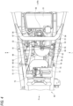
- FIG. 4 is a top view of the vehicle body central portion according to the present embodiment.
- the cylinder assembly 43 of the unit swing engine 41 is formed by stacking a cylinder 44, a cylinder head 45, and a cylinder head cover 46.
- An intake device is provided above the cylinder head 45.
- the intake device includes the air cleaner 51, a U-shaped outlet tube 52, a throttle body 53, and an intake pipe 54. Air is sent from the air cleaner 51 to the throttle body 53 through the outlet tube 52, and the intake amount is adjusted by the throttle body 53, then the air is supplied to the intake port of the cylinder head 45 through the intake pipe 54.
- An exhaust port is formed in the lower portion of the cylinder head 45, and the exhaust pipe 56 serving as an exhaust device is connected to the exhaust port.
- the exhaust pipe 56 is curved rearward from the lower surface of the cylinder head 45 and then extends to the vehicle rear side through the right side of the crankcase 42.
- the muffler 58 (see FIG. 2 ) inclined obliquely rearward and upward at the right side of the rear wheel 35 is connected to the rear end portion of the exhaust pipe 56.
- the exhaust gas flows into the exhaust pipe 56 from the exhaust port of the unit swing engine 41, flows rearward through the exhaust pipe 56, and then is discharged to the outside from the muffler 58.
- the tank valve 62 is provided at the rear end portion of the tank main body 61, and the regulator 64 is connected to a relief valve pipe 63 extending obliquely rearward and upward from the lower portion of the tank valve 62.
- the valve of the regulator 64 is opened to adjust the pressure of the gas fuel.
- a fuel filling port 77 is formed above the gas tank 60, and the upper portion of the tank valve 62 is connected to a filling pipe 78 that extends obliquely downward and rearward from the fuel filling port 77.
- the tank is filled with the gas fuel from the fuel filling port 77 through the tank valve 62.
- a radiator 30 for engine cooling is provided in front of the gas tank 60.
- a pair of frame portions of the vehicle body frame 10 are located on both sides of the gas tank 60, and the pair of frame portions are formed left-right asymmetrically by a pair of side frames 17L and 17R and a pair of lower frames 22L and 22R.
- the rear side portion of the left side frame 17L rises behind the rear side portion of the right side frame 17R, and the right lower frame 22R is formed longer than the left lower frame 22L in the front-rear direction (see FIGS. 1 and 2 ).
- the protection bridge 81 that obliquely crosses the rear side of the gas tank 60 is connected to the pair of frame portions.
- an L-shaped fixing plate 82 is provided at the right end portion of the protection bridge 81, and a vertical fixing plate 83 is provided at the left end portion of the protection bridge 81.
- the fixing plate 82 on the right end side of the protection bridge 81 is fixed to the right lower frame 22R, and the fixing plate 82 on the left end side of the protection bridge 81 is fixed to the rising rear side portion of the left side frame 17L.
- the fixing position of the right end portion of the protection bridge 81 and the right lower frame 22R is lower than the fixing position of the left end portion of the protection bridge 81 and the left side frame 17L.
- the protection bridge 81 extends obliquely, so that interference between the protection bridge 81 and the regulator 64 (see FIG. 3 ) is prevented.
- the protection bridge 81 is located between the gas tank 60 and the link mechanism 37, and the link mechanism 37 partially overlaps the intermediate position of the protection bridge 81 when viewed from the rear.
- the link mechanism 37 is provided close to the protection bridge 81 in the front-rear direction, and the gas tank 60 and the link mechanism 37 are compactly provided.
- the rear surface of the intermediate position of the protection bridge 81 is recessed, and a recess 84 is formed along the extending direction of the protection bridge 81.
- the recess 84 of the protection bridge 81 is positioned in front of the link mechanism 37. Accordingly, even if the link lever 38 of the link mechanism 37 swings, the interference between the protection bridge 81 and the link lever 38 is prevented.
- the cylinder head cover 46 (see FIG. 6 ) is also located at the rear side of the protection bridge 81, and the protection bridge 81 overlaps the link mechanism 37 and the cylinder head cover 46 when viewed from the rear. Therefore, even when the link mechanism 37 and the cylinder head cover 46 move forward due to an impact or the like from the rear side, the link mechanism 37 and the cylinder head cover 46 are received by the protection bridge 81, and the gas tank 60 is protected. Accordingly, the gas tank 60, the link mechanism 37, and the unit swing engine 41 can be compactly provided in the vehicle body frame 10, thereby reducing the size of the straddle-type vehicle 1.
- a triangular frame 20 is formed on the right (one) frame portion of the vehicle body frame 10 by a lower side portion that extends in the front-rear direction, a front oblique side portion that extends obliquely upward and rearward from the front end of the lower side portion, and a rear oblique side portion that extends obliquely upward and forward from the rear end of the lower side portion.
- the lower side portion of the triangular frame 20 is formed by the right lower frame 22R
- the front oblique side portion of the triangular frame 20 is formed by the right side frame 17R
- the rear oblique side portion of the triangular frame 20 is formed by the right side bridge 25.
- the fixing plate 82 on the right end side of the protection bridge 81 is fixed to the lower frame 22R serving as the lower side portion of the triangular frame 20.
- the triangular frame 20 has high rigidity, and the triangular frame 20 is less likely to be deformed even when receiving an impact or the like from the rear side.
- the protection bridge 81 is fixed to the triangular frame 20, so that displacement of the fixing position on the right end side of the protection bridge 81 is prevented.
- the protection bridge 81 is fixed to the lower frame 22R that has high rigidity in the front-rear direction. Accordingly, even if an impact or the like is received from the rear side, the displacement of the fixing position on the right end side of the protection bridge 81 is effectively prevented. Therefore, the gas tank 60 is protected from the rear components such as the link mechanism 37 and the cylinder head cover 46 by the protection bridge 81.
- the side frame 17L and the left sub frame 28 are connected to the left (the other) frame portion of the vehicle body frame 10 by a side bridge 26, and the side frame 17L and the main frame 15 are connected to each other by a side bridge 27.
- the side bridges 26 and 27 the rigidity of the side frame 17L is increased, and the side frame 17L is less likely to be deformed.
- the protection bridge 81 is fixed to the side frame 17L, so that the displacement of the fixing position on the left end side of the protection bridge 81 is prevented even when an impact from the rear side is received, and the gas tank 60 is protected from various rear components by the protection bridge 81.
- the protection bridge 81 obliquely crosses the rear side of the gas tank 60 such that the right end portion of the protection bridge 81 is lower than the left end portion. Even if the link mechanism 37 and the cylinder head cover 46 are arranged at the rear side of the gas tank 60 in the upper-lower direction, the protection bridge 81 is positioned between the link mechanism 37 and the cylinder head cover 46 and the gas tank 60. When the link mechanism 37 and the like move forward due to an impact or the like from the rear side, the gas tank 60 is protected from the link mechanism 37 and the like by the protection bridge 81. Accordingly, the gas tank 60, the link mechanism 37, and the like are brought close to each other, and the gas tank 60, the link mechanism 37, and the like are compactly provided to reduce the size of the straddle-type vehicle 1.
- the triangular frame is formed on one frame portion of the vehicle body frame, but the frame shape of the vehicle body frame is not particularly limited.
- the triangular frame may be formed on the other frame portion, or the triangular frame may be formed on both the left and right frame portions.
- the location where the protection bridge is fixed to the triangular frame is not particularly limited.
- the triangular frame is formed on both the left and right frame portions, it is preferable that the lower portion of the one frame portion is formed by the lower frame and one end portion of the protection bridge is fixed to this lower frame.
- the fixing position of the right end portion of the protection bridge is lower than the fixing position of the left end portion of the protection bridge.
- the fixing position of the right end portion of the protection bridge may be higher than the fixing position of the left end portion of the protection bridge.
- the right end portion of the protection bridge may be fixed to the rear side portion of the right side frame, and the left end portion of the protection bridge may be fixed to the left lower frame.
- the link mechanism and the cylinder head cover are positioned at the rear side of the protection bridge, but the components at the rear side of the protection bridge are not particularly limited. Another component such as a regulator may be positioned at the rear side of the protection bridge.
- the unit swing engine is exemplified as an engine in the present embodiment.
- the engine is not limited to the unit swing engine as long as the engine is operated by the combustion energy of the gas fuel.
- the engine is a hydrogen engine using hydrogen gas in the present embodiment.
- the engine may be other gas fuel engines using other gas fuel such as a methane gas and a propane gas.
- a single gas tank is provided in the straddle-type vehicle in the present embodiment.
- a plurality of gas tanks may be provided in the straddle-type vehicle.
- Both end portions of the gas tank are formed in a cylindrical shape bulging in a hemispherical shape in the present embodiment.
- the shape of the gas tank is not limited as long as the gas tank has a shape capable of storing the gas fuel.
- the protection bridge according to the present embodiment is not limited to being used in the above-described straddle-type vehicle, and may be used in other types of straddle-type vehicles.
- the straddle-type vehicle is not limited to a general vehicle in which the driver rides on the seat in a posture of straddling the seat, and includes a scooter-type vehicle in which the driver rides on the seat without straddling the seat.
- a first aspect provides a straddle-type vehicle (1) for traveling using gas fuel, the straddle-type vehicle including: a vehicle body frame (10) that forms a frame of a vehicle body; and a gas tank (60) inside the vehicle body frame, in which the vehicle body frame includes a pair of frame portions (side frames 17L and 17R, and lower frames 22L and 22R) that are located on both sides of the gas tank, and a bridge portion (a protection bridge 81) that connects the pair of frame portions at a rear side of the gas tank, and in which a fixing position of one end portion of the bridge portion and one frame portion is lower than a fixing position of the other end portion of the bridge portion and the other frame portion.
- the bridge portion obliquely crosses the rear side of the gas tank such that one end portion of the bridge portion is lower than the other end portion. Even if a plurality of components are arranged at the rear side of the gas tank in the left-right direction or the upper-lower direction, the bridge portion is positioned between the plurality of components and the gas tank. When the components move forward due to an impact or the like from the rear side, the gas tank is protected from the components by the bridge portion. Accordingly, the gas tank and the components are brought close to each other, and the gas tank and the components are compactly provided to reduce the size of the straddle-type vehicle.
- a second aspect is directed to the first aspect, in which a lower portion of the one frame portion is formed by a lower side portion that extends in a front-rear direction, and in which the one end portion of the bridge portion is fixed to the lower side portion of the one frame portion.
- a third aspect is directed to the first aspect, in which a triangular frame (20) is formed on the one frame portion by a lower side portion (a lower frame 22R) that extends in a front-rear direction, a front oblique side portion (a side frame 17R) that extends obliquely upward and rearward from a front end of the lower side portion, and a rear oblique side portion (a side bridge 25) that extends obliquely upward and forward from a rear end of the lower side portion, and in which the one end portion of the bridge portion is fixed to the triangular frame.
- a triangular frame (20) is formed on the one frame portion by a lower side portion (a lower frame 22R) that extends in a front-rear direction, a front oblique side portion (a side frame 17R) that extends obliquely upward and rearward from a front end of the lower side portion, and a rear oblique side portion (a side bridge 25) that extends obliquely
- the bridge portion is fixed to the triangular frame that has high rigidity, the triangular frame is less likely to be deformed due to an impact from the rear side, and the displacement of the fixing position of the one end portion of the bridge portion can be prevented.
- a fourth aspect is directed to the third aspect, in which the one end portion of the bridge portion is fixed to the lower side portion of the one frame portion. According to this configuration, since the bridge portion is fixed to the lower side portion of the frame portion that has high rigidity in the front-rear direction, the lower side portion is less likely to be deformed due to an impact or the like from the rear side, and the displacement of the fixing position of the one end portion of the bridge portion can be prevented.
- the straddle-type vehicle according to a fifth aspect directed to any one of the first to fourth aspects, further including a suspension (36) configured to absorb vibration of the vehicle body, and a link mechanism (37) for the suspension, in which the link mechanism is located at a rear side of the gas tank, and in which the bridge portion is located between the gas tank and the link mechanism.
- a suspension configured to absorb vibration of the vehicle body
- a link mechanism for the suspension, in which the link mechanism is located at a rear side of the gas tank, and in which the bridge portion is located between the gas tank and the link mechanism.
- the technique according to the present disclosure is not limited to the above-described embodiment, and may be variously changed, replaced, or modified without departing from the gist of the technical concept. Further, the present invention may be implemented by other methods as long as the technical concept can be implemented by the methods through advance of the technique or other derivative techniques. Therefore, the claims cover all embodiments that may fall within the scope of the technical concept.
Landscapes
- Engineering & Computer Science (AREA)
- Mechanical Engineering (AREA)
- Life Sciences & Earth Sciences (AREA)
- Sustainable Development (AREA)
- Sustainable Energy (AREA)
- Chemical & Material Sciences (AREA)
- Combustion & Propulsion (AREA)
- Transportation (AREA)
- Automatic Cycles, And Cycles In General (AREA)
- Axle Suspensions And Sidecars For Cycles (AREA)
Abstract
A straddle-type vehicle (1) travels using gas fuel. The straddle-type vehicle is provided with: a vehicle body frame (10) that forms a frame of a vehicle body; and a gas tank (60) inside the vehicle body frame. The vehicle body frame includes: a pair of frame portions (17L, 17R, 22L, 22R) that are located on both sides of the gas tank; and a bridge portion (81) that connects the pair of frame portions at a rear side of the gas tank. A fixing position of one end portion of the bridge portion and one frame portion is lower than a fixing position of the other end portion of the bridge portion and the other frame portion.
Description
- The present invention relates to a straddle-type vehicle.
- In recent years, a fuel cell vehicle that travels using electric power generated by a fuel cell has been developed. In a fuel cell vehicle, a hydrogen gas in a hydrogen tank and oxygen in air are chemically reacted in a fuel cell to generate electric power, and the generated electric power is supplied to a motor to drive wheels. In addition to a fuel cell vehicle, a straddle-type vehicle provided with a gas fuel engine is developed, in which a hydrogen gas is used as gas fuel and combusted and the vehicle travels using combustion energy (for example, see Patent Literature 1). In the straddle-type vehicle disclosed in Patent Literature 1, a gas tank is provided below the floor board in front of the engine.
- Patent Literature 1:
JPH04-283128A - In the straddle-type vehicle as described above, a protective member may be provided in order to protect the gas tank from other components when receiving an impact from the rear side. However, various components are provided at the rear side of the gas tank, and in order to protect the gas tank from these components, the shape of the protective member may become complicated and the size of the vehicle may tend to be increased.
- The present invention has been made in view of the above, and an object of the present invention is to provide a straddle-type vehicle capable of appropriately protecting a gas tank from a component at the rear side of the tank.
- In order to solve the above problem, a straddle-type vehicle according to an aspect of the present invention is a straddle-type vehicle for traveling using gas fuel, the straddle-type vehicle including: a vehicle body frame that forms a frame of a vehicle body; and a gas tank inside the vehicle body frame, in which the vehicle body frame includes a pair of frame portions that are located on both sides of the gas tank, and a bridge portion that connects the pair of frame portions at a rear side of the gas tank, and in which a fixing position of one end portion of the bridge portion and one frame portion is lower than a fixing position of the other end portion of the bridge portion and the other frame portion.
- According to the straddle-type vehicle in the aspect of the present invention, the bridge portion obliquely crosses the rear side of the gas tank such that one end portion of the bridge portion is lower than the other end portion. Even if a plurality of components are arranged at the rear side of the gas tank in the left-right direction or the upper-lower direction, the bridge portion is positioned between the plurality of components and the gas tank. When the components move forward due to an impact or the like from the rear side, the gas tank is protected from the components by the bridge portion. Accordingly, the gas tank and the components are brought close to each other, and the gas tank and the components are compactly provided to reduce the size of the straddle-type vehicle.
-
-
FIG. 1 is a left side view of a vehicle internal structure according to the present embodiment. -
FIG. 2 is a right side view of the vehicle internal structure according to the present embodiment. -
FIG. 3 is a left side view of a vehicle body central portion according to the present embodiment. -
FIG. 4 is a top view of the vehicle body central portion according to the present embodiment. -
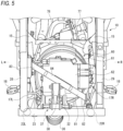
FIG. 5 is a rear view of the vehicle body central portion according to the present embodiment. - IG. 6 is a right side view of the vehicle body central portion according to the present embodiment.
- A straddle-type vehicle according to an aspect of the present invention travels using gas fuel. The frame of the vehicle body of the straddle-type vehicle is formed by a vehicle body frame, and a gas tank is provided inside the vehicle body frame. In the vehicle body frame, a pair of frame portions are located on the lateral side of the gas tank, and a bridge portion that connects the pair of frame portions is located at the rear side of the gas tank. The fixing position of one end portion of the bridge portion and one frame portion is lower than the fixing position of the other end portion of the bridge portion and the other frame portion, and the bridge portion obliquely crosses the rear side of the gas tank. Even if a plurality of components are arranged at the rear side of the gas tank in the left-right direction or the upper-lower direction, the bridge portion is positioned between the plurality of components and the gas tank. When the components move forward due to an impact or the like from the rear side, the gas tank is protected from the components by the bridge portion. Accordingly, the gas tank and the components are brought close to each other, and the gas tank and the components are compactly provided to reduce the size of the straddle-type vehicle.
- Hereinafter, a straddle-type vehicle according to the present embodiment will be described with reference to the accompanying drawings.
FIG. 1 is a left side view of a vehicle internal structure according to the present embodiment.FIG. 2 is a right side view of the vehicle internal structure according to the present embodiment. In the following drawings, an arrow Fr indicates the vehicle front side, an arrow Re indicates the vehicle rear side, an arrow L indicates the vehicle left side, and an arrow R indicates the vehicle right side. - As shown in
FIGS. 1 and2 , a straddle-type vehicle 1 is implemented by mounting various covers (not shown), as vehicle body exteriors, on avehicle body frame 10 forming the frame of the vehicle body. Ahead pipe 11 is provided at the front end portion of thevehicle body frame 10, and asupport frame 12 extends obliquely rearward and downward from the upper portion of thehead pipe 11. A pair offirst down frames 13 branch to the left and right from the lower portion of thesupport frame 12 and extend downward, and a pair of second downframes 14 branch to the left and right from the lower portion of thehead pipe 11 and extend downward. A pair ofmain frames 15 are connected to the lower portions of the pair offirst down frames 13 and the pair of seconddown frames 14. - The pair of
main frames 15 extend toward the vehicle rear side, and the intermediate portions of the pair ofmain frames 15 are connected to each other by anupper bridge 16. A pair of left-rightasymmetric side frames 17 extend downward from the front ends of the pair ofmain frames 15. Theside frames 17 are bent rearward at the lower portion of the vehicle, and then extend obliquely rearward and upward toward the rear portions of the pair ofmain frames 15. The front half portion of thevehicle body frame 10 is formed in a cradle shape by the pair ofmain frames 15 and the pair ofside frames 17. A pair offoot boards 18 are attached to the pair ofside frames 17. - A pair of
seat frames 19 extend rearward from the rear portions of the pair ofmain frames 15. The facing interval of the pair ofseat frames 19 increases toward the middle of the frames, and then decreases toward the rear ends of the frames. The pair ofseat frames 19 are formed in an arch shape, and the rear end portions of the pair ofseat frames 19 are connected to each other. The front portions of the pair ofseat frames 19 are connected to each other by anupper bridge 21. A rear portion of the pair ofside frames 17 is connected to theupper bridge 21, and theupper bridge 21 is supported from the lower side by the pair ofside frames 17. - A pair of left-right asymmetric
lower frames 22 extend rearward from the lower portions of the pair ofside frames 17. The rear end portions of the pair oflower frames 22 are connected to each other by alower bridge 23. Aleft sub frame 28 extends obliquely rearward and upward from the left end portion of thelower bridge 23, and theseat frame 19 is supported by theleft sub frame 28 from below. The right end portion of thelower bridge 23 and the intermediate portion of theright side frame 17 are connected to each other by aside bridge 25. Aright sub frame 29 extends obliquely rearward and upward from the intermediate portion of theside bridge 25, and theseat frame 19 is supported by theright sub frame 29 from below. - A
front fork 33 is steerably supported on thehead pipe 11, and afront wheel 34 is rotatably supported on the lower portion of thefront fork 33. Along gas tank 60 is provided inside the cradle portion in the front half portion of thevehicle body frame 10. Gas fuel such as hydrogen is stored in thegas tank 60, and atank valve 62 at the rear portion of the tank controls inflow and outflow of the gas fuel. The gas fuel is supplied from thetank valve 62 toward an injector (not shown) above a unit swing engine (an engine) 41 via fuel system components such as a plurality of pipes, aregulator 64, and afuel hose 66. - The
unit swing engine 41 is swingably supported onsupport plates 31 of theleft sub frame 28 and theright sub frame 29. Theunit swing engine 41 is operated by the combustion energy of the gas fuel supplied from thegas tank 60. The cylinder axis of theunit swing engine 41 is inclined forward to be close to horizontal, and acylinder assembly 43 extends forward of the vehicle from acrankcase 42. Thecylinder assembly 43 enters between theleft sub frame 28 and theright sub frame 29, and the front end of thecylinder assembly 43 is close to thetank valve 62 of thegas tank 60. - An intake system component such as an
air cleaner 51 is connected to the upper portion of thecylinder assembly 43, and an exhaust system component such as anexhaust pipe 56 or amuffler 58 is connected to the lower portion of thecylinder assembly 43. ACVT cover 47 is attached to the left side of thecrankcase 42. Arear wheel 35 is rotatably supported on the rear portion of theCVT cover 47. A belt-type continuously variable transmission (not shown) is accommodated inside theCVT cover 47, and the driving force of theunit swing engine 41 is transmitted to therear wheel 35 via a belt. Theunit swing engine 41 is swung together with themuffler 58, theCVT cover 47, and therear wheel 35. - The straddle-type vehicle 1 is provided with a protective member that protects the
gas tank 60 from other components when receiving an impact from the rear side. On the rear side of thegas tank 60, not only acylinder head cover 46 of theunit swing engine 41 but also alink mechanism 37 for thesuspension 36 is provided. Since thelink mechanism 37 is located below thecylinder head cover 46, thegas tank 60 cannot be appropriately protected by the protective member that extends only in the left-right direction. Therefore, in the present embodiment, a protection bridge (a bridge portion) 81 serving as a protective member is inclined diagonally in the left-right direction, thereby effectively protecting thegas tank 60 from a plurality of components that are arranged in the upper-lower direction. - The peripheral structure of the unit swing engine will be described with reference to
FIGS. 3 and4 .FIG. 3 is a left side view of a vehicle body central portion according to the present embodiment.FIG. 4 is a top view of the vehicle body central portion according to the present embodiment. - As shown in
FIGS. 3 and4 , thecylinder assembly 43 of theunit swing engine 41 is formed by stacking acylinder 44, acylinder head 45, and acylinder head cover 46. An intake device is provided above thecylinder head 45. The intake device includes theair cleaner 51, aU-shaped outlet tube 52, athrottle body 53, and anintake pipe 54. Air is sent from theair cleaner 51 to thethrottle body 53 through theoutlet tube 52, and the intake amount is adjusted by thethrottle body 53, then the air is supplied to the intake port of thecylinder head 45 through theintake pipe 54. - An exhaust port is formed in the lower portion of the
cylinder head 45, and theexhaust pipe 56 serving as an exhaust device is connected to the exhaust port. Theexhaust pipe 56 is curved rearward from the lower surface of thecylinder head 45 and then extends to the vehicle rear side through the right side of thecrankcase 42. The muffler 58 (seeFIG. 2 ) inclined obliquely rearward and upward at the right side of therear wheel 35 is connected to the rear end portion of theexhaust pipe 56. The exhaust gas flows into theexhaust pipe 56 from the exhaust port of theunit swing engine 41, flows rearward through theexhaust pipe 56, and then is discharged to the outside from themuffler 58. - A
link mechanism 37 for thesuspension 36 is provided below thecylinder head 45. Thelink mechanism 37 includes alink lever 38 having an arc shape in the side view, and the intermediate portion of thelink lever 38 is swingably coupled to alink bracket 32 of thevehicle body frame 10. The upper end portion of thelink lever 38 is swingably coupled to the lower portion of thecrankcase 42 via alink arm 39, and the lower end portion of thelink lever 38 is coupled to asuspension bracket 75 of thevehicle body frame 10 via thesuspension 36. Thesuspension 36 expands and contracts as theunit swing engine 41 swings, thereby absorbing vibrations transmitted to the vehicle body. - The
gas tank 60 is provided in front of theunit swing engine 41. A tankmain body 61 of thegas tank 60 is formed in a cylindrical shape, and both end portions of the tankmain body 61 bulge in a hemispherical shape. The longitudinal direction of the tankmain body 61 is oriented in the front-rear direction, and the front end of the tankmain body 61 is slightly inclined to be higher than the rear end. Thegas tank 60 is supported on the lower portion of thevehicle body frame 10 via a pair offront tank bracket 71 andrear tank bracket 72.Bands tank brackets main body 61 is fastened by thebands - The
tank valve 62 is provided at the rear end portion of the tankmain body 61, and theregulator 64 is connected to arelief valve pipe 63 extending obliquely rearward and upward from the lower portion of thetank valve 62. When the pressure of the gas fuel reaches a predetermined pressure or higher, the valve of theregulator 64 is opened to adjust the pressure of the gas fuel. Afuel filling port 77 is formed above thegas tank 60, and the upper portion of thetank valve 62 is connected to a fillingpipe 78 that extends obliquely downward and rearward from thefuel filling port 77. The tank is filled with the gas fuel from thefuel filling port 77 through thetank valve 62. Aradiator 30 for engine cooling is provided in front of thegas tank 60. - An injector joint 68 is connected to the
regulator 64 via anupstream pipe 65, thefuel hose 66, and adownstream pipe 67. Theupstream pipe 65 and thedownstream pipe 67 are formed of a hard pipe material such as metal, and thefuel hose 66 is formed of a soft rubber hose. Theupstream pipe 65 crosses below thetank valve 62 and extends from theregulator 64 at the vehicle body left side to the vehicle body right side. At the vehicle body right side, the lower end portion of thefuel hose 66 is connected to theupstream pipe 65, and thefuel hose 66 extends upward through the right side of thegas tank 60. The upper end portion of thefuel hose 66 is connected to the injector joint 68 above thecylinder head 45 via thedownstream pipe 67. - In this way, the gas fuel is supplied from the
tank valve 62 of thegas tank 60 to theunit swing engine 41 through therelief valve pipe 63, theregulator 64, theupstream pipe 65, thefuel hose 66, and thedownstream pipe 67. Aprotection bridge 81 that connects the rightlower frame 22 and theleft side frame 17 is provided at the rear side of thetank valve 62. Theprotection bridge 81 extends obliquely so as to avoid theregulator 64 and thelink mechanism 37. When the straddle-type vehicle 1 receives an impact from the rear side, thetank valve 62 is protected from the rear side component such as thelink mechanism 37 by theprotection bridge 81. - The protection structure of the gas tank will be described with reference to
FIGS. 5 and6 .FIG. 5 is a rear view of the vehicle body central portion according to the present embodiment.FIG. 6 is a right side view of the vehicle body central portion according to the present embodiment.FIG. 5 shows a state in which the unit swing engine, the intake device, the exhaust device, and the like are removed. In the following description, the side frame and the lower frame on the left side are denoted by a reference sign L, and the side frame and the lower frame on the right side are denoted by a reference sign R. - As shown in
FIG. 5 , a pair of frame portions of thevehicle body frame 10 are located on both sides of thegas tank 60, and the pair of frame portions are formed left-right asymmetrically by a pair ofside frames lower frames left side frame 17L rises behind the rear side portion of theright side frame 17R, and the rightlower frame 22R is formed longer than the leftlower frame 22L in the front-rear direction (seeFIGS. 1 and2 ). Theprotection bridge 81 that obliquely crosses the rear side of thegas tank 60 is connected to the pair of frame portions. - More specifically, an L-shaped
fixing plate 82 is provided at the right end portion of theprotection bridge 81, and avertical fixing plate 83 is provided at the left end portion of theprotection bridge 81. The fixingplate 82 on the right end side of theprotection bridge 81 is fixed to the rightlower frame 22R, and the fixingplate 82 on the left end side of theprotection bridge 81 is fixed to the rising rear side portion of theleft side frame 17L. The fixing position of the right end portion of theprotection bridge 81 and the rightlower frame 22R is lower than the fixing position of the left end portion of theprotection bridge 81 and theleft side frame 17L. Theprotection bridge 81 extends obliquely, so that interference between theprotection bridge 81 and the regulator 64 (seeFIG. 3 ) is prevented. - The
protection bridge 81 is located between thegas tank 60 and thelink mechanism 37, and thelink mechanism 37 partially overlaps the intermediate position of theprotection bridge 81 when viewed from the rear. Thelink mechanism 37 is provided close to theprotection bridge 81 in the front-rear direction, and thegas tank 60 and thelink mechanism 37 are compactly provided. The rear surface of the intermediate position of theprotection bridge 81 is recessed, and arecess 84 is formed along the extending direction of theprotection bridge 81. Therecess 84 of theprotection bridge 81 is positioned in front of thelink mechanism 37. Accordingly, even if thelink lever 38 of thelink mechanism 37 swings, the interference between theprotection bridge 81 and thelink lever 38 is prevented. - In addition to the
link mechanism 37, the cylinder head cover 46 (seeFIG. 6 ) is also located at the rear side of theprotection bridge 81, and theprotection bridge 81 overlaps thelink mechanism 37 and thecylinder head cover 46 when viewed from the rear. Therefore, even when thelink mechanism 37 and thecylinder head cover 46 move forward due to an impact or the like from the rear side, thelink mechanism 37 and thecylinder head cover 46 are received by theprotection bridge 81, and thegas tank 60 is protected. Accordingly, thegas tank 60, thelink mechanism 37, and theunit swing engine 41 can be compactly provided in thevehicle body frame 10, thereby reducing the size of the straddle-type vehicle 1. - As shown in
FIG. 6 , atriangular frame 20 is formed on the right (one) frame portion of thevehicle body frame 10 by a lower side portion that extends in the front-rear direction, a front oblique side portion that extends obliquely upward and rearward from the front end of the lower side portion, and a rear oblique side portion that extends obliquely upward and forward from the rear end of the lower side portion. The lower side portion of thetriangular frame 20 is formed by the rightlower frame 22R, the front oblique side portion of thetriangular frame 20 is formed by theright side frame 17R, and the rear oblique side portion of thetriangular frame 20 is formed by theright side bridge 25. The fixingplate 82 on the right end side of theprotection bridge 81 is fixed to thelower frame 22R serving as the lower side portion of thetriangular frame 20. - The
triangular frame 20 has high rigidity, and thetriangular frame 20 is less likely to be deformed even when receiving an impact or the like from the rear side. Theprotection bridge 81 is fixed to thetriangular frame 20, so that displacement of the fixing position on the right end side of theprotection bridge 81 is prevented. In particular, theprotection bridge 81 is fixed to thelower frame 22R that has high rigidity in the front-rear direction. Accordingly, even if an impact or the like is received from the rear side, the displacement of the fixing position on the right end side of theprotection bridge 81 is effectively prevented. Therefore, thegas tank 60 is protected from the rear components such as thelink mechanism 37 and thecylinder head cover 46 by theprotection bridge 81. - As shown in
FIG. 3 , theside frame 17L and theleft sub frame 28 are connected to the left (the other) frame portion of thevehicle body frame 10 by aside bridge 26, and theside frame 17L and themain frame 15 are connected to each other by aside bridge 27. By the side bridges 26 and 27, the rigidity of theside frame 17L is increased, and theside frame 17L is less likely to be deformed. Theprotection bridge 81 is fixed to theside frame 17L, so that the displacement of the fixing position on the left end side of theprotection bridge 81 is prevented even when an impact from the rear side is received, and thegas tank 60 is protected from various rear components by theprotection bridge 81. - As described above, according to the straddle-type vehicle 1 in the present embodiment, the
protection bridge 81 obliquely crosses the rear side of thegas tank 60 such that the right end portion of theprotection bridge 81 is lower than the left end portion. Even if thelink mechanism 37 and thecylinder head cover 46 are arranged at the rear side of thegas tank 60 in the upper-lower direction, theprotection bridge 81 is positioned between thelink mechanism 37 and thecylinder head cover 46 and thegas tank 60. When thelink mechanism 37 and the like move forward due to an impact or the like from the rear side, thegas tank 60 is protected from thelink mechanism 37 and the like by theprotection bridge 81. Accordingly, thegas tank 60, thelink mechanism 37, and the like are brought close to each other, and thegas tank 60, thelink mechanism 37, and the like are compactly provided to reduce the size of the straddle-type vehicle 1. - In the present embodiment, the triangular frame is formed on one frame portion of the vehicle body frame, but the frame shape of the vehicle body frame is not particularly limited. For example, the triangular frame may be formed on the other frame portion, or the triangular frame may be formed on both the left and right frame portions. The location where the protection bridge is fixed to the triangular frame is not particularly limited.
- Although it is not necessary for the triangular frame to be formed on both the left and right frame portions, it is preferable that the lower portion of the one frame portion is formed by the lower frame and one end portion of the protection bridge is fixed to this lower frame.
- In the present embodiment, the fixing position of the right end portion of the protection bridge is lower than the fixing position of the left end portion of the protection bridge. Alternatively, the fixing position of the right end portion of the protection bridge may be higher than the fixing position of the left end portion of the protection bridge. For example, the right end portion of the protection bridge may be fixed to the rear side portion of the right side frame, and the left end portion of the protection bridge may be fixed to the left lower frame.
- In the present embodiment, the link mechanism and the cylinder head cover are positioned at the rear side of the protection bridge, but the components at the rear side of the protection bridge are not particularly limited. Another component such as a regulator may be positioned at the rear side of the protection bridge.
- The unit swing engine is exemplified as an engine in the present embodiment. However, the engine is not limited to the unit swing engine as long as the engine is operated by the combustion energy of the gas fuel.
- The engine is a hydrogen engine using hydrogen gas in the present embodiment. Alternatively, the engine may be other gas fuel engines using other gas fuel such as a methane gas and a propane gas.
- A single gas tank is provided in the straddle-type vehicle in the present embodiment. Alternatively, a plurality of gas tanks may be provided in the straddle-type vehicle.
- Both end portions of the gas tank are formed in a cylindrical shape bulging in a hemispherical shape in the present embodiment. However, the shape of the gas tank is not limited as long as the gas tank has a shape capable of storing the gas fuel.
- Further, the protection bridge according to the present embodiment is not limited to being used in the above-described straddle-type vehicle, and may be used in other types of straddle-type vehicles. The straddle-type vehicle is not limited to a general vehicle in which the driver rides on the seat in a posture of straddling the seat, and includes a scooter-type vehicle in which the driver rides on the seat without straddling the seat.
- As described above, a first aspect provides a straddle-type vehicle (1) for traveling using gas fuel, the straddle-type vehicle including: a vehicle body frame (10) that forms a frame of a vehicle body; and a gas tank (60) inside the vehicle body frame, in which the vehicle body frame includes a pair of frame portions (side frames 17L and 17R, and
lower frames - A second aspect is directed to the first aspect, in which a lower portion of the one frame portion is formed by a lower side portion that extends in a front-rear direction, and in which the one end portion of the bridge portion is fixed to the lower side portion of the one frame portion. According to this configuration, since the bridge portion is fixed to the lower side portion of the frame portion that has high rigidity in the front-rear direction, the lower side portion is less likely to be deformed due to an impact or the like from the rear side, and the displacement of the fixing position of the one end portion of the bridge portion can be prevented.
- A third aspect is directed to the first aspect, in which a triangular frame (20) is formed on the one frame portion by a lower side portion (a
lower frame 22R) that extends in a front-rear direction, a front oblique side portion (aside frame 17R) that extends obliquely upward and rearward from a front end of the lower side portion, and a rear oblique side portion (a side bridge 25) that extends obliquely upward and forward from a rear end of the lower side portion, and in which the one end portion of the bridge portion is fixed to the triangular frame. According to this configuration, since the bridge portion is fixed to the triangular frame that has high rigidity, the triangular frame is less likely to be deformed due to an impact from the rear side, and the displacement of the fixing position of the one end portion of the bridge portion can be prevented. - A fourth aspect is directed to the third aspect, in which the one end portion of the bridge portion is fixed to the lower side portion of the one frame portion. According to this configuration, since the bridge portion is fixed to the lower side portion of the frame portion that has high rigidity in the front-rear direction, the lower side portion is less likely to be deformed due to an impact or the like from the rear side, and the displacement of the fixing position of the one end portion of the bridge portion can be prevented.
- The straddle-type vehicle according to a fifth aspect directed to any one of the first to fourth aspects, further including a suspension (36) configured to absorb vibration of the vehicle body, and a link mechanism (37) for the suspension, in which the link mechanism is located at a rear side of the gas tank, and in which the bridge portion is located between the gas tank and the link mechanism. According to this configuration, even when the link mechanism moves forward due to an impact from the rear side, the gas tank is protected from the link mechanism by the bridge portion. Accordingly, the gas tank and the link mechanism can be compactly provided, and the size of the straddle-type vehicle can be reduced.
- Although the present embodiment has been described, a part or all of the above-described embodiment and modifications may be combined as another embodiment.
- The technique according to the present disclosure is not limited to the above-described embodiment, and may be variously changed, replaced, or modified without departing from the gist of the technical concept. Further, the present invention may be implemented by other methods as long as the technical concept can be implemented by the methods through advance of the technique or other derivative techniques. Therefore, the claims cover all embodiments that may fall within the scope of the technical concept.
-
- 1: straddle-type vehicle
- 10: vehicle body frame
- 17: side frame (frame portion)
- 17R: side frame (front oblique side portion)
- 20: triangular frame
- 22: lower frame (frame portion)
- 22R: lower frame (lower side portion)
- 25: side bridge (rear oblique side portion)
- 36: suspension
- 37: link mechanism
- 60: gas tank
- 81: protection bridge (bridge portion)
Claims (5)
- A straddle-type vehicle (1) for traveling using gas fuel, the straddle-type vehicle comprising:a vehicle body frame (10) that forms a frame of a vehicle body; anda gas tank (60) inside the vehicle body frame,wherein the vehicle body frame includes: a pair of frame portions (17L, 17R, 22L, 22R) that are located on both sides of the gas tank; and a bridge portion (81) that connects the pair of frame portions at a rear side of the gas tank, andwherein a fixing position of one end portion of the bridge portion and one frame portion is lower than a fixing position of the other end portion of the bridge portion and the other frame portion.
- The straddle-type vehicle according to claim 1,wherein a lower portion of the one frame portion is formed by a lower side portion that extends in a front-rear direction, andwherein the one end portion of the bridge portion is fixed to the lower side portion of the one frame portion.
- The straddle-type vehicle according to claim 1,wherein a triangular frame is formed on the one frame portion by a lower side portion that extends in a front-rear direction, a front oblique side portion that extends obliquely upward and rearward from a front end of the lower side portion, and a rear oblique side portion that extends obliquely upward and forward from a rear end of the lower side portion, andwherein the one end portion of the bridge portion is fixed to the triangular frame.
- The straddle-type vehicle according to claim 3,
wherein the one end portion of the bridge portion is fixed to the lower side portion of the one frame portion. - The straddle-type vehicle according to claim 1 or 2, further comprisinga suspension configured to absorb vibration of the vehicle body, anda link mechanism for the suspension,wherein the link mechanism is located at a rear side of the gas tank, andwherein the bridge portion is located between the gas tank and the link mechanism.
Applications Claiming Priority (1)
| Application Number | Priority Date | Filing Date | Title |
|---|---|---|---|
| JP2023182039A JP2025071669A (en) | 2023-10-23 | 2023-10-23 | Saddle-type vehicle |
Publications (1)
| Publication Number | Publication Date |
|---|---|
| EP4545388A1 true EP4545388A1 (en) | 2025-04-30 |
Family
ID=93150244
Family Applications (1)
| Application Number | Title | Priority Date | Filing Date |
|---|---|---|---|
| EP24206978.9A Pending EP4545388A1 (en) | 2023-10-23 | 2024-10-16 | STRAT-SEAT VEHICLE |
Country Status (2)
| Country | Link |
|---|---|
| EP (1) | EP4545388A1 (en) |
| JP (1) | JP2025071669A (en) |
Citations (5)
| Publication number | Priority date | Publication date | Assignee | Title |
|---|---|---|---|---|
| JPH07144672A (en) * | 1993-11-22 | 1995-06-06 | Suzuki Motor Corp | Gas fuel filling device for gas fuel type scooter type vehicle |
| US20080093148A1 (en) * | 2006-10-18 | 2008-04-24 | Yamaha Hatsudoki Kabushiki Kaisha | Electric two-wheeled vehicle |
| JP2011195095A (en) * | 2010-03-23 | 2011-10-06 | Honda Motor Co Ltd | Hydrogen cylinder mounting structure of fuel cell vehicle |
| US20140353061A1 (en) * | 2013-06-04 | 2014-12-04 | Suzuki Motor Corporation | Fuel-cell vehicle |
| EP2574487B1 (en) * | 2011-09-28 | 2019-02-20 | Suzuki Motor Corporation | Motorcycle |
-
2023
- 2023-10-23 JP JP2023182039A patent/JP2025071669A/en active Pending
-
2024
- 2024-10-16 EP EP24206978.9A patent/EP4545388A1/en active Pending
Patent Citations (5)
| Publication number | Priority date | Publication date | Assignee | Title |
|---|---|---|---|---|
| JPH07144672A (en) * | 1993-11-22 | 1995-06-06 | Suzuki Motor Corp | Gas fuel filling device for gas fuel type scooter type vehicle |
| US20080093148A1 (en) * | 2006-10-18 | 2008-04-24 | Yamaha Hatsudoki Kabushiki Kaisha | Electric two-wheeled vehicle |
| JP2011195095A (en) * | 2010-03-23 | 2011-10-06 | Honda Motor Co Ltd | Hydrogen cylinder mounting structure of fuel cell vehicle |
| EP2574487B1 (en) * | 2011-09-28 | 2019-02-20 | Suzuki Motor Corporation | Motorcycle |
| US20140353061A1 (en) * | 2013-06-04 | 2014-12-04 | Suzuki Motor Corporation | Fuel-cell vehicle |
Also Published As
| Publication number | Publication date |
|---|---|
| JP2025071669A (en) | 2025-05-08 |
Similar Documents
| Publication | Publication Date | Title |
|---|---|---|
| US8584788B2 (en) | Exhaust system for motorcycle | |
| US20090322069A1 (en) | Vehicle with rotatable fuel tank | |
| CN102770332A (en) | Evaporated fuel control device for saddle-type vehicles | |
| CN101468699B (en) | Miniature vehicle | |
| JP5719256B2 (en) | Motorcycle | |
| TWI570005B (en) | Electrical component mounting structure for saddle-riding type vehicle | |
| EP4385867A1 (en) | Gas tank of straddle-type vehicle with swing engine | |
| CN103204206B (en) | Straddle type vehicle | |
| CN101195397A (en) | Vehicle fuel pump arrangement | |
| JP6149705B2 (en) | Motorcycle exhaust system | |
| JP2008230492A (en) | Motorcycle fuel supply system | |
| CN101172505B (en) | Automotive tumbrel | |
| CN103003137B (en) | Scooter type motorcycle | |
| EP4545387A1 (en) | STRAT-SEAT VEHICLE | |
| EP4512707A1 (en) | Straddle-type vehicle | |
| CN217893100U (en) | Electrical component arrangement structure | |
| JP4144383B2 (en) | Fuel supply device for saddle riding type vehicle | |
| JP2025071669A (en) | Saddle-type vehicle | |
| CN215794229U (en) | Fuel pipe support structure for saddle-ride type vehicle | |
| JP3585232B2 (en) | Motorcycles and tricycles | |
| JP2013067271A (en) | Canister arranging structure of saddle riding type vehicle | |
| JP2025071667A (en) | Saddle-type vehicle | |
| JP2026011103A (en) | Saddle-type vehicle | |
| JP2001138975A (en) | Motorcycles and tricycles | |
| JP3917980B2 (en) | Motorcycle / Tricycle |
Legal Events
| Date | Code | Title | Description |
|---|---|---|---|
| PUAI | Public reference made under article 153(3) epc to a published international application that has entered the european phase |
Free format text: ORIGINAL CODE: 0009012 |
|
| STAA | Information on the status of an ep patent application or granted ep patent |
Free format text: STATUS: REQUEST FOR EXAMINATION WAS MADE |
|
| 17P | Request for examination filed |
Effective date: 20241016 |
|
| AK | Designated contracting states |
Kind code of ref document: A1 Designated state(s): AL AT BE BG CH CY CZ DE DK EE ES FI FR GB GR HR HU IE IS IT LI LT LU LV MC ME MK MT NL NO PL PT RO RS SE SI SK SM TR |