EP4545356A1 - Control device for bed movement systems - Google Patents
Control device for bed movement systems Download PDFInfo
- Publication number
- EP4545356A1 EP4545356A1 EP24206358.4A EP24206358A EP4545356A1 EP 4545356 A1 EP4545356 A1 EP 4545356A1 EP 24206358 A EP24206358 A EP 24206358A EP 4545356 A1 EP4545356 A1 EP 4545356A1
- Authority
- EP
- European Patent Office
- Prior art keywords
- encoder
- gearmotor
- shaft
- rotor
- tubular body
- Prior art date
- Legal status (The legal status is an assumption and is not a legal conclusion. Google has not performed a legal analysis and makes no representation as to the accuracy of the status listed.)
- Granted
Links
Images



Classifications
-
- B—PERFORMING OPERATIONS; TRANSPORTING
- B60—VEHICLES IN GENERAL
- B60P—VEHICLES ADAPTED FOR LOAD TRANSPORTATION OR TO TRANSPORT, TO CARRY, OR TO COMPRISE SPECIAL LOADS OR OBJECTS
- B60P3/00—Vehicles adapted to transport, to carry or to comprise special loads or objects
- B60P3/32—Vehicles adapted to transport, to carry or to comprise special loads or objects comprising living accommodation for people, e.g. caravans, camping, or like vehicles
- B60P3/36—Auxiliary arrangements; Arrangements of living accommodation; Details
- B60P3/38—Sleeping arrangements, e.g. living or sleeping accommodation on the roof of the vehicle
- B60P3/39—Sleeping arrangements, e.g. living or sleeping accommodation on the roof of the vehicle expansible, collapsible or repositionable elements adapted to support a bed, e.g. wall portions
-
- H—ELECTRICITY
- H02—GENERATION; CONVERSION OR DISTRIBUTION OF ELECTRIC POWER
- H02K—DYNAMO-ELECTRIC MACHINES
- H02K11/00—Structural association of dynamo-electric machines with electric components or with devices for shielding, monitoring or protection
- H02K11/20—Structural association of dynamo-electric machines with electric components or with devices for shielding, monitoring or protection for measuring, monitoring, testing, protecting or switching
- H02K11/21—Devices for sensing speed or position, or actuated thereby
-
- H—ELECTRICITY
- H02—GENERATION; CONVERSION OR DISTRIBUTION OF ELECTRIC POWER
- H02K—DYNAMO-ELECTRIC MACHINES
- H02K7/00—Arrangements for handling mechanical energy structurally associated with dynamo-electric machines, e.g. structural association with mechanical driving motors or auxiliary dynamo-electric machines
- H02K7/10—Structural association with clutches, brakes, gears, pulleys or mechanical starters
- H02K7/116—Structural association with clutches, brakes, gears, pulleys or mechanical starters with gears
- H02K7/1163—Structural association with clutches, brakes, gears, pulleys or mechanical starters with gears where at least two gears have non-parallel axes without having orbital motion
- H02K7/1166—Structural association with clutches, brakes, gears, pulleys or mechanical starters with gears where at least two gears have non-parallel axes without having orbital motion comprising worm and worm-wheel
-
- H—ELECTRICITY
- H02—GENERATION; CONVERSION OR DISTRIBUTION OF ELECTRIC POWER
- H02K—DYNAMO-ELECTRIC MACHINES
- H02K7/00—Arrangements for handling mechanical energy structurally associated with dynamo-electric machines, e.g. structural association with mechanical driving motors or auxiliary dynamo-electric machines
- H02K7/14—Structural association with mechanical loads, e.g. with hand-held machine tools or fans
Definitions
- the present invention relates to a control device for bed handling systems installed in vehicles such as campers and similar so-called recreational vehicles.
- beds can be installed that can assume a lowered use position and a raised position for storage, connected to systems that allow their movement between said positions.
- Such systems generally involve the use of belts to which a structure that constitutes the base of a bed is connected.
- the bed base is raised to the storage position or lowered to the position of use by means of the belts to which it is connected.
- Suitable electric actuators allow the movement of the bed to be controlled by means of the belts which are configured so as to wind on corresponding shafts, rotated by said actuators, and respectively unwind, to move the bed thanks to the clockwise or anticlockwise rotation of the same shafts.
- guides are provided on the walls of the vehicle where the bed is installed, whose function is to stabilize the vertical movements of lowering and lifting of the bed thanks to specific carriages that slide on the guides on one side and are connected to the base of the bed or to the belts on another side.
- the present invention aims, in particular, to provide a device that can be used to control the electric actuators by which the winding/unwinding shafts of the bed base lifting/lowering belts bed are operated.
- the present invention it is possible to install the control encoder in a more favorable configuration, both from a functional point of view and from an operational and constructional point of view, also improving the reliability of the control provided by the encoder.
- the construction simplicity of the present device implies also a reduction of the production costs.
- the installation of the device, as well as the accessibility to the relative adjustment members and the necessary wiring, are simplified.
- a control device in accordance with the present invention can be used to control a movement system of the type shown in Fig. 1 , i.e. of the type comprising a plurality of belts 1 driven by an electric gearmotor 2 as further described below and connected to a bed base 3 (a slatted base in the exemplary drawing of Fig. 1 ).
- a mattress can be placed on the base 3.
- the electric gearmotor 2 controls the raising and lowering of the base 3.
- one end of each belt 1 is constrained to a bracket 4 anchored to the bed base 3, and each belt slides on a roller 5 which, in turn, is constrained to a fixed point 6.
- each belt 1 is constrained to a shaft 7 driven by the electric gearmotor.
- the electric gearmotor 2 determines the lifting S and the lowering A of the bed base 3.
- vertical guides 8 are provided, fixed on a wall of the vehicle in the bed installation area, which guide the vertical movement of the bed base 3.
- carriages 9 are mounted on one side of the bed base 3 facing the guides 8, which act as an interface element between the guides 8 and the bed base 3, facilitating and stabilising the vertical movement of the latter.
- the electric gearmotor 2 is controlled by a programmable encoder 10 that allows to detect the direction of rotation and the angular movements of the output shaft of the electric gearmotor itself, also acting as a position transducer and controlling the upper and lower stop points, i.e. the lifting and lowering positions of the bed.
- the present invention applies to bed handling systems installed in vehicles such as campers and similar so-called recreational vehicles in which a bed base is moved by an electric gearmotor controlled by an encoder.
- the electric gearmotor 2 has a first output 27 on which the shaft 7 for winding/unwinding the belts 1 is engaged and a second output 210 on which the rotor of the encoder 10 is engaged.
- the second output 210 consists of a power take-off.
- Said outputs 27, 210 are formed on the output side 20 of the gearmotor 2.
- the outputs 27, 210 are synchronous and are both on the same output side 20 of the gearmotor 2. In other words, between the outputs 27, 210 there are no mechanical transmissions or speed reduction devices.
- said outputs 27, 210 are coaxial with each other.
- screw connections 21 are provided on the aforementioned body 20 to allow its fastening to a support bracket 22 that, in turn, can be fastened to a wall of the vehicle in the bedinstallation area .
- a further bracket 23 acts as a support for the shaft 7 which substantially extends between the brackets 22 and 23.
- a bracket 14 can be used to fasten the encoder 10, bracket which has aplurality of arms 140 (for example, two in number) that on one side are fixed by screws to the output side 20 of the gearmotor 2 and on the opposite side are joined together by a ring 141 fastened to an external side of the encoder stator.
- the arms 140 of the bracket 14 are external with respect to the aforementioned tubular body 12.
- the structural configuration described above allows the encoder 10 to be arranged axially aligned with the shaft 7 for winding/unwinding the belts 1 according to an operational arrangement that avoids the interposition of transmissions between the output of the gearmotor and the encoder and also avoids connecting the encoder 10 to the shaft 7, so that the encoder 10 is directly connected to the output of the gearmotor 2, allowing greater precision in the detection of the angular position of the shaft 7 and a more functional installation of the encoder itself.
- the shaft 7 is connected to the output 27 of the gearmotor and the rotor of the encoder 10 is connected to the shaft 7, on the side opposite to said output 27.
- the rotor of the encoder 10 is axially aligned with the output 27 of the gearmotor 2.
- the coupling of the encoder rotor with the output of the gearmotor is direct
- such coupling is indirect, in the sense that the shaft 7 is interposed between the output of the gearmotor and the rotor of the encoder.
- the encoder rotor can be connected to the member that drives it into rotation (in this case the shaft 7) by means of a rigid tubular body 12 which on one side has an axial appendage 120 configured, in this example, to be coupled axially with the shaft 7.
- this coupling can be achieved by coupling the appendage 120 of the body 12 with a corresponding axial appendage 72 of the shaft 7.
- the arms of the bracket 14 can be fixed to the bracket 23.
- a device in accordance with the present invention is a control device for bed handling systems installed in vehicles such as campers and similar so-called recreational vehicles comprising a gearmotor 2 which controls the rotation of a shaft 7 on which are attached belts 1 to which a bed base 3 is connected, wherein the rotation of the shaft 7 controlled by the gearmotor 2 in one direction or in the opposite direction causes the bed base 3 to be raised or lowered by means of the belts 1, wherein there isan encoder 10 configured to detect one or more parameters related to the rotation of said shaft 7, wherein said encoder has a rotor 101 and a stator 102, and wherein the rotor 101 of the encoder is arranged coaxially with an output 27 of the gearmotor 2 and with said shaft 7.
Landscapes
- Engineering & Computer Science (AREA)
- Power Engineering (AREA)
- Microelectronics & Electronic Packaging (AREA)
- Health & Medical Sciences (AREA)
- Public Health (AREA)
- Transportation (AREA)
- Mechanical Engineering (AREA)
- Connection Of Motors, Electrical Generators, Mechanical Devices, And The Like (AREA)
- Invalid Beds And Related Equipment (AREA)
Abstract
Description
- The present invention relates to a control device for bed handling systems installed in vehicles such as campers and similar so-called recreational vehicles.
- It is known that in vehicles such as campers, beds can be installed that can assume a lowered use position and a raised position for storage, connected to systems that allow their movement between said positions.
- Such systems generally involve the use of belts to which a structure that constitutes the base of a bed is connected. The bed base is raised to the storage position or lowered to the position of use by means of the belts to which it is connected. Suitable electric actuators allow the movement of the bed to be controlled by means of the belts which are configured so as to wind on corresponding shafts, rotated by said actuators, and respectively unwind, to move the bed thanks to the clockwise or anticlockwise rotation of the same shafts. Normally, guides are provided on the walls of the vehicle where the bed is installed, whose function is to stabilize the vertical movements of lowering and lifting of the bed thanks to specific carriages that slide on the guides on one side and are connected to the base of the bed or to the belts on another side.
- The present invention aims, in particular, to provide a device that can be used to control the electric actuators by which the winding/unwinding shafts of the bed base lifting/lowering belts bed are operated.
- This result has been achieved, in accordance with the present invention, by adopting the idea of realizing a device having the features indicated in
claim 1. Other features of the present invention are the subject of the dependent claims. - Thanks to the present invention, it is possible to install the control encoder in a more favorable configuration, both from a functional point of view and from an operational and constructional point of view, also improving the reliability of the control provided by the encoder. The construction simplicity of the present device implies also a reduction of the production costs. Furthermore, the installation of the device, as well as the accessibility to the relative adjustment members and the necessary wiring, are simplified.
- These and further advantages and characteristics of the present invention will be better understood by any person skilled in the art thanks to the following description and the attached drawings, provided by way of example but not to be considered in a limiting sense, in which:
-
Fig. 1 represents a schematic exploded perspective view of a possible embodiment of a system for moving a bed equipped with a control device in accordance with the present invention; -
Fig.2 represents a detail ofFig.1 from a different perspective; -
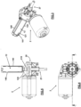
Fig.3 represents a perspective view of the gearmotor-encoder group in accordance with the present invention; -
Fig.4 represents a side view of the group shown inFig.3 ; -
Fig. 5 represents a sectional view along the line A-A ofFig.4 , -
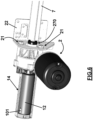
Fig.6 represents a view similar to that shown inFig.3 ; -
Fig.7 represents a further embodiment of the present invention. - For example, a control device in accordance with the present invention can be used to control a movement system of the type shown in
Fig. 1 , i.e. of the type comprising a plurality ofbelts 1 driven by anelectric gearmotor 2 as further described below and connected to a bed base 3 (a slatted base in the exemplary drawing ofFig. 1 ). A mattress can be placed on thebase 3. By means of thebelts 1, theelectric gearmotor 2 controls the raising and lowering of thebase 3. For example, one end of eachbelt 1 is constrained to a bracket 4 anchored to thebed base 3, and each belt slides on aroller 5 which, in turn, is constrained to afixed point 6. For example, thefixed points 6 are metal brackets with holes that can be used to fix them to a wall by means of screws. A second end of eachbelt 1 is constrained to ashaft 7 driven by the electric gearmotor. In practice, when theshaft 7 rotates in a first direction (for example clockwise) the belt wraps around it and thebed base 3 is raised, while when theshaft 7 rotates in the reverse direction (for example anticlockwise) the belt unwinds and thebed base 3 is lowered. In this way, theelectric gearmotor 2 determines the lifting S and the lowering A of thebed base 3. - Usually,
vertical guides 8 are provided, fixed on a wall of the vehicle in the bed installation area, which guide the vertical movement of thebed base 3. Usually,carriages 9 are mounted on one side of thebed base 3 facing theguides 8, which act as an interface element between theguides 8 and thebed base 3, facilitating and stabilising the vertical movement of the latter. - The
electric gearmotor 2 is controlled by aprogrammable encoder 10 that allows to detect the direction of rotation and the angular movements of the output shaft of the electric gearmotor itself, also acting as a position transducer and controlling the upper and lower stop points, i.e. the lifting and lowering positions of the bed. - The preceding description is provided for the purpose of contextualizing the field of application of the present invention and must therefore not be understood in a limiting sense.
- More generally, the present invention applies to bed handling systems installed in vehicles such as campers and similar so-called recreational vehicles in which a bed base is moved by an electric gearmotor controlled by an encoder.
- In accordance with the present invention, with reference to the example shown in
Figs. 1-6 , theelectric gearmotor 2 has afirst output 27 on which theshaft 7 for winding/unwinding thebelts 1 is engaged and asecond output 210 on which the rotor of theencoder 10 is engaged. In particular, thesecond output 210 consists of a power take-off. - Said
outputs output side 20 of thegearmotor 2. - The
outputs same output side 20 of thegearmotor 2. In other words, between theoutputs - Preferably, said
outputs - Preferably,
screw connections 21 are provided on theaforementioned body 20 to allow its fastening to asupport bracket 22 that, in turn, can be fastened to a wall of the vehicle in the bedinstallation area . Afurther bracket 23 acts as a support for theshaft 7 which substantially extends between thebrackets - The following description provides an example of practical implementation of a device in accordance with the present invention.
- The
rotor 100 of theencoder 10 can be connected to thesecond output 210 of thegearmotor 2 by means of a rigidtubular body 12 which, on one side, has anaxial appendage 120 configured to be inserted onto the power take-off 210 and, on the opposite side, has alateral slot 121 into which atongue 101 protruding radially from saidrotor 100 is inserted. In the accompanying exemplary drawings, theaxial appendage 120 of thetubular body 12 is formed on abase 122 of the latter turned towards thesecond output 210 of thegearmotor 2. Theradial tongue 101 and theslot 121 constitute mutually engaging parts of therotor 100 and thebody 12. In practice, therigid body 12 constitutes a direct connection element of the rotor component of theencoder 10 with thesecond output 210 of thegearmotor 2. - The
stator 102 of theencoder 10, which generally houses the electronic circuits for managing the signals produced by the rotation ofrotor component 101, is covered by a fixedtubular shell 13 which is coaxial and internal to thetubular body 12. - Preferably, a
bracket 14 can be used to fasten theencoder 10, bracket which has aplurality of arms 140 (for example, two in number) that on one side are fixed by screws to theoutput side 20 of thegearmotor 2 and on the opposite side are joined together by aring 141 fastened to an external side of the encoder stator. In the mounted device configuration, thearms 140 of thebracket 14 are external with respect to the aforementionedtubular body 12. - As highlighted in the attached exemplary drawings, the structural configuration described above allows the
encoder 10 to be arranged axially aligned with theshaft 7 for winding/unwinding thebelts 1 according to an operational arrangement that avoids the interposition of transmissions between the output of the gearmotor and the encoder and also avoids connecting theencoder 10 to theshaft 7, so that theencoder 10 is directly connected to the output of thegearmotor 2, allowing greater precision in the detection of the angular position of theshaft 7 and a more functional installation of the encoder itself. - With reference to the embodiment shown in
Fig.7 , theshaft 7 is connected to theoutput 27 of the gearmotor and the rotor of theencoder 10 is connected to theshaft 7, on the side opposite to saidoutput 27. Also in this example, the rotor of theencoder 10 is axially aligned with theoutput 27 of thegearmotor 2. However, while in the first example described above the coupling of the encoder rotor with the output of the gearmotor is direct, in the second example such coupling is indirect, in the sense that theshaft 7 is interposed between the output of the gearmotor and the rotor of the encoder. - Also in the example shown in
Fig.7 , the encoder rotor can be connected to the member that drives it into rotation (in this case the shaft 7) by means of a rigidtubular body 12 which on one side has anaxial appendage 120 configured, in this example, to be coupled axially with theshaft 7. For example, this coupling can be achieved by coupling theappendage 120 of thebody 12 with a correspondingaxial appendage 72 of theshaft 7. The arms of thebracket 14 can be fixed to thebracket 23. The other numerical references inFig.7 have the same meaning as previously described and therefore their description need not be repeated. - From the preceding description it is evident that a device in accordance with the present invention is a control device for bed handling systems installed in vehicles such as campers and similar so-called recreational vehicles comprising a
gearmotor 2 which controls the rotation of ashaft 7 on which are attachedbelts 1 to which abed base 3 is connected, wherein the rotation of theshaft 7 controlled by thegearmotor 2 in one direction or in the opposite direction causes thebed base 3 to be raised or lowered by means of thebelts 1, wherein there isanencoder 10 configured to detect one or more parameters related to the rotation of saidshaft 7, wherein said encoder has arotor 101 and astator 102, and wherein therotor 101 of the encoder is arranged coaxially with anoutput 27 of thegearmotor 2 and with saidshaft 7. - From the preceding description it is evident that a device in accordance with the present invention may have one or more of the following additional features, even combined with each other:
- the gearmotor (2) has two coaxial
synchronous outputs shaft 7 is engaged, and on the other 21) of said outputs therotor 101 of theencoder 10 is engaged. - the
rotor 101 of theencoder 10 is connected to therespective output 210 of thegearmotor 2 by means of a rigidtubular body 12. - said rigid
tubular body 12 has, on a first side, anaxial appendage 120 connected to therespective output 210 of thegearmotor 2 and, on a second side, apart 121 engaged with therotor 101 of theencoder 10. - said
part 121 of the rigidtubular body 12 consists of a lateral opening intended to engage a radial appendage of therotor 101 of theencoder 10. - the
stator 102 of theencoder 10 is fastened to thegearmotor 2 by means of abracket 14 which has a plurality ofarms 140 which, on one side, are constrained to thegearmotor 2 and, on another side, are constrained to saidstator 102, saidarms 140 being external with respect to said rigidtubular body 12. - the
stator 102 of theencoder 10 is covered by atubular shell 13 coaxial and internal to said rigidtubular body 12; - the
rotor 101 of theencoder 10 is connected to anoutput 27 of thegearmotor 2 by means of saidshaft 7. - In practice, the execution details can vary in an equivalent manner with regard to the individual elements described and illustrated, without departing from the scope of the technical solution described and therefore remaining within the limits of the protection granted by this patent in accordance with the claims that follow.
Claims (4)
- Control device for bed handling systems installed in vehicles such as campers and similar so-called recreational vehicles comprising a gearmotor (2) which controls the rotation of a shaft (7) on which are attached belts (1) to which a bed base (3) is connected, wherein the rotation of the shaft (7) controlled by the gearmotor (2) in one direction or in the opposite direction determines the lifting or lowering of the bed base (3) by means of the belts (1), and wherein there isan encoder (10) configured to detect one or more parameters related to the rotation of said shaft (7), said encoder having a rotor (101) and a stator (102), characterised in that the rotor (101) of the encoder is arranged coaxially with an output (27) of the gearmotor (2) and with said shaft (7), the gearmotor (2) has two coaxial synchronous outputs (27, 210), on one (27) of said outputs the said shaft (7) is engaged, on the other (210) of said outputs is inserted the rotor (101) of the encoder (10), the rotor (101) of the encoder (10) is connected to a respective output (210) of the gearmotor (2) by means of a rigid tubular body (12), said rigid tubular body (12) has, on a first side, an axial appendage (120) connected to the respective output (210) of the gearmotor (2) and, on a second side, a part (121) engaged with the rotor (101) of the encoder (10), and said part (121) of the rigid tubular body (12) is constituted by a lateral opening intended to engage a radial appendage of the rotor (101) of the encoder (10).
- Device according to claim 1 characterized in that the stator (102) of the encoder (10) is fixed to the gearmotor (2) by means of a bracket (14) which has several arms (140) which, on one side, are constrained to the gearmotor (2) and, on another side, are constrained to said stator (102), said arms (140) being external with respect to said rigid tubular body (12).
- Device according to any of the preceding claims characterized in that the stator (102) of the encoder (10) is covered by a tubular shell (13) coaxial and internal to said rigid tubular body (12).
- Device according to claim 1 characterized in that the rotor (101) of the encoder (10) is connected to said output (27) of the gearmotor (2) by means of said shaft (7).
Applications Claiming Priority (1)
| Application Number | Priority Date | Filing Date | Title |
|---|---|---|---|
| IT102023000022065A IT202300022065A1 (en) | 2023-10-23 | 2023-10-23 | CONTROL DEVICE FOR BED MOVEMENT SYSTEMS INSTALLED IN VEHICLES SUCH AS CAMPER CARAVANS AND THE LIKE. |
Publications (3)
| Publication Number | Publication Date |
|---|---|
| EP4545356A1 true EP4545356A1 (en) | 2025-04-30 |
| EP4545356C0 EP4545356C0 (en) | 2025-12-31 |
| EP4545356B1 EP4545356B1 (en) | 2025-12-31 |
Family
ID=90544726
Family Applications (1)
| Application Number | Title | Priority Date | Filing Date |
|---|---|---|---|
| EP24206358.4A Active EP4545356B1 (en) | 2023-10-23 | 2024-10-14 | CONTROL DEVICE FOR BED MOTION SYSTEMS |
Country Status (3)
| Country | Link |
|---|---|
| EP (1) | EP4545356B1 (en) |
| ES (1) | ES3061007T3 (en) |
| IT (1) | IT202300022065A1 (en) |
Citations (4)
| Publication number | Priority date | Publication date | Assignee | Title |
|---|---|---|---|---|
| EP1968169A2 (en) * | 2007-03-07 | 2008-09-10 | Asmo Co., Ltd. | Sensor magnet device, gear mechanism and speed reducing electric motor |
| EP3050749A1 (en) * | 2015-02-02 | 2016-08-03 | Davide Nardini | Device for handling beds |
| EP2396267B2 (en) * | 2009-02-14 | 2019-01-16 | Davide Nardini | Device for lifting bed structures |
| US11518294B1 (en) * | 2022-01-13 | 2022-12-06 | Henghong Intelligent Equipment Co., Ltd. | Electric lifting bed for automobile |
-
2023
- 2023-10-23 IT IT102023000022065A patent/IT202300022065A1/en unknown
-
2024
- 2024-10-14 EP EP24206358.4A patent/EP4545356B1/en active Active
- 2024-10-14 ES ES24206358T patent/ES3061007T3/en active Active
Patent Citations (4)
| Publication number | Priority date | Publication date | Assignee | Title |
|---|---|---|---|---|
| EP1968169A2 (en) * | 2007-03-07 | 2008-09-10 | Asmo Co., Ltd. | Sensor magnet device, gear mechanism and speed reducing electric motor |
| EP2396267B2 (en) * | 2009-02-14 | 2019-01-16 | Davide Nardini | Device for lifting bed structures |
| EP3050749A1 (en) * | 2015-02-02 | 2016-08-03 | Davide Nardini | Device for handling beds |
| US11518294B1 (en) * | 2022-01-13 | 2022-12-06 | Henghong Intelligent Equipment Co., Ltd. | Electric lifting bed for automobile |
Also Published As
| Publication number | Publication date |
|---|---|
| ES3061007T3 (en) | 2026-03-30 |
| EP4545356C0 (en) | 2025-12-31 |
| IT202300022065A1 (en) | 2025-04-23 |
| EP4545356B1 (en) | 2025-12-31 |
Similar Documents
| Publication | Publication Date | Title |
|---|---|---|
| US12567782B2 (en) | Drive motor provided with BLDC motor and swivel actuator using same | |
| CN101036579B (en) | Magnet resonance device | |
| EP3476435B1 (en) | Particle beam treatment apparatus | |
| JP2009517105A (en) | Sheet component adjusting apparatus and method, and sheet | |
| JPH0495599A (en) | Remote controller for marine propeller | |
| KR101825357B1 (en) | Hybrid Pedestal Apparatus with Automatic and Manual adjusting angle mode and Portable Satellite Communication Antenna having thesame | |
| US9791013B2 (en) | Anti-tilt feature for torsion spring for default-to-park lever | |
| WO2007140147A2 (en) | Actuator and flap arrangement with actuator interconnection | |
| EP4545356A1 (en) | Control device for bed movement systems | |
| EP2001428B1 (en) | A telescopic lifter mainly designed for height adjustment of a hospital bed | |
| EP1686418A1 (en) | In height or otherwise adjustable device for mounting of a projection device. | |
| US11396769B2 (en) | Drive assembly for a window lifter having a stop ring for a cable drum | |
| JP2013071209A (en) | Robot | |
| JP2008300608A (en) | Substrate transport apparatus having lift position confirmation means and semiconductor manufacturing apparatus having the same | |
| JP2011528760A (en) | Method of manufacturing a gate drive, gate drive system for performing the method, and use of the manufactured gate drive | |
| WO2020180223A1 (en) | Lifting device comprising a housing allowing for easy access to the interior of the lifting device | |
| US11988326B2 (en) | Low-profile modular positioning coupler | |
| US7143664B2 (en) | Electromotive servo drive | |
| JP2001078386A (en) | Linear drive | |
| EP3632835A1 (en) | Hoist cable sensor with differential drive | |
| JP2013136905A (en) | Shutter | |
| US20130313772A1 (en) | Paper out mechanism and printing apparatus with paper out mechanism | |
| JPH1034587A (en) | Industrial robot | |
| EP3050749B1 (en) | Device for handling beds | |
| KR100963625B1 (en) | Stage device with dual brake |
Legal Events
| Date | Code | Title | Description |
|---|---|---|---|
| PUAI | Public reference made under article 153(3) epc to a published international application that has entered the european phase |
Free format text: ORIGINAL CODE: 0009012 |
|
| STAA | Information on the status of an ep patent application or granted ep patent |
Free format text: STATUS: THE APPLICATION HAS BEEN PUBLISHED |
|
| AK | Designated contracting states |
Kind code of ref document: A1 Designated state(s): AL AT BE BG CH CY CZ DE DK EE ES FI FR GB GR HR HU IE IS IT LI LT LU LV MC ME MK MT NL NO PL PT RO RS SE SI SK SM TR |
|
| STAA | Information on the status of an ep patent application or granted ep patent |
Free format text: STATUS: REQUEST FOR EXAMINATION WAS MADE |
|
| 17P | Request for examination filed |
Effective date: 20250626 |
|
| GRAP | Despatch of communication of intention to grant a patent |
Free format text: ORIGINAL CODE: EPIDOSNIGR1 |
|
| STAA | Information on the status of an ep patent application or granted ep patent |
Free format text: STATUS: GRANT OF PATENT IS INTENDED |
|
| RIC1 | Information provided on ipc code assigned before grant |
Ipc: B60P 3/39 20060101AFI20250912BHEP Ipc: H02K 11/21 20160101ALI20250912BHEP Ipc: H02K 7/116 20060101ALI20250912BHEP Ipc: H02K 7/14 20060101ALI20250912BHEP |
|
| GRAS | Grant fee paid |
Free format text: ORIGINAL CODE: EPIDOSNIGR3 |
|
| INTG | Intention to grant announced |
Effective date: 20251009 |
|
| GRAA | (expected) grant |
Free format text: ORIGINAL CODE: 0009210 |
|
| STAA | Information on the status of an ep patent application or granted ep patent |
Free format text: STATUS: THE PATENT HAS BEEN GRANTED |
|
| AK | Designated contracting states |
Kind code of ref document: B1 Designated state(s): AL AT BE BG CH CY CZ DE DK EE ES FI FR GB GR HR HU IE IS IT LI LT LU LV MC ME MK MT NL NO PL PT RO RS SE SI SK SM TR |
|
| REG | Reference to a national code |
Ref country code: CH Ref legal event code: F10 Free format text: ST27 STATUS EVENT CODE: U-0-0-F10-F00 (AS PROVIDED BY THE NATIONAL OFFICE) Effective date: 20251231 Ref country code: GB Ref legal event code: FG4D |
|
| REG | Reference to a national code |
Ref country code: DE Ref legal event code: R096 Ref document number: 602024001942 Country of ref document: DE |
|
| REG | Reference to a national code |
Ref country code: IE Ref legal event code: FG4D |
|
| U01 | Request for unitary effect filed |
Effective date: 20260105 |
|
| U07 | Unitary effect registered |
Designated state(s): AT BE BG DE DK EE FI FR IT LT LU LV MT NL PT RO SE SI Effective date: 20260113 |
|
| REG | Reference to a national code |
Ref country code: ES Ref legal event code: FG2A Ref document number: 3061007 Country of ref document: ES Kind code of ref document: T3 Effective date: 20260330 |
|
| PG25 | Lapsed in a contracting state [announced via postgrant information from national office to epo] |
Ref country code: NO Free format text: LAPSE BECAUSE OF FAILURE TO SUBMIT A TRANSLATION OF THE DESCRIPTION OR TO PAY THE FEE WITHIN THE PRESCRIBED TIME-LIMIT Effective date: 20260331 |
|
| PG25 | Lapsed in a contracting state [announced via postgrant information from national office to epo] |
Ref country code: HR Free format text: LAPSE BECAUSE OF FAILURE TO SUBMIT A TRANSLATION OF THE DESCRIPTION OR TO PAY THE FEE WITHIN THE PRESCRIBED TIME-LIMIT Effective date: 20251231 |
|
| PG25 | Lapsed in a contracting state [announced via postgrant information from national office to epo] |
Ref country code: RS Free format text: LAPSE BECAUSE OF FAILURE TO SUBMIT A TRANSLATION OF THE DESCRIPTION OR TO PAY THE FEE WITHIN THE PRESCRIBED TIME-LIMIT Effective date: 20260331 |