EP4545335A1 - Display device for vehicle - Google Patents
Display device for vehicle Download PDFInfo
- Publication number
- EP4545335A1 EP4545335A1 EP22957543.6A EP22957543A EP4545335A1 EP 4545335 A1 EP4545335 A1 EP 4545335A1 EP 22957543 A EP22957543 A EP 22957543A EP 4545335 A1 EP4545335 A1 EP 4545335A1
- Authority
- EP
- European Patent Office
- Prior art keywords
- display device
- display
- display panel
- cover window
- total reflection
- Prior art date
- Legal status (The legal status is an assumption and is not a legal conclusion. Google has not performed a legal analysis and makes no representation as to the accuracy of the status listed.)
- Pending
Links
Images




Classifications
-
- B—PERFORMING OPERATIONS; TRANSPORTING
- B60—VEHICLES IN GENERAL
- B60K—ARRANGEMENT OR MOUNTING OF PROPULSION UNITS OR OF TRANSMISSIONS IN VEHICLES; ARRANGEMENT OR MOUNTING OF PLURAL DIVERSE PRIME-MOVERS IN VEHICLES; AUXILIARY DRIVES FOR VEHICLES; INSTRUMENTATION OR DASHBOARDS FOR VEHICLES; ARRANGEMENTS IN CONNECTION WITH COOLING, AIR INTAKE, GAS EXHAUST OR FUEL SUPPLY OF PROPULSION UNITS IN VEHICLES
- B60K35/00—Instruments specially adapted for vehicles; Arrangement of instruments in or on vehicles
- B60K35/20—Output arrangements, i.e. from vehicle to user, associated with vehicle functions or specially adapted therefor
- B60K35/21—Output arrangements, i.e. from vehicle to user, associated with vehicle functions or specially adapted therefor using visual output, e.g. blinking lights or matrix displays
-
- B—PERFORMING OPERATIONS; TRANSPORTING
- B60—VEHICLES IN GENERAL
- B60K—ARRANGEMENT OR MOUNTING OF PROPULSION UNITS OR OF TRANSMISSIONS IN VEHICLES; ARRANGEMENT OR MOUNTING OF PLURAL DIVERSE PRIME-MOVERS IN VEHICLES; AUXILIARY DRIVES FOR VEHICLES; INSTRUMENTATION OR DASHBOARDS FOR VEHICLES; ARRANGEMENTS IN CONNECTION WITH COOLING, AIR INTAKE, GAS EXHAUST OR FUEL SUPPLY OF PROPULSION UNITS IN VEHICLES
- B60K35/00—Instruments specially adapted for vehicles; Arrangement of instruments in or on vehicles
- B60K35/20—Output arrangements, i.e. from vehicle to user, associated with vehicle functions or specially adapted therefor
- B60K35/21—Output arrangements, i.e. from vehicle to user, associated with vehicle functions or specially adapted therefor using visual output, e.g. blinking lights or matrix displays
- B60K35/22—Display screens
-
- B—PERFORMING OPERATIONS; TRANSPORTING
- B60—VEHICLES IN GENERAL
- B60K—ARRANGEMENT OR MOUNTING OF PROPULSION UNITS OR OF TRANSMISSIONS IN VEHICLES; ARRANGEMENT OR MOUNTING OF PLURAL DIVERSE PRIME-MOVERS IN VEHICLES; AUXILIARY DRIVES FOR VEHICLES; INSTRUMENTATION OR DASHBOARDS FOR VEHICLES; ARRANGEMENTS IN CONNECTION WITH COOLING, AIR INTAKE, GAS EXHAUST OR FUEL SUPPLY OF PROPULSION UNITS IN VEHICLES
- B60K35/00—Instruments specially adapted for vehicles; Arrangement of instruments in or on vehicles
- B60K35/20—Output arrangements, i.e. from vehicle to user, associated with vehicle functions or specially adapted therefor
- B60K35/21—Output arrangements, i.e. from vehicle to user, associated with vehicle functions or specially adapted therefor using visual output, e.g. blinking lights or matrix displays
- B60K35/22—Display screens
- B60K35/223—Flexible displays
-
- B—PERFORMING OPERATIONS; TRANSPORTING
- B60—VEHICLES IN GENERAL
- B60K—ARRANGEMENT OR MOUNTING OF PROPULSION UNITS OR OF TRANSMISSIONS IN VEHICLES; ARRANGEMENT OR MOUNTING OF PLURAL DIVERSE PRIME-MOVERS IN VEHICLES; AUXILIARY DRIVES FOR VEHICLES; INSTRUMENTATION OR DASHBOARDS FOR VEHICLES; ARRANGEMENTS IN CONNECTION WITH COOLING, AIR INTAKE, GAS EXHAUST OR FUEL SUPPLY OF PROPULSION UNITS IN VEHICLES
- B60K35/00—Instruments specially adapted for vehicles; Arrangement of instruments in or on vehicles
- B60K35/20—Output arrangements, i.e. from vehicle to user, associated with vehicle functions or specially adapted therefor
- B60K35/21—Output arrangements, i.e. from vehicle to user, associated with vehicle functions or specially adapted therefor using visual output, e.g. blinking lights or matrix displays
- B60K35/23—Head-up displays [HUD]
-
- B—PERFORMING OPERATIONS; TRANSPORTING
- B60—VEHICLES IN GENERAL
- B60K—ARRANGEMENT OR MOUNTING OF PROPULSION UNITS OR OF TRANSMISSIONS IN VEHICLES; ARRANGEMENT OR MOUNTING OF PLURAL DIVERSE PRIME-MOVERS IN VEHICLES; AUXILIARY DRIVES FOR VEHICLES; INSTRUMENTATION OR DASHBOARDS FOR VEHICLES; ARRANGEMENTS IN CONNECTION WITH COOLING, AIR INTAKE, GAS EXHAUST OR FUEL SUPPLY OF PROPULSION UNITS IN VEHICLES
- B60K35/00—Instruments specially adapted for vehicles; Arrangement of instruments in or on vehicles
- B60K35/20—Output arrangements, i.e. from vehicle to user, associated with vehicle functions or specially adapted therefor
- B60K35/21—Output arrangements, i.e. from vehicle to user, associated with vehicle functions or specially adapted therefor using visual output, e.g. blinking lights or matrix displays
- B60K35/23—Head-up displays [HUD]
- B60K35/231—Head-up displays [HUD] characterised by their arrangement or structure for integration into vehicles
-
- B—PERFORMING OPERATIONS; TRANSPORTING
- B60—VEHICLES IN GENERAL
- B60K—ARRANGEMENT OR MOUNTING OF PROPULSION UNITS OR OF TRANSMISSIONS IN VEHICLES; ARRANGEMENT OR MOUNTING OF PLURAL DIVERSE PRIME-MOVERS IN VEHICLES; AUXILIARY DRIVES FOR VEHICLES; INSTRUMENTATION OR DASHBOARDS FOR VEHICLES; ARRANGEMENTS IN CONNECTION WITH COOLING, AIR INTAKE, GAS EXHAUST OR FUEL SUPPLY OF PROPULSION UNITS IN VEHICLES
- B60K35/00—Instruments specially adapted for vehicles; Arrangement of instruments in or on vehicles
- B60K35/50—Instruments characterised by their means of attachment to or integration in the vehicle
- B60K35/53—Movable instruments, e.g. slidable
-
- B—PERFORMING OPERATIONS; TRANSPORTING
- B60—VEHICLES IN GENERAL
- B60K—ARRANGEMENT OR MOUNTING OF PROPULSION UNITS OR OF TRANSMISSIONS IN VEHICLES; ARRANGEMENT OR MOUNTING OF PLURAL DIVERSE PRIME-MOVERS IN VEHICLES; AUXILIARY DRIVES FOR VEHICLES; INSTRUMENTATION OR DASHBOARDS FOR VEHICLES; ARRANGEMENTS IN CONNECTION WITH COOLING, AIR INTAKE, GAS EXHAUST OR FUEL SUPPLY OF PROPULSION UNITS IN VEHICLES
- B60K35/00—Instruments specially adapted for vehicles; Arrangement of instruments in or on vehicles
- B60K35/55—Instruments with parts that can change their shape or position to configure an active screen, e.g. by folding or by rolling
-
- B—PERFORMING OPERATIONS; TRANSPORTING
- B60—VEHICLES IN GENERAL
- B60R—VEHICLES, VEHICLE FITTINGS, OR VEHICLE PARTS, NOT OTHERWISE PROVIDED FOR
- B60R11/00—Arrangements for holding or mounting articles, not otherwise provided for
- B60R11/02—Arrangements for holding or mounting articles, not otherwise provided for for radio sets, television sets, telephones, or the like; Arrangement of controls thereof
-
- G—PHYSICS
- G02—OPTICS
- G02B—OPTICAL ELEMENTS, SYSTEMS OR APPARATUS
- G02B27/00—Optical systems or apparatus not provided for by any of the groups G02B1/00 - G02B26/00, G02B30/00
- G02B27/01—Head-up displays
- G02B27/0101—Head-up displays characterised by optical features
-
- G—PHYSICS
- G02—OPTICS
- G02B—OPTICAL ELEMENTS, SYSTEMS OR APPARATUS
- G02B27/00—Optical systems or apparatus not provided for by any of the groups G02B1/00 - G02B26/00, G02B30/00
- G02B27/01—Head-up displays
- G02B27/0149—Head-up displays characterised by mechanical features
-
- G—PHYSICS
- G02—OPTICS
- G02B—OPTICAL ELEMENTS, SYSTEMS OR APPARATUS
- G02B27/00—Optical systems or apparatus not provided for by any of the groups G02B1/00 - G02B26/00, G02B30/00
- G02B27/01—Head-up displays
- G02B27/0179—Display position adjusting means not related to the information to be displayed
-
- G—PHYSICS
- G02—OPTICS
- G02B—OPTICAL ELEMENTS, SYSTEMS OR APPARATUS
- G02B5/00—Optical elements other than lenses
- G02B5/04—Prisms
-
- G—PHYSICS
- G03—PHOTOGRAPHY; CINEMATOGRAPHY; ANALOGOUS TECHNIQUES USING WAVES OTHER THAN OPTICAL WAVES; ELECTROGRAPHY; HOLOGRAPHY
- G03B—APPARATUS OR ARRANGEMENTS FOR TAKING PHOTOGRAPHS OR FOR PROJECTING OR VIEWING THEM; APPARATUS OR ARRANGEMENTS EMPLOYING ANALOGOUS TECHNIQUES USING WAVES OTHER THAN OPTICAL WAVES; ACCESSORIES THEREFOR
- G03B21/00—Projectors or projection-type viewers; Accessories therefor
- G03B21/14—Details
- G03B21/28—Reflectors in projection beam
-
- B—PERFORMING OPERATIONS; TRANSPORTING
- B60—VEHICLES IN GENERAL
- B60K—ARRANGEMENT OR MOUNTING OF PROPULSION UNITS OR OF TRANSMISSIONS IN VEHICLES; ARRANGEMENT OR MOUNTING OF PLURAL DIVERSE PRIME-MOVERS IN VEHICLES; AUXILIARY DRIVES FOR VEHICLES; INSTRUMENTATION OR DASHBOARDS FOR VEHICLES; ARRANGEMENTS IN CONNECTION WITH COOLING, AIR INTAKE, GAS EXHAUST OR FUEL SUPPLY OF PROPULSION UNITS IN VEHICLES
- B60K2360/00—Indexing scheme associated with groups B60K35/00 or B60K37/00 relating to details of instruments or dashboards
- B60K2360/1526—Dual-view displays
-
- B—PERFORMING OPERATIONS; TRANSPORTING
- B60—VEHICLES IN GENERAL
- B60K—ARRANGEMENT OR MOUNTING OF PROPULSION UNITS OR OF TRANSMISSIONS IN VEHICLES; ARRANGEMENT OR MOUNTING OF PLURAL DIVERSE PRIME-MOVERS IN VEHICLES; AUXILIARY DRIVES FOR VEHICLES; INSTRUMENTATION OR DASHBOARDS FOR VEHICLES; ARRANGEMENTS IN CONNECTION WITH COOLING, AIR INTAKE, GAS EXHAUST OR FUEL SUPPLY OF PROPULSION UNITS IN VEHICLES
- B60K2360/00—Indexing scheme associated with groups B60K35/00 or B60K37/00 relating to details of instruments or dashboards
- B60K2360/16—Type of output information
- B60K2360/166—Navigation
-
- B—PERFORMING OPERATIONS; TRANSPORTING
- B60—VEHICLES IN GENERAL
- B60K—ARRANGEMENT OR MOUNTING OF PROPULSION UNITS OR OF TRANSMISSIONS IN VEHICLES; ARRANGEMENT OR MOUNTING OF PLURAL DIVERSE PRIME-MOVERS IN VEHICLES; AUXILIARY DRIVES FOR VEHICLES; INSTRUMENTATION OR DASHBOARDS FOR VEHICLES; ARRANGEMENTS IN CONNECTION WITH COOLING, AIR INTAKE, GAS EXHAUST OR FUEL SUPPLY OF PROPULSION UNITS IN VEHICLES
- B60K2360/00—Indexing scheme associated with groups B60K35/00 or B60K37/00 relating to details of instruments or dashboards
- B60K2360/18—Information management
- B60K2360/186—Displaying information according to relevancy
- B60K2360/1868—Displaying information according to relevancy according to driving situations
-
- B—PERFORMING OPERATIONS; TRANSPORTING
- B60—VEHICLES IN GENERAL
- B60K—ARRANGEMENT OR MOUNTING OF PROPULSION UNITS OR OF TRANSMISSIONS IN VEHICLES; ARRANGEMENT OR MOUNTING OF PLURAL DIVERSE PRIME-MOVERS IN VEHICLES; AUXILIARY DRIVES FOR VEHICLES; INSTRUMENTATION OR DASHBOARDS FOR VEHICLES; ARRANGEMENTS IN CONNECTION WITH COOLING, AIR INTAKE, GAS EXHAUST OR FUEL SUPPLY OF PROPULSION UNITS IN VEHICLES
- B60K2360/00—Indexing scheme associated with groups B60K35/00 or B60K37/00 relating to details of instruments or dashboards
- B60K2360/18—Information management
- B60K2360/186—Displaying information according to relevancy
- B60K2360/1876—Displaying information according to relevancy according to vehicle situations
-
- B—PERFORMING OPERATIONS; TRANSPORTING
- B60—VEHICLES IN GENERAL
- B60K—ARRANGEMENT OR MOUNTING OF PROPULSION UNITS OR OF TRANSMISSIONS IN VEHICLES; ARRANGEMENT OR MOUNTING OF PLURAL DIVERSE PRIME-MOVERS IN VEHICLES; AUXILIARY DRIVES FOR VEHICLES; INSTRUMENTATION OR DASHBOARDS FOR VEHICLES; ARRANGEMENTS IN CONNECTION WITH COOLING, AIR INTAKE, GAS EXHAUST OR FUEL SUPPLY OF PROPULSION UNITS IN VEHICLES
- B60K2360/00—Indexing scheme associated with groups B60K35/00 or B60K37/00 relating to details of instruments or dashboards
- B60K2360/18—Information management
- B60K2360/195—Blocking or enabling display functions
-
- B—PERFORMING OPERATIONS; TRANSPORTING
- B60—VEHICLES IN GENERAL
- B60K—ARRANGEMENT OR MOUNTING OF PROPULSION UNITS OR OF TRANSMISSIONS IN VEHICLES; ARRANGEMENT OR MOUNTING OF PLURAL DIVERSE PRIME-MOVERS IN VEHICLES; AUXILIARY DRIVES FOR VEHICLES; INSTRUMENTATION OR DASHBOARDS FOR VEHICLES; ARRANGEMENTS IN CONNECTION WITH COOLING, AIR INTAKE, GAS EXHAUST OR FUEL SUPPLY OF PROPULSION UNITS IN VEHICLES
- B60K2360/00—Indexing scheme associated with groups B60K35/00 or B60K37/00 relating to details of instruments or dashboards
- B60K2360/20—Optical features of instruments
- B60K2360/23—Optical features of instruments using reflectors
-
- B—PERFORMING OPERATIONS; TRANSPORTING
- B60—VEHICLES IN GENERAL
- B60K—ARRANGEMENT OR MOUNTING OF PROPULSION UNITS OR OF TRANSMISSIONS IN VEHICLES; ARRANGEMENT OR MOUNTING OF PLURAL DIVERSE PRIME-MOVERS IN VEHICLES; AUXILIARY DRIVES FOR VEHICLES; INSTRUMENTATION OR DASHBOARDS FOR VEHICLES; ARRANGEMENTS IN CONNECTION WITH COOLING, AIR INTAKE, GAS EXHAUST OR FUEL SUPPLY OF PROPULSION UNITS IN VEHICLES
- B60K2360/00—Indexing scheme associated with groups B60K35/00 or B60K37/00 relating to details of instruments or dashboards
- B60K2360/20—Optical features of instruments
- B60K2360/27—Optical features of instruments using semi-transparent optical elements
-
- B—PERFORMING OPERATIONS; TRANSPORTING
- B60—VEHICLES IN GENERAL
- B60K—ARRANGEMENT OR MOUNTING OF PROPULSION UNITS OR OF TRANSMISSIONS IN VEHICLES; ARRANGEMENT OR MOUNTING OF PLURAL DIVERSE PRIME-MOVERS IN VEHICLES; AUXILIARY DRIVES FOR VEHICLES; INSTRUMENTATION OR DASHBOARDS FOR VEHICLES; ARRANGEMENTS IN CONNECTION WITH COOLING, AIR INTAKE, GAS EXHAUST OR FUEL SUPPLY OF PROPULSION UNITS IN VEHICLES
- B60K2360/00—Indexing scheme associated with groups B60K35/00 or B60K37/00 relating to details of instruments or dashboards
- B60K2360/20—Optical features of instruments
- B60K2360/33—Illumination features
- B60K2360/334—Projection means
-
- B—PERFORMING OPERATIONS; TRANSPORTING
- B60—VEHICLES IN GENERAL
- B60K—ARRANGEMENT OR MOUNTING OF PROPULSION UNITS OR OF TRANSMISSIONS IN VEHICLES; ARRANGEMENT OR MOUNTING OF PLURAL DIVERSE PRIME-MOVERS IN VEHICLES; AUXILIARY DRIVES FOR VEHICLES; INSTRUMENTATION OR DASHBOARDS FOR VEHICLES; ARRANGEMENTS IN CONNECTION WITH COOLING, AIR INTAKE, GAS EXHAUST OR FUEL SUPPLY OF PROPULSION UNITS IN VEHICLES
- B60K2360/00—Indexing scheme associated with groups B60K35/00 or B60K37/00 relating to details of instruments or dashboards
- B60K2360/20—Optical features of instruments
- B60K2360/33—Illumination features
- B60K2360/343—Illumination of matrix displays
- B60K2360/344—Illumination of matrix displays for additionally illuminating mechanical elements, e.g. pointers or control knobs
-
- B—PERFORMING OPERATIONS; TRANSPORTING
- B60—VEHICLES IN GENERAL
- B60K—ARRANGEMENT OR MOUNTING OF PROPULSION UNITS OR OF TRANSMISSIONS IN VEHICLES; ARRANGEMENT OR MOUNTING OF PLURAL DIVERSE PRIME-MOVERS IN VEHICLES; AUXILIARY DRIVES FOR VEHICLES; INSTRUMENTATION OR DASHBOARDS FOR VEHICLES; ARRANGEMENTS IN CONNECTION WITH COOLING, AIR INTAKE, GAS EXHAUST OR FUEL SUPPLY OF PROPULSION UNITS IN VEHICLES
- B60K2360/00—Indexing scheme associated with groups B60K35/00 or B60K37/00 relating to details of instruments or dashboards
- B60K2360/60—Structural details of dashboards or instruments
- B60K2360/66—Projection screens or combiners
-
- B—PERFORMING OPERATIONS; TRANSPORTING
- B60—VEHICLES IN GENERAL
- B60K—ARRANGEMENT OR MOUNTING OF PROPULSION UNITS OR OF TRANSMISSIONS IN VEHICLES; ARRANGEMENT OR MOUNTING OF PLURAL DIVERSE PRIME-MOVERS IN VEHICLES; AUXILIARY DRIVES FOR VEHICLES; INSTRUMENTATION OR DASHBOARDS FOR VEHICLES; ARRANGEMENTS IN CONNECTION WITH COOLING, AIR INTAKE, GAS EXHAUST OR FUEL SUPPLY OF PROPULSION UNITS IN VEHICLES
- B60K35/00—Instruments specially adapted for vehicles; Arrangement of instruments in or on vehicles
- B60K35/60—Instruments characterised by their location or relative disposition in or on vehicles
-
- B—PERFORMING OPERATIONS; TRANSPORTING
- B60—VEHICLES IN GENERAL
- B60R—VEHICLES, VEHICLE FITTINGS, OR VEHICLE PARTS, NOT OTHERWISE PROVIDED FOR
- B60R11/00—Arrangements for holding or mounting articles, not otherwise provided for
- B60R2011/0001—Arrangements for holding or mounting articles, not otherwise provided for characterised by position
- B60R2011/0003—Arrangements for holding or mounting articles, not otherwise provided for characterised by position inside the vehicle
- B60R2011/0005—Dashboard
-
- B—PERFORMING OPERATIONS; TRANSPORTING
- B60—VEHICLES IN GENERAL
- B60R—VEHICLES, VEHICLE FITTINGS, OR VEHICLE PARTS, NOT OTHERWISE PROVIDED FOR
- B60R11/00—Arrangements for holding or mounting articles, not otherwise provided for
- B60R2011/0042—Arrangements for holding or mounting articles, not otherwise provided for characterised by mounting means
- B60R2011/008—Adjustable or movable supports
- B60R2011/0085—Adjustable or movable supports with adjustment by rotation in their operational position
-
- B—PERFORMING OPERATIONS; TRANSPORTING
- B60—VEHICLES IN GENERAL
- B60R—VEHICLES, VEHICLE FITTINGS, OR VEHICLE PARTS, NOT OTHERWISE PROVIDED FOR
- B60R11/00—Arrangements for holding or mounting articles, not otherwise provided for
- B60R2011/0042—Arrangements for holding or mounting articles, not otherwise provided for characterised by mounting means
- B60R2011/008—Adjustable or movable supports
- B60R2011/0092—Adjustable or movable supports with motorization
-
- G—PHYSICS
- G02—OPTICS
- G02B—OPTICAL ELEMENTS, SYSTEMS OR APPARATUS
- G02B27/00—Optical systems or apparatus not provided for by any of the groups G02B1/00 - G02B26/00, G02B30/00
- G02B27/01—Head-up displays
- G02B27/0101—Head-up displays characterised by optical features
- G02B2027/013—Head-up displays characterised by optical features comprising a combiner of particular shape, e.g. curvature
-
- G—PHYSICS
- G02—OPTICS
- G02B—OPTICAL ELEMENTS, SYSTEMS OR APPARATUS
- G02B27/00—Optical systems or apparatus not provided for by any of the groups G02B1/00 - G02B26/00, G02B30/00
- G02B27/01—Head-up displays
- G02B27/0149—Head-up displays characterised by mechanical features
- G02B2027/0154—Head-up displays characterised by mechanical features with movable elements
-
- G—PHYSICS
- G02—OPTICS
- G02B—OPTICAL ELEMENTS, SYSTEMS OR APPARATUS
- G02B27/00—Optical systems or apparatus not provided for by any of the groups G02B1/00 - G02B26/00, G02B30/00
- G02B27/01—Head-up displays
- G02B27/0149—Head-up displays characterised by mechanical features
- G02B2027/0161—Head-up displays characterised by mechanical features characterised by the relative positioning of the constitutive elements
-
- G—PHYSICS
- G02—OPTICS
- G02B—OPTICAL ELEMENTS, SYSTEMS OR APPARATUS
- G02B27/00—Optical systems or apparatus not provided for by any of the groups G02B1/00 - G02B26/00, G02B30/00
- G02B27/01—Head-up displays
- G02B27/0149—Head-up displays characterised by mechanical features
- G02B2027/0165—Head-up displays characterised by mechanical features associated with a head-down display
Definitions
- the present invention relates to a display device for a vehicle.
- An example of a display device for a vehicle includes a video device for a vehicle that is disclosed in Korean Patent Publication No. 10-2018-0004633 A (published on January 12, 2018 ), which includes a display that displays an image using data received wiredly or wirelessly from a mobile terminal or a micro controller unit (MCU) of the vehicle; a transparent prism which is seated on one surface of the display and transmits or reflects an image emitted from the display; and a casing on which the display and the transparent prism are seated.
- MCU micro controller unit
- the present embodiment provides a display device for a vehicle, which is capable of providing two displays with a simple structure.
- a display device for a vehicle may include a display module provided with a display panel and a cover window disposed on one surface of the display panel, and a drive mechanism configured to lay down the display module or stand up the display module.
- the cover window may include a total reflection area on which an image emitted from the display panel is totally reflected, and a transmission area on which the image emitted from the display panel is transmitted.
- a surface area of the total reflection area may be less than that of the transmission area.
- the drive mechanism may be performed in a plurality of modes.
- the plurality of modes may include a first mode in which an emission surface of the total reflection area faces backward, and a second mode in which an emission surface of the transmission area faces backward.
- the emission surface of the transmission area may face upward.
- the emission surface of the total reflection area may face downward.
- the cover window may include: a flat plate portion comprising the transmission area; and a prism portion disposed on one end of the flat plate portion and comprising the total reflection area.
- the display module may further include a cover decoration disposed on the cover window.
- the drive mechanism may be connected to the cover decoration.
- An example of the drive mechanism may include a rotary motor configured to rotate the cover decoration.
- Another example of the drive mechanism may include: a rotary motor connected to a rotation shaft disposed on the cover decoration; a bearing through which the rotation shaft passes; a pinion to which an outer circumference of the bearing is fixed; a rack with which the pinion is engaged; a moving drive gear engaged with the pinion; and a moving motor connected to the moving drive gear.
- the moving drive gear may be spaced apart from the rack in a vertical direction.
- the cover window may include: a flat plate portion; a prism portion that is thicker than the flat plate portion; and a connection body configured to connect the flat plate portion to the prism portion.
- connection body may include a multi-link in which a plurality of unit links are sequentially connected in a row.
- the display panel may include a flexible display panel.
- the display panel may include: a first panel facing the total reflection area; and a second panel facing the transmission area.
- the convenience may be improved by providing the two screens having the different sizes with one display device for the vehicle.
- the display device for the vehicle may display the small screen having the small size, and when the vehicle is stopped or driving autonomously, the display device for the vehicle may display the main screen having the large size, and thus, the frequency of use and the utilization of the display device for the vehicle may be high.
- the small screen having the small size and the large screen that is visible through the windshield may be provided through one display device to improve the utilization and minimize the number of display devices installed in the vehicle.
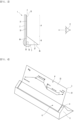
- FIG. 1 is a side view when an example of a display device for a vehicle is a small display according to the present embodiment
- FIG. 2 is a perspective view when the example of the display device for the vehicle is the small display according to the present embodiment
- FIG. 3 is a side view when an example of the display device for the vehicle is a main display according to the present embodiment
- FIG. 4 is a perspective view when the example of the display device for the vehicle is the main display according to the present embodiment
- FIG. 5 is a perspective view illustrating an example of a cover window according to the present embodiment.
- An example of a display device for a vehicle may include a display module 1.
- the display module 1 may include a display panel 2 and a cover window 3.
- the display panel 2 may be a liquid crystal display (LCD) or an organic light emitting diode (OLED).
- LCD liquid crystal display
- OLED organic light emitting diode
- the type of display panel 2 is not limited, and various types may be applied.
- the cover window 3 may be disposed on one surface of the display panel 2.
- the cover window 3 may be disposed on a top surface of the display panel 2.
- the cover window 3 may be disposed on a rear surface of the display panel 2.
- the cover window 3 may include a total reflection area R and a transmission area P.
- the cover window 3 may lay down or stand up together with the display panel 2.
- the total reflection area R may be an area on which an image emitted from the display panel 2 is totally reflected when the cover window 3 lays down, as illustrated in FIGS. 1 and 2 .
- the transmission area P may be an area through which the image emitted from the display panel 2 is transmitted when the cover window 3 stands up, as illustrated in FIGS. 3 and 4 .
- the total reflection area R may be disposed in a row in a forward and backward direction X.
- the transmission area P may be disposed in front of the total reflection area R, and the total reflection area R may be disposed behind the transmission area P, as illustrated in FIG. 1 .
- the total reflection area R may be disposed in a row in a vertical direction Z.
- the transmission area P may be disposed above the total reflection area R, and the total reflection area R may be disposed below the transmission area P, as illustrated in FIG. 3 .
- the image emitted from the display panel 2 may be totally reflected backward by the total reflection area R.
- the total reflection area R may provide a screen to a driver E (eye box) riding in the vehicle.
- the image emitted from the display panel 2 may be emitted backward through the transmission area P.
- the transmission area P may provide a screen to the driver E (eye box) riding in the vehicle.
- a surface area of the total reflection area R may be less than that of the transmission area P.
- the display module 1 may provide a small display or server screen, which has a small size and has a total reflection area R facing backward when the cover window 3 lays down as illustrated in FIGS. 1 and 2 .
- the display module 1 may have a main display or large screen, which has a large size and has a transmission area P facing backward when the cover window 3 lays down as illustrated in FIGS. 3 and 4 .
- the cover window 3 may include a flat plate portion 31 and a prism portion 34.
- the flat plate portion 31 may include a transmission area P.
- the flat plate portion 31 may have a front surface as an incident surface 32 and a rear surface as an emission surface 33 when the cover window 3 stands up.
- the flat plate portion 31 may emit the image incident from the front to the rear when the cover window 3 stands up.
- the prism portion 34 may be disposed on one end of the flat plate portion 31.
- the prism portion 34 may be disposed on a rear end of the flat plate portion 31 when the cover window 3 lays down.
- the prism portion 34 may be disposed on a lower end of the flat plate portion 31 when the cover window stands up.
- the prism portion 34 may include a total reflection area R.
- the prism portion 34 may have a bottom surface as an incident surface 35, and a rear surface an emission surface 36 when the cover window 3 lays down.
- the prism portion 34 may include an inclined surface when the cover window 3 lays down and may be a total reflection surface 37 that totally reflects the image backward.
- the prism portion 34 may reflect the image, which is incident from the lower side, backward from the total reflection surface 37when the cover window 3 lays down and may reflect the image, which is reflected from the total reflection surface 37, backward.
- a material of the cover window 3 having the prism portion 34 may be a transparent ceramic series (glass, quartz, etc.) or a transparent polymer series (acrylic, PS, epoxy, PC, etc.).
- the prism portion 34 may not undergo any separate surface treatment applied to the total reflection surface 37 and may also undergo surface treatment applied to the total reflection surface 37 such as deposition or printing to improve brightness, etc.
- the display module 1 may further include a cover decoration 4 as illustrated in FIGS. 3 and 4 .
- the cover decoration 4 may be disposed on the cover window 3.
- the cover decoration 4 may surround an edge of the cover window 3.
- the cover decoration 4 may be coupled to at least one of the display panel 2 or the cover window 3, and may be integrated with the display panel 2 and the cover window 3.
- the display panel 2 and the cover window 3 may be coupled by the cover window 3.
- the cover decoration 4 may surround both left and right ends of the flat plate 31.
- the cover decoration 4 may surround both left and right ends of the prism portion 34.
- An example of the display device for the vehicle may further include a display module 1, particularly a drive mechanism 5 that lays down or stand up the display panel 2 and window 3.
- a first position at which the display module 1 lays down may be defined as a position at which the display module 1 is disposed horizontally or a position at which the display module 1 is disposed to be inclined close to a horizontal plane.
- a second position at which the display module 1 stands up may be defined as a position where the display module 1 is disposed vertically or a position at which the display module 1 is disposed to be inclined close to the vertical plane.
- An example of a drive mechanism 5 may be a rotary mechanism that rotates the display module 1 around a rotation shaft 42.
- the drive mechanism 5 may be connected to the cover decoration 4 and may rotate the cover decoration 4, and the display panel 2 and the cover window 3 may rotate together with the cover decoration 4.
- An example of the drive mechanism 5 may be a rotary motor that rotates the cover decoration 4.
- the rotation shaft 42 may be disposed at one of left and right sides of the cover decoration 4.
- the rotation shaft 42 may be disposed to protrude from a side surface of the cover decoration 4.
- the rotary motor which is the drive mechanism 5, may be disposed next to the cover decoration 4 and connected to a rotation shaft 42 to rotate the cover decoration 4.
- An example of the display device for the vehicle may further include a mounter 6 mounted on the vehicle.
- the rotary motor may be disposed on the mounter 6 and supported by the mounter 6.
- the drive mechanism 5 may perform a plurality of modes.
- the plurality of modes may include a first mode and a second mode.
- the first mode may be a mode in which the display panel 2 and the cover window 3 lay down as illustrated in FIGS. 1 and 2 .
- the first mode may be a mode in which the emission surface 36 of the total reflection area R faces backward.
- the first mode may be a mode in which the emission surface 33 of the transmission area R faces upward.
- the display panel 2 may emit image light onto the total reflection area R, and the image light emitted from the display panel 2 may be totally reflected by the total reflection surface 37 and then emitted backward.
- the second mode may be a mode in which the display panel 2 and the cover window 3 stand up as illustrated in FIGS. 3 and 4 .
- the second mode may be a mode in which the emission surface of the transmission area R faces backward.
- the second mode may be a mode in which the emission surface of the total reflection area R faces downward.
- the display panel 2 may emit image light onto the transmission area P, and the image light emitted from the display panel 2 may be transmitted through the emission surface 33 and then emitted backward.
- An example of the display device for the vehicle may further include a controller that controls the rotary motor.
- the controller may control the display panel 2 and the drive mechanism 5 in different modes depending on the vehicle's driving mode (stop, low-speed driving, high-speed driving, etc.).
- the display panel 2 may display vehicle driving information such as P (parking), R (reverse), N (neutral), and D (drive).
- vehicle driving information such as P (parking), R (reverse), N (neutral), and D (drive).
- the display panel 2 may display schedule information such as reservation information.
- the display panel 2 may display vehicle's speed information in numerical form, etc.
- the display panel 2 may include direction information such as left turn, right turn, and straight ahead, as well as distance information.
- the display panel 2 may display map information such as a vehicle's final destination or an altitude change to a final destination.
- the display panel 2 may display vehicle driving information, schedule information, vehicle speed information, direction information, distance information, etc., and image light including vehicle driving information, schedule information, vehicle speed information, direction information, distance information, etc. may be directed backward through the total reflection area R when the cover window 3 lays down, as illustrated in FIG. 2 .
- the display panel 2 may display map information, etc., and image light including map information, etc. may be directed backward through the transmission area P while the cover window 3 stands up, as illustrated in FIG. 4 .
- FIG. 6 is an enlarged cross-sectional view illustrating various examples of the cover window according to the present embodiment.
- a flat plate portion 31 and a prism portion 34 may be integrated with each other, and the prism portion 34 may be thicker than the flat plate portion 31.
- cover window 3 may include, as illustrated (b) of FIG. 6 , a flat plate portion 31', a prism portion 34', and a connection body 38, and the prism portion 34' may be thicker than the flat plate portion 31'.
- connection body 38 may connect the flat plate portion 31' to the prism portion 34'.
- the flat plate portion 31' and the prism portion 34' may be manufactured separately and connected by the connection body 38.
- connection body 38 may be connected to one end of the flat plate portion 31' and may cover one surface of the prism portion 34'.
- connection body 38 may include a boundary part 38A disposed between the flat plate portion 31' and the prism portion 34', and a cover portion 38B extending from the boundary part 38A to cover one surface of the prism portion 34'.
- An incident surface 35 of the prism portion 34" may be attached to one surface of the flat plate portion 31" by an adhesive means such as a transparent adhesive.
- the flat plate portion 31" may include an overlapping area O and a non-overlapping area NO.
- the overlapping area O may be disposed between the display panel 2 and the prism portion 34" and may be an area overlapping each of the display panel 2 and the prism portion 34".
- the non-overlapping area NO may be an area that overlaps the display panel 2 and does not overlap the prism portion 34".
- FIG. 7 is a cross-sectional view illustrating various examples of the prism portion according to the present embodiment.
- An example of the prism portion 34 may be configured as a right-angle prism that internally totally reflects image light at a right angle, as illustrated in (a) of FIG. 7 .
- prism portion 34 may be configured as a penta prism that internally totally reflects image light plurality of times, as illustrated in (b) of FIG. 7 .
- prism portion 34 may be a dove prism used to invert the top and bottom of an image, as illustrated in (c) of FIG. 7 .
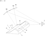
- FIG. 8 is a side view illustrating a modified example of the example of the display device for the vehicle according to the present embodiment.
- FIG. 9 is a perspective view of the modified example of the example of the display device for the vehicle according to the present embodiment.
- the display panel 2 when the cover window 3 lays down, the display panel 2 may display information, and the display panel 2 may emit image light to the flat plate portion 31 and the prism portion 34.
- the image light emitted from the flat plate portion 31 may be directed upward after passing through the flat plate portion 31 and may be directed toward a windshield WS of the vehicle.
- the display panel 2 may be used as a light source for a head-up display HUD, and a user E may recognize a virtual image formed in front of the windshield WS and a screen of the main display.
- the image light emitted from the prism portion 34 may be emitted backward after being totally reflected by the prism portion 34, and the user E may recognize the screen of the small display expressed through the prism portion 34.
- the display panel 2 may emit image light onto the total reflection area R and the transmission area P, and the image light emitted from the display panel 2 onto the total reflection area R may be totally reflected from the total reflection surface 37 and then emitted backward, and also, the image light emitted from the display panel 2 onto the transmission area P may be directed toward the wind shield WS after being transmitted through the transmission area 33.
- the modified example of the example of the display device for the vehicle may be the same as or similar to the example of the display device for the vehicle in terms of its configuration and operation, except that the display panel 2 emits image light onto the total reflection area R and the transmission area P in the first mode of the drive mechanism 5, and thus, the same symbols are used, and detailed descriptions thereof will be omitted.
- FIG. 10 is a side view illustrating an example in which a display module of another example of the display device for the vehicle slidably moves and rotates according to the present embodiment
- FIG. 11 is a perspective view of a drive mechanism as another example of the display device for the vehicle according to the present embodiment
- FIG. 12 is a control block diagram illustrating another example of the display device for the vehicle according to the present embodiment.
- Another example of a drive mechanism 5' may rotate the display module 1 as well as move the display module 1 linearly.
- the drive mechanism 5' may slide the display module 1 in a forward and backward direction X after rotating the display module 1, may slide the display module 1 in the forward and backward direction X to rotate the display module 1, and may rotate the display module 1 to slide the display module 1 in the forward and backward direction X.
- the drive mechanism 5' may be a rotary mechanism 52 connected to a rotation shaft 42 disposed on a cover decoration 4.
- An example of the rotary mechanism 52 may be a rotary motor 52 connected to the rotation shaft 42, and thus, the rotary mechanism 52 and the rotary motor 52 may be described by using the same symbol.
- the rotary motor 52 may be connected to the rotation shaft 42 to rotate the rotation shaft 42.
- the display module 1 may be rotated around the rotation shaft 42.
- the drive mechanism 5' may include a moving mechanism that moves the rotation shaft 42 linearly.
- An example of the moving mechanism may include a bearing 53 through which the rotation shaft 42 passes, a pinion 55 to which an outer circumference of the bearing 53 is fixed, a moving drive gear 56 engaged with the pinion 55, a moving motor 57 connected to the moving drive gear 56, and a rack 58 engaged with the pinion 55.
- An example of the bearing 53 may be a ball bearing, and the bearing 53 may include an inner ring, an outer ring, and a plurality of balls disposed between the inner ring and the outer ring.
- An inner circumference of the inner ring may be an inner circumference of the bearing 53
- an outer circumference of the outer ring may be an outer circumference of the bearing 53.
- the rotation shaft 42 may pass through the inner ring of the bearing 53.
- An outer circumference of the rotation shaft 42 may be fixed to be in close contact with the inner circumference of the inner ring of the bearing 53.
- the bearing 53 may be disposed inside the pinion 55.
- the outer ring of the bearing 53 may be fixed to the inner circumference of the pinion 55.
- the pinion 55 may be a bearing-fixed gear to which the bearing 53 is fixed.
- the pinion 55 may be a hollow.
- An inner circumference of the pinion 55 may be coupled to the outer circumference of the bearing 53, especially the outer circumference of the outer ring.
- a gear that is engaged with the gear of the rack 58 may be disposed on the outer circumference of the pinion 55.
- the gear disposed on the outer circumference of the pinion 55 may be engaged with the gear disposed on the outer circumference of the moving drive gear 56.
- the moving drive gear 56 may be spaced apart from the rack 58 in a vertical direction Z at an upper side of the rack 58 and may rotate the pinion 55.
- the moving drive gear 56 may rotate around the drive shaft 56a.
- the drive shaft 56a may be integrated with the moving drive gear 56 or connected to a rotation center of the moving drive gear 56.
- the moving motor 57 may be connected to the drive shaft 56a to rotate the moving driving gear 56.
- the rack 58 may be disposed lengthily in the forward and backward direction X on the vehicle or mounter 6 and may be provided with a gear on a top surface thereof.
- the rotation shaft 42 may be perpendicular to a longitudinal direction of the rack 58, and a portion of the rotation shaft 42 may extend upward toward the rack 58.
- a drive mechanism 5' may include a motor mounter (not shown) on which a rotary motor 52 and a moving motor 57 are installed.
- the motor mounter may be supported on the mounter 6 and may move linearly together with the pinion 55 when the pinion 55 moves linearly.
- the moving drive gear 56 may rotate to rotate the pinion 55, the pinion 55 may move linearly in the forward and backward direction X along the rack 58, and the rotation shaft 42 passing through the bearing 53 may move linearly together with the pinion 56.
- the rotation shaft 42 may move linearly along the rack 58 in the longitudinal direction of the rack 58, and the display module 1 may move linearly along the rack 58.
- the controller 7 may control the display panel 2, the rotary motor 52, and the moving motor 57.
- An example of the controller 7 may control the display panel 2, the rotary motor 52, and the moving motor 57 according to an input from an input unit 8 that receives a user's command.
- controller 7 may receive a signal from a vehicle's microcomputer and may control the display panel 2, the rotary motor 52, and the moving motor 57 according to a command transmitted from the vehicle's microcomputer.
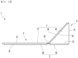
- FIG. 13 is a side view illustrating further another example of the display device for the vehicle according to the present embodiment
- FIG. 14 is a side view illustrating a state in which the display device for the vehicle or another example of the display module varies according to the present embodiment.
- the display panel 2 may be a flexible display panel, and the cover window 3 may be bendable or foldable.
- the cover window 3 may include a flat plate portion 31', a prism portion 34' that is thicker than the flat plate portion 31', and a connection body 38 connecting the flat plate portion 31' to the prism portion 34', and the connection body 38 may include a multi-link 39.
- the cover window 3 may be similar to the cover window illustrated in (b) of FIG. 6 , and the connection body 38 may include a boundary part 38A and a cover portion 38B, and may further include a multi-section link 39.
- the multi-link 39 may be connected to each of the flat plate portion 31' and the boundary part 38A.
- the multi-link 39 may include a plurality of unit links 39a, 39b, 39c, and 39d sequentially connected in a row.
- One of the plurality of unit links 39a, 39b, 39c, and 39d may be connected to the flat plate 31', and another of the plurality of unit links 39a, 39b, 39c, and 39d may be connected to the boundary part 38A.
- the display device for the vehicle may further include a tilting mechanism (not shown).
- the tilting mechanism may be connected to the flat plate portion 31' or to an area of the display panel 2 facing the flat plate portion 31'.
- An example of the tilting mechanism may include a tilting driving source such as a tilting motor connected to an area of the flat plate portion 31' or display panel 2, which faces the flat plate portion 31'.
- the tilting mechanism may rotate the flat plate 31' horizontally, as illustrated in (a) of FIG. 14 , and may rotate the flat plate 31' to be inclined with respect to a horizontal plane, as illustrated in (b) of FIG. 14 .
- image light may be emitted to a plurality of points WS1 and WS2 of the windshield WS, as illustrated in FIG. 13 .
- FIG. 15 is a side view illustrating a modified example of the example of the display device for the vehicle according to the present embodiment.
- a modified example of the display device for the vehicle may include a first panel 2A facing the total reflection area R and a second panel facing the transmission area P.
- Each of the first panel 2A and the second panel 2B may be a liquid crystal display (LCD) or an organic light emitting diode (OLED).
- LCD liquid crystal display
- OLED organic light emitting diode
- the type of display panel 2 is not limited, and various types may be applied.
- the first panel 2A and the second panel 2B may operate independently of each other and may operate to display different information.
- the first panel 2A and the second panel 2B may be coupled to the cover window 3 illustrated in (a) of FIG. 6 , may be coupled to the cover window 3 illustrated in (b) of FIG. 6 , may be coupled to the cover window 3 illustrated in (c) of FIG. 6 , and may be coupled to the cover window 3 illustrated in FIG. 14 .
- the first panel 2A and the second panel 2B may be coupled to the cover window 3 while being spaced apart from each other.
- the first panel 2A may face an incident surface 36 of each of the prism portions 34 and 34', and the second panel 2B may face an incident surface 32 of the flat plate portions 31 and 31'.
- a modified example of the display device for the vehicle may be the same as or similar to the example of the display device for the vehicle or further another example of the display device for the vehicle in other configurations or operations except for the display panel 2', and hereinafter, to avoid duplicated descriptions, the same symbols are used, and detailed descriptions thereof will be omitted.
Landscapes
- Engineering & Computer Science (AREA)
- Mechanical Engineering (AREA)
- Physics & Mathematics (AREA)
- Chemical & Material Sciences (AREA)
- Combustion & Propulsion (AREA)
- Transportation (AREA)
- General Physics & Mathematics (AREA)
- Optics & Photonics (AREA)
- Fittings On The Vehicle Exterior For Carrying Loads, And Devices For Holding Or Mounting Articles (AREA)
Abstract
Description
- The present invention relates to a display device for a vehicle.
- An example of a display device for a vehicle includes a video device for a vehicle that is disclosed in
Korean Patent Publication No. 10-2018-0004633 A (published on January 12, 2018 - The present embodiment provides a display device for a vehicle, which is capable of providing two displays with a simple structure.
- A display device for a vehicle according to the present embodiment may include a display module provided with a display panel and a cover window disposed on one surface of the display panel, and a drive mechanism configured to lay down the display module or stand up the display module.
- The cover window may include a total reflection area on which an image emitted from the display panel is totally reflected, and a transmission area on which the image emitted from the display panel is transmitted.
- A surface area of the total reflection area may be less than that of the transmission area.
- The drive mechanism may be performed in a plurality of modes.
- The plurality of modes may include a first mode in which an emission surface of the total reflection area faces backward, and a second mode in which an emission surface of the transmission area faces backward.
- In the first mode, the emission surface of the transmission area may face upward.
- In the second mode, the emission surface of the total reflection area may face downward.
- The cover window may include: a flat plate portion comprising the transmission area; and a prism portion disposed on one end of the flat plate portion and comprising the total reflection area.
- The display module may further include a cover decoration disposed on the cover window.
- The drive mechanism may be connected to the cover decoration.
- An example of the drive mechanism may include a rotary motor configured to rotate the cover decoration.
- Another example of the drive mechanism may include: a rotary motor connected to a rotation shaft disposed on the cover decoration; a bearing through which the rotation shaft passes; a pinion to which an outer circumference of the bearing is fixed; a rack with which the pinion is engaged; a moving drive gear engaged with the pinion; and a moving motor connected to the moving drive gear.
- The moving drive gear may be spaced apart from the rack in a vertical direction.
- The cover window may include: a flat plate portion; a prism portion that is thicker than the flat plate portion; and a connection body configured to connect the flat plate portion to the prism portion.
- The connection body may include a multi-link in which a plurality of unit links are sequentially connected in a row.
- The display panel may include a flexible display panel.
- The display panel may include: a first panel facing the total reflection area; and a second panel facing the transmission area.
- According to the present embodiment, the convenience may be improved by providing the two screens having the different sizes with one display device for the vehicle.
- In addition, when the vehicle is in the normal driving, the display device for the vehicle may display the small screen having the small size, and when the vehicle is stopped or driving autonomously, the display device for the vehicle may display the main screen having the large size, and thus, the frequency of use and the utilization of the display device for the vehicle may be high.
- In addition, the small screen having the small size and the large screen that is visible through the windshield may be provided through one display device to improve the utilization and minimize the number of display devices installed in the vehicle.
-
-
FIG. 1 is a side view when an example of a display device for a vehicle is a small display according to the present embodiment, -
FIG. 2 is a perspective view when the example of the display device for the vehicle is the small display according to the present embodiment, -
FIG. 3 is a side view when an example of the display device for the vehicle is a main display according to the present embodiment, -
FIG. 4 is a perspective view when the example of the display device for the vehicle is the main display according to the present embodiment, -
FIG. 5 is a perspective view illustrating an example of a cover window according to the present embodiment, -
FIG. 6 is an enlarged cross-sectional view illustrating various examples of the cover window according to the present embodiment, -
FIG. 7 is a cross-sectional view illustrating various examples of a prism portion according to the present embodiment, -
FIG. 8 is a side view illustrating a modified example of the example of the display device for the vehicle according to the present embodiment, -
FIG. 9 is a perspective view the modified example of the example of the display device for the vehicle according to the present embodiment, -
FIG. 10 is a side view illustrating an example in which a display module of another example of the display device for the vehicle slidably moves and rotates according to the present embodiment, -
FIG. 11 is a perspective view of a drive mechanism as another example of the display device for the vehicle according to the present embodiment, -
FIG. 12 is a control block diagram illustrating another example of the display device for the vehicle according to the present embodiment, -
FIG. 13 is a side view illustrating further another example of the display device for the vehicle according to the present embodiment, -
FIG. 14 is a side view illustrating a state in which the display device for the vehicle or another example of the display module varies according to the present embodiment, and -
FIG. 15 is a side view illustrating a modified example of the example of the display device for the vehicle according to the present embodiment. - Hereinafter, detailed embodiments will be described in detail with reference to the accompanying drawings.
-
FIG. 1 is a side view when an example of a display device for a vehicle is a small display according to the present embodiment,FIG. 2 is a perspective view when the example of the display device for the vehicle is the small display according to the present embodiment,FIG. 3 is a side view when an example of the display device for the vehicle is a main display according to the present embodiment,FIG. 4 is a perspective view when the example of the display device for the vehicle is the main display according to the present embodiment, andFIG. 5 is a perspective view illustrating an example of a cover window according to the present embodiment. - An example of a display device for a vehicle may include a
display module 1. - The
display module 1 may include adisplay panel 2 and acover window 3. - The
display panel 2 may be a liquid crystal display (LCD) or an organic light emitting diode (OLED). The type ofdisplay panel 2 is not limited, and various types may be applied. - The
cover window 3 may be disposed on one surface of thedisplay panel 2. - As illustrated in
FIG. 1 , when thedisplay panel 2 lays down, thecover window 3 may be disposed on a top surface of thedisplay panel 2. - As illustrated in
FIG. 3 , when thedisplay panel 2 stands up, thecover window 3 may be disposed on a rear surface of thedisplay panel 2. - The
cover window 3 may include a total reflection area R and a transmission area P. - The
cover window 3 may lay down or stand up together with thedisplay panel 2. - The total reflection area R may be an area on which an image emitted from the
display panel 2 is totally reflected when thecover window 3 lays down, as illustrated inFIGS. 1 and 2 . - The transmission area P may be an area through which the image emitted from the
display panel 2 is transmitted when thecover window 3 stands up, as illustrated inFIGS. 3 and 4 . - As illustrated in
FIG. 1 , when thecover window 3 lays down, the total reflection area R may be disposed in a row in a forward and backward direction X. When thecover window 3 lays down, the transmission area P may be disposed in front of the total reflection area R, and the total reflection area R may be disposed behind the transmission area P, as illustrated inFIG. 1 . - As illustrated in
FIG. 3 , when thecover window 3 stands up, the total reflection area R may be disposed in a row in a vertical direction Z. When thecover window 3 stands up, the transmission area P may be disposed above the total reflection area R, and the total reflection area R may be disposed below the transmission area P, as illustrated inFIG. 3 . - The image emitted from the
display panel 2 may be totally reflected backward by the total reflection area R. As illustrated inFIGS. 1 and 2 , when thecover window 3 lays down, the total reflection area R may provide a screen to a driver E (eye box) riding in the vehicle. - The image emitted from the
display panel 2 may be emitted backward through the transmission area P. As illustrated inFIGS. 3 and 4 , when thecover window 3 stands up, the transmission area P may provide a screen to the driver E (eye box) riding in the vehicle. - A surface area of the total reflection area R may be less than that of the transmission area P.
- The
display module 1 may provide a small display or server screen, which has a small size and has a total reflection area R facing backward when thecover window 3 lays down as illustrated inFIGS. 1 and 2 . - The
display module 1 may have a main display or large screen, which has a large size and has a transmission area P facing backward when thecover window 3 lays down as illustrated inFIGS. 3 and 4 . - The
cover window 3 may include aflat plate portion 31 and aprism portion 34. - The
flat plate portion 31 may include a transmission area P. - As illustrated in
FIGS. 3 and 4 , theflat plate portion 31 may have a front surface as anincident surface 32 and a rear surface as anemission surface 33 when thecover window 3 stands up. - The
flat plate portion 31 may emit the image incident from the front to the rear when thecover window 3 stands up. - The
prism portion 34 may be disposed on one end of theflat plate portion 31. Theprism portion 34 may be disposed on a rear end of theflat plate portion 31 when thecover window 3 lays down. Theprism portion 34 may be disposed on a lower end of theflat plate portion 31 when the cover window stands up. - The
prism portion 34 may include a total reflection area R. - As illustrated in
FIGS. 1 and 2 , theprism portion 34 may have a bottom surface as anincident surface 35, and a rear surface anemission surface 36 when thecover window 3 lays down. Theprism portion 34 may include an inclined surface when thecover window 3 lays down and may be atotal reflection surface 37 that totally reflects the image backward. - The
prism portion 34 may reflect the image, which is incident from the lower side, backward from the total reflection surface 37when thecover window 3 lays down and may reflect the image, which is reflected from thetotal reflection surface 37, backward. - A material of the
cover window 3 having theprism portion 34 may be a transparent ceramic series (glass, quartz, etc.) or a transparent polymer series (acrylic, PS, epoxy, PC, etc.). - The
prism portion 34 may not undergo any separate surface treatment applied to thetotal reflection surface 37 and may also undergo surface treatment applied to thetotal reflection surface 37 such as deposition or printing to improve brightness, etc. - The
display module 1 may further include a cover decoration 4 as illustrated inFIGS. 3 and 4 . - The cover decoration 4 may be disposed on the
cover window 3. The cover decoration 4 may surround an edge of thecover window 3. The cover decoration 4 may be coupled to at least one of thedisplay panel 2 or thecover window 3, and may be integrated with thedisplay panel 2 and thecover window 3. Thedisplay panel 2 and thecover window 3 may be coupled by thecover window 3. - The cover decoration 4 may surround both left and right ends of the
flat plate 31. - The cover decoration 4 may surround both left and right ends of the
prism portion 34. - An example of the display device for the vehicle may further include a
display module 1, particularly adrive mechanism 5 that lays down or stand up thedisplay panel 2 andwindow 3. - A first position at which the
display module 1 lays down may be defined as a position at which thedisplay module 1 is disposed horizontally or a position at which thedisplay module 1 is disposed to be inclined close to a horizontal plane. - A second position at which the
display module 1 stands up may be defined as a position where thedisplay module 1 is disposed vertically or a position at which thedisplay module 1 is disposed to be inclined close to the vertical plane. - An example of a
drive mechanism 5 may be a rotary mechanism that rotates thedisplay module 1 around arotation shaft 42. - The
drive mechanism 5 may be connected to the cover decoration 4 and may rotate the cover decoration 4, and thedisplay panel 2 and thecover window 3 may rotate together with the cover decoration 4. - An example of the
drive mechanism 5 may be a rotary motor that rotates the cover decoration 4. - The
rotation shaft 42 may be disposed at one of left and right sides of the cover decoration 4. Therotation shaft 42 may be disposed to protrude from a side surface of the cover decoration 4. - The rotary motor, which is the
drive mechanism 5, may be disposed next to the cover decoration 4 and connected to arotation shaft 42 to rotate the cover decoration 4. - An example of the display device for the vehicle may further include a
mounter 6 mounted on the vehicle. The rotary motor may be disposed on themounter 6 and supported by themounter 6. - The
drive mechanism 5 may perform a plurality of modes. The plurality of modes may include a first mode and a second mode. - The first mode may be a mode in which the
display panel 2 and thecover window 3 lay down as illustrated inFIGS. 1 and 2 . The first mode may be a mode in which theemission surface 36 of the total reflection area R faces backward. The first mode may be a mode in which theemission surface 33 of the transmission area R faces upward. - In the first mode of the
drive mechanism 5, thedisplay panel 2 may emit image light onto the total reflection area R, and the image light emitted from thedisplay panel 2 may be totally reflected by thetotal reflection surface 37 and then emitted backward. - The second mode may be a mode in which the
display panel 2 and thecover window 3 stand up as illustrated inFIGS. 3 and 4 . The second mode may be a mode in which the emission surface of the transmission area R faces backward. The second mode may be a mode in which the emission surface of the total reflection area R faces downward. - In the second mode of the
drive mechanism 5, thedisplay panel 2 may emit image light onto the transmission area P, and the image light emitted from thedisplay panel 2 may be transmitted through theemission surface 33 and then emitted backward. - An example of the display device for the vehicle may further include a controller that controls the rotary motor.
- The controller may control the
display panel 2 and thedrive mechanism 5 in different modes depending on the vehicle's driving mode (stop, low-speed driving, high-speed driving, etc.). - The
display panel 2 may display vehicle driving information such as P (parking), R (reverse), N (neutral), and D (drive). - The
display panel 2 may display schedule information such as reservation information. - The
display panel 2 may display vehicle's speed information in numerical form, etc. - The
display panel 2 may include direction information such as left turn, right turn, and straight ahead, as well as distance information. - The
display panel 2 may display map information such as a vehicle's final destination or an altitude change to a final destination. - The
display panel 2 may display vehicle driving information, schedule information, vehicle speed information, direction information, distance information, etc., and image light including vehicle driving information, schedule information, vehicle speed information, direction information, distance information, etc. may be directed backward through the total reflection area R when thecover window 3 lays down, as illustrated inFIG. 2 . - The
display panel 2 may display map information, etc., and image light including map information, etc. may be directed backward through the transmission area P while thecover window 3 stands up, as illustrated inFIG. 4 . -
FIG. 6 is an enlarged cross-sectional view illustrating various examples of the cover window according to the present embodiment. - In an example of the
cover window 3, as illustrated (a) ofFIG. 6 , aflat plate portion 31 and aprism portion 34 may be integrated with each other, and theprism portion 34 may be thicker than theflat plate portion 31. - Another example of the
cover window 3 may include, as illustrated (b) ofFIG. 6 , a flat plate portion 31', a prism portion 34', and aconnection body 38, and the prism portion 34' may be thicker than the flat plate portion 31'. - The
connection body 38 may connect the flat plate portion 31' to the prism portion 34'. The flat plate portion 31' and the prism portion 34' may be manufactured separately and connected by theconnection body 38. - The
connection body 38 may be connected to one end of the flat plate portion 31' and may cover one surface of the prism portion 34'. - The
connection body 38 may include aboundary part 38A disposed between the flat plate portion 31' and the prism portion 34', and acover portion 38B extending from theboundary part 38A to cover one surface of the prism portion 34'. - Another example of a
cover window 3 may include aflat plate portion 31" and aprism portion 34", as illustrated in (c) ofFIG. 6 , and theprism portion 34" may be attached to one surface of theflat portion 3", and theprism portion 34" may be thicker than theflat plate portion 31". - An
incident surface 35 of theprism portion 34" may be attached to one surface of theflat plate portion 31" by an adhesive means such as a transparent adhesive. - The
flat plate portion 31" may include an overlapping area O and a non-overlapping area NO. - The overlapping area O may be disposed between the
display panel 2 and theprism portion 34" and may be an area overlapping each of thedisplay panel 2 and theprism portion 34". - The non-overlapping area NO may be an area that overlaps the
display panel 2 and does not overlap theprism portion 34". -
FIG. 7 is a cross-sectional view illustrating various examples of the prism portion according to the present embodiment, - An example of the
prism portion 34 may be configured as a right-angle prism that internally totally reflects image light at a right angle, as illustrated in (a) ofFIG. 7 . - Another example of the
prism portion 34 may be configured as a penta prism that internally totally reflects image light plurality of times, as illustrated in (b) ofFIG. 7 . - Further another example of the
prism portion 34 may be a dove prism used to invert the top and bottom of an image, as illustrated in (c) ofFIG. 7 . -
FIG. 8 is a side view illustrating a modified example of the example of the display device for the vehicle according to the present embodiment.FIG. 9 is a perspective view of the modified example of the example of the display device for the vehicle according to the present embodiment. - In one example of the modified example of the display device for the vehicle, as illustrated in
FIGS. 8 and9 , when thecover window 3 lays down, thedisplay panel 2 may display information, and thedisplay panel 2 may emit image light to theflat plate portion 31 and theprism portion 34. - The image light emitted from the
flat plate portion 31 may be directed upward after passing through theflat plate portion 31 and may be directed toward a windshield WS of the vehicle. Thedisplay panel 2 may be used as a light source for a head-up display HUD, and a user E may recognize a virtual image formed in front of the windshield WS and a screen of the main display. - The image light emitted from the
prism portion 34 may be emitted backward after being totally reflected by theprism portion 34, and the user E may recognize the screen of the small display expressed through theprism portion 34. - In the first mode of the
drive mechanism 5, thedisplay panel 2 may emit image light onto the total reflection area R and the transmission area P, and the image light emitted from thedisplay panel 2 onto the total reflection area R may be totally reflected from thetotal reflection surface 37 and then emitted backward, and also, the image light emitted from thedisplay panel 2 onto the transmission area P may be directed toward the wind shield WS after being transmitted through thetransmission area 33. - The modified example of the example of the display device for the vehicle may be the same as or similar to the example of the display device for the vehicle in terms of its configuration and operation, except that the
display panel 2 emits image light onto the total reflection area R and the transmission area P in the first mode of thedrive mechanism 5, and thus, the same symbols are used, and detailed descriptions thereof will be omitted. -
FIG. 10 is a side view illustrating an example in which a display module of another example of the display device for the vehicle slidably moves and rotates according to the present embodiment,FIG. 11 is a perspective view of a drive mechanism as another example of the display device for the vehicle according to the present embodiment, andFIG. 12 is a control block diagram illustrating another example of the display device for the vehicle according to the present embodiment. - Another example of a drive mechanism 5' may rotate the
display module 1 as well as move thedisplay module 1 linearly. - The drive mechanism 5' may slide the
display module 1 in a forward and backward direction X after rotating thedisplay module 1, may slide thedisplay module 1 in the forward and backward direction X to rotate thedisplay module 1, and may rotate thedisplay module 1 to slide thedisplay module 1 in the forward and backward direction X. - The drive mechanism 5' may be a
rotary mechanism 52 connected to arotation shaft 42 disposed on a cover decoration 4. An example of therotary mechanism 52 may be arotary motor 52 connected to therotation shaft 42, and thus, therotary mechanism 52 and therotary motor 52 may be described by using the same symbol. - The
rotary motor 52 may be connected to therotation shaft 42 to rotate therotation shaft 42. When therotary motor 52 is driven, thedisplay module 1 may be rotated around therotation shaft 42. - The drive mechanism 5' may include a moving mechanism that moves the
rotation shaft 42 linearly. - An example of the moving mechanism may include a
bearing 53 through which therotation shaft 42 passes, apinion 55 to which an outer circumference of thebearing 53 is fixed, a movingdrive gear 56 engaged with thepinion 55, a movingmotor 57 connected to the movingdrive gear 56, and arack 58 engaged with thepinion 55. - An example of the
bearing 53 may be a ball bearing, and thebearing 53 may include an inner ring, an outer ring, and a plurality of balls disposed between the inner ring and the outer ring. An inner circumference of the inner ring may be an inner circumference of thebearing 53, and an outer circumference of the outer ring may be an outer circumference of thebearing 53. - The
rotation shaft 42 may pass through the inner ring of thebearing 53. An outer circumference of therotation shaft 42 may be fixed to be in close contact with the inner circumference of the inner ring of thebearing 53. - The
bearing 53 may be disposed inside thepinion 55. The outer ring of thebearing 53 may be fixed to the inner circumference of thepinion 55. - The
pinion 55 may be a bearing-fixed gear to which thebearing 53 is fixed. Thepinion 55 may be a hollow. An inner circumference of thepinion 55 may be coupled to the outer circumference of thebearing 53, especially the outer circumference of the outer ring. A gear that is engaged with the gear of therack 58 may be disposed on the outer circumference of thepinion 55. The gear disposed on the outer circumference of thepinion 55 may be engaged with the gear disposed on the outer circumference of the movingdrive gear 56. - The moving
drive gear 56 may be spaced apart from therack 58 in a vertical direction Z at an upper side of therack 58 and may rotate thepinion 55. - The moving
drive gear 56 may rotate around thedrive shaft 56a. Thedrive shaft 56a may be integrated with the movingdrive gear 56 or connected to a rotation center of the movingdrive gear 56. - The moving
motor 57 may be connected to thedrive shaft 56a to rotate the movingdriving gear 56. - The
rack 58 may be disposed lengthily in the forward and backward direction X on the vehicle ormounter 6 and may be provided with a gear on a top surface thereof. - The
rotation shaft 42 may be perpendicular to a longitudinal direction of therack 58, and a portion of therotation shaft 42 may extend upward toward therack 58. - A drive mechanism 5' may include a motor mounter (not shown) on which a
rotary motor 52 and a movingmotor 57 are installed. The motor mounter may be supported on themounter 6 and may move linearly together with thepinion 55 when thepinion 55 moves linearly. - When the moving
motor 57 is driven, the movingdrive gear 56 may rotate to rotate thepinion 55, thepinion 55 may move linearly in the forward and backward direction X along therack 58, and therotation shaft 42 passing through thebearing 53 may move linearly together with thepinion 56. Therotation shaft 42 may move linearly along therack 58 in the longitudinal direction of therack 58, and thedisplay module 1 may move linearly along therack 58. - The controller 7 may control the
display panel 2, therotary motor 52, and the movingmotor 57. - An example of the controller 7 may control the
display panel 2, therotary motor 52, and the movingmotor 57 according to an input from an input unit 8 that receives a user's command. - Another example of the controller 7 may receive a signal from a vehicle's microcomputer and may control the
display panel 2, therotary motor 52, and the movingmotor 57 according to a command transmitted from the vehicle's microcomputer. -
FIG. 13 is a side view illustrating further another example of the display device for the vehicle according to the present embodiment, andFIG. 14 is a side view illustrating a state in which the display device for the vehicle or another example of the display module varies according to the present embodiment. - In further another example of the display device for the vehicle, the
display panel 2 may be a flexible display panel, and thecover window 3 may be bendable or foldable. - The
cover window 3 may include a flat plate portion 31', a prism portion 34' that is thicker than the flat plate portion 31', and aconnection body 38 connecting the flat plate portion 31' to the prism portion 34', and theconnection body 38 may include a multi-link 39. - The
cover window 3 may be similar to the cover window illustrated in (b) ofFIG. 6 , and theconnection body 38 may include aboundary part 38A and acover portion 38B, and may further include amulti-section link 39. - The multi-link 39 may be connected to each of the flat plate portion 31' and the
boundary part 38A. - The multi-link 39 may include a plurality of
unit links - One of the plurality of
unit links unit links boundary part 38A. - Further another example of the display device for the vehicle may further include a tilting mechanism (not shown).
- The tilting mechanism may be connected to the flat plate portion 31' or to an area of the
display panel 2 facing the flat plate portion 31'. An example of the tilting mechanism may include a tilting driving source such as a tilting motor connected to an area of the flat plate portion 31' ordisplay panel 2, which faces the flat plate portion 31'. - The tilting mechanism may rotate the flat plate 31' horizontally, as illustrated in (a) of
FIG. 14 , and may rotate the flat plate 31' to be inclined with respect to a horizontal plane, as illustrated in (b) ofFIG. 14 . - In further another example of the display device for the vehicle, as the flat plate portion 31' is tilted, image light may be emitted to a plurality of points WS1 and WS2 of the windshield WS, as illustrated in
FIG. 13 . -
FIG. 15 is a side view illustrating a modified example of the example of the display device for the vehicle according to the present embodiment. - A modified example of the display device for the vehicle may include a
first panel 2A facing the total reflection area R and a second panel facing the transmission area P. - Each of the
first panel 2A and thesecond panel 2B may be a liquid crystal display (LCD) or an organic light emitting diode (OLED). The type ofdisplay panel 2 is not limited, and various types may be applied. - The
first panel 2A and thesecond panel 2B may operate independently of each other and may operate to display different information. - The
first panel 2A and thesecond panel 2B may be coupled to thecover window 3 illustrated in (a) ofFIG. 6 , may be coupled to thecover window 3 illustrated in (b) ofFIG. 6 , may be coupled to thecover window 3 illustrated in (c) ofFIG. 6 , and may be coupled to thecover window 3 illustrated inFIG. 14 . - The
first panel 2A and thesecond panel 2B may be coupled to thecover window 3 while being spaced apart from each other. - The
first panel 2A may face anincident surface 36 of each of theprism portions 34 and 34', and thesecond panel 2B may face anincident surface 32 of theflat plate portions 31 and 31'. - A modified example of the display device for the vehicle may be the same as or similar to the example of the display device for the vehicle or further another example of the display device for the vehicle in other configurations or operations except for the display panel 2', and hereinafter, to avoid duplicated descriptions, the same symbols are used, and detailed descriptions thereof will be omitted.
- The above-disclosed subject matter is to be considered illustrative, and not restrictive, and the appended claims are intended to cover all such modifications, enhancements, and other embodiments, which fall within the true spirit and scope of the present invention.
- Thus, the embodiment of the present invention is to be considered illustrative, and not restrictive, and the technical spirit of the present invention is not limited to the foregoing embodiment.
- Therefore, the scope of the present invention is defined not by the detailed description of the invention but by the appended claims, and all differences within the scope will be construed as being included in the present invention.
Claims (13)
- A display device for a vehicle, comprising:a display module provided with a display panel and a cover window disposed on one surface of the display panel; anda drive mechanism configured to lay down the display module or stand up the display module,wherein the cover window comprises:a total reflection area on which an image emitted from the display panel is totally reflected; anda transmission area on which the image emitted from the display panel is transmitted.
- The display device according to claim 1, wherein a surface area of the total reflection area is less than a surface area of the transmission area.
- The display device according to claim 1, wherein the drive mechanism is performed in a plurality of modes,
wherein the plurality of modes comprises:a first mode in which an emission surface of the total reflection area faces backward; anda second mode in which an emission surface of the transmission area faces backward. - The display device according to claim 3, wherein, in the first mode, the emission surface of the transmission area faces upward, and
in the second mode, the emission surface of the total reflection area faces downward. - The display device according to claim 1, wherein the cover window comprises:a flat plate portion comprising the transmission area; anda prism portion disposed on one end of the flat plate portion and comprising the total reflection area.
- The display device according to claim 1, wherein the display module further comprises a cover decoration disposed on the cover window,
wherein the drive mechanism is connected to the cover decoration. - The display device according to claim 1, wherein the drive mechanism comprises a rotary motor configured to rotate the cover decoration.
- The display device according to claim 1, wherein the drive mechanism comprises:a rotary motor connected to a rotation shaft disposed on the cover decoration;a bearing through which the rotation shaft passes;a pinion to which an outer circumference of the bearing is fixed;a rack with which the pinion is engaged;a moving drive gear engaged with the pinion; anda moving motor connected to the moving drive gear.
- The display device according to claim 8, wherein the moving drive gear is spaced apart from the rack in a vertical direction.
- The display device according to claim 1, wherein the cover window comprises:a flat plate portion;a prism portion that is thicker than the flat plate portion; anda connection body configured to connect the flat plate portion to the prism portion.
- The display device according to claim 10, wherein the connection body comprises a multi-link in which a plurality of unit links are sequentially connected in a row.
- The display device according to claim 10, wherein the display panel comprises a flexible display panel.
- The display device according to claim 1, wherein the display panel comprises:a first panel facing the total reflection area; anda second panel facing the transmission area.
Applications Claiming Priority (2)
| Application Number | Priority Date | Filing Date | Title |
|---|---|---|---|
| KR20220111681 | 2022-09-02 | ||
| PCT/KR2022/021121 WO2024048867A1 (en) | 2022-09-02 | 2022-12-22 | Display device for vehicle |
Publications (2)
| Publication Number | Publication Date |
|---|---|
| EP4545335A1 true EP4545335A1 (en) | 2025-04-30 |
| EP4545335A4 EP4545335A4 (en) | 2025-11-05 |
Family
ID=90098078
Family Applications (1)
| Application Number | Title | Priority Date | Filing Date |
|---|---|---|---|
| EP22957543.6A Pending EP4545335A4 (en) | 2022-09-02 | 2022-12-22 | DISPLAY DEVICE FOR A VEHICLE |
Country Status (5)
| Country | Link |
|---|---|
| US (1) | US20260048661A1 (en) |
| EP (1) | EP4545335A4 (en) |
| KR (1) | KR20250012597A (en) |
| CN (1) | CN119604424A (en) |
| WO (1) | WO2024048867A1 (en) |
Family Cites Families (11)
| Publication number | Priority date | Publication date | Assignee | Title |
|---|---|---|---|---|
| JPH10963A (en) * | 1996-04-16 | 1998-01-06 | Harness Sogo Gijutsu Kenkyusho:Kk | Vehicle display device |
| KR101663728B1 (en) * | 2013-08-26 | 2016-10-07 | 삼성전자주식회사 | foldable electronic device having flexible display |
| RU2017105422A (en) * | 2014-07-22 | 2018-08-26 | Навди Инк. | COMPACT WINDSHIELD INDICATION SYSTEM |
| JP2017109577A (en) * | 2015-12-16 | 2017-06-22 | 株式会社ユピテル | Information display system |
| KR101904604B1 (en) | 2016-07-04 | 2018-11-30 | 문명일 | Image device for vehicle |
| KR101846737B1 (en) * | 2016-11-16 | 2018-05-18 | 덴소코리아일렉트로닉스 주식회사 | Hud integral type cluster system for vehicle |
| DE102019125596B3 (en) * | 2019-09-24 | 2020-08-27 | Audi Ag | Double-sided tiltable display for vehicles |
| DE102020103964A1 (en) * | 2020-02-14 | 2021-08-19 | Bayerische Motoren Werke Aktiengesellschaft | Field of view display device with a height offset device for a vehicle |
| DE102020112938B3 (en) * | 2020-05-13 | 2021-07-29 | Audi Aktiengesellschaft | Arrangement for an interior of a vehicle and method for providing display content |
| JP2021189302A (en) * | 2020-05-29 | 2021-12-13 | 株式会社デンソー | Display device |
| KR20220091696A (en) * | 2020-12-23 | 2022-07-01 | 현대모비스 주식회사 | Display Apparatus for Vehicle And Control Method Therefor |
-
2022
- 2022-12-22 KR KR1020247041526A patent/KR20250012597A/en active Pending
- 2022-12-22 CN CN202280098482.1A patent/CN119604424A/en active Pending
- 2022-12-22 EP EP22957543.6A patent/EP4545335A4/en active Pending
- 2022-12-22 WO PCT/KR2022/021121 patent/WO2024048867A1/en not_active Ceased
- 2022-12-22 US US19/099,626 patent/US20260048661A1/en active Pending
Also Published As
| Publication number | Publication date |
|---|---|
| KR20250012597A (en) | 2025-01-24 |
| CN119604424A (en) | 2025-03-11 |
| WO2024048867A1 (en) | 2024-03-07 |
| EP4545335A4 (en) | 2025-11-05 |
| US20260048661A1 (en) | 2026-02-19 |
Similar Documents
| Publication | Publication Date | Title |
|---|---|---|
| US11812200B2 (en) | Head-up display apparatus | |
| JP6408774B2 (en) | Head-up display device | |
| JP4490605B2 (en) | In-vehicle head-up display device | |
| JP5741251B2 (en) | Virtual image display device | |
| US11889646B2 (en) | Display device | |
| US20210349311A1 (en) | Head up display | |
| JP2018045143A (en) | Head-up display device | |
| US20210096392A1 (en) | Space three-dimensional imaging apparatus and method | |
| US20030214474A1 (en) | Display apparatus for a vehicle | |
| EP4545335A1 (en) | Display device for vehicle | |
| US20240324120A1 (en) | Display device and method for controlling display device | |
| EP3640720B1 (en) | Display apparatus | |
| US7165841B2 (en) | Stereoscopic image display apparatus | |
| CN114764196B (en) | Display device for vehicle | |
| US20230209736A1 (en) | Display device | |
| KR20190012422A (en) | Light control member and display device | |
| EP4491431A1 (en) | Display device for vehicle | |
| EP4617098A1 (en) | Display device for vehicle | |
| JP2008176232A (en) | Display device | |
| KR102896420B1 (en) | display device | |
| CN116101033A (en) | Anti-peeping glass assembly and vehicle | |
| US20250085547A1 (en) | Head-up display | |
| EP4556284A1 (en) | Vehicle display device | |
| US20260116185A1 (en) | Bendable display device | |
| EP4516557A1 (en) | Display device for vehicle |
Legal Events
| Date | Code | Title | Description |
|---|---|---|---|
| STAA | Information on the status of an ep patent application or granted ep patent |
Free format text: STATUS: THE INTERNATIONAL PUBLICATION HAS BEEN MADE |
|
| PUAI | Public reference made under article 153(3) epc to a published international application that has entered the european phase |
Free format text: ORIGINAL CODE: 0009012 |
|
| STAA | Information on the status of an ep patent application or granted ep patent |
Free format text: STATUS: REQUEST FOR EXAMINATION WAS MADE |
|
| 17P | Request for examination filed |
Effective date: 20250124 |
|
| AK | Designated contracting states |
Kind code of ref document: A1 Designated state(s): AL AT BE BG CH CY CZ DE DK EE ES FI FR GB GR HR HU IE IS IT LI LT LU LV MC ME MK MT NL NO PL PT RO RS SE SI SK SM TR |
|
| A4 | Supplementary search report drawn up and despatched |
Effective date: 20251008 |
|
| RIC1 | Information provided on ipc code assigned before grant |
Ipc: B60K 35/00 20240101AFI20251001BHEP Ipc: G02B 5/04 20060101ALI20251001BHEP Ipc: G03B 21/28 20060101ALI20251001BHEP Ipc: B60R 11/02 20060101ALI20251001BHEP Ipc: B60K 35/22 20240101ALI20251001BHEP Ipc: B60K 35/53 20240101ALI20251001BHEP Ipc: G02B 27/01 20060101ALI20251001BHEP Ipc: B60K 35/23 20240101ALI20251001BHEP Ipc: B60K 35/55 20240101ALI20251001BHEP Ipc: B60K 35/60 20240101ALI20251001BHEP Ipc: B60R 11/00 20060101ALN20251001BHEP |
|
| DAV | Request for validation of the european patent (deleted) | ||
| DAX | Request for extension of the european patent (deleted) |