EP4545197A1 - Press brake, press brake control device, and press brake control method - Google Patents
Press brake, press brake control device, and press brake control method Download PDFInfo
- Publication number
- EP4545197A1 EP4545197A1 EP23827110.0A EP23827110A EP4545197A1 EP 4545197 A1 EP4545197 A1 EP 4545197A1 EP 23827110 A EP23827110 A EP 23827110A EP 4545197 A1 EP4545197 A1 EP 4545197A1
- Authority
- EP
- European Patent Office
- Prior art keywords
- workpiece
- image
- abutment
- bending
- information
- Prior art date
- Legal status (The legal status is an assumption and is not a legal conclusion. Google has not performed a legal analysis and makes no representation as to the accuracy of the status listed.)
- Pending
Links
Images





Classifications
-
- B—PERFORMING OPERATIONS; TRANSPORTING
- B21—MECHANICAL METAL-WORKING WITHOUT ESSENTIALLY REMOVING MATERIAL; PUNCHING METAL
- B21D—WORKING OR PROCESSING OF SHEET METAL OR METAL TUBES, RODS OR PROFILES WITHOUT ESSENTIALLY REMOVING MATERIAL; PUNCHING METAL
- B21D5/00—Bending sheet metal along straight lines, e.g. to form simple curves
- B21D5/002—Positioning devices
-
- B—PERFORMING OPERATIONS; TRANSPORTING
- B21—MECHANICAL METAL-WORKING WITHOUT ESSENTIALLY REMOVING MATERIAL; PUNCHING METAL
- B21D—WORKING OR PROCESSING OF SHEET METAL OR METAL TUBES, RODS OR PROFILES WITHOUT ESSENTIALLY REMOVING MATERIAL; PUNCHING METAL
- B21D5/00—Bending sheet metal along straight lines, e.g. to form simple curves
- B21D5/004—Bending sheet metal along straight lines, e.g. to form simple curves with program control
-
- B—PERFORMING OPERATIONS; TRANSPORTING
- B21—MECHANICAL METAL-WORKING WITHOUT ESSENTIALLY REMOVING MATERIAL; PUNCHING METAL
- B21D—WORKING OR PROCESSING OF SHEET METAL OR METAL TUBES, RODS OR PROFILES WITHOUT ESSENTIALLY REMOVING MATERIAL; PUNCHING METAL
- B21D5/00—Bending sheet metal along straight lines, e.g. to form simple curves
- B21D5/02—Bending sheet metal along straight lines, e.g. to form simple curves on press brakes without making use of clamping means
-
- B—PERFORMING OPERATIONS; TRANSPORTING
- B23—MACHINE TOOLS; METAL-WORKING NOT OTHERWISE PROVIDED FOR
- B23Q—DETAILS, COMPONENTS, OR ACCESSORIES FOR MACHINE TOOLS, e.g. ARRANGEMENTS FOR COPYING OR CONTROLLING; MACHINE TOOLS IN GENERAL CHARACTERISED BY THE CONSTRUCTION OF PARTICULAR DETAILS OR COMPONENTS; COMBINATIONS OR ASSOCIATIONS OF METAL-WORKING MACHINES, NOT DIRECTED TO A PARTICULAR RESULT
- B23Q17/00—Arrangements for observing, indicating or measuring on machine tools
- B23Q17/24—Arrangements for observing, indicating or measuring on machine tools using optics or electromagnetic waves
- B23Q17/2409—Arrangements for indirect observation of the working space using image recording means, e.g. a camera
-
- B—PERFORMING OPERATIONS; TRANSPORTING
- B30—PRESSES
- B30B—PRESSES IN GENERAL
- B30B15/00—Details of, or accessories for, presses; Auxiliary measures in connection with pressing
- B30B15/26—Program-control arrangements
-
- G—PHYSICS
- G05—CONTROLLING; REGULATING
- G05B—CONTROL OR REGULATING SYSTEMS IN GENERAL; FUNCTIONAL ELEMENTS OF SUCH SYSTEMS; MONITORING OR TESTING ARRANGEMENTS FOR SUCH SYSTEMS OR ELEMENTS
- G05B19/00—Program-control systems
- G05B19/02—Program-control systems electric
- G05B19/04—Program control other than numerical control, i.e. in sequence controllers or logic controllers
- G05B19/042—Program control other than numerical control, i.e. in sequence controllers or logic controllers using digital processors
-
- G—PHYSICS
- G06—COMPUTING OR CALCULATING; COUNTING
- G06T—IMAGE DATA PROCESSING OR GENERATION, IN GENERAL
- G06T11/00—Two-dimensional [2D] image generation
- G06T11/60—Creating or editing images; Combining images with text
-
- G—PHYSICS
- G06—COMPUTING OR CALCULATING; COUNTING
- G06T—IMAGE DATA PROCESSING OR GENERATION, IN GENERAL
- G06T7/00—Image analysis
- G06T7/0002—Inspection of images, e.g. flaw detection
- G06T7/0004—Industrial image inspection
-
- G—PHYSICS
- G05—CONTROLLING; REGULATING
- G05B—CONTROL OR REGULATING SYSTEMS IN GENERAL; FUNCTIONAL ELEMENTS OF SUCH SYSTEMS; MONITORING OR TESTING ARRANGEMENTS FOR SUCH SYSTEMS OR ELEMENTS
- G05B2219/00—Program-control systems
- G05B2219/30—Nc systems
- G05B2219/45—Nc applications
- G05B2219/45143—Press-brake, bending machine
Definitions
- the present disclosure relates to a press brake, a press brake control device, and a press brake control method.
- Patent Literature 1 describes that a camera is arranged at least above on the far side of an upper table of a press brake and an image as a work guide showing the position or movement of an abutment of a back gauge is superimposed on an image captured by the camera.
- Patent Literature 1 International Publication No. WO2020/041807
- a first aspect of one or more embodiments provides a press brake including: an upper table to be fitted with a punch; a lower table to be fitted with a die; an NC device configured to control bending of a workpiece by the punch and the die based on a processing program; a back gauge arranged on a back side of the lower table and comprising one or more abutments defining a position in a depth direction at a time of placing the workpiece on the die; a camera arranged on a back side of the upper table and configured to capture an image in a direction of the lower table; and a display device configured to display the image captured by the camera; wherein the NC device includes: an additional image generation unit configured to generate, based on shape information about the workpiece, position information about a position to place the workpiece in each of bending processes of the workpiece, abutment identification information identifying an abutment to be used in each of the bending processes, abutment coordinates in real space to position the abutment in each of the bending processes,
- the first aspect of one or more embodiments it is possible to display a superimposed image obtained by superimposing a workpiece shape image and an abutting area image on an image captured by a camera, on a display device. Therefore, an operator can visually recognize at which position of an abutment the operator should cause the workpiece to abut against the abutment.
- a second aspect of one or more embodiments provides a press brake control device including: a bending data extraction unit configured to extract, from a processing program for performing bending of a workpiece to be processed, shape information about the workpiece, position information about a position to place the workpiece in each of bending processes of the workpiece, abutment identification information identifying an abutment to be used in each of the bending processes, abutment coordinates in real space to position the abutment in each of the bending processes, and abutting area information indicating an area of the abutment to be abutted by the workpiece in each of the bending processes as bending data; an additional image generation unit configured to generate, based on the shape information about the workpiece, the position information about the workpiece, the abutment identification information, the abutment coordinates, and the abutting area information extracted by the bending data extraction unit, and coordinate conversion values for converting a position in real space in a direction of a lower table a camera captures an image of
- the second aspect of one or more embodiments it is possible to perform control to display a superimposed image obtained by superimposing a workpiece shape image and an abutting area image on an image captured by a camera, on a display device. Therefore, the operator can visually recognize at which position of the abutment the operator should cause the workpiece to abut against the abutment.
- a third aspect of one or more embodiments provides a press brake control method including: extracting from a processing program for performing, by an NC device configured to control bending of the workpiece, bending of a workpiece to be processed, shape information about the workpiece, position information about a position to place the workpiece in each of bending processes of the workpiece, abutment identification information identifying an abutment to be used in each of the bending processes, abutment coordinates in real space to position the abutment in each of the bending processes, and abutting area information indicating an area of the abutment to be abutted by the workpiece in each of the bending processes; generating, by the NC device, an additional image including a workpiece shape image showing a shape of the workpiece and an abutting area image showing the area of the abutment to be abutted by the workpiece, based on the shape information about the workpiece, the position information about the workpiece, the abutment identification information, the abutment coordinates,
- the third aspect of one or more embodiments it is possible to perform control to display a superimposed image obtained by superimposing a workpiece shape image and an abutting area image on an image captured by a camera, on a display device. Therefore, the operator can visually recognize at which position of the abutment the operator should cause the workpiece to abut against the abutment.
- the press brake control device According to the press brake, the press brake control device, and the press brake control method according to one or more embodiments, it is possible for the operator to perform bending of a workpiece while visually recognizing at which position of the abutment the operator should cause the workpiece to abut against the abutment in each bending process of the workpiece.
- a press brake includes: an upper table to be fitted with a punch; a lower table to be fitted with a die; an NC device configured to control bending of a workpiece by the punch and the die based on a processing program; a back gauge arranged on a back side of the lower table and comprising one or more abutments defining a position in a depth direction at a time of placing the workpiece on the die; a camera arranged on a back side of the upper table and configured to capture an image in a direction of the lower table; and a display device configured to display the image captured by the camera.
- the NC device includes an additional image generation unit and a superimposed image generation unit.
- the additional image generation unit generates, based on shape information about the workpiece, position information about a position to place the workpiece in each of bending processes of the workpiece, abutment identification information identifying abutments to be used in each of the bending processes, abutment coordinates in real space to position the abutments in each of the bending processes, and abutting area information indicating areas of the abutments to be abutted by the workpiece in each of the bending processes extracted from the processing program, and coordinate conversion values for converting a position in the real space the camera captures an image of to a position on the captured image, additional images to be added to the captured image, including a workpiece shape image showing a shape of the workpiece and abutting area images showing the areas of the abutments to be abutted by the workpiece.
- the superimposed image generation unit generates a superimposed image to be displayed on the display device by superimposing the additional images on the captured image.
- a press brake control device includes a bending data extraction unit, an additional image generation unit, and a superimposed image generation unit.
- the bending data extraction unit extracts, from a processing program for performing bending of a workpiece to be processed, shape information about the workpiece, position information about a position to place the workpiece in each of bending processes of the workpiece, abutment identification information identifying abutments to be used in each of the bending processes, abutment coordinates in real space to position the abutments in each of the bending processes, and abutting area information indicating areas of the abutments to be abutted by the workpiece in each of the bending processes as bending data.
- the additional image generation unit generates, based on the shape information about the workpiece, the position information about the workpiece, the abutment identification information, the abutment coordinates, and the abutting area information extracted by the bending data extraction unit, and coordinate conversion values for converting a position in real space in a direction of a lower table a camera captures an image of to a position on the image captured by the camera, the camera being placed on a backside of an upper table, and the coordinate conversion values being determined in advance and held in a holding unit, additional images including a workpiece shape image showing a shape of the workpiece and abutting area images showing the areas of the abutments to be abutted by the workpiece.
- the superimposed image generation unit generate a superimposed image obtained by superimposing the additional images on the captured image to generate a superimposed image to be displayed on a display device.
- an NC device configured to control bending of the workpiece extracts, from a processing program for performing bending of a workpiece to be processed, shape information about the workpiece, position information about a position to place the workpiece in each of bending processes of the workpiece, abutment identification information identifying abutments to be used in each of the bending processes, abutment coordinates in real space to position the abutments in each of the bending processes, and abutting area information indicating areas of the abutments to be abutted by the workpiece in each of the bending processes.
- the NC device generates, based on the shape information about the workpiece, the position information about the workpiece, the abutment identification information, the abutment coordinates, and the abutting area information, and coordinate conversion values for converting a position in real space in a direction of a lower table a camera captures an image of to a position on the image captured by the camera, the camera being placed on a backside of an upper table, and the coordinate conversion values being determined in advance and held in a holding unit, additional images including a workpiece shape image showing a shape of the workpiece and a abutting area image showing the areas of the abutments to be abutted by the workpiece.
- the NC device generates a superimposed image obtained by superimposing the additional images on the captured image to generate a superimposed image to be displayed on a display device.
- FIG. 1 shows an overall configuration of a press brake 100 according to one or more embodiments.
- the press brake 100 includes a numerical control (NC) device 10 that functions as a press brake control device.
- a processing program database 50 is connected via a network.
- the press brake 100 includes an upper table 1, a lower table 3, and right and left side panels 5R and 5L.
- An upper tool holder 2 is attached to the upper table 1, and a lower tool holder 4 is attached to the lower table 3.
- the upper table 1 is configured to be vertically moved by hydraulic cylinders 6R and 6L provided on the right and left.
- a punch Tp which is an upper tool
- a die Td which is a lower tool
- the upper tool holder 2 is integrally attached to the entire length of the lower end of the upper table 1
- an intermediate plate type in which a plurality of intermediate plates to be fitted with the punch Tp are attached in a longitudinal direction of the lower end of the upper table 1 may be adopted.
- the intermediate plates are also upper tool holders.
- To fit the punch Tp to the upper table 1 means to fit the punch Tp to the upper tool holder 2 or the intermediate plates.
- To fit the die Td to the lower table 3 means to fit the die Td to the lower tool holder 4.
- Two or more punches Tp may be fitted to the upper table 1 side by side, and two or more dies Td may be fitted to the lower table 3 side by side.
- a back gauge 40 is arranged on the back side of the lower table 3.
- the back gauge 40 is provided with abutments 42a and 42b that move in the left/right direction along a back gauge carriage 41. Though it is assumed here that the two abutments 42a and 42b are provided, there may be a case in which one, three, or four abutments are provided. An arbitrary abutment will be referred to as an abutment 42.
- the abutment 42 is configured to move both in the height direction and in the forward/backward direction.
- the abutment 42 moves to a position corresponding to the die Td.
- the operator places the workpiece W on the die Td in a manner of causing the end of the workpiece W on the far side to abut the abutment 42. That is, the abutment 42 acts to define the position of workpiece W in the forward/backward direction at the time of placing the workpiece W on the die Td.
- an operation pendant 7 which includes a display 71 and an operation unit 72 with a plurality of operation buttons, is attached via an arm 7a.
- the operation pendant 7 is connected to the NC device 10.
- the right and left side panels 5R and 5L are coupled via a coupling bar 51.
- the coupling bar 51 is located behind the upper table 1 and at upper parts of the right and left side panels 5R and 5L.
- a camera 20 is fitted to the lower surface of the coupling bar 51, in the center of the left/right direction of the coupling bar 51.
- the camera 20 is arranged on the back side of the upper table 1 to capture an image in the direction of the lower table 3. It is preferred that the camera 20 includes a fisheye lens so as to be capable of capturing an image from the right-side end to left-side end of the lower table 3. It is preferable that the camera 20 includes a fisheye lens, since this allows for capturing images of a wide range.
- the camera 20 may include a wide-angle lens or an ultra-wide-angle lens instead of the fisheye lens if it is possible to capture an image from the right-side end to left-side end of the lower table 3. An image captured by the camera 20 is supplied to the NC device 10.
- a fitting portion 301 for the tablet device 30 extending in the left/right direction is formed on the upper table 1. It is preferable that the tablet device 30 is configured such that the fitting position relative to the upper table 1 in the left/right direction can be changed along the fitting portion 301.
- the fitting portion 301 may be configured such that the tablet device 30 can be fitted into a recess portion thereof, for example, or may be configured such that the tablet device 30 can be fitted to the fitting portion 301 with a magnet, for example.
- the configuration for fitting the tablet device 30 to the upper table 1 and the configuration for causing the tablet device 30 to be movable in the left/right direction are not limited.
- the tablet device 30 is connected to the NC device 10.
- the NC device 10 and the tablet device 30 are connected via a wireless LAN.
- Wi-Fi which is a wireless LAN in conformity with the communication standard IEEE 802.11, can be used.
- the NC device 10 and the tablet device 30 may be connected via Bluetooth (registered trademark) which is an example of near field wireless communication standards. It is preferable that the NC device 10 and the tablet device 30 are connected to each other via wireless communication, since it is easy to move the tablet device 30, and it is also possible to remove the tablet device 30 from the fitting portion 301 for use.
- the NC device 10 and the tablet device 30, however, may be connected by wire.
- FIG. 2 is a block diagram showing the press brake 100 according to one or more embodiments. Operation of the press brake 100 will be described using FIG. 2 .
- the NC device 10 includes a processing program holding unit 11, a processing controller 12, a bending data extraction unit 13, a bending data holding unit 14, a coordinate conversion value holding unit 15, an additional image generation unit 16, a superimposed image generation unit 17, and a wireless communication unit 18.
- the processing controller 12 includes a slide controller 121 that controls the hydraulic cylinders 6R and 6L and a back gauge controller 122 that controls the back gauge 40.
- the camera 20 includes a fisheye lens 21.
- the tablet device 30 includes a wireless communication unit 31, an image display controller 32, and a display 33.
- the wireless communication units 18 and 31 communicate with each other via the wireless LAN or near field wireless communication described above.
- the processing program holding unit 11, the bending data holding unit 14, and the coordinate conversion value holding unit 15 can be constituted of a storage unit included in the NC device 10.
- the processing controller 12, the bending data extraction unit 13, the additional image generation unit 16, and the superimposed image generation unit 17 can be functionally formed by a central processing unit included in the NC device 10 executing software.
- the wireless communication unit 18 can be constituted of a circuit that executes wireless communication and an antenna.
- the wireless communication unit 31 can be constituted of a circuit that executes wireless communication and an antenna.
- the image display controller 32 can be functionally formed by a central processing unit included in the tablet device 30 executing software.
- the display 33 is a liquid crystal panel, for example.
- the processing program holding unit 11 holds a processing program read by the NC device 10 from the processing program database 50.
- the processing controller 12 controls processing of the workpiece W according to the processing program.
- the back gauge controller 122 controls the back gauge 40 to move the abutment 42 according to the processing program.
- the slide controller 121 controls the hydraulic cylinders 6R and 6L to slide the upper table 1 according to the processing program, in response to an operation of the foot switch 8.
- the bending data extraction unit 13 extracts bending data shown below from the processing program.
- the bending data extracted from the processing program includes shape information about the workpiece W, position information about a position to place the workpiece W in each bending process of the workpiece W, and bending line information showing a position of bending of the workpiece W in each process.
- FIG. 3 shows an example of the shape of the workpiece W to be bent by the press brake 100.
- the shape information about the workpiece W is represented by coordinate values identifying the shape of the workpiece W.
- the position information about the workpiece W is position information indicating where on the lower table 3 in the left/right direction and in the depth direction the workpiece W is to be placed.
- the position information about the workpiece W can be obtained from a three-dimensional model in the processing program.
- the workpiece W shown in FIG. 3 includes bending lines V1 to V4, and the bending data includes bending line information indicating the bending lines V1 to V4.
- the bending data includes bending order information indicating bending order of the bending lines V1 to V4.
- the bending data includes abutment identification information identifying the abutment 42 to be used in each bending process, abutment coordinates in real space where the abutment 42 is to be positioned in each bending process, and abutting area information indicating an area of the abutment 42 to be abutted by the workpiece W in each bending process.
- the abutment identification information is represented by a number identifying each of abutments 42 in various shapes.
- FIGS. 4A and 4B show first and second examples of the shape of the abutment 42, respectively.
- the abutment 42 of the first example shown in FIG. 4A is in a plate shape with a rectangular end on the distal end side.
- the abutment 42 of the second example shown in FIG. 4B includes a lower portion 421 and an upper portion 422, and semicircular recess portions are formed on the lower portion 421 and the upper portion 422. Which shape of abutment 42 is to be used is identified by the abutment identification information.
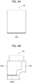
- FIGS. 5A and 5B show abutting areas to be butted by the workpiece W when the abutments 42 of the first and second examples shown in FIGS. 4A and 4B are used, respectively.
- the abutting area of the abutment 42 shown in FIG. 4A is a distal end surface 420 of the abutment 42
- the abutting area information is information indicating the position of the distal end surface 420 of the abutment 42.
- the abutting area of the abutment 42 shown in FIG. 4B is a distal end surface 4220 of the upper portion 422, for example, and the abutting area information is information indicating the position of the distal end surface 4220 of the upper portion 422.
- the bending data holding unit 14 holds the bending data extracted by the bending data extraction unit 13.
- the coordinate conversion value holding unit 15 holds the coordinate conversion values for converting a position in real space the camera 20 captures an image of to a position on the image captured by the camera 20.
- the coordinate conversion values can be constituted of a set of two-dimensional conversion values for converting two-dimensional coordinates in real space the camera 20 captures an image of to two-dimensional coordinates on the image captured by the camera 20.
- the additional image generation unit 16 generates additional images to be added to the image captured by the camera 20 based on the bending data held in the bending data holding unit 14 and the coordinate conversion values held in the coordinate conversion value holding unit 15. In order to generate the additional images, the additional image generation unit 16 uses the shape information about the workpiece W, and the position information about the position to place the workpiece W, the bending line information about the workpiece W, the abutment identification information, the abutment coordinates, and the abutting area information for each bending process. The additional image generation unit 16 generates the additional images for each bending process.
- the additional image generation unit 16 holds coordinate values identifying the shape of abutment 42 for each piece of abutment identification information. Therefore, the additional image generation unit 16 can generate an abutment image to be described later, based on the abutment identification information.
- the captured image outputted from the camera 20 and the additional images from the additional image generation unit 16 are supplied to the superimposed image generation unit 17. Since the camera 20 includes the fisheye lens 21, the image captured by the camera 20 is a distorted image with an angle of view of 180 degrees. The camera 20, however, is configured to output the captured image in a state of the distortion being corrected in order to reduce visually uncomfortable feeling. Therefore, the captured image supplied to the superimposed image generation unit 17 is an image that does not give visually uncomfortable feeling almost at all.
- the superimposed image generation unit 17 generates a superimposed image obtained by superimposing the additional images on the captured image.
- FIG. 6 shows an example of parallel images generated and transmitted to the tablet device 30 by the NC device 10.
- the superimposed image generation unit 17 generates parallel images 170, including a wide-range image 171 based on the angle of view of the camera 20 and an enlarged image 172, which is an enlarged partial area of the wide-range image 171, arranged vertically, for example. It is preferable that the wide-range image 171 corresponds to the entire angle of view of the camera 20.
- the wide-range image 171 includes the lower table 3, the right and left side panels 5R and 5L, the back gauge 40, and the whole of a door 52 at the rear which is not shown in FIG. 1 .
- a workpiece shape image Wi based on the shape information about the workpiece W is superimposed on the wide-range image 171.
- the enlarged image 172 includes the entire die Td, parts of the lower table 3 and the abutments 42a and 42b.
- the workpiece shape image Wi On the enlarged image 172, the workpiece shape image Wi, a bending line image V1i, abutment images 42i, and abutting area images 420i are superimposed.
- Each abutment image 42i here shows the shape of a distal-end side end of the abutment 42.
- the bending line image V1i on the enlarged image 172, in addition to the workpiece shape image Wi and the abutting area images 420i. If the workpiece shape image Wi and the abutting area images 420i are superimposed on the enlarged image 172, it becomes possible for the operator to perform bending of the workpiece W while visually recognizing at which position the workpiece W should be bent and at which positions of the abutments 42 the operator should cause the workpiece W to abut against the abutments 42.
- the abutting area images 420i may also be superimposed.
- the bending line image V1i may also be superimposed on the wide-range image 171 in addition to the workpiece shape image Wi and the abutting area images 420i.
- the bending line image V1i and the abutment images 42i may also be superimposed on the wide-range image 171 in addition to the workpiece shape image Wi and the abutting area images 420i.
- the bending data extraction unit 13 can extract the shape information about the workpiece W, the position information about the position to place the workpiece W, the abutment identification information, the abutment coordinates, and the abutting area information from the processing program.
- the wireless communication unit 18 wirelessly transmits the parallel images 170 shown in FIG. 6 to the wireless communication unit 31 of the tablet device 30.
- the wireless communication unit 31 receives the parallel images 170 and supplies them to the image display controller 32.
- the image display controller 32 supplies the parallel images 170 to the display 33 and controls the display 33 to display the parallel images 170 on the display 33.
- the operator can confirm the wide-range image 171 and the enlarged image 172 and perform bending of the workpiece W while visually recognizing at which position the workpiece W is to be bent and at which positions of the abutments 42 the operator should cause the workpiece W to abut against the abutments 42.
- the tablet device 30 is located almost directly in front of the operator. Therefore, the operator does not need to move to the side or turn his or her face to the side as he or she does at the time of confirming information displayed on the display 71 of the operation pendant 7.
- FIG. 7 shows an example of alternative images generated and transmitted to the tablet device 30 by the NC device 10.
- the superimposed image generation unit 17 may alternately generate the wide-range image 171 and the enlarged image 172
- the wireless communication unit 18 may alternately transmit the wide-range image 171 and the enlarged image 172 to the wireless communication unit 31.
- the superimposed image generation unit 17 switches between the wide-range image 171 and the enlarged image 172 at predetermined intervals of two or three seconds, for example.
- the alternate images which are the wide-range image 171 and the enlarged image 172 switched at the predetermined intervals, are displayed.
- the operator can confirm the wide-range image 171 and the enlarged image 172 and perform bending of the workpiece W while visually recognizing a position to bend the workpiece W and positions to be abutted by the workpiece W against the abutments 42.
- the superimposed image generation unit 17 When the workpiece W shown in FIG. 3 is a processing target, the superimposed image generation unit 17 generates parallel images or alternate images similar to those of FIG. 6 or 7 for each of bending processes for the bending lines V1 to V4 according to the processing program, and the parallel images or the alternate images are displayed on the tablet device 30. Therefore, the operator can perform bending of the workpiece W while visually recognizing a position to bend the workpiece W and positions to be abutted by the workpiece W against the abutments 42 in all the bending processes.
- Positions on the upper table 1 and the lower table 3 where the punch Tp and the die Td are to be fitted, respectively, are set by a tool layout of the processing program, for each of the bending processes for the bending lines V1 to V4. That is, which positions of the upper table 1 and the lower table 3 in the left/right direction the bending of the workpiece W is to be performed is set by the tool layout. If, when the position of bending of the workpiece W in the left/right direction is not fixed in the center, and the position of bending is shifted in any of the left and right directions, the tablet device 30 may be moved according to the position of bending of the workpiece W along the fitting portion 301. In this way, the tablet device 30 can be positioned almost directly in front of the operator at all times.
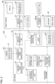
- FIG. 8 A first example of a process executed by the NC device 10 will be described using a flowchart shown in FIG. 8 .
- the processing controller 12 determines whether or not the processing program has been read into the NC device 10 in step S1. If the processing program has not been read into the NC device 10 (NO), the processing controller 12 repeats the process of step S1. If the processing program has been read into the NC device 10 (YES), the bending data extraction unit 13 extracts the shape information about the workpiece W, the position information about the workpiece W, the bending line information, the abutment identification information, the abutment coordinates, and the abutting area information for each bending process, from the processing program in step S2.
- step S3 the additional image generation unit 16 generates additional images for the first bending process.
- step S4 the superimposed image generation unit 17 generates a superimposed image obtained by superimposing the additional images on an image captured by the camera 20.
- the wireless communication unit 18 transmits the superimposed image to the tablet device 30 in step 5 and then causes the process to transition to step S7.
- the processing controller 12 (the back gauge controller 122) causes the abutments 42 to move to abutment coordinates for the first bending process in step S6 and then causes the process to transition to step S7.
- the press brake 100 transitions to a processing preparation state, though it is not shown in FIG. 8 .
- the processing controller 12 executes step S6 in the processing preparation state.
- step S7 the processing controller 12 determines whether or not a processing instruction by the close foot switch 81 has been made. If a processing instruction has not been made (NO), the processing controller 12 repeats the process of step S7. If a processing instruction has been made (YES), the processing controller 12 (the slide controller 121) causes the upper table 1 to be lowered to perform bending of the workpiece W in step S8 and then causes the process to transition to step S9. In step S9, the processing controller 12 determines whether or not there is a next bending process. If there is not a next bending process (NO), the processing controller 12 causes the process to end.
- step S9 If there is a next bending process in step S9 (YES), the additional image generation unit 16 generates additional images for the next bending process in step S10 and then causes the process to transition to step S4.
- the processing controller 12 the back gauge controller 122 causes the abutments 42 to move to abutment coordinates for the next bending process in step S11 and then causes the process to transition to step S7.
- the wireless communication unit 18 has transmitted a superimposed image to the tablet device 30 in each of all the bending processes, and the processing controller 12 performed bending of the workpiece W in each of all the bending processes, the NC device 10 causes the series of processes to end.
- FIG. 9 A second example of the process executed by the NC device 10 will be described using a flowchart shown in FIG. 9 .
- the additional image generation unit 16 generates additional images for each bending process.
- the additional image generation unit 16 generates additional images for all the bending processes in advance.
- the processing controller 12 determines whether or not the processing program has been read into the NC device 10 in step S21. If the processing program has not been read into the NC device 10 (NO), the processing controller 12 repeats the process of step S21. If the processing program has been read into the NC device 10 (YES), the bending data extraction unit 13 extracts the shape information about the workpiece W, the position information about the workpiece W, the bending line information, the abutment identification information, the abutment coordinates, and the abutting area information for each bending process, from the processing program in step S22.
- step S23 the additional image generation unit 16 generates additional images for all the bending processes.
- step S24 the NC device 10 determines whether or not operation of the press brake 100 has been started by operating the operation unit 72. If operation of the press brake 100 has not been started (NO), the NC device 10 repeats the process of step S24. If operation of the press brake 100 has been started (YES), the superimposed image generation unit 17 generates a superimposed image obtained by superimposing the additional images for the current bending process on an image captured by the camera 20 in step S25.
- the current bending process is each of the first bending process, the second bending process, the third bending process, ....
- the wireless communication unit 18 transmits the superimposed image to the tablet device 30 in step 26 and then causes the process to transition to step S28.
- the processing controller 12 causes the abutments 42 to move to abutment coordinates for the current bending process in step S27 and then causes the process to transition to step S28.
- step S28 the processing controller 12 determines whether or not a processing instruction by the close foot switch 81 has been made. If a processing instruction has not been made (NO), the processing controller 12 repeats the process of step S28. If a processing instruction has been made (YES), the processing controller 12 (the slide controller 121) causes the upper table 1 to be lowered to perform bending of the workpiece W in step S29, and then causes the process to transition to step S30.
- step S30 the processing controller 12 determines whether or not there is a next bending process. If there is a next bending process (YES), the processing controller 12 causes the process to transition to the next bending process in step S31 and returns the process to steps S25 and S27, and the processes of steps S25 to S30 are repeated. If there is not a next bending process (NO), the NC device 10 causes the series of processes to end.
- FIG. 10 shows a more preferred configuration of the NC device 10.
- the same parts as those of FIG. 2 are given the same reference signs in FIG. 10 , and description thereof will be omitted.
- the abutment 42 includes sensors 43 that detect contact of the workpiece W.
- the abutment 42 of the first example shown in FIG. 4A includes three sensors 43 in the distal end surface. Outputs from the sensors 43 are supplied to the additional image generation unit 16. It is preferable that the additional image generation unit 16 causes a display state of a abutting area image like the abutting area images 420i of FIG. 6 or 7 to be different between a state of the sensors 43 not having detected contact of the workpiece W and a state of the sensor 43 having detected contact of the workpiece W.
- the display state refers to the line color, line type, or line thickness of the abutting area image, for example.
- the operator can recognize whether or not the workpiece W has made contact with the abutment 42 based on the display state of the abutting area image.
- the additional image generation unit 16 causes the color of the abutting area image to be different between the state of the sensor 43 not having detected contact of the workpiece W and the state of the sensor 43 having detected contact of the workpiece W.
- the additional image generation unit 16 causes the abutting area image to be red.
- the additional image generation unit 16 causes the abutting area image to be blue. The operator can easily recognize whether or not the workpiece W has made contact with the abutment 42 according to the color of the abutting area image.
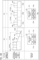
- the enlarged image 172 between the parallel images 170 shown in FIG. 6 it is preferable to cause the enlarged image 172 to be different based on the number of abutments 42 defining the position of the workpiece W in the depth direction.
- a pattern Pt1 shown in FIG. 12A shows a case in which the number of abutments 42 is one, and the workpiece W is caused to contact a single abutment 42.
- the superimposed image generation unit 17 generates one enlarged image 174 obtained by enlarging an area Ar1 represented by a one-dot chain line in a wide-range image 173.
- the wide-range image 173 is an image corresponding to the wide-range image 171 between the parallel images 170 shown in FIG. 6 .
- FIGS. 12A and 12B show examples of a way of generating an enlarged image in the case of causing the workpiece W to contact one, two, or three abutments 42.
- a pattern Pt2 shown in FIG. 12A shows a case in which the number of abutments 42 is two, the workpiece W is caused to contact the abutments 42a and 42b, and a distance D in the left/right direction between the abutments 42a and 42b is within a predetermined threshold Dth.
- the superimposed image generation unit 17 generates one enlarged image 175 obtained by enlarging an area Ar2 represented by a one-dot chain line in a wide-range image 173.
- a pattern Pt3 shown in FIG. 12A shows a case in which the number of abutments 42 is two, the workpiece W is caused to contact the abutments 42a and 42b, and the distance D in the left/right direction between the abutments 42a and 42b exceeds the threshold Dth.
- the superimposed image generation unit 17 generates a left enlarged image 176a obtained by enlarging an area Ar3a in the wide-range image 173 represented by a one-dot chain line and including the abutment 42a, and a right enlarged image 176b obtained by enlarging an area Ar3b represented by a one-dot chain line and including the abutment 42b.
- the superimposed image generation unit 17 arranges the left enlarged image 176a and the right enlarged image 176b on the left and right, side by side.
- a pattern Pt4 shown in FIG. 12B shows a case in which the number of abutments 42 is three, and the workpiece W is caused to contact the abutments 42a to 42c.
- the pattern Pt4 shows a case in which the distance D in the left/right direction between the abutments 42a and 42b is within the threshold Dth, and the distance D in the left/right direction between the abutments 42b and 42c exceeds the threshold Dth.
- the superimposed image generation unit 17 generates a left enlarged image 177a obtained by enlarging an area Ar4a in the wide-range image 173 represented by a one-dot chain line and including the abutments 42a and 42b, and a right enlarged image 177b obtained by enlarging an area Ar4b represented by a one-dot chain line and including the abutment 42c.
- the superimposed image generation unit 17 arranges the left enlarged image 177a and the right enlarged image 177b on the left and right, side by side.
- a pattern Pt5 shown in FIG. 12B shows a case in which the number of abutments 42 is three, and the workpiece W is caused to contact the abutments 42a to 42c.
- the pattern Pt5 shows a case in which both of the distance D in the left/right direction between the abutments 42a and 42b and the distance D in the left/right direction between the abutments 42b and 42c exceed the threshold Dth.
- the superimposed image generation unit 17 generates a left enlarged image 178a obtained by enlarging an area Ar5a in the wide-range image 173 represented by a one-dot chain line and including the abutment 42a, a central enlarged image 178b obtained by enlarging an area Ar5b represented by a one-dot chain line and including the abutment 42b, and a right enlarged image 178c obtained by enlarging an area Ar5c represented by a one-dot chain line and including the abutment 42c.
- the superimposed image generation unit 17 arranges the left enlarged image 178a, the central enlarged image 178b, and the right enlarged image 178c in the left/right direction.
- the superimposed image generation unit 17 generates one enlarged image such that the two abutments 42 are included therein. If the distance D in the left/right direction between two abutments 42 adjacent to each other exceeds the threshold Dth, the superimposed image generation unit 17 generates individual enlarged images such that the two abutments 42 are included in the separate enlarged images.
- FIGS. 12A and 12B on each of the enlarged images 174 and 175, the left enlarged images 176a, 177a, and 178a, the right enlarged images 176b, 177b, and 178c, and the central enlarged image 178b, at least the workpiece shape image, the bending line image, and the abutting area image are superimposed similarly to FIG. 6 .
- the enlarged images 174 and 175, the left enlarged images 176a, 177a, and 178a, the right enlarged images 176b, 177b, and 178c, and the central enlarged image 178b shown in FIGS. 12A and 12B are similarly used.
- the enlarged image display methods shown in FIGS. 12A and 12B are useful display methods when the operator confirms an enlarged image no matter whether or not a workpiece shape image, a bending line image, an abutting area image, and the like are imposed on the enlarged image. Further, the enlarged image display methods shown in FIGS. 12A and 12B are also useful display methods in the case of displaying not the parallel images 170 including the wide-range image 173 but only an enlarged image alone.
- One or more embodiments disclose a press brake shown below in addition to the press brake according to the claims.
- a press brake including:
- the present invention is not limited to one or more embodiments described above, and various changes can be made within a range not departing from the scope of the present invention.
- the display device for displaying the parallel images 170 as shown in FIG. 6 or the alternate images as shown in FIG. 7 is not limited to the tablet device 30 but may be a projector. In the case of adopting a projector as the display device, the projector can project an image on the surface of the upper table 1.
- the NC device 10 may determine that setup is underway when the workpiece W is moving, based on an image captured by the camera 20 and prevent the upper table 1 from sliding.
- the NC device 10 may warn the operator when it detects that the positions of the punch Tp and the die Td are different from the tool layout, based on an image captured by the camera 20.
- the NC device 10 may warn the operator when it detects that a bending line of the workpiece W along which the operator tries to bend the workpiece W and a bending line targeted by bending according to the processing program then are different, based on an image captured by the camera 20.
Landscapes
- Engineering & Computer Science (AREA)
- Mechanical Engineering (AREA)
- Physics & Mathematics (AREA)
- General Physics & Mathematics (AREA)
- Theoretical Computer Science (AREA)
- Quality & Reliability (AREA)
- Computer Vision & Pattern Recognition (AREA)
- Automation & Control Theory (AREA)
- Optics & Photonics (AREA)
- Bending Of Plates, Rods, And Pipes (AREA)
Abstract
Description
- The present disclosure relates to a press brake, a press brake control device, and a press brake control method.
-
Patent Literature 1 describes that a camera is arranged at least above on the far side of an upper table of a press brake and an image as a work guide showing the position or movement of an abutment of a back gauge is superimposed on an image captured by the camera. - [Patent Literature 1]
International Publication No. WO2020/041807 - In the press brake described in
Patent Literature 1, an operator cannot visually recognize at which position of the abutment the operator should cause the workpiece to abut against the abutment, in each bending process of the workpiece. - A first aspect of one or more embodiments provides a press brake including: an upper table to be fitted with a punch; a lower table to be fitted with a die; an NC device configured to control bending of a workpiece by the punch and the die based on a processing program; a back gauge arranged on a back side of the lower table and comprising one or more abutments defining a position in a depth direction at a time of placing the workpiece on the die; a camera arranged on a back side of the upper table and configured to capture an image in a direction of the lower table; and a display device configured to display the image captured by the camera; wherein the NC device includes: an additional image generation unit configured to generate, based on shape information about the workpiece, position information about a position to place the workpiece in each of bending processes of the workpiece, abutment identification information identifying an abutment to be used in each of the bending processes, abutment coordinates in real space to position the abutment in each of the bending processes, and abutting area information indicating an area of the abutments to be abutted by the workpiece in each of the bending processes extracted from the processing program, and coordinate conversion values for converting a position in the real space the camera captures an image of to a position on the captured image, an additional image to be added to the captured image, including a workpiece shape image showing a shape of the workpiece and an abutting area image showing the areas of the abutment to be abutted by the workpiece; and a superimposed image generation unit configured to generate a superimposed image to be displayed on the display device by superimposing the additional image on the captured image.
- According to the first aspect of one or more embodiments, it is possible to display a superimposed image obtained by superimposing a workpiece shape image and an abutting area image on an image captured by a camera, on a display device. Therefore, an operator can visually recognize at which position of an abutment the operator should cause the workpiece to abut against the abutment.
- A second aspect of one or more embodiments provides a press brake control device including: a bending data extraction unit configured to extract, from a processing program for performing bending of a workpiece to be processed, shape information about the workpiece, position information about a position to place the workpiece in each of bending processes of the workpiece, abutment identification information identifying an abutment to be used in each of the bending processes, abutment coordinates in real space to position the abutment in each of the bending processes, and abutting area information indicating an area of the abutment to be abutted by the workpiece in each of the bending processes as bending data; an additional image generation unit configured to generate, based on the shape information about the workpiece, the position information about the workpiece, the abutment identification information, the abutment coordinates, and the abutting area information extracted by the bending data extraction unit, and coordinate conversion values for converting a position in real space in a direction of a lower table a camera captures an image of to a position on the image captured by the camera, the camera being placed on a backside of an upper table, and the coordinate conversion values being determined in advance and held in a holding unit, an additional image including a workpiece shape image showing a shape of the workpiece and an abutting area image showing the areas of the abutment to be abutted by the workpiece; and a superimposed image generation unit configured to generate a superimposed image obtained by superimposing the additional image on the captured image to generate a superimposed image to be displayed on a display device.
- According to the second aspect of one or more embodiments, it is possible to perform control to display a superimposed image obtained by superimposing a workpiece shape image and an abutting area image on an image captured by a camera, on a display device. Therefore, the operator can visually recognize at which position of the abutment the operator should cause the workpiece to abut against the abutment.
- A third aspect of one or more embodiments provides a press brake control method including: extracting from a processing program for performing, by an NC device configured to control bending of the workpiece, bending of a workpiece to be processed, shape information about the workpiece, position information about a position to place the workpiece in each of bending processes of the workpiece, abutment identification information identifying an abutment to be used in each of the bending processes, abutment coordinates in real space to position the abutment in each of the bending processes, and abutting area information indicating an area of the abutment to be abutted by the workpiece in each of the bending processes; generating, by the NC device, an additional image including a workpiece shape image showing a shape of the workpiece and an abutting area image showing the area of the abutment to be abutted by the workpiece, based on the shape information about the workpiece, the position information about the workpiece, the abutment identification information, the abutment coordinates, and the abutting area information, and coordinate conversion values for converting a position in real space in a direction of a lower table a camera captures an image of to a position on the image captured by the camera, the camera being placed on a backside of an upper table, and the coordinate conversion values being determined in advance and held in a holding unit; and generating, by the NC device, a superimposed image obtained by superimposing the additional images on the captured image to generate a superimposed image to be displayed on a display device.
- According to the third aspect of one or more embodiments, it is possible to perform control to display a superimposed image obtained by superimposing a workpiece shape image and an abutting area image on an image captured by a camera, on a display device. Therefore, the operator can visually recognize at which position of the abutment the operator should cause the workpiece to abut against the abutment.
- According to the press brake, the press brake control device, and the press brake control method according to one or more embodiments, it is possible for the operator to perform bending of a workpiece while visually recognizing at which position of the abutment the operator should cause the workpiece to abut against the abutment in each bending process of the workpiece.
-
- [
FIG. 1] FIG. 1 is a diagram illustrating an overall configuration of a press brake according to one or more embodiments. - [
FIG. 2] FIG. 2 is a block diagram illustrating the press brake according to one or more embodiments. - [
FIG. 3] FIG. 3 is a plan view illustrating an example of a shape of a workpiece that is bent by the press brake according to one or more embodiments. - [
FIG. 4A] FIG. 4A is a partial plan view illustrating a first example of the shape of an abutment of a back gauge included in the press brake according to one or more embodiments. - [
FIG. 4B] FIG. 4B is a partial plan view illustrating a second example of the shape of an abutment of the back gauge included in the press brake according to one or more embodiments. - [
FIG. 5A] FIG. 5A is a partial plan view illustrating an abutting area to be abutted by the workpiece when the abutment of the first example shown inFIG. 4A is used. - [
FIG. 5B] FIG. 5B is a partial plan view illustrating an abutting area to be abutted by the workpiece when the abutment of the second example shown inFIG. 4B is used. - [
FIG. 6] FIG. 6 is a diagram illustrating an example of parallel images generated and transmitted to a tablet device by an NC device of the press brake according to one or more embodiments. - [
FIG. 7] FIG. 7 is a diagram illustrating an example of alternate images generated and transmitted to the tablet device by the NC device of the press brake according to one or more embodiments. - [
FIG. 8] FIG. 8 is a flowchart illustrating a first example of processes executed by the press brake according to one or more embodiments. - [
FIG. 9] FIG. 9 is a flowchart illustrating a second example of the processes executed by the press brake according to one or more embodiments. - [
FIG. 10] FIG. 10 is a block diagram illustrating a preferred configuration of the press brake according to one or more embodiments. - [
FIG. 11] FIG. 11 is a partial perspective view illustrating an example of sensors included in the abutment. - [
FIG. 12A] FIG. 12A is a diagram illustrating an example of a way of generating an enlarged image in the case of causing the workpiece to make contact with one or two abutments. - [
FIG. 12B] FIG. 12B is a diagram illustrating an example of a way of generating an enlarged image in the case of causing the workpiece to make contact with three abutments. - A press brake according to one or more embodiments includes: an upper table to be fitted with a punch; a lower table to be fitted with a die; an NC device configured to control bending of a workpiece by the punch and the die based on a processing program; a back gauge arranged on a back side of the lower table and comprising one or more abutments defining a position in a depth direction at a time of placing the workpiece on the die; a camera arranged on a back side of the upper table and configured to capture an image in a direction of the lower table; and a display device configured to display the image captured by the camera.
- The NC device includes an additional image generation unit and a superimposed image generation unit. The additional image generation unit generates, based on shape information about the workpiece, position information about a position to place the workpiece in each of bending processes of the workpiece, abutment identification information identifying abutments to be used in each of the bending processes, abutment coordinates in real space to position the abutments in each of the bending processes, and abutting area information indicating areas of the abutments to be abutted by the workpiece in each of the bending processes extracted from the processing program, and coordinate conversion values for converting a position in the real space the camera captures an image of to a position on the captured image, additional images to be added to the captured image, including a workpiece shape image showing a shape of the workpiece and abutting area images showing the areas of the abutments to be abutted by the workpiece.
- The superimposed image generation unit generates a superimposed image to be displayed on the display device by superimposing the additional images on the captured image.
- A press brake control device according to one or more embodiments includes a bending data extraction unit, an additional image generation unit, and a superimposed image generation unit. The bending data extraction unit extracts, from a processing program for performing bending of a workpiece to be processed, shape information about the workpiece, position information about a position to place the workpiece in each of bending processes of the workpiece, abutment identification information identifying abutments to be used in each of the bending processes, abutment coordinates in real space to position the abutments in each of the bending processes, and abutting area information indicating areas of the abutments to be abutted by the workpiece in each of the bending processes as bending data.
- The additional image generation unit generates, based on the shape information about the workpiece, the position information about the workpiece, the abutment identification information, the abutment coordinates, and the abutting area information extracted by the bending data extraction unit, and coordinate conversion values for converting a position in real space in a direction of a lower table a camera captures an image of to a position on the image captured by the camera, the camera being placed on a backside of an upper table, and the coordinate conversion values being determined in advance and held in a holding unit, additional images including a workpiece shape image showing a shape of the workpiece and abutting area images showing the areas of the abutments to be abutted by the workpiece.
- The superimposed image generation unit generate a superimposed image obtained by superimposing the additional images on the captured image to generate a superimposed image to be displayed on a display device.
- In a press brake control method according to one or more embodiments, an NC device configured to control bending of the workpiece extracts, from a processing program for performing bending of a workpiece to be processed, shape information about the workpiece, position information about a position to place the workpiece in each of bending processes of the workpiece, abutment identification information identifying abutments to be used in each of the bending processes, abutment coordinates in real space to position the abutments in each of the bending processes, and abutting area information indicating areas of the abutments to be abutted by the workpiece in each of the bending processes.
- The NC device generates, based on the shape information about the workpiece, the position information about the workpiece, the abutment identification information, the abutment coordinates, and the abutting area information, and coordinate conversion values for converting a position in real space in a direction of a lower table a camera captures an image of to a position on the image captured by the camera, the camera being placed on a backside of an upper table, and the coordinate conversion values being determined in advance and held in a holding unit, additional images including a workpiece shape image showing a shape of the workpiece and a abutting area image showing the areas of the abutments to be abutted by the workpiece.
- The NC device generates a superimposed image obtained by superimposing the additional images on the captured image to generate a superimposed image to be displayed on a display device.
- The press brake, the press brake control device, and the press brake control method according to one or more embodiments will be described below in detail with reference to accompanying drawings.
-
FIG. 1 shows an overall configuration of apress brake 100 according to one or more embodiments. As shown inFIG. 1 , thepress brake 100 includes a numerical control (NC)device 10 that functions as a press brake control device. To the NCdevice 10, aprocessing program database 50 is connected via a network. Thepress brake 100 includes an upper table 1, a lower table 3, and right andleft side panels upper tool holder 2 is attached to the upper table 1, and alower tool holder 4 is attached to the lower table 3. The upper table 1 is configured to be vertically moved byhydraulic cylinders - A punch Tp, which is an upper tool, is fitted to the
upper tool holder 2, and a die Td, which is a lower tool, is fitted to thelower tool holder 4. Though a modular type in which theupper tool holder 2 is integrally attached to the entire length of the lower end of the upper table 1 is shown inFIG. 1 , an intermediate plate type in which a plurality of intermediate plates to be fitted with the punch Tp are attached in a longitudinal direction of the lower end of the upper table 1 may be adopted. The intermediate plates are also upper tool holders. - To fit the punch Tp to the upper table 1 means to fit the punch Tp to the
upper tool holder 2 or the intermediate plates. To fit the die Td to the lower table 3 means to fit the die Td to thelower tool holder 4. Two or more punches Tp may be fitted to the upper table 1 side by side, and two or more dies Td may be fitted to the lower table 3 side by side. - A
back gauge 40 is arranged on the back side of the lower table 3. Theback gauge 40 is provided withabutments back gauge carriage 41. Though it is assumed here that the twoabutments abutment 42. Theabutment 42 is configured to move both in the height direction and in the forward/backward direction. - Before an operator places a workpiece W, which is a sheet metal to be processed, on the die Td and bends the workpiece W, the
abutment 42 moves to a position corresponding to the die Td. The operator places the workpiece W on the die Td in a manner of causing the end of the workpiece W on the far side to abut theabutment 42. That is, theabutment 42 acts to define the position of workpiece W in the forward/backward direction at the time of placing the workpiece W on the die Td. - On the left side of the
press brake 100, anoperation pendant 7, which includes adisplay 71 and anoperation unit 72 with a plurality of operation buttons, is attached via anarm 7a. Theoperation pendant 7 is connected to theNC device 10. Afoot switch 8, which includes aclose foot switch 81 for lowering the upper table 1 and anopen foot switch 82 for raising the upper table 1, is connected to theNC device 10. - The right and
left side panels coupling bar 51. Thecoupling bar 51 is located behind the upper table 1 and at upper parts of the right andleft side panels camera 20 is fitted to the lower surface of thecoupling bar 51, in the center of the left/right direction of thecoupling bar 51. Thecamera 20 is arranged on the back side of the upper table 1 to capture an image in the direction of the lower table 3. It is preferred that thecamera 20 includes a fisheye lens so as to be capable of capturing an image from the right-side end to left-side end of the lower table 3. It is preferable that thecamera 20 includes a fisheye lens, since this allows for capturing images of a wide range. - The
camera 20 may include a wide-angle lens or an ultra-wide-angle lens instead of the fisheye lens if it is possible to capture an image from the right-side end to left-side end of the lower table 3. An image captured by thecamera 20 is supplied to theNC device 10. - A
tablet device 30, which is an example of the display device, is fitted to the surface of the upper table 1. It is preferable that thetablet device 30 is attachable to and detachable from the upper table 1. On the upper table 1, afitting portion 301 for thetablet device 30 extending in the left/right direction is formed. It is preferable that thetablet device 30 is configured such that the fitting position relative to the upper table 1 in the left/right direction can be changed along thefitting portion 301. Thefitting portion 301 may be configured such that thetablet device 30 can be fitted into a recess portion thereof, for example, or may be configured such that thetablet device 30 can be fitted to thefitting portion 301 with a magnet, for example. The configuration for fitting thetablet device 30 to the upper table 1 and the configuration for causing thetablet device 30 to be movable in the left/right direction are not limited. - The
tablet device 30 is connected to theNC device 10. As an example, theNC device 10 and thetablet device 30 are connected via a wireless LAN. Typically, Wi-Fi, which is a wireless LAN in conformity with the communication standard IEEE 802.11, can be used. TheNC device 10 and thetablet device 30 may be connected via Bluetooth (registered trademark) which is an example of near field wireless communication standards. It is preferable that theNC device 10 and thetablet device 30 are connected to each other via wireless communication, since it is easy to move thetablet device 30, and it is also possible to remove thetablet device 30 from thefitting portion 301 for use. TheNC device 10 and thetablet device 30, however, may be connected by wire. -
FIG. 2 is a block diagram showing thepress brake 100 according to one or more embodiments. Operation of thepress brake 100 will be described usingFIG. 2 . TheNC device 10 includes a processingprogram holding unit 11, aprocessing controller 12, a bendingdata extraction unit 13, a bendingdata holding unit 14, a coordinate conversionvalue holding unit 15, an additionalimage generation unit 16, a superimposedimage generation unit 17, and awireless communication unit 18. Theprocessing controller 12 includes aslide controller 121 that controls thehydraulic cylinders back gauge controller 122 that controls theback gauge 40. Thecamera 20 includes afisheye lens 21. Thetablet device 30 includes awireless communication unit 31, animage display controller 32, and adisplay 33. Thewireless communication units - The processing
program holding unit 11, the bendingdata holding unit 14, and the coordinate conversionvalue holding unit 15 can be constituted of a storage unit included in theNC device 10. Theprocessing controller 12, the bendingdata extraction unit 13, the additionalimage generation unit 16, and the superimposedimage generation unit 17 can be functionally formed by a central processing unit included in theNC device 10 executing software. Thewireless communication unit 18 can be constituted of a circuit that executes wireless communication and an antenna. Thewireless communication unit 31 can be constituted of a circuit that executes wireless communication and an antenna. Theimage display controller 32 can be functionally formed by a central processing unit included in thetablet device 30 executing software. Thedisplay 33 is a liquid crystal panel, for example. - At the time of trying to process the workpiece W, the processing
program holding unit 11 holds a processing program read by theNC device 10 from theprocessing program database 50. When the processing program is held in the processingprogram holding unit 11, and theprocessing controller 12 is instructed to start processing of the workpiece W, theprocessing controller 12 controls processing of the workpiece W according to the processing program. Theback gauge controller 122 controls theback gauge 40 to move theabutment 42 according to the processing program. Theslide controller 121 controls thehydraulic cylinders foot switch 8. - When the processing program is held in the processing
program holding unit 11, the bendingdata extraction unit 13 extracts bending data shown below from the processing program. - The bending data extracted from the processing program includes shape information about the workpiece W, position information about a position to place the workpiece W in each bending process of the workpiece W, and bending line information showing a position of bending of the workpiece W in each process.
FIG. 3 shows an example of the shape of the workpiece W to be bent by thepress brake 100. When the workpiece W shown inFIG. 3 is exemplified, the shape information about the workpiece W is represented by coordinate values identifying the shape of the workpiece W. The position information about the workpiece W is position information indicating where on the lower table 3 in the left/right direction and in the depth direction the workpiece W is to be placed. The position information about the workpiece W can be obtained from a three-dimensional model in the processing program. The workpiece W shown inFIG. 3 includes bending lines V1 to V4, and the bending data includes bending line information indicating the bending lines V1 to V4. The bending data includes bending order information indicating bending order of the bending lines V1 to V4. - In addition, the bending data includes abutment identification information identifying the
abutment 42 to be used in each bending process, abutment coordinates in real space where theabutment 42 is to be positioned in each bending process, and abutting area information indicating an area of theabutment 42 to be abutted by the workpiece W in each bending process. The abutment identification information is represented by a number identifying each ofabutments 42 in various shapes.FIGS. 4A and 4B show first and second examples of the shape of theabutment 42, respectively. - The
abutment 42 of the first example shown inFIG. 4A is in a plate shape with a rectangular end on the distal end side. Theabutment 42 of the second example shown inFIG. 4B includes alower portion 421 and anupper portion 422, and semicircular recess portions are formed on thelower portion 421 and theupper portion 422. Which shape ofabutment 42 is to be used is identified by the abutment identification information. - The abutment coordinates indicate where on the lower table 3 in the left/right direction and in the depth direction the
abutment 42 is to be arranged.FIGS. 5A and 5B show abutting areas to be butted by the workpiece W when theabutments 42 of the first and second examples shown inFIGS. 4A and 4B are used, respectively. As indicated by a thick solid line inFIG. 5A , the abutting area of theabutment 42 shown inFIG. 4A is adistal end surface 420 of theabutment 42, and the abutting area information is information indicating the position of thedistal end surface 420 of theabutment 42. As indicated by a thick solid line inFIG. 5B , the abutting area of theabutment 42 shown inFIG. 4B is adistal end surface 4220 of theupper portion 422, for example, and the abutting area information is information indicating the position of thedistal end surface 4220 of theupper portion 422. - Returning to
FIG. 2 , the bendingdata holding unit 14 holds the bending data extracted by the bendingdata extraction unit 13. The coordinate conversionvalue holding unit 15 holds the coordinate conversion values for converting a position in real space thecamera 20 captures an image of to a position on the image captured by thecamera 20. The coordinate conversion values can be constituted of a set of two-dimensional conversion values for converting two-dimensional coordinates in real space thecamera 20 captures an image of to two-dimensional coordinates on the image captured by thecamera 20. - The additional
image generation unit 16 generates additional images to be added to the image captured by thecamera 20 based on the bending data held in the bendingdata holding unit 14 and the coordinate conversion values held in the coordinate conversionvalue holding unit 15. In order to generate the additional images, the additionalimage generation unit 16 uses the shape information about the workpiece W, and the position information about the position to place the workpiece W, the bending line information about the workpiece W, the abutment identification information, the abutment coordinates, and the abutting area information for each bending process. The additionalimage generation unit 16 generates the additional images for each bending process. - The additional
image generation unit 16 holds coordinate values identifying the shape ofabutment 42 for each piece of abutment identification information. Therefore, the additionalimage generation unit 16 can generate an abutment image to be described later, based on the abutment identification information. - The captured image outputted from the
camera 20 and the additional images from the additionalimage generation unit 16 are supplied to the superimposedimage generation unit 17. Since thecamera 20 includes thefisheye lens 21, the image captured by thecamera 20 is a distorted image with an angle of view of 180 degrees. Thecamera 20, however, is configured to output the captured image in a state of the distortion being corrected in order to reduce visually uncomfortable feeling. Therefore, the captured image supplied to the superimposedimage generation unit 17 is an image that does not give visually uncomfortable feeling almost at all. - The superimposed
image generation unit 17 generates a superimposed image obtained by superimposing the additional images on the captured image.FIG. 6 shows an example of parallel images generated and transmitted to thetablet device 30 by theNC device 10. As shown inFIG. 6 , it is preferable that the superimposedimage generation unit 17 generatesparallel images 170, including a wide-range image 171 based on the angle of view of thecamera 20 and anenlarged image 172, which is an enlarged partial area of the wide-range image 171, arranged vertically, for example. It is preferable that the wide-range image 171 corresponds to the entire angle of view of thecamera 20. The wide-range image 171 includes the lower table 3, the right andleft side panels back gauge 40, and the whole of adoor 52 at the rear which is not shown inFIG. 1 . A workpiece shape image Wi based on the shape information about the workpiece W is superimposed on the wide-range image 171. - The
enlarged image 172 includes the entire die Td, parts of the lower table 3 and theabutments enlarged image 172, the workpiece shape image Wi, a bending line image V1i,abutment images 42i, and abuttingarea images 420i are superimposed. Eachabutment image 42i here shows the shape of a distal-end side end of theabutment 42. - It is not indispensable to superimpose all of the workpiece shape image Wi, the bending line image V1i, the
abutment images 42i, and the abuttingarea images 420i on theenlarged image 172, and it is only required to superimpose at least the workpiece shape image Wi and the abuttingarea images 420i on theenlarged image 172. If the workpiece shape image Wi and the abuttingarea images 420i are superimposed on theenlarged image 172, it becomes possible for the operator to perform bending of the workpiece W while visually recognizing at which positions of theabutments 42 the operator should cause the workpiece W to abut against theabutments 42. - It is preferable to superimpose the bending line image V1i on the
enlarged image 172, in addition to the workpiece shape image Wi and the abuttingarea images 420i. If the workpiece shape image Wi and the abuttingarea images 420i are superimposed on theenlarged image 172, it becomes possible for the operator to perform bending of the workpiece W while visually recognizing at which position the workpiece W should be bent and at which positions of theabutments 42 the operator should cause the workpiece W to abut against theabutments 42. - It is further preferable to superimpose the bending line image V1i and the
abutment images 42i on theenlarged image 172, in addition to the workpiece shape image Wi and the abuttingarea images 420i. If theabutment images 42i are superimposed on theenlarged image 172, it becomes easy for the operator to recognize the positions of theabutments 42. When both theabutment images 42i and the abuttingarea images 420i are superimposed on theenlarged image 172, it is preferable to make the both images have different colors. - Though only the workpiece shape image Wi is superimposed on the wide-
range image 171 in the parallel images shown inFIG. 6 , the abuttingarea images 420i may also be superimposed. The bending line image V1i may also be superimposed on the wide-range image 171 in addition to the workpiece shape image Wi and the abuttingarea images 420i. The bending line image V1i and theabutment images 42i may also be superimposed on the wide-range image 171 in addition to the workpiece shape image Wi and the abuttingarea images 420i. - In the case of superimposing only the workpiece shape image Wi and the abutting
area images 420i on the enlarged image 172 (or the wide-range image 171), the bendingdata extraction unit 13 can extract the shape information about the workpiece W, the position information about the position to place the workpiece W, the abutment identification information, the abutment coordinates, and the abutting area information from the processing program. - The
wireless communication unit 18 wirelessly transmits theparallel images 170 shown inFIG. 6 to thewireless communication unit 31 of thetablet device 30. Thewireless communication unit 31 receives theparallel images 170 and supplies them to theimage display controller 32. Theimage display controller 32 supplies theparallel images 170 to thedisplay 33 and controls thedisplay 33 to display theparallel images 170 on thedisplay 33. - Since the
parallel images 170 shown inFIG. 6 are displayed on thetablet device 30 fitted to the surface of the upper table 1, the operator can confirm the wide-range image 171 and theenlarged image 172 and perform bending of the workpiece W while visually recognizing at which position the workpiece W is to be bent and at which positions of theabutments 42 the operator should cause the workpiece W to abut against theabutments 42. At this time, thetablet device 30 is located almost directly in front of the operator. Therefore, the operator does not need to move to the side or turn his or her face to the side as he or she does at the time of confirming information displayed on thedisplay 71 of theoperation pendant 7. - Especially, when there are a plurality of areas to be abutted by the workpiece W like the
abutment 42 of the second example shown inFIG. 4B , it is possible to, by a abutting area image being superimposed on theenlarged image 172, prevent the operator from recognizing a wrong position as the area to be abutted by the workpiece W. When theabutment 42 of the second example is used, and thedistal end surface 4220 of theupper portion 422 is the area to be abutted, a abutting area image is superimposed at the position of thedistal end surface 4220. -
FIG. 7 shows an example of alternative images generated and transmitted to thetablet device 30 by theNC device 10. As shown inFIG. 7 , instead of theparallel images 170 shown inFIG. 6 , the superimposedimage generation unit 17 may alternately generate the wide-range image 171 and theenlarged image 172, and thewireless communication unit 18 may alternately transmit the wide-range image 171 and theenlarged image 172 to thewireless communication unit 31. The superimposedimage generation unit 17 switches between the wide-range image 171 and theenlarged image 172 at predetermined intervals of two or three seconds, for example. On thedisplay 33 of thetablet device 30, the alternate images, which are the wide-range image 171 and theenlarged image 172 switched at the predetermined intervals, are displayed. Similarly to the case of theparallel images 170 being displayed on thetablet device 30, the operator can confirm the wide-range image 171 and theenlarged image 172 and perform bending of the workpiece W while visually recognizing a position to bend the workpiece W and positions to be abutted by the workpiece W against theabutments 42. - When the workpiece W shown in
FIG. 3 is a processing target, the superimposedimage generation unit 17 generates parallel images or alternate images similar to those ofFIG. 6 or7 for each of bending processes for the bending lines V1 to V4 according to the processing program, and the parallel images or the alternate images are displayed on thetablet device 30. Therefore, the operator can perform bending of the workpiece W while visually recognizing a position to bend the workpiece W and positions to be abutted by the workpiece W against theabutments 42 in all the bending processes. - Positions on the upper table 1 and the lower table 3 where the punch Tp and the die Td are to be fitted, respectively, are set by a tool layout of the processing program, for each of the bending processes for the bending lines V1 to V4. That is, which positions of the upper table 1 and the lower table 3 in the left/right direction the bending of the workpiece W is to be performed is set by the tool layout. If, when the position of bending of the workpiece W in the left/right direction is not fixed in the center, and the position of bending is shifted in any of the left and right directions, the
tablet device 30 may be moved according to the position of bending of the workpiece W along thefitting portion 301. In this way, thetablet device 30 can be positioned almost directly in front of the operator at all times. - A first example of a process executed by the
NC device 10 will be described using a flowchart shown inFIG. 8 . InFIG. 8 , when the process of theNC device 10 is started, theprocessing controller 12 determines whether or not the processing program has been read into theNC device 10 in step S1. If the processing program has not been read into the NC device 10 (NO), theprocessing controller 12 repeats the process of step S1. If the processing program has been read into the NC device 10 (YES), the bendingdata extraction unit 13 extracts the shape information about the workpiece W, the position information about the workpiece W, the bending line information, the abutment identification information, the abutment coordinates, and the abutting area information for each bending process, from the processing program in step S2. - In step S3, the additional
image generation unit 16 generates additional images for the first bending process. In step S4, the superimposedimage generation unit 17 generates a superimposed image obtained by superimposing the additional images on an image captured by thecamera 20. Thewireless communication unit 18 transmits the superimposed image to thetablet device 30 in step 5 and then causes the process to transition to step S7. - In parallel with steps S2 to S5, the processing controller 12 (the back gauge controller 122) causes the
abutments 42 to move to abutment coordinates for the first bending process in step S6 and then causes the process to transition to step S7. By the operator executing a predetermined operation by theoperation unit 72 of theoperation pendant 7, thepress brake 100 transitions to a processing preparation state, though it is not shown inFIG. 8 . Theprocessing controller 12 executes step S6 in the processing preparation state. - In step S7, the
processing controller 12 determines whether or not a processing instruction by theclose foot switch 81 has been made. If a processing instruction has not been made (NO), theprocessing controller 12 repeats the process of step S7. If a processing instruction has been made (YES), the processing controller 12 (the slide controller 121) causes the upper table 1 to be lowered to perform bending of the workpiece W in step S8 and then causes the process to transition to step S9. In step S9, theprocessing controller 12 determines whether or not there is a next bending process. If there is not a next bending process (NO), theprocessing controller 12 causes the process to end. - If there is a next bending process in step S9 (YES), the additional
image generation unit 16 generates additional images for the next bending process in step S10 and then causes the process to transition to step S4. In parallel with steps S10, the processing controller 12 (the back gauge controller 122) causes theabutments 42 to move to abutment coordinates for the next bending process in step S11 and then causes the process to transition to step S7. - When the additional
image generation unit 16 has generated additional images in each of all the bending processes, thewireless communication unit 18 has transmitted a superimposed image to thetablet device 30 in each of all the bending processes, and theprocessing controller 12 performed bending of the workpiece W in each of all the bending processes, theNC device 10 causes the series of processes to end. - A second example of the process executed by the
NC device 10 will be described using a flowchart shown inFIG. 9 . In the first example shown inFIG. 8 , the additionalimage generation unit 16 generates additional images for each bending process. In the second example shown inFIG. 9 , the additionalimage generation unit 16 generates additional images for all the bending processes in advance. - In
FIG. 9 , when the process of theNC device 10 is started, theprocessing controller 12 determines whether or not the processing program has been read into theNC device 10 in step S21. If the processing program has not been read into the NC device 10 (NO), theprocessing controller 12 repeats the process of step S21. If the processing program has been read into the NC device 10 (YES), the bendingdata extraction unit 13 extracts the shape information about the workpiece W, the position information about the workpiece W, the bending line information, the abutment identification information, the abutment coordinates, and the abutting area information for each bending process, from the processing program in step S22. - In step S23, the additional
image generation unit 16 generates additional images for all the bending processes. In step S24, theNC device 10 determines whether or not operation of thepress brake 100 has been started by operating theoperation unit 72. If operation of thepress brake 100 has not been started (NO), theNC device 10 repeats the process of step S24. If operation of thepress brake 100 has been started (YES), the superimposedimage generation unit 17 generates a superimposed image obtained by superimposing the additional images for the current bending process on an image captured by thecamera 20 in step S25. The current bending process is each of the first bending process, the second bending process, the third bending process, .... - The
wireless communication unit 18 transmits the superimposed image to thetablet device 30 in step 26 and then causes the process to transition to step S28. - In parallel with steps S25 and S26, the processing controller 12 (the back gauge controller 122) causes the
abutments 42 to move to abutment coordinates for the current bending process in step S27 and then causes the process to transition to step S28. - In step S28, the
processing controller 12 determines whether or not a processing instruction by theclose foot switch 81 has been made. If a processing instruction has not been made (NO), theprocessing controller 12 repeats the process of step S28. If a processing instruction has been made (YES), the processing controller 12 (the slide controller 121) causes the upper table 1 to be lowered to perform bending of the workpiece W in step S29, and then causes the process to transition to step S30. - In step S30, the
processing controller 12 determines whether or not there is a next bending process. If there is a next bending process (YES), theprocessing controller 12 causes the process to transition to the next bending process in step S31 and returns the process to steps S25 and S27, and the processes of steps S25 to S30 are repeated. If there is not a next bending process (NO), theNC device 10 causes the series of processes to end. -
FIG. 10 shows a more preferred configuration of theNC device 10. The same parts as those ofFIG. 2 are given the same reference signs inFIG. 10 , and description thereof will be omitted. Theabutment 42 includessensors 43 that detect contact of the workpiece W. As shown inFIG. 11 , theabutment 42 of the first example shown inFIG. 4A includes threesensors 43 in the distal end surface. Outputs from thesensors 43 are supplied to the additionalimage generation unit 16. It is preferable that the additionalimage generation unit 16 causes a display state of a abutting area image like the abuttingarea images 420i ofFIG. 6 or7 to be different between a state of thesensors 43 not having detected contact of the workpiece W and a state of thesensor 43 having detected contact of the workpiece W. The display state refers to the line color, line type, or line thickness of the abutting area image, for example. The operator can recognize whether or not the workpiece W has made contact with theabutment 42 based on the display state of the abutting area image. - It is preferable that the additional
image generation unit 16 causes the color of the abutting area image to be different between the state of thesensor 43 not having detected contact of the workpiece W and the state of thesensor 43 having detected contact of the workpiece W. As an example, in a state in which the distal end of the workpiece W has not reached theabutment 42, and thesensors 43 have not detected contact of the workpiece W, the additionalimage generation unit 16 causes the abutting area image to be red. As an example, in a state in which the distal end of the workpiece W has reached theabutment 42, and thesensor 43 has detected contact of the workpiece W, the additionalimage generation unit 16 causes the abutting area image to be blue. The operator can easily recognize whether or not the workpiece W has made contact with theabutment 42 according to the color of the abutting area image. - As for the
enlarged image 172 between theparallel images 170 shown inFIG. 6 , it is preferable to cause theenlarged image 172 to be different based on the number ofabutments 42 defining the position of the workpiece W in the depth direction. A pattern Pt1 shown inFIG. 12A shows a case in which the number ofabutments 42 is one, and the workpiece W is caused to contact asingle abutment 42. At this time, the superimposedimage generation unit 17 generates oneenlarged image 174 obtained by enlarging an area Ar1 represented by a one-dot chain line in a wide-range image 173. The wide-range image 173 is an image corresponding to the wide-range image 171 between theparallel images 170 shown inFIG. 6 . -
FIGS. 12A and12B show examples of a way of generating an enlarged image in the case of causing the workpiece W to contact one, two, or threeabutments 42. A pattern Pt2 shown inFIG. 12A shows a case in which the number ofabutments 42 is two, the workpiece W is caused to contact theabutments abutments image generation unit 17 generates oneenlarged image 175 obtained by enlarging an area Ar2 represented by a one-dot chain line in a wide-range image 173. - A pattern Pt3 shown in
FIG. 12A shows a case in which the number ofabutments 42 is two, the workpiece W is caused to contact theabutments abutments image generation unit 17 generates a leftenlarged image 176a obtained by enlarging an area Ar3a in the wide-range image 173 represented by a one-dot chain line and including theabutment 42a, and a rightenlarged image 176b obtained by enlarging an area Ar3b represented by a one-dot chain line and including theabutment 42b. The superimposedimage generation unit 17 arranges the leftenlarged image 176a and the rightenlarged image 176b on the left and right, side by side. - A pattern Pt4 shown in
FIG. 12B shows a case in which the number ofabutments 42 is three, and the workpiece W is caused to contact theabutments 42a to 42c. The pattern Pt4 shows a case in which the distance D in the left/right direction between theabutments abutments image generation unit 17 generates a leftenlarged image 177a obtained by enlarging an area Ar4a in the wide-range image 173 represented by a one-dot chain line and including theabutments enlarged image 177b obtained by enlarging an area Ar4b represented by a one-dot chain line and including theabutment 42c. The superimposedimage generation unit 17 arranges the leftenlarged image 177a and the rightenlarged image 177b on the left and right, side by side. - A pattern Pt5 shown in
FIG. 12B shows a case in which the number ofabutments 42 is three, and the workpiece W is caused to contact theabutments 42a to 42c. The pattern Pt5 shows a case in which both of the distance D in the left/right direction between theabutments abutments image generation unit 17 generates a leftenlarged image 178a obtained by enlarging an area Ar5a in the wide-range image 173 represented by a one-dot chain line and including theabutment 42a, a centralenlarged image 178b obtained by enlarging an area Ar5b represented by a one-dot chain line and including theabutment 42b, and a rightenlarged image 178c obtained by enlarging an area Ar5c represented by a one-dot chain line and including theabutment 42c. - The superimposed
image generation unit 17 arranges the leftenlarged image 178a, the centralenlarged image 178b, and the rightenlarged image 178c in the left/right direction. - In this way, if the distance D in the left/right direction between two
abutments 42 adjacent to each other is within the threshold Dth, the superimposedimage generation unit 17 generates one enlarged image such that the twoabutments 42 are included therein. If the distance D in the left/right direction between twoabutments 42 adjacent to each other exceeds the threshold Dth, the superimposedimage generation unit 17 generates individual enlarged images such that the twoabutments 42 are included in the separate enlarged images. - In
FIGS. 12A and12B , on each of theenlarged images enlarged images enlarged images enlarged image 178b, at least the workpiece shape image, the bending line image, and the abutting area image are superimposed similarly toFIG. 6 . In the case of adopting alternate images as shown inFIG. 7 , theenlarged images enlarged images enlarged images enlarged image 178b shown inFIGS. 12A and12B are similarly used. - The enlarged image display methods shown in
FIGS. 12A and12B are useful display methods when the operator confirms an enlarged image no matter whether or not a workpiece shape image, a bending line image, an abutting area image, and the like are imposed on the enlarged image. Further, the enlarged image display methods shown inFIGS. 12A and12B are also useful display methods in the case of displaying not theparallel images 170 including the wide-range image 173 but only an enlarged image alone. - One or more embodiments disclose a press brake shown below in addition to the press brake according to the claims.
- A press brake including:
- an upper table to be fitted with a punch;
- a lower table to be fitted with a die;
- an NC device configured to control bending of a workpiece by the punch and the die;
- a back gauge arranged on a back side of the lower table and comprising one or more abutments defining a position in a depth direction at a time of placing the workpiece on the die;
- a camera arranged on a back side of the upper table and configured to capture an image in a direction of the lower table; and
- a display device configured to display the image captured by the camera; wherein
- when two or more abutments are used in the back gauge, the NC device is configured to generate, if a distance between two abutments adjacent to each other in a left/right direction is within a predetermined threshold, one enlarged image obtained by enlarging a partial area in the captured image such that the two abutments are included and to supply the enlarged image to the display device, and to generate, if the distance between the two abutments adjacent to each other in the left/right direction exceeds the threshold, individual enlarged images obtained by enlarging separate areas in the captured image such that the two abutments are included in the separate enlarged images and to supply the enlarged images to the display device.
- According to this press brake, appropriate enlarged images according to each positional relationship between two abutments adjacent to each other among the two or more abutments used in the back gauge are displayed on the display device. Therefore, the operator can sufficiently confirm whether or not a workpiece and the abutments are in an appropriate positional relationship based on the enlarged image or images.
- The present invention is not limited to one or more embodiments described above, and various changes can be made within a range not departing from the scope of the present invention. The display device for displaying the
parallel images 170 as shown inFIG. 6 or the alternate images as shown inFIG. 7 is not limited to thetablet device 30 but may be a projector. In the case of adopting a projector as the display device, the projector can project an image on the surface of the upper table 1. - The
NC device 10 may determine that setup is underway when the workpiece W is moving, based on an image captured by thecamera 20 and prevent the upper table 1 from sliding. TheNC device 10 may warn the operator when it detects that the positions of the punch Tp and the die Td are different from the tool layout, based on an image captured by thecamera 20. TheNC device 10 may warn the operator when it detects that a bending line of the workpiece W along which the operator tries to bend the workpiece W and a bending line targeted by bending according to the processing program then are different, based on an image captured by thecamera 20. - The present application claims priority based on
Japanese Patent Application No. 2022-101221
Claims (14)
- A press brake comprising:an upper table to be fitted with a punch;a lower table to be fitted with a die;an NC device configured to control bending of a workpiece by the punch and the die based on a processing program;a back gauge arranged on a back side of the lower table and comprising one or more abutments defining a position in a depth direction at a time of placing the workpiece on the die;a camera arranged on a back side of the upper table and configured to capture an image in a direction of the lower table; anda display device configured to display the image captured by the camera; whereinthe NC device comprises:an additional image generation unit configured to generate, based on shape information about the workpiece, position information about a position to place the workpiece in each of bending processes of the workpiece, abutment identification information identifying an abutment to be used in each of the bending processes, abutment coordinates in real space to position the abutment in each of the bending processes, and abutting area information indicating an area of the abutment to be abutted by the workpiece in each of the bending processes extracted from the processing program, and coordinate conversion values for converting a position in the real space the camera captures an image of to a position on the captured image, an additional image to be added to the captured image, including a workpiece shape image showing a shape of the workpiece and an abutting area image showing the area of the abutment to be abutted by the workpiece; anda superimposed image generation unit configured to generate a superimposed image to be displayed on the display device by superimposing the additional image on the captured image.
- The press brake according to claim 1, wherein the additional image generation unit is configured to generate an additional image to be added to the captured image, including the workpiece shape image, a bending line image indicating a position of a bending line, and the abutting area image, based on the shape information about the workpiece, the position information about the position to place the workpiece in each of bending processes, bending line information indicating a position of bending of the workpiece in each of the bending processes, the abutment identification information for each of the bending processes, the abutment coordinates for each of the bending processes, and the abutting area information for each of the bending processes extracted from the processing program, and the coordinate conversion values.
- The press brake according to claim 1 or 2, wherein the camera comprises a fisheye lens.
- The press brake according to claim 1 or 2, wherein the display device is fitted to a surface of the upper table.
- The press brake according to claim 4, wherein the display device is configured to be movable in a left/right direction of the upper table.
- The press brake according to claim 1 or 2, wherein the superimposed image generation unit is configured to generate parallel images, including a wide-range image based on an angle of view of the camera and an enlarged image obtained by enlarging a partial area of the wide-range image and superimposing the workpiece shape image, the bending line image, and the abutting area image thereon, or alternate images, the alternate images being the wide-range image and the enlarged image to be alternately switched.
- The press brake according to claim 6, wherein, when two or more abutments are used in the back gauge, the superimposed image generation unit is configured to generate, if a distance between two abutments adjacent to each other in a left/right direction is within a predetermined threshold, one enlarged image such that the two abutments are included, and to generate, if the distance between the two abutments adjacent to each other in the left/right direction exceeds the threshold, individual enlarged images such that the two abutments are included in the separate enlarged images.
- The press brake according to claim 1 or 2, whereinthe abutment comprises a sensor configured to detect contact of the workpiece; andthe additional image generation unit is configured to cause a display state of the abutting area image to be different between a state of the sensor not having detected contact of the workpiece and a state of the sensor having detected contact of the workpiece.
- The press brake according to claim 8, wherein the additional image generation unit is configured to cause color of the abutting area image to be different between the state of the sensor not having detected contact of the workpiece and the state of the sensor having detected contact of the workpiece.
- A press brake control device comprising:a bending data extraction unit configured to extract, from a processing program for performing bending of a workpiece to be processed, shape information about the workpiece, position information about a position to place the workpiece in each of bending processes of the workpiece, abutment identification information identifying an abutment to be used in each of the bending processes, abutment coordinates in real space to position the abutment in each of the bending processes, and abutting area information indicating an area of the abutment to be abutted by the workpiece in each of the bending processes as bending data;an additional image generation unit configured to generate, based on the shape information about the workpiece, the position information about the workpiece, the abutment identification information, the abutment coordinates, and the abutting area information extracted by the bending data extraction unit, and coordinate conversion values for converting a position in real space in a direction of a lower table a camera captures an image of to a position on the image captured by the camera, the camera being placed on a backside of an upper table, and the coordinate conversion values being determined in advance and held in a holding unit, an additional image including a workpiece shape image showing a shape of the workpiece and an abutting area image showing the area of the abutment to be abutted by the workpiece; anda superimposed image generation unit configured to generate a superimposed image obtained by superimposing the additional image on the captured image to generate a superimposed image to be displayed on a display device.
- The press brake control device according to claim 10, whereinthe bending data extraction unit is configured to extract, from the processing program, the shape information about the workpiece, the position information about the position to place the workpiece in each of bending processes, bending line information indicating a position of bending of the workpiece in each of the bending processes, the abutment identification information for each of the bending processes, the abutment coordinates for each of the bending processes, and the abutting area information for each of the bending processes as the bending data; andthe additional image generation unit is configured to generate an additional image including the workpiece shape image, a bending line image indicating the position of the bending line, and the abutting area image, based on the shape information about the workpiece, the position information about the workpiece, the bending line information, the abutment identification information, the abutment coordinates, and the abutting area information extracted by the bending data extraction unit, and the coordinate conversion values.
- The press brake control device according to claim 10 or 11, further comprising a wireless communication unit configured to wirelessly transmit the superimposed image to the display device.
- A press brake control method comprising:extracting from a processing program for performing, by an NC device configured to control bending of a workpiece, bending of a workpiece to be processed, shape information about the workpiece, position information about a position to place the workpiece in each of bending processes of the workpiece, abutment identification information identifying an abutment to be used in each of the bending processes, abutment coordinates in real space to position the abutment in each of the bending processes, and abutting area information indicating an area of the abutment to be abutted by the workpiece in each of the bending processes;generating, by the NC device, an additional image including a workpiece shape image showing a shape of the workpiece and an abutting area image showing the area of the abutment to be abutted by the workpiece, based on the shape information about the workpiece, the position information about the workpiece, the abutment identification information, the abutment coordinates, and the abutting area information, and coordinate conversion values for converting a position in real space in a direction of a lower table a camera captures an image of to a position on the image captured by the camera, the camera being placed on a backside of an upper table, and the coordinate conversion values being determined in advance and held in a holding unit; andgenerating, by the NC device, a superimposed image obtained by superimposing the additional image on the captured image to generate a superimposed image to be displayed on a display device.
- The press brake control method according to claim 13, whereinextracting, from the processing program, by the NC device, the shape information about the workpiece, the position information about the position to place the workpiece in each of bending processes, bending line information indicating a position of bending of the workpiece in each of the bending processes, the abutment identification information for each of the bending processes, the abutment coordinates for each of the bending processes, and the abutting area information for each of the bending processes; andgenerating, by the NC device, an additional image including the workpiece shape image, a bending line image indicating the position of the bending line, and the abutting area image, based on the shape information about the workpiece, the position information about the workpiece, the bending line information, the abutment identification information, the abutment coordinates, and the abutting area information, and the coordinate conversion values.
Applications Claiming Priority (2)
| Application Number | Priority Date | Filing Date | Title |
|---|---|---|---|
| JP2022101221A JP7411731B1 (en) | 2022-06-23 | 2022-06-23 | Press brake, press brake control device, and press brake control method |
| PCT/JP2023/022283 WO2023248924A1 (en) | 2022-06-23 | 2023-06-15 | Press brake, press brake control device, and press brake control method |
Publications (2)
| Publication Number | Publication Date |
|---|---|
| EP4545197A1 true EP4545197A1 (en) | 2025-04-30 |
| EP4545197A4 EP4545197A4 (en) | 2025-12-31 |
Family
ID=89379925
Family Applications (1)
| Application Number | Title | Priority Date | Filing Date |
|---|---|---|---|
| EP23827110.0A Pending EP4545197A4 (en) | 2022-06-23 | 2023-06-15 | Press brake, press brake control device and press brake control method |
Country Status (3)
| Country | Link |
|---|---|
| EP (1) | EP4545197A4 (en) |
| JP (1) | JP7411731B1 (en) |
| WO (1) | WO2023248924A1 (en) |
Families Citing this family (2)
| Publication number | Priority date | Publication date | Assignee | Title |
|---|---|---|---|---|
| JP7778197B1 (en) * | 2024-09-06 | 2025-12-01 | 株式会社アマダ | Handling support image display method and press brake control device |
| JP7829021B1 (en) * | 2024-12-17 | 2026-03-12 | 株式会社アマダ | Adjustment method for butt joint and press brake |
Family Cites Families (10)
| Publication number | Priority date | Publication date | Assignee | Title |
|---|---|---|---|---|
| JPH0724862B2 (en) * | 1986-07-07 | 1995-03-22 | 株式会社アマダ | Work positioning method in NC bending machine |
| JP3908097B2 (en) * | 2002-06-13 | 2007-04-25 | 株式会社アマダ | Bending machine |
| AT508310B1 (en) * | 2009-05-18 | 2011-02-15 | Trumpf Maschinen Austria Gmbh | METHOD FOR OPERATING A MANUFACTURING PRESSURE |
| JP5856860B2 (en) * | 2012-02-03 | 2016-02-10 | 株式会社アマダホールディングス | Plate workpiece processing apparatus and workpiece positioning support method |
| AT518639B1 (en) * | 2016-07-26 | 2017-12-15 | Trumpf Maschinen Austria Gmbh & Co Kg | Workpiece processing machine and method for operating the workpiece processing machine |
| AT518895B1 (en) * | 2016-09-02 | 2018-02-15 | Trumpf Maschinen Austria Gmbh & Co Kg | Bending machine with a workspace image capture device |
| AT518890B1 (en) * | 2016-09-02 | 2018-02-15 | Trumpf Maschinen Austria Gmbh & Co Kg | Bending machine with a workspace image capture device |
| AT521619B1 (en) | 2018-08-28 | 2020-03-15 | Trumpf Maschinen Austria Gmbh & Co Kg | Method for operating a bending machine |
| JP7591375B2 (en) * | 2020-09-18 | 2024-11-28 | 株式会社アマダ | Press brake, image output device, and image output method |
| JP7525391B2 (en) | 2020-12-24 | 2024-07-30 | ダイキョーニシカワ株式会社 | Manufacturing method of plastic pipe |
-
2022
- 2022-06-23 JP JP2022101221A patent/JP7411731B1/en active Active
-
2023
- 2023-06-15 WO PCT/JP2023/022283 patent/WO2023248924A1/en not_active Ceased
- 2023-06-15 EP EP23827110.0A patent/EP4545197A4/en active Pending
Also Published As
| Publication number | Publication date |
|---|---|
| JP2024007573A (en) | 2024-01-19 |
| JP7411731B1 (en) | 2024-01-11 |
| EP4545197A4 (en) | 2025-12-31 |
| WO2023248924A1 (en) | 2023-12-28 |
Similar Documents
| Publication | Publication Date | Title |
|---|---|---|
| US12065341B2 (en) | Operation assisting apparatus for load handling vehicle | |
| EP4215292B1 (en) | Press brake and image output method | |
| JP4249794B1 (en) | Control device for robot for workpiece transfer | |
| JP7411731B1 (en) | Press brake, press brake control device, and press brake control method | |
| EP2682711B1 (en) | Apparatus and method for three-dimensional measurement and robot system comprising said apparatus | |
| JP7328889B2 (en) | Bending machine with working area image detection device | |
| JP2013014423A (en) | Article collection system and article collection method | |
| CN109715307B (en) | Bending machine with work area image capture device and method for representing work area | |
| JP2008003713A (en) | Robot control device | |
| JP6325563B2 (en) | Display device for punch forming or press forming machine | |
| JP5404450B2 (en) | Processing status monitoring device | |
| KR20180042333A (en) | Industrial remote control robot system | |
| US20210339302A1 (en) | Method for operating a bending machine | |
| US11618166B2 (en) | Robot operating device, robot, and robot operating method | |
| JP2019048696A (en) | Information processing apparatus and information processing method | |
| EP3465362A1 (en) | User interface for a teleoperated robot | |
| JP6709210B2 (en) | Machine Tools | |
| US11376736B2 (en) | Activity area restriction method, robot control apparatus, and notifier | |
| CN114502337A (en) | Robot system and method for forming three-dimensional model of workpiece | |
| JP2006224291A (en) | Robot system | |
| EP1048995A2 (en) | Method of displaying images with a touchpanel for a molded form-take out robot | |
| JP7257298B2 (en) | BACKGAUGE BUTTING MEMBER POSITIONING DEVICE AND BACKGAGE BUTTING MEMBER POSITIONING METHOD | |
| JP2011158981A (en) | Working situation monitoring device | |
| JP2010149225A (en) | Robot system, device and method for controlling robot system | |
| JP2020007058A (en) | Remote operation system for forklift |
Legal Events
| Date | Code | Title | Description |
|---|---|---|---|
| STAA | Information on the status of an ep patent application or granted ep patent |
Free format text: STATUS: THE INTERNATIONAL PUBLICATION HAS BEEN MADE |
|
| PUAI | Public reference made under article 153(3) epc to a published international application that has entered the european phase |
Free format text: ORIGINAL CODE: 0009012 |
|
| STAA | Information on the status of an ep patent application or granted ep patent |
Free format text: STATUS: REQUEST FOR EXAMINATION WAS MADE |
|
| 17P | Request for examination filed |
Effective date: 20241213 |
|
| AK | Designated contracting states |
Kind code of ref document: A1 Designated state(s): AL AT BE BG CH CY CZ DE DK EE ES FI FR GB GR HR HU IE IS IT LI LT LU LV MC ME MK MT NL NO PL PT RO RS SE SI SK SM TR |
|
| DAV | Request for validation of the european patent (deleted) | ||
| DAX | Request for extension of the european patent (deleted) | ||
| RIC1 | Information provided on ipc code assigned before grant |
Ipc: B21D 5/02 20060101AFI20250904BHEP Ipc: B30B 15/26 20060101ALI20250904BHEP Ipc: G05B 19/00 20060101ALI20250904BHEP Ipc: B23Q 17/24 20060101ALI20250904BHEP Ipc: G06T 5/80 20240101ALI20250904BHEP Ipc: G06T 7/70 20170101ALI20250904BHEP |
|
| A4 | Supplementary search report drawn up and despatched |
Effective date: 20251201 |
|
| RIC1 | Information provided on ipc code assigned before grant |
Ipc: B21D 5/02 20060101AFI20251125BHEP Ipc: B30B 15/26 20060101ALI20251125BHEP Ipc: G05B 19/00 20060101ALI20251125BHEP Ipc: B23Q 17/24 20060101ALI20251125BHEP Ipc: G06T 5/80 20240101ALI20251125BHEP Ipc: G06T 7/70 20170101ALI20251125BHEP |