EP4544951A1 - Verschluss für armband - Google Patents
Verschluss für armband Download PDFInfo
- Publication number
- EP4544951A1 EP4544951A1 EP24204464.2A EP24204464A EP4544951A1 EP 4544951 A1 EP4544951 A1 EP 4544951A1 EP 24204464 A EP24204464 A EP 24204464A EP 4544951 A1 EP4544951 A1 EP 4544951A1
- Authority
- EP
- European Patent Office
- Prior art keywords
- lock
- interface
- clasp
- fixing
- pivot part
- Prior art date
- Legal status (The legal status is an assumption and is not a legal conclusion. Google has not performed a legal analysis and makes no representation as to the accuracy of the status listed.)
- Pending
Links
Images


Classifications
-
- A—HUMAN NECESSITIES
- A44—HABERDASHERY; JEWELLERY
- A44C—PERSONAL ADORNMENTS, e.g. JEWELLERY; COINS
- A44C5/00—Bracelets; Wrist-watch straps; Fastenings for bracelets or wrist-watch straps
- A44C5/0084—Bracelets in the form of a ring, band or tube of rigid material
-
- A—HUMAN NECESSITIES
- A44—HABERDASHERY; JEWELLERY
- A44C—PERSONAL ADORNMENTS, e.g. JEWELLERY; COINS
- A44C5/00—Bracelets; Wrist-watch straps; Fastenings for bracelets or wrist-watch straps
- A44C5/18—Fasteners for straps, chains or the like
- A44C5/20—Fasteners for straps, chains or the like for open straps, chains or the like
- A44C5/2042—Fasteners provided with a turnable clamping lever
-
- A—HUMAN NECESSITIES
- A44—HABERDASHERY; JEWELLERY
- A44C—PERSONAL ADORNMENTS, e.g. JEWELLERY; COINS
- A44C5/00—Bracelets; Wrist-watch straps; Fastenings for bracelets or wrist-watch straps
- A44C5/18—Fasteners for straps, chains or the like
- A44C5/20—Fasteners for straps, chains or the like for open straps, chains or the like
- A44C5/2052—Fasteners provided with at least one push-button acting parallel to the main plane of the fastener and perpendicularly to the direction of the fastening
-
- A—HUMAN NECESSITIES
- A44—HABERDASHERY; JEWELLERY
- A44C—PERSONAL ADORNMENTS, e.g. JEWELLERY; COINS
- A44C5/00—Bracelets; Wrist-watch straps; Fastenings for bracelets or wrist-watch straps
- A44C5/18—Fasteners for straps, chains or the like
- A44C5/20—Fasteners for straps, chains or the like for open straps, chains or the like
- A44C5/2076—Fasteners for straps, chains or the like for open straps, chains or the like with the two ends of the strap or chain abutting each other or sliding in the main plane or a plane parallel to the main plane of these two ends
-
- A—HUMAN NECESSITIES
- A44—HABERDASHERY; JEWELLERY
- A44C—PERSONAL ADORNMENTS, e.g. JEWELLERY; COINS
- A44C9/00—Finger-rings
- A44C9/0038—Finger-rings openable or able to be broken for safety reasons
- A44C9/0046—Finger-rings openable or able to be broken for safety reasons comprising a hinge
Definitions
- the present invention relates generally to the field of jewelry, more particularly to the field of manufacturing jewelry components, such as clasps for jewelry items, such as bracelets or necklaces.
- Bracelet clasps are known in the prior art.
- the document FR3007782 discloses a safety clasp.
- the present invention thus aims to propose a new construction of jewelry components, in particular bracelet or necklace clasps.
- a rocker is understood to mean a part, for example made of metal, balanced on a pivot or around an axis in such a way that one of its ends is raised when the opposite end is lowered.
- the invention relates to a clasp for a decorative article between two parts of at least one piece comprising a lock, the lock being intended to be in a locking position where it keeps the two parts close together, and an unlocked position in which the two parts can move relative to each other, the lock comprising a first end cooperating with one of the two parts in the locking position and a second end cooperating with an elastic element exerting a force on the lock to keep it in the locking position, the lock being able to pivot to pass from one position to the other along a first axis substantially perpendicular to a second axis by which it is assembled to one of the parts.
- the invention may also be defined according to the following characteristics, taken individually or in combination.
- a tilting axis of the lock is substantially perpendicular to the fixing axis.
- a tilting axis of the lock is perpendicular to an assembly axis of the lock in the jewelry item.
- the lock extends along an extension axis passing through a first end of the lock and a second end of the lock, and the extension axis is perpendicular to a tilting axis of the lock.
- the first end of the lock, the second end of the lock and a tilting axis of the lock are substantially aligned, so as to form an extension axis of the lock.
- the extension axis is perpendicular to a tilting axis of the lock.
- the pivot part is fixed to the fixing interface on a radial portion of the pivot part.
- the pivot part comprises an anti-rotation interface, such as one or more flats, arranged to block rotation of the pivot part relative to the fixing interface.
- an anti-rotation interface such as one or more flats
- the lock comprises a first end with at least a first counterform, the other of the first portion and the second portion comprising a second counterform, the first counterform and the second counterform forming the locking interface of the first portion on the second portion.
- the first counterform and/or the second counterform comprises an inclined slope.
- the locking interface comprises a beak, a lug, a pin, a pin, a loop, a barb, a housing, a shoulder or any combination thereof.
- the beak is arranged on the first end of the lock and the shoulder is arranged on the other of the first portion and the second portion.
- the elastic element is a helical spring or a coil spring.
- the first end of the lock is opposite the second end of the lock.
- a tilting axis of the lock is arranged between the first end of the lock and the second end of the lock.
- the pivot part is arranged at a distance from the elastic element.
- the fixing axis passes substantially through the fixing interface, the pivot part and the lock.
- the pivot part is arranged between the fixing interface and the lock.
- the invention relates, in a second aspect, to an article of jewelry comprising a clasp according to the first aspect.
- the lock is at least partially housed in one of the first portion and the second portion.
- the jewelry item further comprises a recess, clearance or opening, arranged to allow access to the lock by a user.
- the jewelry item has a ring shape with a side face, and the lock is arranged on the side face.
- the lock comprises a stop portion arranged to be in contact with the fixing interface, in order to limit the rotation of the lock in an open position of the lock.
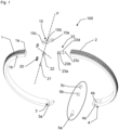
- FIG. 1 represents a clasp and a piece of jewelry 100 according to the present invention, in exploded and perspective view.
- the jewelry item 100 comprises a first portion 1 and a second portion 2 intended to, or arranged to, be attached together.
- the clasp for the jewelry item 100, comprises a fixing interface 21, here a screw 21, extending along a fixing axis F between a first end of the fixing interface 21 and a second end of the fixing interface 21.
- the clasp further comprises a pivot part 22 fixed to the second end of the fixing interface 21, and along the fixing axis F.
- the pivot part 22 may comprise a thread in order to receive the screw 21.
- the pivot part 22 may comprise a calibrated orifice in order to receive the pin or the pin and to be fixed thereto.
- the clasp further comprises a lock 10 forming a rocker mounted on the pivot part 22, a locking interface 10a, 23b of the portions 1, 2 of the jewelry item, and an elastic return element 20.
- the first portion 1 further comprises an opening 1a arranged to receive a shouldered rod 23 fixed to the second portion 2 at a rear part 23c of the shouldered rod 23.
- the rear part 23c can be fixed to the second portion 2 of the jewelry item 100 by screwing or driving.
- the shouldered rod 23 further comprises a front portion 23a which is free when the first portion 1 and the second portion 2 are detached, and which is retained by the lock 10 when the first portion 1 and the second portion 2 are attached together.
- the shouldered rod 23 further comprises a shoulder 23b (or a recess) arranged between the front portion 23a and the rear portion 23c.
- the shouldered rod 23 may further comprise a bulge 23d between the shoulder 23b and the rear portion 23c.
- the lock 10 comprises a beak 10a arranged to cooperate with the shoulder 23b in order to block the shouldered rod 23, and fix together the first portion 1 and the second portion 2 of the jewelry item 100.
- the beak 10a In the closed position, the beak 10a is thus housed in the shoulder 23b and can abut against the front portion 23a or the bulge 23d (or the rear portion 23c).
- the beak 10a and/or the front portion 23a may comprise an inclined slope or a chamfer in order to facilitate the insertion of the beak 10a into the shoulder 23b.
- the lock 10 further comprises a housing 10b, preferably circular, in order to house the pivot part 22.
- the lock 10 can thus tilt (or pivot) along a tilting axis B, perpendicular to a fixing axis F of the fixing interface 21.
- the lock 10 can be installed on the pivot part 22 by sliding the lock 10 into the pivot part 22 along the tilting axis B and then be introduced into the jewelry item 100 along the fixing axis F.
- the screw 21 can then be screwed into the thread of the pivot part 22.
- the pivot part 22 is thus assembled at a radial portion and not at its ends.
- the lock 10 is therefore mounted on a side face of the jewelry item 100 and is therefore at least partially hidden, and thus has the advantages mentioned above.
- the latch 10 further comprises a protrusion 10c in order to cooperate with an elastic return element 20, such as a coil spring or helical spring.
- the spring 20 makes it possible to return the latch 10 to the closed position.
- the protrusion 10c is arranged opposite the beak 10a.
- the housing 10b is arranged between the protrusion 10c and the beak 10a.
- the beak 10a is an example of a first end of the latch 10.
- the protrusion 10c is an example of a second end of the latch 10.
- the jewelry item 100 may further comprise a hinge, for example on a side opposite the clasp, in order to allow a greater opening of the jewelry item 100.
- the joint comprises a projection 3 of the first portion 1 and two forks 4 of the second portion 2.
- the projection 3 can be inserted between the two forks 4 and a hollow shaft 5a can be inserted into a through hole 3a of the projection 3 and two through holes 4a, 4b of the forks 4.
- the hollow shaft 5a comprises a screw head, a bushing 5b and a screw 5c in order to fix the hollow shaft 5a on the first portion 1 and the second portion 2.
- the bushing 5b is mounted between the two forks 4a, 4b.
- the hollow shaft 5a, with the bushing 5b and the screw 5c thus allows the rotation of the first portion 1 and the second portion 2.
- a pin 5 can replace the three parts to act as a hinge, as illustrated with reference to the Figure 4 .
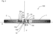
- FIG. 2 represents the clasp and the jewelry item 100 in top view and in partial cutaway.
- FIG. 2 shows the jewelry item 100 and the clasp in the closed position.
- the beak 10a is engaged with the shouldered rod 23 at the shoulder 23b.
- the lock 10 is mounted on the pivot piece 22 at the housing 10b, and can therefore tilt along the tilting axis B.
- the spring 20 forces the latch 10 into the closed position.
- the shouldered rod is secured in, or with, the second portion 2 of the jewelry item 100.
- the screw 21 secures the pivot piece 22 on the side opposite the latch 10.
- the lock 10 is at least partially concealed and housed in a housing 31 of the jewelry item 100, so as to be integrated with it.
- the lock 10 is thus visible from the side face, and is installed or mounted in the jewelry item 100 from the side face.
- the lock 10 is fixed to the jewelry item 100 by the screw 21, and is fixed in the fixing axis F.
- the beak 10a, the housing 10b and the protrusion 10c are substantially aligned along an extension axis E of the lock 10.
- FIG. 3 represents the clasp and the jewelry item 100 in a detail view, in exploded view and in perspective.
- the first portion 1 includes a clearance 30 to facilitate access to the lock 10 for the user.
- the lock 10 then switches to the open position (or unlocked state) and releases the beak 10 from the housing 23b of the shouldered rod 23.
- the latter When the user releases the pressure on the lock 10, the latter returns to the initial, closed position, because of the spring 20.
- the beak 10a can then engage with the housing 23b of the shouldered rod 23, in the closed position (or locking state) in order to attach the ends of the first portion 1 and the second portion 2.
- the pivot part 22 comprises a cylindrical portion 22a which can be housed in the housing 10d of the lock 10 in order to form a pivot connection.
- the pivot part 22 further comprises a shaft 22b with a part driven into the cylindrical portion 22a and a tapping in order to receive the thread of the screw 21.
- the shaft 22b and the cylindrical portion 22a can be made in a single piece or in a single piece as can be seen in Figure 4 .
- FIG. 4 represents the clasp and the jewelry item 100 according to the present invention, in exploded and perspective view, in a view opposite that of the Figure 1 .
- the housing 31 makes it possible to house the lock 10 in particular.
- the housing 31 can also house the spring 20 and the pivot part 22.
- the housing 31 can also receive the shouldered rod 23 when the jewelry item 100 is in the closed position.
- the 100th Jewelry Item of the Figure 4 differs from that of the Figure 1 in particular in that pin 5 can replace the three parts of the Figure 1 acting as a hinge (hollow shaft 5a, bushing 5b and screw 5c).
Landscapes
- Adornments (AREA)
Applications Claiming Priority (1)
| Application Number | Priority Date | Filing Date | Title |
|---|---|---|---|
| CH11972023 | 2023-10-26 |
Publications (1)
| Publication Number | Publication Date |
|---|---|
| EP4544951A1 true EP4544951A1 (de) | 2025-04-30 |
Family
ID=95250427
Family Applications (1)
| Application Number | Title | Priority Date | Filing Date |
|---|---|---|---|
| EP24204464.2A Pending EP4544951A1 (de) | 2023-10-26 | 2024-10-03 | Verschluss für armband |
Country Status (1)
| Country | Link |
|---|---|
| EP (1) | EP4544951A1 (de) |
Citations (4)
| Publication number | Priority date | Publication date | Assignee | Title |
|---|---|---|---|---|
| US4879883A (en) * | 1988-08-09 | 1989-11-14 | Bruner Mates A | Openable ring with unique locking and release means |
| US4991409A (en) * | 1988-12-23 | 1991-02-12 | Creates Allan B | Openable ring with safety snap lock element |
| US6481069B1 (en) * | 2000-10-17 | 2002-11-19 | Howard Cheng | Bracelet connector |
| FR3007782A1 (fr) | 2013-06-28 | 2015-01-02 | Vuitton Louis Sa | Fermoir de securite et article pourvu d'un tel fermoir |
-
2024
- 2024-10-03 EP EP24204464.2A patent/EP4544951A1/de active Pending
Patent Citations (4)
| Publication number | Priority date | Publication date | Assignee | Title |
|---|---|---|---|---|
| US4879883A (en) * | 1988-08-09 | 1989-11-14 | Bruner Mates A | Openable ring with unique locking and release means |
| US4991409A (en) * | 1988-12-23 | 1991-02-12 | Creates Allan B | Openable ring with safety snap lock element |
| US6481069B1 (en) * | 2000-10-17 | 2002-11-19 | Howard Cheng | Bracelet connector |
| FR3007782A1 (fr) | 2013-06-28 | 2015-01-02 | Vuitton Louis Sa | Fermoir de securite et article pourvu d'un tel fermoir |
Similar Documents
| Publication | Publication Date | Title |
|---|---|---|
| EP3266333B1 (de) | Armbanduhr und schmuckstück mit austauschbarem armband | |
| CH715584A1 (fr) | Embout arrangé pour être fixé de façon amovible à une barrette. | |
| EP0661938B1 (de) | Faltverschluss für armbänder | |
| EP1404190B1 (de) | Schwenkbarer offener ring | |
| WO2021116560A1 (fr) | Dispositif d'assemblage amovible entre deux pièces | |
| EP0862097B1 (de) | Bandanschlusssteg zum Befestigen eines Armbandes und eine mit einem solchen Steg versehene Uhr | |
| EP1664940B1 (de) | Vorrichtung zur befestigung eines armbandes | |
| EP4544951A1 (de) | Verschluss für armband | |
| WO2017207880A1 (fr) | Objet décoratif, tel qu'un bijou, comprenant un corps et un élément décoratif fixé de manière réversible au corps | |
| CH721248A1 (fr) | Fermoir pour article de joaillerie | |
| EP4018875A1 (de) | Armband | |
| CH720830A2 (fr) | Dispositif de boucle interchangeable | |
| EP3753439B1 (de) | Abnehmbare mechanische verbindungsvorrichtung zwischen einem armband und einem mechanischen teil | |
| FR2743641A1 (fr) | Montre-bracelet a cornes munie d'un dispositif de fixation d'un bracelet aux cornes et bracelet pour une telle montre | |
| CH712040B1 (fr) | Fermoir déployant pour bracelet. | |
| FR3042389A1 (fr) | Systeme de verrouillage rapide d'une piece amovible et interchangeable par rapport a une piece fixe | |
| FR2893153A1 (fr) | Dispositif de fixation d'un bracelet de montre | |
| EP4264066B1 (de) | Dekorativer artikel und befestigungssystem | |
| CH690519A5 (fr) | Montre-bracelet à cornes munie d'un dispositif de fixation d'un bracelet aux cornes et bracelet notamment pour une telle montre. | |
| CH720829A2 (fr) | Dispositif de boucle interchangeable | |
| EP4473862A1 (de) | Austauschbare schnallenvorrichtung | |
| FR3163535A1 (fr) | Boucle de ceinture, notamment de maroquinerie, et ceinture, notamment de maroquinerie, comportant une telle boucle | |
| CH713974A2 (fr) | Dispositif de liaison mécanique pour composants d'habillage horloger, notamment en forme de barrette de fixation. | |
| CH718228B1 (fr) | Dispositif d'attache d'un bracelet à une pièce d'horlogerie, de bijouterie ou de joaillerie. | |
| EP4473863A1 (de) | Austauschbare schnallenvorrichtung |
Legal Events
| Date | Code | Title | Description |
|---|---|---|---|
| PUAI | Public reference made under article 153(3) epc to a published international application that has entered the european phase |
Free format text: ORIGINAL CODE: 0009012 |
|
| STAA | Information on the status of an ep patent application or granted ep patent |
Free format text: STATUS: THE APPLICATION HAS BEEN PUBLISHED |
|
| AK | Designated contracting states |
Kind code of ref document: A1 Designated state(s): AL AT BE BG CH CY CZ DE DK EE ES FI FR GB GR HR HU IE IS IT LI LT LU LV MC ME MK MT NL NO PL PT RO RS SE SI SK SM TR |
|
| STAA | Information on the status of an ep patent application or granted ep patent |
Free format text: STATUS: REQUEST FOR EXAMINATION WAS MADE |
|
| 17P | Request for examination filed |
Effective date: 20251022 |