EP4542999A2 - Verfahren und vorrichtung zur verarbeitung eines videosignals - Google Patents
Verfahren und vorrichtung zur verarbeitung eines videosignals Download PDFInfo
- Publication number
- EP4542999A2 EP4542999A2 EP25151170.5A EP25151170A EP4542999A2 EP 4542999 A2 EP4542999 A2 EP 4542999A2 EP 25151170 A EP25151170 A EP 25151170A EP 4542999 A2 EP4542999 A2 EP 4542999A2
- Authority
- EP
- European Patent Office
- Prior art keywords
- block
- current block
- prediction
- sample
- motion vector
- Prior art date
- Legal status (The legal status is an assumption and is not a legal conclusion. Google has not performed a legal analysis and makes no representation as to the accuracy of the status listed.)
- Pending
Links
Images


Classifications
-
- H—ELECTRICITY
- H04—ELECTRIC COMMUNICATION TECHNIQUE
- H04N—PICTORIAL COMMUNICATION, e.g. TELEVISION
- H04N19/00—Methods or arrangements for coding, decoding, compressing or decompressing digital video signals
- H04N19/10—Methods or arrangements for coding, decoding, compressing or decompressing digital video signals using adaptive coding
- H04N19/102—Methods or arrangements for coding, decoding, compressing or decompressing digital video signals using adaptive coding characterised by the element, parameter or selection affected or controlled by the adaptive coding
- H04N19/103—Selection of coding mode or of prediction mode
- H04N19/11—Selection of coding mode or of prediction mode among a plurality of spatial predictive coding modes
-
- H—ELECTRICITY
- H04—ELECTRIC COMMUNICATION TECHNIQUE
- H04N—PICTORIAL COMMUNICATION, e.g. TELEVISION
- H04N19/00—Methods or arrangements for coding, decoding, compressing or decompressing digital video signals
- H04N19/10—Methods or arrangements for coding, decoding, compressing or decompressing digital video signals using adaptive coding
- H04N19/102—Methods or arrangements for coding, decoding, compressing or decompressing digital video signals using adaptive coding characterised by the element, parameter or selection affected or controlled by the adaptive coding
- H04N19/117—Filters, e.g. for pre-processing or post-processing
-
- H—ELECTRICITY
- H04—ELECTRIC COMMUNICATION TECHNIQUE
- H04N—PICTORIAL COMMUNICATION, e.g. TELEVISION
- H04N19/00—Methods or arrangements for coding, decoding, compressing or decompressing digital video signals
- H04N19/10—Methods or arrangements for coding, decoding, compressing or decompressing digital video signals using adaptive coding
- H04N19/134—Methods or arrangements for coding, decoding, compressing or decompressing digital video signals using adaptive coding characterised by the element, parameter or criterion affecting or controlling the adaptive coding
- H04N19/136—Incoming video signal characteristics or properties
- H04N19/137—Motion inside a coding unit, e.g. average field, frame or block difference
- H04N19/139—Analysis of motion vectors, e.g. their magnitude, direction, variance or reliability
-
- H—ELECTRICITY
- H04—ELECTRIC COMMUNICATION TECHNIQUE
- H04N—PICTORIAL COMMUNICATION, e.g. TELEVISION
- H04N19/00—Methods or arrangements for coding, decoding, compressing or decompressing digital video signals
- H04N19/10—Methods or arrangements for coding, decoding, compressing or decompressing digital video signals using adaptive coding
- H04N19/169—Methods or arrangements for coding, decoding, compressing or decompressing digital video signals using adaptive coding characterised by the coding unit, i.e. the structural portion or semantic portion of the video signal being the object or the subject of the adaptive coding
- H04N19/17—Methods or arrangements for coding, decoding, compressing or decompressing digital video signals using adaptive coding characterised by the coding unit, i.e. the structural portion or semantic portion of the video signal being the object or the subject of the adaptive coding the unit being an image region, e.g. an object
- H04N19/176—Methods or arrangements for coding, decoding, compressing or decompressing digital video signals using adaptive coding characterised by the coding unit, i.e. the structural portion or semantic portion of the video signal being the object or the subject of the adaptive coding the unit being an image region, e.g. an object the region being a block, e.g. a macroblock
-
- H—ELECTRICITY
- H04—ELECTRIC COMMUNICATION TECHNIQUE
- H04N—PICTORIAL COMMUNICATION, e.g. TELEVISION
- H04N19/00—Methods or arrangements for coding, decoding, compressing or decompressing digital video signals
- H04N19/20—Methods or arrangements for coding, decoding, compressing or decompressing digital video signals using video object coding
- H04N19/23—Methods or arrangements for coding, decoding, compressing or decompressing digital video signals using video object coding with coding of regions that are present throughout a whole video segment, e.g. sprites, background or mosaic
-
- H—ELECTRICITY
- H04—ELECTRIC COMMUNICATION TECHNIQUE
- H04N—PICTORIAL COMMUNICATION, e.g. TELEVISION
- H04N19/00—Methods or arrangements for coding, decoding, compressing or decompressing digital video signals
- H04N19/50—Methods or arrangements for coding, decoding, compressing or decompressing digital video signals using predictive coding
- H04N19/503—Methods or arrangements for coding, decoding, compressing or decompressing digital video signals using predictive coding involving temporal prediction
- H04N19/51—Motion estimation or motion compensation
- H04N19/513—Processing of motion vectors
-
- H—ELECTRICITY
- H04—ELECTRIC COMMUNICATION TECHNIQUE
- H04N—PICTORIAL COMMUNICATION, e.g. TELEVISION
- H04N19/00—Methods or arrangements for coding, decoding, compressing or decompressing digital video signals
- H04N19/50—Methods or arrangements for coding, decoding, compressing or decompressing digital video signals using predictive coding
- H04N19/503—Methods or arrangements for coding, decoding, compressing or decompressing digital video signals using predictive coding involving temporal prediction
- H04N19/51—Motion estimation or motion compensation
- H04N19/537—Motion estimation other than block-based
- H04N19/54—Motion estimation other than block-based using feature points or meshes
-
- H—ELECTRICITY
- H04—ELECTRIC COMMUNICATION TECHNIQUE
- H04N—PICTORIAL COMMUNICATION, e.g. TELEVISION
- H04N19/00—Methods or arrangements for coding, decoding, compressing or decompressing digital video signals
- H04N19/50—Methods or arrangements for coding, decoding, compressing or decompressing digital video signals using predictive coding
- H04N19/593—Methods or arrangements for coding, decoding, compressing or decompressing digital video signals using predictive coding involving spatial prediction techniques
-
- H—ELECTRICITY
- H04—ELECTRIC COMMUNICATION TECHNIQUE
- H04N—PICTORIAL COMMUNICATION, e.g. TELEVISION
- H04N19/00—Methods or arrangements for coding, decoding, compressing or decompressing digital video signals
- H04N19/85—Methods or arrangements for coding, decoding, compressing or decompressing digital video signals using pre-processing or post-processing specially adapted for video compression
Definitions
- the present invention relates to a method and an apparatus for processing video signal.
- HD images high definition (HD) images and ultra-high definition (UHD) images
- UHD ultra-high definition
- higher resolution and quality image data has increasing amounts of data in comparison with conventional image data. Therefore, when transmitting image data by using a medium such as conventional wired and wireless broadband networks, or when storing image data by using a conventional storage medium, costs of transmitting and storing increase.
- high-efficiency image encoding/decoding techniques may be utilized.
- Image compression technology includes various techniques, including: an inter-prediction technique of predicting a pixel value included in a current picture from a previous or subsequent picture of the current picture; an intra-prediction technique of predicting a pixel value included in a current picture by using pixel information in the current picture; an entropy encoding technique of assigning a short code to a value with a high appearance frequency and assigning a long code to a value with a low appearance frequency; etc.
- Image data may be effectively compressed by using such image compression technology, and may be transmitted or stored.
- An object of the present invention is intended to provide a method and an apparatus for encoding/decoding a video signal, the method and the apparatus hierarchically partitioning a coding block.
- An object of the present invention is intended to provide a method and an apparatus for encoding/decoding a video signal, the method and the apparatus performing intra prediction of an encoding/decoding target block.
- An object of the present invention is intended to provide a method and an apparatus for encoding/decoding a video signal, the method and the apparatus correcting a prediction sample of an encoding/decoding target block.
- An object of the present invention is intended to provide a method and an apparatus for encoding/decoding a video signal, the method and the apparatus updating the first prediction sample generated through intra prediction to the second prediction sample by using offset.
- An object of the present invention is intended to provide a method and an apparatus for encoding/decoding a video signal, the inter prediction method and the apparatus based on a motion model.
- An object of the present invention is intended to provide a method and an apparatus for encoding/decoding a video signal, the method and the apparatus filtering reference samples for intra prediction.
- a method and apparatus for decoding a video signal including: generating a first prediction sample by performing intra prediction on a current block; determining an intra prediction pattern specifying a pattern in which the current block is partitioned into sub-blocks; determining offset in sub-block units of the current block based on the intra prediction pattern; and generating a second prediction sample in sub-block units of the current block by using the first prediction sample and the offset.
- the current block may include multiple sub-blocks, and whether or not the offset is set for each sub-block may be determined.
- whether or not the offset is set for a sub-block may be determined based on a position of the sub-block.
- the current block may include multiple sub-blocks, and the offset may be set to a different value for each sub-block.
- the offset may be derived from a reference sample adjacent to the current block.
- a method and apparatus for decoding a video signal comprising: deriving an affine motion vector using a plurality of motion vector related to a current block; and performing a motion compensation based on the derived affine motion vector and a position of a current sample.
- the plurality of motion vectors being correspond to a plurality of motion vectors of corner samples included in the current block;
- the plurality of motion vectors comprises a motion vector of a top left corner sample of the current block and a motion vector of a top right corner sample of the current block.
- the current block is partitioned into a plurality of sub-blocks, and the motion compensation is performed in units of sub-block using the derived affine motion vector.
- the plurality of motion vectors is derived using a motion vector of a neighboring block of the current block.
- the present invention it is possible to effectively determine an intra prediction mode of an encoding/decoding target block, and to enhance accuracy of intra prediction.
- a method and apparatus for decoding a video signal including: generating a first prediction sample by performing intra prediction on a current block; determining an intra prediction pattern specifying a pattern in which the current block is partitioned into sub-blocks; determining offset in sub-block units of the current block based on the intra prediction pattern; and generating a second prediction sample in sub-block units of the current block by using the first prediction sample and the offset.
- the current block may include multiple sub-blocks, and whether or not the offset is set for each sub-block may be determined.
- whether or not the offset is set for a sub-block may be determined based on a position of the sub-block.
- the current block may include multiple sub-blocks, and the offset may be set to a different value for each sub-block.
- the offset may be derived from a reference sample adjacent to the current block.
- a method and apparatus for decoding a video signal comprising: deriving an affine motion vector using a plurality of motion vector related to a current block; and performing a motion compensation based on the derived affine motion vector and a position of a current sample.
- the plurality of motion vectors being correspond to a plurality of motion vectors of corner samples included in the current block;
- the plurality of motion vectors comprises a motion vector of a top left corner sample of the current block and a motion vector of a top right corner sample of the current block.
- the current block is partitioned into a plurality of sub-blocks, and the motion compensation is performed in units of sub-block using the derived affine motion vector.
- the plurality of motion vectors is derived using a motion vector of a neighboring block of the current block.
- 'first', 'second', etc. can be used to describe various components, but the components are not to be construed as being limited to the terms. The terms are only used to differentiate one component from other components.
- the 'first' component may be named the 'second' component without departing from the scope of the present invention, and the 'second' component may also be similarly named the 'first' component.
- the term 'and/or' includes a combination of a plurality of items or any one of a plurality of terms.
- FIG. 1 is a block diagram illustrating a device for encoding a video according to an embodiment of the present invention.
- the device 100 for encoding a video may include: a picture partitioning module 110, prediction modules 120 and 125, a transform module 130, a quantization module 135, a rearrangement module 160, an entropy encoding module 165, an inverse quantization module 140, an inverse transform module 145, a filter module 150, and a memory 155.
- each constitutional part shown in FIG. 1 are independently shown so as to represent characteristic functions different from each other in the device for encoding a video.
- each constitutional part is constituted in a constitutional unit of separated hardware or software.
- each constitutional part includes each of enumerated constitutional parts for convenience.
- at least two constitutional parts of each constitutional part may be combined to form one constitutional part or one constitutional part may be divided into a plurality of constitutional parts to perform each function.
- the embodiment where each constitutional part is combined and the embodiment where one constitutional part is divided are also included in the scope of the present invention, if not departing from the essence of the present invention.
- constituents may not be indispensable constituents performing essential functions of the present invention but be selective constituents improving only performance thereof.
- the present invention may be implemented by including only the indispensable constitutional parts for implementing the essence of the present invention except the constituents used in improving performance.
- the structure including only the indispensable constituents except the selective constituents used in improving only performance is also included in the scope of the present invention.
- the picture partitioning module 110 may partition an input picture into one or more processing units.
- the processing unit may be a prediction unit (PU), a transform unit (TU), or a coding unit (CU).
- the picture partitioning module 110 may partition one picture into combinations of multiple coding units, prediction units, and transform units, and may encode a picture by selecting one combination of coding units, prediction units, and transform units with a predetermined criterion (e.g., cost function).
- a predetermined criterion e.g., cost function
- one picture may be partitioned into multiple coding units.
- a recursive tree structure such as a quad tree structure, may be used to partition a picture into coding units.
- a coding unit which is partitioned into other coding units with one picture or a largest coding unit as a root may be partitioned with child nodes corresponding to the number of partitioned coding units.
- a coding unit which is no longer partitioned by a predetermined limitation serves as a leaf node. That is, when it is assumed that only square partitioning is possible for one coding unit, one coding unit may be partitioned into four other coding units at most.
- the coding unit may mean a unit performing encoding, or a unit performing decoding.
- a prediction unit may be one of partitions partitioned into a square or a rectangular shape having the same size in a single coding unit, or a prediction unit may be one of partitions partitioned so as to have a different shape / size in a single coding unit.
- intra prediction may be performed without partitioning the coding unit into multiple prediction units NxN.
- the prediction modules 120 and 125 may include an inter prediction module 120 performing inter prediction and an intra prediction module 125 performing intra prediction. Whether to perform inter prediction or intra prediction for the prediction unit may be determined, and detailed information (e.g., an intra prediction mode, a motion vector, a reference picture, etc.) according to each prediction method may be determined.
- the processing unit subjected to prediction may be different from the processing unit for which the prediction method and detailed content is determined.
- the prediction method, the prediction mode, etc. may be determined by the prediction unit, and prediction may be performed by the transform unit.
- a residual value (residual block) between the generated prediction block and an original block may be input to the transform module 130.
- the used for prediction may be encoded with the residual value by the entropy encoding module 165 and may be transmitted to a device for decoding a video.
- a particular encoding mode it is possible to transmit to a device for decoding video by encoding the original block as it is without generating the prediction block through the prediction modules 120 and 125.
- the inter prediction module 120 may predict the prediction unit based on information of at least one of a previous picture or a subsequent picture of the current picture, or may predict the prediction unit based on information of some encoded regions in the current picture, in some cases.
- the inter prediction module 120 may include a reference picture interpolation module, a motion prediction module, and a motion compensation module.
- the reference picture interpolation module may receive reference picture information from the memory 155 and may generate pixel information of an integer pixel or less then the integer pixel from the reference picture.
- an 8-tap DCT-based interpolation filter having different filter coefficients may be used to generate pixel information of an integer pixel or less than an integer pixel in units of a 1/4 pixel.
- a 4-tap DCT-based interpolation filter having different filter coefficient may be used to generate pixel information of an integer pixel or less than an integer pixel in units of a 1/8 pixel.
- the motion prediction module may perform motion prediction based on the reference picture interpolated by the reference picture interpolation module.
- various methods such as a full search-based block matching algorithm (FBMA), a three step search (TSS), a new three-step search algorithm (NTS), etc.
- FBMA full search-based block matching algorithm
- TSS three step search
- NTS new three-step search algorithm
- the motion vector may have a motion vector value in units of a 1/2 pixel or a 1/4 pixel based on an interpolated pixel.
- the motion prediction module may predict a current prediction unit by changing the motion prediction method.
- various methods such as a skip method, a merge method, an AMVP (Advanced Motion Vector Prediction) method, an intra block copy method, etc., may be used.
- AMVP Advanced Motion Vector Prediction
- the intra prediction module 125 may generate a prediction unit based on reference pixel information neighboring to a current block which is pixel information in the current picture.
- the neighboring block of the current prediction unit is a block subjected to inter prediction and thus a reference pixel is a pixel subjected to inter prediction
- the reference pixel included in the block subjected to inter prediction may be replaced with reference pixel information of a neighboring block subjected to intra prediction. That is, when a reference pixel is not available, at least one reference pixel of available reference pixels may be used instead of unavailable reference pixel information.
- Prediction modes in intra prediction may include a directional prediction mode using reference pixel information depending on a prediction direction and a non-directional prediction mode not using directional information in performing prediction.
- a mode for predicting luma information may be different from a mode for predicting chroma information, and in order to predict the chroma information, intra prediction mode information used to predict luma information or predicted luma signal information may be utilized.
- intra prediction when the size of the prediction unit is the same as the size of the transform unit, intra prediction may be performed on the prediction unit based on pixels positioned at the left, the top left, and the top of the prediction unit. However, in performing intra prediction, when the size of the prediction unit is different from the size of the transform unit, intra prediction may be performed using a reference pixel based on the transform unit. Also, intra prediction using N x N partitioning may be used for only the smallest coding unit.
- a prediction block may be generated after applying an AIS (Adaptive Intra Smoothing) filter to a reference pixel depending on the prediction modes.
- the type of the AIS filter applied to the reference pixel may vary.
- an intra prediction mode of the current prediction unit may be predicted from the intra prediction mode of the prediction unit neighboring to the current prediction unit.
- mode information predicted from the neighboring prediction unit when the intra prediction mode of the current prediction unit is the same as the intra prediction mode of the neighboring prediction unit, information indicating that the prediction modes of the current prediction unit and the neighboring prediction unit are equal to each other may be transmitted using predetermined flag information.
- entropy encoding may be performed to encode prediction mode information of the current block.
- a residual block including information on a residual value which is a different between the prediction unit subjected to prediction and the original block of the prediction unit may be generated based on prediction units generated by the prediction modules 120 and 125.
- the generated residual block may be input to the transform module 130.
- the transform module 130 may transform the residual block including the information on the residual value between the original block and the prediction unit generated by the prediction modules 120 and 125 by using a transform method, such as discrete cosine transform (DCT), discrete sine transform (DST), and KLT. Whether to apply DCT, DST, or KLT in order to transform the residual block may be determined based on intra prediction mode information of the prediction unit used to generate the residual block.
- a transform method such as discrete cosine transform (DCT), discrete sine transform (DST), and KLT.
- the quantization module 135 may quantize values transformed to a frequency domain by the transform module 130. Quantization coefficients may vary depending on the block or importance of a picture. The values calculated by the quantization module 135 may be provided to the inverse quantization module 140 and the rearrangement module 160.
- the rearrangement module 160 may rearrange coefficients of quantized residual values.
- the rearrangement module 160 may change a coefficient in the form of a two-dimensional block into a coefficient in the form of a one-dimensional vector through a coefficient scanning method. For example, the rearrangement module 160 may scan from a DC coefficient to a coefficient in a high frequency domain using a zigzag scanning method so as to change the coefficients to be in the form of one-dimensional vectors.
- vertical direction scanning where coefficients in the form of two-dimensional blocks are scanned in the column direction or horizontal direction scanning where coefficients in the form of two-dimensional blocks are scanned in the row direction may be used instead of zigzag scanning. That is, which scanning method among zigzag scanning, vertical direction scanning, and horizontal direction scanning is used may be determined depending on the size of the transform unit and the intra prediction mode.
- the entropy encoding module 165 may perform entropy encoding based on the values calculated by the rearrangement module 160. Entropy encoding may use various encoding methods, for example, exponential Golomb coding, context-adaptive variable length coding (CAVLC), and context-adaptive binary arithmetic coding (CABAC).
- CAVLC context-adaptive variable length coding
- CABAC context-adaptive binary arithmetic coding
- the entropy encoding module 165 may encode a variety of information, such as residual value coefficient information and block type information of the coding unit, prediction mode information, partition unit information, prediction unit information, transform unit information, motion vector information, reference frame information, block interpolation information, filtering information, etc. from the rearrangement module 160 and the prediction modules 120 and 125.
- the entropy encoding module 165 may entropy encode the coefficients of the coding unit input from the rearrangement module 160.
- the inverse quantization module 140 may inversely quantize the values quantized by the quantization module 135 and the inverse transform module 145 may inversely transform the values transformed by the transform module 130.
- the residual value generated by the inverse quantization module 140 and the inverse transform module 145 may be combined with the prediction unit predicted by a motion estimation module, a motion compensation module, and the intra prediction module of the prediction modules 120 and 125 such that a reconstructed block can be generated.
- the filter module 150 may include at least one of a deblocking filter, an offset correction unit, and an adaptive loop filter (ALF).
- a deblocking filter may include at least one of a deblocking filter, an offset correction unit, and an adaptive loop filter (ALF).
- ALF adaptive loop filter
- the deblocking filter may remove block distortion that occurs due to boundaries between the blocks in the reconstructed picture.
- the pixels included in several rows or columns in the block may be a basis of determining whether to apply the deblocking filter to the current block.
- a strong filter or a weak filter may be applied depending on required deblocking filtering strength.
- horizontal direction filtering and vertical direction filtering may be processed in parallel.
- the offset correction module may correct offset with the original picture in units of a pixel in the picture subjected to deblocking.
- Adaptive loop filtering may be performed based on the value obtained by comparing the filtered reconstructed picture and the original picture.
- the pixels included in the picture may be divided into predetermined groups, a filter to be applied to each of the groups may be determined, and filtering may be individually performed for each group.
- Information on whether to apply ALF and a luma signal may be transmitted by coding units (CU).
- the shape and filter coefficient of a filter for ALF may vary depending on each block. Also, the filter for ALF in the same shape (fixed shape) may be applied regardless of characteristics of the application target block.
- the memory 155 may store the reconstructed block or picture calculated through the filter module 150.
- the stored reconstructed block or picture may be provided to the prediction modules 120 and 125 in performing inter prediction.
- FIG. 2 is a block diagram illustrating a device for decoding a video according to an embodiment of the present invention.
- the device 200 for decoding a video may include: an entropy decoding module 210, a rearrangement module 215, an inverse quantization module 220, an inverse transform module 225, prediction modules 230 and 235, a filter module 240, and a memory 245.
- the input bitstream may be decoded according to an inverse process of the device for encoding a video.
- the entropy decoding module 210 may perform entropy decoding according to an inverse process of entropy encoding by the entropy encoding module of the device for encoding a video. For example, corresponding to the methods performed by the device for encoding a video, various methods, such as exponential Golomb coding, context-adaptive variable length coding (CAVLC), and context-adaptive binary arithmetic coding (CABAC) may be applied.
- various methods such as exponential Golomb coding, context-adaptive variable length coding (CAVLC), and context-adaptive binary arithmetic coding (CABAC) may be applied.
- the entropy decoding module 210 may decode information on intra prediction and inter prediction performed by the device for encoding a video.
- the rearrangement module 215 may perform rearrangement on the bitstream entropy decoded by the entropy decoding module 210 based on the rearrangement method used in the device for encoding a video.
- the rearrangement module may reconstruct and rearrange the coefficients in the form of one-dimensional vectors to the coefficient in the form of two-dimensional blocks.
- the rearrangement module 215 may receive information related to coefficient scanning performed in the device for encoding a video and may perform rearrangement via a method of inversely scanning the coefficients based on the scanning order performed in the device for encoding a video.
- the inverse quantization module 220 may perform inverse quantization based on a quantization parameter received from the device for encoding a video and the rearranged coefficients of the block.
- the inverse transform module 225 may perform the inverse transform, i.e., inverse DCT, inverse DST, and inverse KLT, which is the inverse process of transform, i.e., DCT, DST, and KLT, performed by the transform module on the quantization result by the device for encoding a video.
- Inverse transform may be performed based on a transfer unit determined by the device for encoding a video.
- the inverse transform module 225 of the device for decoding a video may selectively perform transform schemes (e.g., DCT, DST, and KLT) depending on multiple pieces of information, such as the prediction method, the size of the current block, the prediction direction, etc.
- transform schemes e.g., DCT, DST, and KLT
- the prediction modules 230 and 235 may generate a prediction block based on information on prediction block generation received from the entropy decoding module 210 and previously decoded block or picture information received from the memory 245.
- intra prediction when the size of the prediction unit is the same as the size of the transform unit, intra prediction may be performed on the prediction unit based on the pixels positioned at the left, the top left, and the top of the prediction unit.
- intra prediction when the size of the prediction unit is different from the size of the transform unit, intra prediction may be performed using a reference pixel based on the transform unit.
- intra prediction using N x N partitioning may be used for only the smallest coding unit.
- the prediction modules 230 and 235 may include a prediction unit determination module, an inter prediction module, and an intra prediction module.
- the prediction unit determination module may receive a variety of information, such as prediction unit information, prediction mode information of an intra prediction method, information on motion prediction of an inter prediction method, etc. from the entropy decoding module 210, may divide a current coding unit into prediction units, and may determine whether inter prediction or intra prediction is performed on the prediction unit.
- the inter prediction module 230 may perform inter prediction on the current prediction unit based on information of at least one of a previous picture or a subsequent picture of the current picture including the current prediction unit. Alternatively, inter prediction may be performed based on information of some pre-reconstructed regions in the current picture including the current prediction unit.
- the coding unit In order to perform inter prediction, it may be determined for the coding unit which of a skip mode, a merge mode, an AMVP mode, and an inter block copy mode is used as the motion prediction method of the prediction unit included in the coding unit.
- the intra prediction module 235 may generate a prediction block based on pixel information in the current picture.
- intra prediction may be performed based on intra prediction mode information of the prediction unit received from the device for encoding a video.
- the intra prediction module 235 may include an adaptive intra smoothing (AIS) filter, a reference pixel interpolation module, and a DC filter.
- the AIS filter performs filtering on the reference pixel of the current block, and whether to apply the filter may be determined depending on the prediction mode of the current prediction unit.
- AIS filtering may be performed on the reference pixel of the current block by using the prediction mode of the prediction unit and AIS filter information received from the device for encoding a video.
- the prediction mode of the current block is a mode where AIS filtering is not performed, the AIS filter may not be applied.
- the reference pixel interpolation module may interpolate the reference pixel to generate the reference pixel of an integer pixel or less than an integer pixel.
- the prediction mode of the current prediction unit is a prediction mode in which a prediction block is generated without interpolation the reference pixel, the reference pixel may not be interpolated.
- the DC filter may generate a prediction block through filtering when the prediction mode of the current block is a DC mode.
- the reconstructed block or picture may be provided to the filter module 240.
- the filter module 240 may include the deblocking filter, the offset correction module, and the ALF.
- the deblocking filter of the device for decoding a video may receive information on the deblocking filter from the device for encoding a video, and may perform deblocking filtering on the corresponding block.
- the offset correction module may perform offset correction on the reconstructed picture based on the type of offset correction and offset value information applied to a picture in performing encoding.
- the ALF may be applied to the coding unit based on information on whether to apply the ALF, ALF coefficient information, etc. received from the device for encoding a video.
- the ALF information may be provided as being included in a particular parameter set.
- the memory 245 may store the reconstructed picture or block for use as a reference picture or block, and may provide the reconstructed picture to an output module.
- the coding unit is used as a term representing a unit for encoding, but the coding unit may serve as a unit performing decoding as well as encoding.
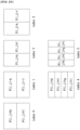
- FIG. 3 is a view illustrating an example of hierarchically partitioning a coding block based on a tree structure according to an embodiment of the present invention.
- An input video signal is decoded in predetermined block units.
- a default unit for decoding the input video signal is a coding block.
- the coding block may be a unit performing intra/inter prediction, transform, and quantization.
- the coding block may be a square or non-square block having an arbitrary size in a range of 8x8 to 64x64, or may be a square or non-square block having a size of 128x128, 256x256, or more.
- the coding block may be hierarchically partitioned based on at least one of a quad tree and a binary tree.
- quad tree-based partitioning may mean that a 2Nx2N coding block is partitioned into four NxN coding blocks
- binary tree-based partitioning may mean that one coding block is partitioned into two coding blocks.
- Binary tree-based partitioning may be symmetrically or asymmetrically performed.
- the coding block partitioned based on the binary tree may be a square block or a non-square block, such as a rectangular shape.
- Binary tree-based partitioning may be performed on a coding block where quad tree-based partitioning is no longer performed.
- Quad tree-based partitioning may no longer be performed on the coding block partitioned based on the binary tree.
- information indicating quad tree-based partitioning, information on the size/depth of the coding block that quad tree-based partitioning is allowed, information indicating binary tree-based partitioning, information on the size/depth of the coding block that binary tree-based partitioning is allowed, information on the size/depth of the coding block that binary tree-based partitioning is not allowed, information on whether binary tree-based partitioning is performed in a vertical direction or a horizontal direction, etc. may be used.
- the first coding block 300 with the partition depth (split depth) of k may be partitioned into multiple second coding blocks based on the quad tree.
- the second coding blocks 310 to 340 may be square blocks having the half width and the half height of the first coding block, and the partition depth of the second coding block may be increased to k+1.
- the second coding block 310 with the partition depth of k+1 may be partitioned into multiple third coding blocks with the partition depth of k+2. Partitioning of the second coding block 310 may be performed by selectively using one of the quad tree and the binary tree depending on a partitioning method.
- the partitioning method may be determined based on at least one of the information indicating quad tree-based partitioning and the information indicating binary tree-based partitioning.
- the second coding block 310 When the second coding block 310 is partitioned based on the quad tree, the second coding block 310 may be partitioned into four third coding blocks 310a having the half width and the half height of the second coding block, and the partition depth of the third coding block 310a may be increased to k+2. In contrast, when the second coding block 310 is partitioned based on the binary tree, the second coding block 310 may be partitioned into two third coding blocks. Here, each of two third coding blocks may be a non-square block having one of the half width and the half height of the second coding block, and the partition depth may be increased to k+2.
- the second coding block may be determined as a non-square block of a horizontal direction or a vertical direction depending on a partitioning direction, and the partitioning direction may be determined based on the information on whether binary tree-based partitioning is performed in a vertical direction or a horizontal direction.
- the second coding block 310 may be determined as a leaf coding block that is no longer partitioned based on the quad tree or the binary tree.
- the leaf coding block may be used as a prediction block or a transform block.
- the third coding block 310a may be determined as a leaf coding block, or may be further partitioned based on the quad tree or the binary tree.
- the third coding block 310b partitioned based on the binary tree may be further partitioned into coding blocks 310b-2 of a vertical direction or coding blocks 310b-3 of a horizontal direction based on the binary tree, and the partition depth of the relevant coding blocks may be increased to k+3.
- the third coding block 310b may be determined as a leaf coding block 310b-1 that is no longer partitioned based on the binary tree.
- the coding block 310b-1 may be used as a prediction block or a transform block.
- the above partitioning process may be limitedly performed based on at least one of the information on the size/depth of the coding block that quad tree-based partitioning is allowed, the information on the size/depth of the coding block that binary tree-based partitioning is allowed, and the information on the size/depth of the coding block that binary tree-based partitioning is not allowed.
- FIG. 4 is a view illustrating types of pre-defined intra prediction modes for a device for encoding/decoding a video according to an embodiment of the present invention.
- the device for encoding/decoding a video may perform intra prediction using one of pre-defined intra prediction modes.
- the pre-defined intra prediction modes for intra prediction may include non-directional prediction modes (e.g., a planar mode, a DC mode) and 33 directional prediction modes.
- M extended directional prediction modes may be defined by subdividing angles of the directional prediction modes (M>33), and a directional prediction mode having a predetermined angle may be derived using at least one of the 33 pre-defined directional prediction modes.
- FIG. 4 shows an example of extended intra prediction modes
- the extended intra prediction modes may include two non-directional prediction modes and 65 extended directional prediction modes.
- the same numbers of the extended intra prediction modes may be used for a luma component and a chroma component, or a different number of intra prediction modes may be used for each component.
- 67 extended intra prediction modes may be used for the luma component
- 35 intra prediction modes may be used for the chroma component.
- intra prediction modes may be used in performing intra prediction.
- 67 intra prediction modes may be used for the luma component to perform intra prediction and 35 intra prediction modes may be used for the chroma component.
- 67 intra prediction modes may be used for both the luma component and the chroma component to perform intra prediction.
- a different number of intra prediction modes may be used to perform intra prediction. That is, depending on the size and/or shape of the PU or CU, 35 intra prediction modes or 67 intra prediction modes may be used to perform intra prediction. For example, when the CU or PU has the size less than 64x64 or is asymmetrically partitioned, 35 intra prediction modes may be used to perform intra prediction. When the size of the CU or PU is equal to or greater than 64x64, 67 intra prediction modes may be used to perform intra prediction. 65 directional intra prediction modes may be allowed for Intra_2Nx2N, and only 35 directional intra prediction modes may be allowed for Intra_NxN.
- FIG. 5 is a flowchart briefly illustrating an intra prediction method according to an embodiment of the present invention.
- an intra prediction mode of the current block may be determined at step S500.
- the intra prediction mode of the current block may be derived based on a candidate list and an index.
- the candidate list contains multiple candidates, and the multiple candidates may be determined based on an intra prediction mode of the neighboring block adjacent to the current block.
- the neighboring block may include at least one of blocks positioned at the top, the bottom, the left, the right, and the corner of the current block.
- the index may specify one of the multiple candidates of the candidate list. The candidate specified by the index may be set to the intra prediction mode of the current block.
- the candidate list may further include a default mode.
- the default mode may include at least one of a planar mode, a DC mode, a vertical mode, and a horizontal mode.
- the default mode may be adaptively added considering the maximum number of candidates that can be included in the candidate list of the current block.
- the maximum number of candidates that can be included in the candidate list may be three, four, five, six, or more.
- the maximum number of candidates that can be included in the candidate list may be a fixed value preset in the device for encoding/decoding a video, or may be variably determined based on a characteristic of the current block.
- the characteristic may mean the location/size/shape of the block, the number/type of intra prediction modes that the block can use, etc.
- information indicating the maximum number of candidates that can be included in the candidate list may be signaled separately, and the maximum number of candidates that can be included in the candidate list may be variably determined using the information.
- the information indicating the maximum number of candidates may be signaled in at least one of a sequence level, a picture level, a slice level, and a block level.
- the intra prediction modes of the neighboring blocks may be transformed into indexes corresponding to the extended intra prediction modes, or into indexes corresponding to the 35 intra prediction modes, whereby candidates can be derived.
- a pre-defined table may be used, or a scaling operation based on a predetermined value may be used.
- the pre-defined table may define a mapping relation between different intra prediction mode groups (e.g., extended intra prediction modes and 35 intra prediction modes).
- the left neighboring block uses the 35 intra prediction modes and the intra prediction mode of the left neighboring block is 10 (a horizontal mode), it may be transformed into an index of 16 corresponding to a horizontal mode in the extended intra prediction modes.
- the top neighboring block uses the extended intra prediction modes and the intra prediction mode the top neighboring block has an index of 50 (a vertical mode), it may be transformed into an index of 26 corresponding to a vertical mode in the 35 intra prediction modes.
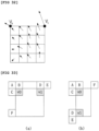
- the intra prediction mode may be derived independently for each of the luma component and the chroma component, or the intra prediction mode of the chroma component may be derived depending on the intra prediction mode of the luma component.
- the intra prediction mode of the chroma component may be determined based on the intra prediction mode of the luma component as shown in the following Table 1.
- intra_chroma_pred_mode means information signaled to specify the intra prediction mode of the chroma component
- IntraPredModeY indicates the intra prediction mode of the luma component.
- a reference sample for intra prediction of the current block may be derived at step S510.
- a reference sample for intra prediction may be derived based on a neighboring sample of the current block.
- the neighboring sample may be a reconstructed sample of the neighboring block, and the reconstructed sample may be a reconstructed sample before an in-loop filter is applied or a reconstructed sample after the in-loop filter is applied.
- a neighboring sample reconstructed before the current block may be used as the reference sample, and a neighboring sample filtered based on a predetermined intra filter may be used as the reference sample.
- the intra filter may include at least one of the first intra filter applied to multiple neighboring samples positioned on the same horizontal line and the second intra filter applied to multiple neighboring samples positioned on the same vertical line. Depending on the positions of the neighboring samples, one of the first intra filter and the second intra filter may be selectively applied, or both intra filters may be applied.
- Filtering may be adaptively performed based on at least one of the intra prediction mode of the current block and the size of the transform block for the current block. For example, when the intra prediction mode of the current block is the DC mode, the vertical mode, or the horizontal mode, filtering may not be performed. When the size of the transform block is NxM, filtering may not be performed. Here, N and M may be the same values or different values, or may be values of 4, 8, 16, or more. Alternatively, filtering may be selectively performed based on the result of a comparison of a pre-defined threshold and the difference between the intra prediction mode of the current block and the vertical mode (or the horizontal mode). For example, when the difference between the intra prediction mode of the current block and the vertical mode is greater than a threshold, filtering may be performed.
- the threshold may be defined for each size of the transform block as shown in Table 2. [Table 2] 8x8 transform 16x16 transform 32x32 transform Threshold 7 1 0
- the intra filter may be determined as one of multiple intra filter candidates pre-defined in the device for encoding/decoding a video. To this end, an index specifying an intra filter of the current block among the multiple intra filter candidates may be signaled. Alternatively, the intra filter may be determined based on at least one of the size/shape of the current block, the size/shape of the transform block, information on the filter strength, and variations of the neighboring samples.
- intra prediction may be performed using the intra prediction mode of the current block and the reference sample at step S520.
- the prediction sample of the current block may be obtained using the intra prediction mode determined at step S500 and the reference sample derived at step S510.
- a boundary sample of the neighboring block may be used, and thus quality of the prediction picture may be decreased. Therefore, a correction process may be performed on the prediction sample generated through the above-described prediction process, and will be described in detail with reference to FIGs. 6 to 15 .
- the correction process is not limited to being applied only to the intra prediction sample, and may be applied to an inter prediction sample or the reconstructed sample.
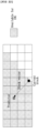
- FIG. 6 is a view illustrating a method of correcting a prediction sample of a current block based on differential information of neighboring samples according to an embodiment of the present invention.
- the prediction sample of the current block may be corrected based on the differential information of multiple neighboring samples for the current block.
- the correction may be performed on all prediction samples in the current block, or may be performed on prediction samples in some predetermined regions. Some regions may be one row/column or multiple rows/columns, or may be preset regions for correction in the device for encoding/decoding a video, or may be variably determined based on at least one of the size/shape of the current block and the intra prediction mode.
- the neighboring samples may belong to the neighboring blocks positioned at the top, the left, and the top left corner of the current block.
- the number of neighboring samples used for correction may be two, three, four, or more.
- the positions of the neighboring samples may be variably determined depending on the position of the prediction sample which is the correction target in the current block. Alternatively, some of the neighboring samples may have fixed positions regardless of the position of the prediction sample which is the correction target, and the remaining neighboring samples may have variable positions depending on the position of the prediction sample which is the correction target.
- the differential information of the neighboring samples may mean a differential sample between the neighboring samples, or may mean a value obtained by scaling the differential sample by a predetermined constant value (e.g., one, two, three, etc.).
- a predetermined constant value e.g., one, two, three, etc.
- the predetermined constant value may be determined considering the position of the prediction sample which is the correction target, the position of the column or row including the prediction sample which is the correction target, the position of the prediction sample within the column or row, etc.
- differential samples between the top left neighboring sample p(-1, -1) and neighboring samples p (-1, y) adjacent to the left boundary of the current block may be used to obtain the final prediction sample as shown in Equation 1.
- P ′ 0 y P 0 y + p ⁇ 1 , y ⁇ p ⁇ 1 , ⁇ 1 ⁇ 1
- differential samples between the top left neighboring sample p(-1, -1) and neighboring samples p(x, -1) adjacent to the top boundary of the current block may be used to obtain the final prediction sample as shown in Equation 2.
- P ′ x 0 p x 0 + p x , ⁇ 1 ⁇ p ⁇ 1 , ⁇ 1 ⁇ 1
- differential samples between the top left neighboring sample p(-1, -1) and neighboring samples p(-1, y) adjacent to the left boundary of the current block may be used to obtain the final prediction sample.
- the differential sample may be added to the prediction sample, or the differential sample may be scaled by a predetermined constant value, and then added to the prediction sample.
- the predetermined constant value used in scaling may be determined differently depending on the column and/or row.
- the intra prediction mode of the current block is the horizontal mode
- differential samples between the top left neighboring sample p(-1, -1) and neighboring samples p(x, -1) adjacent to the top boundary of the current block may be used to obtain the final prediction sample, as described in the case of the vertical mode.
- P ′ x 0 p x 0 + p x , ⁇ 1 ⁇ p ⁇ 1 , ⁇ 1 ⁇ 1
- P ′ x 1 p x 1 + p x , ⁇ 1 ⁇ p ⁇ 1 , ⁇ 1 ⁇ 2
- FIGs. 7 and 8 are views illustrating a method of correcting a prediction sample based on a predetermined correction filter according to an embodiment of the present invention.
- the prediction sample may be corrected based on the neighboring sample of the prediction sample which is the correction target and a predetermined correction filter.
- the neighboring sample may be specified by an angular line of the directional prediction mode of the current block, or may be at least one sample positioned on the same angular line as the prediction sample which is the correction target.
- the neighboring sample may be a prediction sample in the current block, or may be a reconstructed sample in a neighboring block reconstructed before the current block.
- At least one of the number of taps, strength, and a filter coefficient of the correction filter may be determined based on at least one of the position of the prediction sample which is the correction target, whether or not the prediction sample which is the correction target is positioned on the boundary of the current block, the intra prediction mode of the current block, angle of the directional prediction mode, the prediction mode (inter or intra mode) of the neighboring block, and the size/shape of the current block.
- the directional prediction mode has an index of 2 or 34
- at least one prediction/reconstructed sample positioned at the bottom left of the prediction sample which is the correction target and the predetermined correction filter may be used to obtain the final prediction sample.
- the prediction/reconstructed sample at the bottom left may belong to a previous line of a line including the prediction sample which is the correction target.
- the prediction/reconstructed sample at the bottom left may belong to the same block as the current sample, or to neighboring block adjacent to the current block.
- Filtering for the prediction sample may be performed only on the line positioned at the block boundary, or may be performed on multiple lines.
- the correction filter where at least one of the number of filter taps and a filter coefficient is different for each of lines may be used.
- a (1/2, 1/2) filter may be used for the left first line closest to the block boundary
- a (12/16, 4/16) filter may be used for the second line
- a (14/16, 2/16) filter may be used for the third line
- a (15/16, 1/16) filter may be used for the fourth line.
- filtering may be performed on the block boundary as shown in FIG. 8 , and a 3-tap correction filter may be used to correct the prediction sample. Filtering may be performed using the bottom left sample of the prediction sample which is the correction target, the bottom sample of the bottom left sample, and a 3-tap correction filter that takes as input the prediction sample which is the correction target.
- the position of neighboring sample used by the correction filter may be determined differently based on the directional prediction mode.
- the filter coefficient of the correction filter may be determined differently depending on the directional prediction mode.
- Different correction filters may be applied depending on whether the neighboring block is encoded in the inter mode or the intra mode.
- a filtering method where more weight is given to the prediction sample may be used, compared to when the neighboring block is encoded in the inter mode.
- the intra prediction mode is 34
- a (1/2, 1/2) filter may be used
- a (4/16, 12/16) filter may be used.
- the number of lines to be filtered in the current block may vary depending on the size/shape of the current block (e.g., the coding block or the prediction block). For example, when the size of the current block is equal to or less than 32x32, filtering may be performed on only one line at the block boundary; otherwise, filtering may be performed on multiple lines including the one line at the block boundary.
- FIGs. 7 and 8 are based on the case where the 35 intra prediction modes in FIG. 4 are used, but may be equally/similarly applied to the case where the extended intra prediction modes are used.
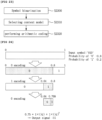
- FIG. 9 is a view illustrating a method of correcting a prediction sample using weight and offset according to an embodiment of the present invention.
- a weight and an offset for brightness compensation may be applied to the prediction sample such that quality of the prediction picture can be enhanced.
- At least one of a weight w and an offset f may be determined at step S900.
- At least one of the weight w and offset f may be signaled in at least one of a sequence parameter set, a picture parameter set, and a slice header.
- at least one of the weight w and offset f may be signaled in a predetermined block unit, and multiple blocks (e.g., the CU, the PU, and the TU) included in the predetermined block unit may share one signaled weight w and/or offset f.
- At least one of the weight w and offset f may be signaled regardless of the prediction mode of the current block, or may be signaled selectively considering the prediction mode.
- the prediction mode of the current block is the inter mode
- the weight w and/or offset f may be signaled; otherwise, it may not be signaled.
- the inter mode may include at least one of the skip mode, the merge mode, the AMVP mode, and the current picture reference mode.
- the current picture reference mode may mean a prediction mode using a pre-reconstructed region in the current picture including the current block.
- a motion vector for the current picture reference mode may be used to specify the pre-reconstructed region.
- a flag or index indicating whether the current block is encoded in the current picture reference mode may be signaled, or may be derived through a reference picture index of the current block.
- the current picture may be variably positioned in the reference picture list, and to this end, a separate reference picture index indicating the position of the current picture may be signaled.
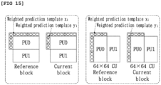
- the weight may be derived using brightness change between the first template in a particular shape adjacent to the current block and the second template corresponding thereto adjacent to the previous block.
- the second template may include an unavailable sample.
- an available sample may be copied to the position of the unavailable sample, or the available sample may be used which is derived through interpolation between multiple available samples.
- the available sample may be included in the second template or the neighboring block.
- At least one of the coefficient, the shape, and the number of taps of the filter used in interpolation may be determined variably based on the size and/or shape of the template. A method of composing a template will be described in detail with reference to FIGs. 10 to 15 .
- the weight w and offset f may be derived as follows.
- the weight w and offset f may be derived by obtaining the minimum value of E(w, f) in Equation 7.
- E w f ⁇ i p i ⁇ wp i ⁇ f 2 + ⁇ w ⁇ 1 2
- Equation 7 for obtaining the minimum value may be changed to Equation 8.
- ⁇ i x i x i + ⁇ ⁇ i x i ⁇ i x i ⁇ i 1 w f ⁇ i x i y i + ⁇ ⁇ i y i
- Equation 9 for deriving the weight w and Equation 10 for deriving the offset f may be obtained from Equation 8.
- At least one of the weight and offset determined at step S900 may be used to correct the prediction sample.
- the weight w and offset f are applied to the prediction sample p generated through intra prediction such that a corrected prediction sample p' may be obtained as shown in Equation 11.
- p ′ w ⁇ p + f
- the weight w and offset f may be applied to the prediction sample generated through inter prediction, or may be applied to the reconstructed sample.
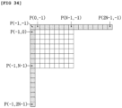
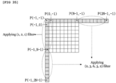
- FIGs. 10 to 15 are views illustrating a method of composing a template to determine weight w according to an embodiment of the present invention.
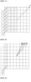
- a template may be composed of all neighboring samples adjacent to the current block, or a template may be composed of some samples sub-sampled from the neighboring samples adjacent to the current block.
- the middle of FIG. 10 shows an example of 1/2 sub-sampling, and a template may be composed of only samples in gray. Instead of 1/2 sub-sampling, the template may be composed using 1/4 sub-sampling or 1/8 sub-sampling.
- a template may be composed of all neighboring samples adjacent to the current block except for the sample positioned at the top left.
- a template composed of only the samples positioned on the left or a template composed of only the samples positioned at the top may be used.
- the template may be composed by increasing the number of neighboring samples. That is, the template in FIG. 11 may be composed of the first neighboring samples adjacent to the boundary of the current block and the second neighboring samples adjacent to the first neighboring samples.
- a template may be composed of all neighboring samples belonging to two lines adjacent to the boundary of the current block, or as shown in the middle of FIG. 11 , a template may be composed by sub-sampling the template in the left. As shown in the right of FIG. 11 , a template may be composed excluding four samples belonging to the top left. Not shown in FIG. 11 , considering the position of the current block in the picture or a coding tree block (largest coding unit), a template composed of only the samples positioned on the left or a template composed of only the samples positioned at the top may be used.
- different templates may be composed depending on the size and/or shape of the current block (whether the current block has a square shape whether the current block is symmetrically partitioned).
- a sub-sampling rate of the template may be applied differently depending on the size of the current block. For example, as shown in the left of FIG. 12 , when the size of the block is equal to or less than 64x64, a 1/2 sub-sampled template may be composed. As shown in the right of FIG. 12 , when the size of the block is equal to or greater than 128x128, a 1/4 sub-sampled template may be composed.
- the template may be composed by increasing the number of neighboring samples adjacent to the current block depending on the size thereof.
- Multiple template candidates that can be used in a sequence or slice may be determined, and one of the multiple template candidates may be selectively used.
- the multiple template candidates may include templates which have a different shape and/or size from each other. Information on the shape and/or size of the template may be signaled in a sequence header or slice header.
- an index may be assigned to each template candidate.
- syntax type_weight_pred_template_idx may be encoded. The device for decoding a video may use the template candidate selectively based on the syntax type_weight_pred_template_idx.
- the template of the middle of FIG. 10 may be assigned to 0, the template of the right of FIG. 10 may be assigned to 1, the template of the middle of FIG. 11 may be assigned to 2, and the template of the right of FIG. 11 may be assigned to 3.
- the template used in the sequence may be signaled.
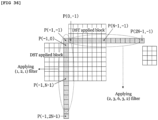
- the template When performing weighted prediction using a non-square block, the template may be composed by applying different sub-sampling rates to long and short sides such that the total number of templates is 2 ⁇ N. For example, as shown in FIG. 15 , the template may be composed by performing 1/2 sub-sampling on the short side and 1/4 sub-sampling on the long side.
- a generated prediction sample may not reflect the characteristics of an original picture since a range of reference samples being used is limited (e.g., intra prediction is performed only using the neighboring samples adjacent to the current block). For example, when an edge exists in a current block or when a new object appears around a boundary of the current block, a difference between a prediction sample and an original picture may be large depending on a position of a prediction sample in the current block.
- a residual value is relatively large, and thus the number of bits to be encoded/decoded may increase.
- a residual value in a region relatively far from a boundary of the current block may include a large amount of high-frequency components, which may result in degradation of encoding/decoding efficiency.
- a method of generating or updating a prediction sample in units of sub-block may be used. According to this, prediction accuracy in a region relatively far from a block boundary may be enhanced.
- a prediction sample generated based on a directional intra prediction mode is referred to as a first prediction sample.
- a prediction sample generated based on a non-directional intra prediction mode or a prediction sample generated by performing inter prediction may also be included in a category of the first prediction sample.
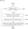
- FIG. 16 is a view illustrating a method of correcting a prediction sample based on an offset according to an embodiment of the present invention.
- step S1600 whether to update a first prediction sample using an offset may be determined at step S1600.
- Whether to update the first prediction sample using the offset may be determined by a flag decoded from a bitstream. For example, a syntax 'is_sub_block_refinement_flag' indicating whether to update the first prediction sample using the offset may be signaled through a bitstream.
- a value of is_sub_block_refinement_flag 1, the method of updating the first prediction sample using the offset may be used in the current block.
- step S1600 is intended to selectively perform updating of the first prediction sample, and is not an essential configuration for achieving the purpose of the present invention, so that step S1600 may be omitted in some cases.
- an intra prediction pattern of the current block may be determined at step S1610. Through the intra prediction pattern, all or some regions of the current block to which the offset is applied, a partition type of the current block, whether to apply the offset to a sub-block included in the current block, a size/sign of the offset assigned to each sub-block, etc. may be determined.
- One of multiple patterns pre-defined in the device for encoding/decoding a video may be selectively used as the intra prediction pattern of the current block, and to this end, an index specifying the intra prediction pattern of the current block may be signaled from a bitstream.
- the intra prediction pattern of the current block may be determined based on a partition mode of a prediction unit or a coding unit of the current block, a size/shape of the block, whether the directional intra prediction mode is used, an angle of the directional intra prediction mode, etc.
- the intra prediction pattern of the current block may be determined based on an index decoded from a bitstream.
- the flag information may be signaled in at least one of a picture level, a slice level, and a block level.
- the intra prediction pattern of the current block may be determined based on the partition mode of the prediction unit or the coding unit of the current block, etc. For example, the pattern in which the current block is partitioned into sub-blocks may be the same as the pattern in which the coding block is partitioned into prediction units.
- the offset may be obtained in units of sub-block at step S1620.
- the offset may be signaled in units of a slice, a coding unit, or a prediction unit.
- the offset may be derived from a neighboring sample of the current block.
- the offset may include at least one of offset value information and offset sign information.
- the offset value information may be in a range of integers equal to or greater than zero.
- a second prediction sample may be obtained for each sub-block at step S1630.
- the second prediction sample may be obtained by applying the offset to the first prediction sample.
- the second prediction sample may be obtained adding or subtracting the offset to or from the first prediction sample.
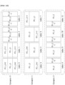
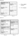
- FIGs. 17 to 21 are views illustrating examples of an intra prediction pattern of a current block according to an embodiment of the present invention.
- the current block when the index is '0' or '1', the current block may be partitioned into upper and lower sub-blocks.
- the offset may be not set to the upper sub-block, and the offset 'f' may be set to the lower sub-block. Therefore, the first prediction sample(P(i,j)) may be used as it is in the upper sub-block, and the second prediction sample(P(i,j)+f or P(i,j)-f) that is generated by adding or subtracting the offset to or from the first prediction sample may be used in the lower sub-block.
- 'not set' may mean that the offset is not assigned to the block, or the offset having the value of '0' may be assigned to the block.
- the current block is partitioned into left and right sub-blocks.
- the offset may not be set for the left sub-block, and the offset 'f' may be set for the right sub-block. Therefore, the first prediction sample(P(i,j)) may be used as it is in the left sub-block, and the second prediction sample(P(i,j)+f or P(i,j)-f) that is generated adding or subtracting the offset to or from the first prediction sample may be used in the right sub-block.
- the range of available intra prediction patterns may be limited based on the intra prediction mode of the current block. For example, when the intra prediction mode of the current block is a vertical direction intra prediction mode or a prediction mode in a direction similar to the vertical direction intra prediction mode (e.g., among the 33 directional prediction modes, when the intra prediction mode has an index of 22 to 30), only the intra prediction pattern partitioning the current block in a horizontal direction (e.g., the index 0 or index 1 in FIG. 17 ) may be applied to the current block.
- the intra prediction mode of the current block is a horizontal direction intra prediction mode or a prediction mode in a direction similar to the horizontal direction intra prediction mode (e.g., among the 33 directional prediction modes, when the intra prediction mode has an index of 6 to 14)
- only the intra prediction pattern partitioning the current block in a vertical direction e.g., the index 2 or index 3 in FIG. 17 ) may be applied to the current block.
- the offset is not set for one of the sub-blocks included in the current block, but it is set for the other. Whether to set the offset for the sub-block may be determined based on information signaled for each sub-block.
- Whether to set the offset for the sub-block may be determined based on a position of the sub-block, an index for identifying the sub-block in the current block, etc. For example, based on a predetermined boundary of the current block, the offset may not set for the sub-block which adjacent to the predetermined boundary, and the offset may be set for the sub-block which is not adjacent to the predetermined boundary.
- the offset When assuming that the predetermined boundary is the top boundary of the current block, under the intra prediction pattern corresponding to the index '0' or '1', the offset may be not set for the sub-block which is adjacent to the top boundary of the current block, and the offset may be set for the sub-block which is not adjacent to the top boundary of the current block.
- the offset may not be set for the sub-block which is adjacent to the left boundary of the current block, and the offset may be set for the sub-block which is not adjacent to the left boundary of the current block.
- the offset is not set for the one of the sub-blocks included in the current block but the offset is set for another one.
- different values of the offset may be set for the sub-blocks included in the current block.
- the offset 'h' may be set for the upper sub-block of the current block
- the offset 'f' may be set for the lower sub-block of the current block. Therefore, the second prediction sample (P(i,j)+h or P(i,j)-h) may be generated by adding or subtracting the offset 'h' to or from the first prediction sample in the upper sub-block, , and the second prediction sample(P(i,j)+f or P(i,j)-f) may be generated by adding or subtracting the offset 'f' to or from the first prediction sample.
- the offset 'h' may be set for the left sub-block of the current block
- the offset 'f' may be set for the right sub-block of the current block. Therefore, the second prediction sample(P(i,j)+h or P(i,j)-h) may be generated by adding or subtracting the offset 'h' to or from the first prediction sample may in the left sub-block, and the second prediction sample(P(i,j)+f or P(i,j)-f) may be generated by adding or subtracting the offset 'f' to or from the first prediction sample in the right sub-block.
- the current block is partitioned into two sub-blocks having the same size, but the number of sub-blocks and/or the size of sub-blocks included in the current block is not limited to the examples shown in FIGs. 17 and 18 .
- the number of sub-blocks included in the current block may be three or more, and the sub-blocks may have different sizes.
- the available intra prediction patterns may be grouped into multiple categories.
- the intra prediction pattern of the current block may be selected based on a first index for identifying a category and a second index identifying an intra prediction pattern in the category.
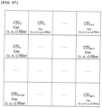
- intra prediction patterns may be classified into three categories each including four intra prediction patterns. For example, intra prediction patterns corresponding to indexes 0 to 3 may be classified as a category 0, intra prediction patterns corresponding to indexes 4 to 7 may be classified as a category 1, and intra prediction patterns corresponding to indexes 8 to 11 may be classified as a category 2.
- the device for decoding a video may decode the first index from a bitstream in order to specify the category including at least one intra prediction pattern.
- the first index may specify one of the categories 0, 1, and 2.
- the intra prediction pattern of the current block may be determined based on the second index decoded from a bitstream.
- the second index may specify one of the four intra prediction patterns (i.e., the index 4 to index 7) of the category 1.
- FIG. 19 it shows that categories include the same numbers of intra prediction patterns. But there is no need to the categories include the same numbers of intra prediction patterns.
- the number of available intra prediction patterns or of the number of categories may be determined in units of a sequence or a slice. Also, at least one of the number of available intra prediction patterns and the number of categories may be signaled through a sequence header or a slice header.
- the number of available intra prediction patterns and/or the number of categories may be determined based on a size of a prediction unit or a coding unit of the current block. For example, when the size of the current block (e.g., the coding unit of the current block) is equal to or greater than 64x64, the intra prediction pattern of the current block may be selected from five intra prediction patterns shown in FIG. 20 . In contrast, when the size of the current block (e.g., the coding unit of the current block) is less than 64x64, the intra prediction pattern of the current block may be selected from intra prediction patterns shown in FIG. 17, 18 , or 19 .
- each intra prediction pattern has a rectangular shape.
- the intra prediction pattern where at least one of the sizes and shapes of the sub-blocks are different from each other may be used.
- FIG. 22 is a view illustrating an example of an intra prediction pattern with different sizes and shapes of sub-blocks.
- the offset for each sub-block (e.g., the offset h, f, g, or i of each sub-block shown in FIGs. 17 to 21 ) may be decoded from a bitstream, or may be derived from the neighboring sample adjacent to the current block.
- the offset of the sub-block may be determined considering the distance from a sample at a particular position in the current block.
- the offset may be determined in proportion to a value representing the distance between a sample at a predetermined position in the current block and a sample at a predetermined position in the sub-block.
- the offset of the sub-block may be determined adding or subtracting a value determined based on the distance between a sample at a predetermined position in the current block and a sample at a predetermined position in the sub-block to or from a pre-set value.
- the offset may be determined based on a ratio of a value representing the size of the current block and a value representing the distance between a sample at a predetermined position in the current block and a sample at a predetermined position in the sub-block.
- the sample at the predetermined position in the current block may include a sample adjacent to the left boundary of the current block, a sample positioned at the top boundary of the current block, a sample adjacent to the top left corner of the current block, etc.
- FIG. 22 is a view illustrating a method of performing prediction using an intra block copy scheme according to an embodiment of the present invention.
- Intra block copy is a method where a current block is predicted/reconstructed using a block (hereinafter, referred to as 'a reference block') already reconstructed in the same picture as the current block. If a picture contains a large number of letters, such as Korean alphabet, an alphabet, etc. and a letter which is contained in the current block when the current block is reconstructed are contained in an already decoded block, intra block copy can enhance an encoding/decoding performance.
- An intra block copy method may be classified as an intra prediction method or an inter prediction method.
- an intra prediction mode for the intra block copy method may be defined.
- a bitstream may include a flag indicating whether to apply the intra block copy method to the current block.
- whether the current block uses intra block copy may be confirmed through a reference picture index of the current block. That is, when the reference picture index of the current block indicates the current picture, inter prediction may be performed on the current block using intra block copy. To this end, a pre-reconstructed current picture may be added to a reference picture list for the current block.
- the current picture may exist at a fixed position in the reference picture list (e.g., a position with the reference picture index of 0 or the last position).
- the current picture may have a variable position in the reference picture list, and to this end, a reference picture index indicating a position of the current picture may be signaled, separately.
- a position difference between the current block and the reference block may be defined as a motion vector (hereinafter, referred to as a block vector).
- the block vector may be derived by a sum of a prediction block vector and a differential block vector.
- the device for encoding a video may generate a prediction block vector through predictive coding, and may encode the differential block vector indicating the difference between the block vector and the prediction block vector.
- the device for decoding a video may derive the block vector of the current block by using the prediction block vector derived using pre-decoded information and the differential block vector decoded from a bitstream.
- the prediction block vector may be derived based on the block vector of a neighboring block adjacent to the current block, the block vector in an LCU of the current block, the block vector in an LCU row/column of the current block, etc.
- the device for encoding a video may generate a bitstream by performing binarizaton on a symbol, such as a transform coefficient, a motion vector difference, a syntax in a slice, etc., and performing arithmetic coding on binary values.
- a context may be determined considering the value of the same symbol of the neighboring block, information on the neighboring block, the position of the current block, etc.
- the occurrence probability of the symbol may be determined based on the determined probability index.
- the compression performance of the symbol can be enhanced through cumulative statistics of internal symbols, the occurrence probability recalculated based on the value of the encoded symbol, and arithmetic coding.
- CABAC may be used as an example of the arithmetic coding method.
- FIG. 23 is a flowchart illustrating a process of encoding a symbol.
- the device for encoding a video may binarize the symbol at step S2300.
- the device for encoding a video may convert the symbol to a binary symbol.
- the device for encoding a video may binarize a non-binary symbol, such as a transform coefficient, a motion vector difference, etc., to a binary symbol consisting of the values of 0 and 1.
- the symbol is binarized, among mapped codewords, the bit having '0' or '1' may be referred to as a bin.
- Symbol binarization may be performed through Unary binarization, truncated unary binarization, etc.
- Table 3 shows a unary binarization method
- Table 4 shows a truncated unary binarization method when the maximum bit length (cMax) is six.
- cMax maximum bit length
- a context model is selected at step S2310.
- the context model represents a probability model for each symbol.
- the occurrence probability of 0 or 1 in the bin may differ for each context model.
- the occurrence probability of the symbol may indicate the occurrence probability of 0 or 1 in the bin.
- HEVC HEVC, about 400 independent contexts for various symbols exist.
- the probability index (pStateIdx) for each context may be initialized based on at least one of the quantization parameter (Qp) and the slice type (I, P, or B).
- the probability index for each context may be initialized based on at least one of the quantization parameter (Qp) and the slice type (I, P, or B).
- the interval [0, 0.8) may be updated to [0.64, 0.8).
- the interval [0.64, 0.8) may be updated to [0.64, 0.768).
- a most probable symbol means a symbol having a high occurrence frequency between 0 and 1
- a least probable symbol means a symbol having a low occurrence frequency between 0 and 1.
- Occurrence probability initial values of the MPS and LPS may be determined based on the context and the quantization parameter (Qp) value.
- an MPS probability value of the symbol may increase while an LPS probability value may decrease.
- the MPS probability value of the symbol may decrease while the LPS probability value may increase.
- MPS occurrence probabilities and LPS occurrence probabilities are defined, but a smaller or greater number of MPS occurrence probabilities or LPS occurrence probabilities may be defined and used.
- the MPS occurrence probabilities and LPS occurrence probabilities may be specified by an index (pStateIdx) indicating the occurrence probability of the symbol. When the value of the index indicating the occurrence probability of the symbol is large, the occurrence probability of the MPS is high.
- Table 5 is intended to explain an example of updating a probability index (pStateIdx).
- pStateIdx 0 1 2 3 4 5 6 7 8 9 10 11 12 13 14 15 transIdxLPS 0 0 1 2 2 4 4 5 6 7 8 9 9 11 11 12 transIdxMPS 1 2 3 4 5 6 7 8 9 10 11 12 13 14 15 16 pStateIdx 16 17 18 19 20 21 22 23 24 25 26 27 28 29 30 31 transIdxLPS 13 13 15 15 16 16 18 18 19 19 21 21 22 22 23 24 transIdxMPS 17 18 19 20 21 22 23 24 25 26 27 28 29 30 31 32 pStateIdx 32 33 34 35 36 37 38 39 40 41 42 43 44 45 46 47 transIdxLPS 24 25 26 26 27 27 28 29 30 30 30 31 21 32 33 transIdxMPS 33 34 35 36 37 38 39 40 41 42 43 44 45 46 47 transIdxLPS 24 25 26 26 27 27 28 29 29 30 30 30 31 21 32 33 transIdxMPS
- a probability index (pStateIdx) indicating the probability value of the current context may be updated to an index corresponding to transIdxMPS. For example, when the value of pStateIdx is 16 and the MPS is encoded, pStateIdx may be updated to the index 17 corresponding to transIdxMPS. In contrast, when the value of pStateIdx is 16 and the LPS is encoded, pStateIdx may be updated to the index 13 corresponding to transIdxLPS. When pStateIdx is updated, the occurrence probabilities of the MPS and LPS may be updated.
- the occurrence probability of the MPS is 0.5.
- the frequency of the LPS may increase compared to the MPS. Therefore, when the value of pStateIdx is 0 and the LPS is encoded, the MPS and the LPS may be interchanged with each other.
- the value of the probability index for each context may be initialized in units of a slice or a tile. Since the probability index is initialized in slice units, the current slice may be decoded regardless of whether the previous slice or the previous frame is encoded. However, when the symbol is encoded using an initialized probability index, the probability specified by the initialized probability index does not properly reflect the actual occurrence probability of the symbol, and thus initial encoding efficiency of the slice may be decreased.
- the probability index accumulated at a predetermined point during encoding/decoding the previous slice may be set to an initial value of the probability index of the current slice.
- the predetermined point may indicate a start point of encoding/decoding a block positioned at a particular position (e.g., the middle position) in the slice in scan order.
- the probability value or probability index accumulated in the previous slice may be directly encoded/decoded through the header of the current slice, etc.
- multiple probability indexes may be assigned to one context so as to determine the initial probability index of the slice differently. For example, when multiple probability indexes having different values exist for an arbitrary context (ctx), one of the multiple probability indexes may be determined as the initial probability index.
- information for selecting one of the multiple probability indexes may be signaled through the slice header, etc.
- the device for decoding a video may select the probability index through information transmitted from the slice header, and may performing decoding using the selected probability index as the initial probability index.
- multiple initial values may be assigned for one context so as to determine the initial probability index of the slice differently.
- variables m and n may be derived using the initial value and a variable preCtxState indicating the previous context condition may be derived through the derived variable m and n.
- the MPS and the context probability index initial value pStateIdx may be derived.
- Table 7 shows a process of deriving the probability index based on the initial value.
- m slopeIdx * 5 - 45
- n (offsetIdx ⁇ 3) -16
- pStateIdx valMps ( preCtxState - 64 ) : ( 63 - preCtxState ) (3)
- An index for specifying an initial value (InitValue) to be used in the slice may be signaled through the slice header.
- the index for specifying a context initial value may be defined as a CABAC initialization index (cabac_init_idx).
- CABAC initialization index cabac_init_idx
- an initial value corresponding to cabac_init_idx may be determined.
- a syntax indicating the number of available CABAC initialization indexes may be signaled through the slice header, the sequence header, the picture header, etc.
- the syntax indicating the number of available CABAC initialization indexes may be defined as 'num_cabac_init_idx_minus1'.
- Table 8 and Table 9 are charts to explain an example of determining the initial value based on the CABAC initialization index.
- Table 8 shows the case where the number of available CABAC initialization indexes are five, and Table 9 shows the case where the number of available CABAC initialization indexes are six.
- Table 8 or Table 9 may be selectively used based on the value of num_cabac_init_minus1.
Landscapes
- Engineering & Computer Science (AREA)
- Multimedia (AREA)
- Signal Processing (AREA)
- Compression Or Coding Systems Of Tv Signals (AREA)
- Picture Signal Circuits (AREA)
- Closed-Circuit Television Systems (AREA)
Applications Claiming Priority (4)
| Application Number | Priority Date | Filing Date | Title |
|---|---|---|---|
| KR1020160022481A KR102609632B1 (ko) | 2016-02-25 | 2016-02-25 | 비디오 신호 처리 방법 및 장치 |
| KR1020160022476A KR20170100211A (ko) | 2016-02-25 | 2016-02-25 | 비디오 신호 처리 방법 및 장치 |
| PCT/KR2017/002072 WO2017146526A1 (ko) | 2016-02-25 | 2017-02-24 | 비디오 신호 처리 방법 및 장치 |
| EP17756864.9A EP3422719B1 (de) | 2016-02-25 | 2017-02-24 | Videosignalverarbeitungsverfahren und -vorrichtung |
Related Parent Applications (1)
| Application Number | Title | Priority Date | Filing Date |
|---|---|---|---|
| EP17756864.9A Division EP3422719B1 (de) | 2016-02-25 | 2017-02-24 | Videosignalverarbeitungsverfahren und -vorrichtung |
Publications (2)
| Publication Number | Publication Date |
|---|---|
| EP4542999A2 true EP4542999A2 (de) | 2025-04-23 |
| EP4542999A3 EP4542999A3 (de) | 2025-07-02 |
Family
ID=59685482
Family Applications (2)
| Application Number | Title | Priority Date | Filing Date |
|---|---|---|---|
| EP25151170.5A Pending EP4542999A3 (de) | 2016-02-25 | 2017-02-24 | Verfahren und vorrichtung zur verarbeitung eines videosignals |
| EP17756864.9A Active EP3422719B1 (de) | 2016-02-25 | 2017-02-24 | Videosignalverarbeitungsverfahren und -vorrichtung |
Family Applications After (1)
| Application Number | Title | Priority Date | Filing Date |
|---|---|---|---|
| EP17756864.9A Active EP3422719B1 (de) | 2016-02-25 | 2017-02-24 | Videosignalverarbeitungsverfahren und -vorrichtung |
Country Status (6)
| Country | Link |
|---|---|
| US (1) | US20190068989A1 (de) |
| EP (2) | EP4542999A3 (de) |
| CN (4) | CN117376553A (de) |
| ES (4) | ES2692864B1 (de) |
| PL (1) | PL3422719T3 (de) |
| WO (1) | WO2017146526A1 (de) |
Families Citing this family (34)
| Publication number | Priority date | Publication date | Assignee | Title |
|---|---|---|---|---|
| US11503315B2 (en) * | 2016-08-19 | 2022-11-15 | Lg Electronics Inc. | Method and apparatus for encoding and decoding video signal using intra prediction filtering |
| CN109804630A (zh) * | 2016-10-10 | 2019-05-24 | 夏普株式会社 | 对视频数据编码执行运动补偿的系统以及方法 |
| US10992939B2 (en) * | 2017-10-23 | 2021-04-27 | Google Llc | Directional intra-prediction coding |
| US10225578B2 (en) | 2017-05-09 | 2019-03-05 | Google Llc | Intra-prediction edge filtering |
| CN115460403A (zh) * | 2017-07-31 | 2022-12-09 | 韩国电子通信研究院 | 对图像编码和解码的方法及存储比特流的计算机可读介质 |
| WO2019143093A1 (ko) * | 2018-01-16 | 2019-07-25 | 삼성전자주식회사 | 비디오 복호화 방법 및 장치, 비디오 부호화 방법 및 장치 |
| RU2752011C1 (ru) | 2018-04-01 | 2021-07-21 | Б1 Инститьют Оф Имидж Текнолоджи, Инк. | Способ и оборудование для кодирования/декодирования изображения |
| US10986354B2 (en) * | 2018-04-16 | 2021-04-20 | Panasonic Intellectual Property Corporation Of America | Encoder, decoder, encoding method, and decoding method |
| WO2019229683A1 (en) | 2018-05-31 | 2019-12-05 | Beijing Bytedance Network Technology Co., Ltd. | Concept of interweaved prediction |
| WO2020002762A1 (en) * | 2018-06-28 | 2020-01-02 | Nokia Technologies Oy | Method and apparatus for motion compensation with non-square sub-blocks in video coding |
| BR112020025916A2 (pt) * | 2018-06-30 | 2021-03-16 | Guangdong Oppo Mobile Telecommunications Corp., Ltd. | Método para decodificar um sinal de vídeo |
| US10462488B1 (en) | 2018-07-13 | 2019-10-29 | Tencent America LLC | Method and apparatus for video coding |
| CN110944189B (zh) | 2018-09-23 | 2023-11-28 | 北京字节跳动网络技术有限公司 | 从仿射运动预测的非仿射块 |
| WO2020098813A1 (en) | 2018-11-16 | 2020-05-22 | Beijing Bytedance Network Technology Co., Ltd. | Usage for history-based affine parameters |
| WO2020098808A1 (en) * | 2018-11-17 | 2020-05-22 | Beijing Bytedance Network Technology Co., Ltd. | Construction of merge with motion vector difference candidates |
| CN117528076A (zh) * | 2018-11-22 | 2024-02-06 | 北京字节跳动网络技术有限公司 | 用于具有几何分割的帧间预测的构建方法 |
| EP3871410A4 (de) * | 2018-11-29 | 2021-12-22 | Beijing Bytedance Network Technology Co., Ltd. | Interaktion zwischen einem intrablockkopiermodus und interprädiktionstools |
| CN113170159B (zh) * | 2018-12-08 | 2022-09-27 | 北京字节跳动网络技术有限公司 | 对仿射参数的移位 |
| EP3868107A4 (de) | 2018-12-21 | 2021-12-15 | Beijing Bytedance Network Technology Co. Ltd. | Bewegungsvektorgenauigkeit in zusammenschaltung mit bewegungsvektordifferenzmodus |
| WO2020135465A1 (en) | 2018-12-28 | 2020-07-02 | Beijing Bytedance Network Technology Co., Ltd. | Modified history based motion prediction |
| CN113597760B (zh) | 2019-01-02 | 2024-08-16 | 北京字节跳动网络技术有限公司 | 视频处理的方法 |
| CN109818940B (zh) * | 2019-01-03 | 2021-06-25 | 浙江好络维医疗技术有限公司 | 一种适用于在嵌入式硬件中实现实时传输的心电波形快速压缩算法 |
| US11356699B2 (en) * | 2019-01-11 | 2022-06-07 | Hfi Innovation Inc. | Method and apparatus of sub-block deblocking in video coding |
| CN113439444B (zh) | 2019-02-02 | 2026-03-24 | 北京字节跳动网络技术有限公司 | 用于仿射的多hmvp |
| CN113491125B (zh) * | 2019-02-22 | 2025-01-10 | 北京字节跳动网络技术有限公司 | 基于历史的仿射模式子表 |
| WO2020181474A1 (zh) | 2019-03-11 | 2020-09-17 | Oppo广东移动通信有限公司 | 预测值的确定方法、编码器以及计算机存储介质 |
| US11178399B2 (en) * | 2019-03-12 | 2021-11-16 | Qualcomm Incorporated | Probability initialization for video coding |
| US11290722B2 (en) * | 2019-03-12 | 2022-03-29 | Tencent America LLC | Method and apparatus for video encoding or decoding |
| US12395638B2 (en) * | 2019-06-19 | 2025-08-19 | Electronics And Telecommunications Research Institute | Image encoding/decoding method and device, and recording medium for storing bitstream |
| CN111656782A (zh) * | 2019-06-19 | 2020-09-11 | 北京大学 | 视频处理方法和设备 |
| CN113905236B (zh) | 2019-09-24 | 2023-03-28 | Oppo广东移动通信有限公司 | 图像编解码方法、编码器、解码器以及存储介质 |
| US12003731B2 (en) | 2021-09-29 | 2024-06-04 | Qualcomm Incorporated | Adaptive determination of multiple transform candidates for video coding |
| US12445614B2 (en) * | 2022-02-07 | 2025-10-14 | Tencent America LLC | Adaptive context-based adaptive binary arithmetic coding (CABAC) initial state selection from coded pictures |
| US12425572B2 (en) * | 2022-10-20 | 2025-09-23 | Tencent America LLC | Local illumination compensation |
Family Cites Families (18)
| Publication number | Priority date | Publication date | Assignee | Title |
|---|---|---|---|---|
| JP3277111B2 (ja) * | 1995-10-18 | 2002-04-22 | シャープ株式会社 | 動画像符号化装置および動画像復号化装置 |
| AU1941797A (en) * | 1997-03-17 | 1998-10-12 | Mitsubishi Denki Kabushiki Kaisha | Image encoder, image decoder, image encoding method, image decoding method and image encoding/decoding system |
| US20090051679A1 (en) * | 2007-08-24 | 2009-02-26 | Simon Robinson | Local motion estimation using four-corner transforms |
| US8665958B2 (en) * | 2008-01-29 | 2014-03-04 | Electronics And Telecommunications Research Institute | Method and apparatus for encoding and decoding video signal using motion compensation based on affine transformation |
| US9008175B2 (en) * | 2010-10-01 | 2015-04-14 | Qualcomm Incorporated | Intra smoothing filter for video coding |
| US9584806B2 (en) * | 2012-04-19 | 2017-02-28 | Futurewei Technologies, Inc. | Using depth information to assist motion compensation-based video coding |
| WO2014065547A1 (ko) * | 2012-10-22 | 2014-05-01 | (주)휴맥스 | 3차원 영상의 뷰간(inter-view) 움직임 벡터 예측에서의 변이 벡터 유도 방법 |
| EP2920962A4 (de) * | 2012-11-13 | 2016-07-20 | Intel Corp | Inhaltsadaptive transformationscodierung für videos der nächsten generation |
| KR102121558B1 (ko) * | 2013-03-15 | 2020-06-10 | 삼성전자주식회사 | 비디오 이미지의 안정화 방법, 후처리 장치 및 이를 포함하는 비디오 디코더 |
| US9596448B2 (en) * | 2013-03-18 | 2017-03-14 | Qualcomm Incorporated | Simplifications on disparity vector derivation and motion vector prediction in 3D video coding |
| US9438910B1 (en) * | 2014-03-11 | 2016-09-06 | Google Inc. | Affine motion prediction in video coding |
| KR101589186B1 (ko) * | 2014-04-16 | 2016-01-27 | 국방과학연구소 | 글로벌 모션벡터 보상을 이용한 영상정합 방법 |
| CN112087630B (zh) * | 2014-09-30 | 2022-04-08 | 华为技术有限公司 | 图像预测方法、装置、解码器及存储介质 |
| CN104363451B (zh) * | 2014-10-27 | 2019-01-25 | 华为技术有限公司 | 图像预测方法及相关装置 |
| WO2016141609A1 (zh) * | 2015-03-10 | 2016-09-15 | 华为技术有限公司 | 图像预测方法和相关设备 |
| CN108600749B (zh) * | 2015-08-29 | 2021-12-28 | 华为技术有限公司 | 图像预测的方法及设备 |
| WO2017118409A1 (en) * | 2016-01-07 | 2017-07-13 | Mediatek Inc. | Method and apparatus for affine merge mode prediction for video coding system |
| WO2017130696A1 (ja) * | 2016-01-29 | 2017-08-03 | シャープ株式会社 | 予測画像生成装置、動画像復号装置、および動画像符号化装置 |
-
2017
- 2017-02-24 ES ES201890055A patent/ES2692864B1/es active Active
- 2017-02-24 ES ES201900064A patent/ES2737841B1/es active Active
- 2017-02-24 CN CN202311295084.1A patent/CN117376553A/zh active Pending
- 2017-02-24 ES ES202130694A patent/ES2917099B1/es active Active
- 2017-02-24 PL PL17756864.9T patent/PL3422719T3/pl unknown
- 2017-02-24 CN CN202311295092.6A patent/CN117376554A/zh active Pending
- 2017-02-24 CN CN202311294163.0A patent/CN117354536A/zh active Pending
- 2017-02-24 CN CN201780012734.3A patent/CN108702509B/zh active Active
- 2017-02-24 EP EP25151170.5A patent/EP4542999A3/de active Pending
- 2017-02-24 EP EP17756864.9A patent/EP3422719B1/de active Active
- 2017-02-24 ES ES202030908A patent/ES2800509B1/es active Active
- 2017-02-24 US US16/080,005 patent/US20190068989A1/en not_active Abandoned
- 2017-02-24 WO PCT/KR2017/002072 patent/WO2017146526A1/ko not_active Ceased
Also Published As
| Publication number | Publication date |
|---|---|
| EP3422719A1 (de) | 2019-01-02 |
| ES2917099B1 (es) | 2023-04-21 |
| EP4542999A3 (de) | 2025-07-02 |
| ES2692864R1 (es) | 2019-01-02 |
| EP3422719B1 (de) | 2025-01-15 |
| ES2692864B1 (es) | 2019-10-21 |
| CN117354536A (zh) | 2024-01-05 |
| EP3422719C0 (de) | 2025-01-15 |
| ES2800509R1 (es) | 2021-03-02 |
| ES2917099A2 (es) | 2022-07-06 |
| ES2737841B1 (es) | 2021-07-27 |
| ES2737841R1 (es) | 2020-04-16 |
| CN117376554A (zh) | 2024-01-09 |
| ES2800509A2 (es) | 2020-12-30 |
| CN108702509A (zh) | 2018-10-23 |
| ES2692864A2 (es) | 2018-12-05 |
| ES2917099R1 (es) | 2022-08-05 |
| CN117376553A (zh) | 2024-01-09 |
| EP3422719A4 (de) | 2019-10-09 |
| US20190068989A1 (en) | 2019-02-28 |
| WO2017146526A1 (ko) | 2017-08-31 |
| PL3422719T3 (pl) | 2025-03-24 |
| ES2737841A2 (es) | 2020-01-16 |
| ES2800509B1 (es) | 2021-12-21 |
| CN108702509B (zh) | 2023-10-31 |
Similar Documents
| Publication | Publication Date | Title |
|---|---|---|
| EP3422719B1 (de) | Videosignalverarbeitungsverfahren und -vorrichtung | |
| US20250039359A1 (en) | Method and device for processing video signal | |
| US11343499B2 (en) | Method and apparatus for processing video signal | |
| US20230412838A1 (en) | Method and apparatus for processing video signal | |
| US20230328277A1 (en) | Method and apparatus for processing video signal | |
| EP3477950B1 (de) | Inraprädiktion unter verwendung von referenzpixel aus zusätzlichen pixellinien | |
| EP3343926A1 (de) | Verfahren und vorrichtung zur verarbeitung eines videosignals | |
| EP3518535A1 (de) | Verfahren und vorrichtung zur verarbeitung eines videosignals | |
| EP3509307A1 (de) | Verfahren und vorrichtung zur verarbeitung eines videosignals | |
| KR102609632B1 (ko) | 비디오 신호 처리 방법 및 장치 |
Legal Events
| Date | Code | Title | Description |
|---|---|---|---|
| PUAI | Public reference made under article 153(3) epc to a published international application that has entered the european phase |
Free format text: ORIGINAL CODE: 0009012 |
|
| STAA | Information on the status of an ep patent application or granted ep patent |
Free format text: STATUS: THE APPLICATION HAS BEEN PUBLISHED |
|
| AC | Divisional application: reference to earlier application |
Ref document number: 3422719 Country of ref document: EP Kind code of ref document: P |
|
| AK | Designated contracting states |
Kind code of ref document: A2 Designated state(s): AL AT BE BG CH CY CZ DE DK EE ES FI FR GB GR HR HU IE IS IT LI LT LU LV MC MK MT NL NO PL PT RO RS SE SI SK SM TR |
|
| REG | Reference to a national code |
Ref country code: DE Ref legal event code: R079 Free format text: PREVIOUS MAIN CLASS: H04N0019540000 Ipc: H04N0019513000 |
|
| PUAL | Search report despatched |
Free format text: ORIGINAL CODE: 0009013 |
|
| AK | Designated contracting states |
Kind code of ref document: A3 Designated state(s): AL AT BE BG CH CY CZ DE DK EE ES FI FR GB GR HR HU IE IS IT LI LT LU LV MC MK MT NL NO PL PT RO RS SE SI SK SM TR |
|
| RIC1 | Information provided on ipc code assigned before grant |
Ipc: H04N 19/54 20140101ALI20250527BHEP Ipc: H04N 19/537 20140101ALI20250527BHEP Ipc: H04N 19/176 20140101ALI20250527BHEP Ipc: H04N 19/593 20140101ALI20250527BHEP Ipc: H04N 19/513 20140101AFI20250527BHEP |
|
| STAA | Information on the status of an ep patent application or granted ep patent |
Free format text: STATUS: REQUEST FOR EXAMINATION WAS MADE |
|
| 17P | Request for examination filed |
Effective date: 20251230 |