EP4542997A1 - Verfahren zur kompensation lokaler beleuchtung, videocodierungsverfahren, videodecodierungsverfahren, vorrichtungen und system - Google Patents
Verfahren zur kompensation lokaler beleuchtung, videocodierungsverfahren, videodecodierungsverfahren, vorrichtungen und system Download PDFInfo
- Publication number
- EP4542997A1 EP4542997A1 EP22947130.5A EP22947130A EP4542997A1 EP 4542997 A1 EP4542997 A1 EP 4542997A1 EP 22947130 A EP22947130 A EP 22947130A EP 4542997 A1 EP4542997 A1 EP 4542997A1
- Authority
- EP
- European Patent Office
- Prior art keywords
- lic
- mode
- current block
- reconstructed samples
- neighbouring reconstructed
- Prior art date
- Legal status (The legal status is an assumption and is not a legal conclusion. Google has not performed a legal analysis and makes no representation as to the accuracy of the status listed.)
- Pending
Links
Images


Classifications
-
- H—ELECTRICITY
- H04—ELECTRIC COMMUNICATION TECHNIQUE
- H04N—PICTORIAL COMMUNICATION, e.g. TELEVISION
- H04N19/00—Methods or arrangements for coding, decoding, compressing or decompressing digital video signals
- H04N19/10—Methods or arrangements for coding, decoding, compressing or decompressing digital video signals using adaptive coding
- H04N19/134—Methods or arrangements for coding, decoding, compressing or decompressing digital video signals using adaptive coding characterised by the element, parameter or criterion affecting or controlling the adaptive coding
- H04N19/146—Data rate or code amount at the encoder output
- H04N19/147—Data rate or code amount at the encoder output according to rate distortion criteria
-
- H—ELECTRICITY
- H04—ELECTRIC COMMUNICATION TECHNIQUE
- H04N—PICTORIAL COMMUNICATION, e.g. TELEVISION
- H04N19/00—Methods or arrangements for coding, decoding, compressing or decompressing digital video signals
- H04N19/10—Methods or arrangements for coding, decoding, compressing or decompressing digital video signals using adaptive coding
- H04N19/102—Methods or arrangements for coding, decoding, compressing or decompressing digital video signals using adaptive coding characterised by the element, parameter or selection affected or controlled by the adaptive coding
- H04N19/103—Selection of coding mode or of prediction mode
- H04N19/105—Selection of the reference unit for prediction within a chosen coding or prediction mode, e.g. adaptive choice of position and number of pixels used for prediction
-
- H—ELECTRICITY
- H04—ELECTRIC COMMUNICATION TECHNIQUE
- H04N—PICTORIAL COMMUNICATION, e.g. TELEVISION
- H04N19/00—Methods or arrangements for coding, decoding, compressing or decompressing digital video signals
- H04N19/10—Methods or arrangements for coding, decoding, compressing or decompressing digital video signals using adaptive coding
- H04N19/134—Methods or arrangements for coding, decoding, compressing or decompressing digital video signals using adaptive coding characterised by the element, parameter or criterion affecting or controlling the adaptive coding
- H04N19/157—Assigned coding mode, i.e. the coding mode being predefined or preselected to be further used for selection of another element or parameter
- H04N19/159—Prediction type, e.g. intra-frame, inter-frame or bidirectional frame prediction
-
- H—ELECTRICITY
- H04—ELECTRIC COMMUNICATION TECHNIQUE
- H04N—PICTORIAL COMMUNICATION, e.g. TELEVISION
- H04N19/00—Methods or arrangements for coding, decoding, compressing or decompressing digital video signals
- H04N19/10—Methods or arrangements for coding, decoding, compressing or decompressing digital video signals using adaptive coding
- H04N19/169—Methods or arrangements for coding, decoding, compressing or decompressing digital video signals using adaptive coding characterised by the coding unit, i.e. the structural portion or semantic portion of the video signal being the object or the subject of the adaptive coding
- H04N19/17—Methods or arrangements for coding, decoding, compressing or decompressing digital video signals using adaptive coding characterised by the coding unit, i.e. the structural portion or semantic portion of the video signal being the object or the subject of the adaptive coding the unit being an image region, e.g. an object
- H04N19/176—Methods or arrangements for coding, decoding, compressing or decompressing digital video signals using adaptive coding characterised by the coding unit, i.e. the structural portion or semantic portion of the video signal being the object or the subject of the adaptive coding the unit being an image region, e.g. an object the region being a block, e.g. a macroblock
-
- H—ELECTRICITY
- H04—ELECTRIC COMMUNICATION TECHNIQUE
- H04N—PICTORIAL COMMUNICATION, e.g. TELEVISION
- H04N19/00—Methods or arrangements for coding, decoding, compressing or decompressing digital video signals
- H04N19/50—Methods or arrangements for coding, decoding, compressing or decompressing digital video signals using predictive coding
- H04N19/503—Methods or arrangements for coding, decoding, compressing or decompressing digital video signals using predictive coding involving temporal prediction
- H04N19/51—Motion estimation or motion compensation
- H04N19/513—Processing of motion vectors
- H04N19/517—Processing of motion vectors by encoding
- H04N19/52—Processing of motion vectors by encoding by predictive encoding
-
- H—ELECTRICITY
- H04—ELECTRIC COMMUNICATION TECHNIQUE
- H04N—PICTORIAL COMMUNICATION, e.g. TELEVISION
- H04N19/00—Methods or arrangements for coding, decoding, compressing or decompressing digital video signals
- H04N19/70—Methods or arrangements for coding, decoding, compressing or decompressing digital video signals characterised by syntax aspects related to video coding, e.g. related to compression standards
Definitions
- Embodiments of the disclosure relate to, but not limited to, video technology, and more specifically, to a local illumination compensation (LIC) method, a video coding method, apparatus, and system.
- LIC local illumination compensation
- a block-based hybrid coding framework is adopted.
- Each picture in a video is partitioned into square largest coding units (LCU) of the same size (for example, 128 ⁇ 128 or 64 ⁇ 64).
- LCU square largest coding units
- Each LCU can be partitioned into rectangular coding units (CU) according to a certain rule.
- the CU may be further partitioned into prediction units (PU), transform units (TU), and the like.
- the hybrid coding framework includes modules such as prediction, transform, quantization, entropy coding, and an in-loop filter.
- the prediction module includes intra prediction and inter prediction.
- Inter prediction includes motion estimation and motion compensation.
- the methods and/or procedures may be presented as a particular sequence of steps in the specification. However, if the method or procedure does not depend on the particular order of steps described herein, the method or procedure shall not be limited to the particular order of steps described. It can be understood by those of ordinary skill in the art that other sequences of steps are also possible. Thus, the particular order of steps described in the specification shall not be construed as a limitation on the claims. In addition, the claims regarding the methods and/or procedures shall not be limited to implementing the steps in the described order. It can be understood by those of ordinary skill in the art that these orders can be changed without departing from the spirit and scope of embodiments of the disclosure.
- the local illumination compensation (LIC) method and the video coding method provided in embodiments of the disclosure can be applied to various video coding standards, such as H.264/advanced video coding (AVC), H.265/high efficiency video coding (HEVC), H.266/versatile video coding (VVC), audio video coding standard (AVS), and other standards proposed by moving picture experts group (MPEG), alliance for open media (AOM), and joint video experts team (JVET), as well as extensions of these standards, or any other customized standard, etc.
- AVC H.264/advanced video coding
- HEVC H.265/high efficiency video coding
- VVC high efficiency video coding
- VVC high efficiency video coding
- AOM alliance for open media
- JVET joint video experts team
- the encoding-end apparatus 1 includes a data source 11, a video encoding apparatus 13, and an output interface 15.
- the data source 11 may include a video capture apparatus (e.g., a camera), an archive containing previously captured data, a feeding interface for receiving data from a content provider, a computer graphics system for generating data, or a combination thereof.
- the video encoding apparatus 13 can encode data from the data source 11 and output the encoded data to the output interface 15.
- the output interface 15 can include at least one of a regulator, a modem, or a transmitter.
- the decoding-end apparatus 2 includes an input interface 21, a video decoding apparatus 23, and a display apparatus 25.
- the input interface 21 includes at least one of a receiver or a modem.
- the input interface 21 can receive the bitstream via the link 3 or from the storage apparatus.
- the video decoding apparatus 23 is configured to decode the received bitstream.
- the display apparatus 25 is configured to display the decoded data, and the display apparatus 25 can be integrated with other apparatuses of the decoding-end apparatus 2 or disposed separately.
- the decoding end may not include the display apparatus 25. In other examples, the decoding end may include other apparatuses or devices to which the decoded data is applicable.
- various video coding methods can be used for video compression and decompression.
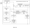
- FIG. 1B is a block diagram of an exemplary video encoding apparatus to which embodiments of the disclosure can be applied.
- the video encoding apparatus 1000 includes a prediction unit 1100, a partitioning unit 1101, a residual generation unit 1102 (which is represented by a circle with plus sign subsequent to the partitioning unit 1101), a transform processing unit 1104, a quantization unit 1106, an inverse quantization unit 1108, an inverse transform processing unit 1110, a reconstruction unit 1112 (which is represented by a circle with a plus sign subsequent to the inverse transform processing unit 1110), a filter unit 1113, a decoded picture buffer 1114, and an entropy coding unit 1115.
- the prediction unit 1100 includes an inter prediction unit 1121 and an intra prediction unit 1126.
- the decoded picture buffer 1114 can also be referred to as a buffer for decoded picture, etc.
- the video encoder 20 can also include more, fewer, or different functional components than those in the example.
- the transform processing unit 1104 and the inverse transform processing unit 1110 can be eliminated in some cases.
- the partitioning unit 1101 is configured to partition, in cooperation with the prediction unit 1100, received video data into slices, coding tree units (CTU), or other larger units.
- the video data received by the partitioning unit 1101 can be a video sequence of video frames such as an I-frame, a P-frame, or a B-frame.
- the prediction unit 1100 can partition a CTU into coding units (CU), and perform intra prediction encoding or inter prediction encoding on the CU.
- the CU can be partitioned into one or more prediction units (PU).
- the inter prediction unit 1121 can perform inter prediction on a PU to generate prediction data for the PU, where the prediction data includes a prediction block for the PU, motion information of the PU, and various syntax elements.
- the inter prediction unit 1121 can include a motion estimation (ME) unit and a motion compensation (MC) unit.
- the motion estimation unit can be used for motion estimation to generate a motion vector
- the motion compensation unit can be used for obtaining or generating a prediction block according to the motion vector.
- the intra prediction unit 1126 can perform intra prediction on a PU to generate prediction data for the PU, where the prediction data for the PU can include a prediction block for the PU and various syntax elements.
- the residual generation unit 1102 can generate a residual block for a CU by subtracting a prediction block for a PU obtained by partitioning the CU from an original block for the CU.
- the quantization unit 1106 can quantize coefficients in a coefficient block based on a selected quantization parameter (QP), and can adjust the degree of quantization for the coefficient block by adjusting the QP.
- QP quantization parameter
- the inverse quantization unit 1108 can perform inverse quantization on the coefficient block, and the inverse transform unit 1110 can perform inverse transform on the coefficient block, so as to obtain a TU-associated reconstructed residual block.
- the reconstruction unit 1112 can add the reconstructed residual block to the prediction block generated by the prediction unit 1100, so as to generate a reconstructed picture.
- the filter unit 1113 is configured to perform in-loop filtering on the reconstructed picture, and buffer the reconstructed picture subject to filtering in the decoded picture buffer 1114 as a reference picture.
- the intra-prediction unit 1126 can extract a reference picture for blocks neighbouring a PU from the decoded picture buffer 1114 to perform intra prediction.
- the inter prediction unit 1121 can perform inter prediction on a PU in a current picture by using a reference picture for a previous picture buffered in the decoded picture buffer 1114.
- the entropy coding unit 1115 can perform entropy coding on the received data, such as a syntax element, a quantized coefficient block, motion information, and the like.
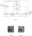
- FIG. 1C is a block diagram of an exemplary video decoding apparatus to which embodiments of the disclosure can be applied.
- the video decoding apparatus 101 includes an entropy decoding unit 150, a prediction unit 152, an inverse quantization unit 154, an inverse transform processing unit 156, a reconstruction unit 158 (which is represented by a circle with a plus sign subsequent to the inverse transform processing unit 155), a filter unit 159, and a decoded picture buffer 160.
- the video decoder 30 can include more, fewer, or different functional components.
- the inverse transform processing unit 155 can be eliminated in some cases.
- the entropy decoding unit 150 can perform entropy decoding on a received bitstream, and extract information such as a syntax element, a quantized coefficient block, and motion information of a PU.
- the prediction unit 152, the inverse quantization unit 154, the inverse transform processing unit 156, the reconstruction unit 158, and the filter unit 159 can perform their respective operations based on the syntax element extracted from the bitstream.
- the inverse quantization unit 154 can perform inverse quantization on a quantized TU-associated coefficient block.
- the inverse transform processing unit 156 can perform one or more inverse transforms on the inverse quantized coefficient block so as to generate a reconstructed residual block for a TU.
- the prediction unit 152 includes an inter prediction unit 162 and an intra prediction unit 164. If a PU is encoded through intra encoding, the intra prediction unit 164 can determine an intra prediction mode for the PU based on the syntax element parsed from the bitstream, perform intra prediction according to the determined intra prediction mode and reconstructed reference information neighbouring the PU obtained from the decoded picture buffer 160, and generate a prediction block for the PU. If the PU is encoded through inter encoding, the inter prediction unit 162 can determine one or more reference blocks for the PU according to motion information of the PU and a corresponding syntax element, and generate a prediction block for the PU based on the reference blocks obtained from decoded picture buffer 160.
- the reconstruction unit 158 can obtain a reconstructed picture based on a predicted block for a PU generated by the prediction unit 152 and a TU-associated reconstructed residual block.
- the filter unit 159 can perform in-loop filtering on the reconstructed picture, where the reconstructed picture subject to filtering is stored in the decoded picture buffer 160.
- the decoded picture buffer 160 can provide reference pictures for subsequent motion compensation, intra prediction, inter prediction, etc., or can output the reconstructed picture subject to filtering as decoded video data in order for presentation on a display apparatus.
- a picture is partitioned into blocks, a prediction block of a current block is generated through intra prediction or inter prediction of the current block or through other algorithms, the prediction block is subtracted from an original block of the current block to obtain a residual block, transform and quantization is performed on the residual block to obtain a quantization coefficient, and entropy coding is performed on the quantization coefficient to generate a bitstream.
- intra prediction or inter prediction is performed on a current block to generate a prediction block of the current block.
- inverse quantization and inverse transform is performed on a quantization coefficient obtained by parsing a bitstream, so as to obtain a residual block, and the prediction block is added to the residual block to obtain a reconstructed block, where the reconstructed block forms a reconstructed picture.
- a decoded picture is obtained by performing in-loop filtering on the reconstructed picture on a picture basis or on a block basis.
- a decoded picture is obtained through operations similar to those performed at the decoding end, and the decoded picture obtained at the encoding end is generally referred to as a reconstructed picture.
- the decoded picture can be used as a reference picture for inter prediction of a subsequent picture.
- Block partition information determined at the encoding end, as well as mode information or parameter information for prediction, transformation, quantization, entropy coding, in-loop filtering, etc., are carried in the bitstream when necessary.
- the block partition information, as well as the mode information or the parameter information for prediction, transformation, quantization, entropy coding, in-loop filtering, etc. that are the same as such information at the encoding end, so as to ensure that the decoded picture obtained at the encoding end is the same as the decoded picture obtained at the decoding end.
- an LIC method is provided.
- an illumination difference is refined by using an illumination compensation model, to obtain a prediction block after illumination compensation, which can eliminate impact caused by a flash lamp or an illumination change, thereby achieving better overall prediction effect.
- a correlation of change between prediction samples in a coding block and reference samples is fitted with aid of a correlation between neighbouring reconstructed samples of the current block and neighbouring reconstructed samples of a reference block. If top neighbouring reconstructed samples and left neighbouring reconstructed samples of a current block in a current picture can be obtained, top neighbouring reconstructed samples and left neighbouring reconstructed samples of a reference block in a reference picture can also be obtained.
- a corresponding fitting model can be obtained by modeling the neighbouring reconstructed samples of the current block and the neighbouring reconstructed samples of the reference block, and the fitting model is referred to as an LIC model, or can be referred to as a linear model or a "model" for short.
- neighboring refers to spatial neighbouring
- the reconstructed sample can also be referred to as a reference sample, a reconstructed reference sample, a template sample, a template reference sample, and the like.
- modeling for the LIC is model implemented through linear fitting. Illumination changes between the current block and the reference block are fitted by using a scaling parameter a and an offset parameter b, and a prediction value of a sample in the current block is updated by using a model parameter calculated.
- Pred(x, y) represents a prediction value before illumination compensation (i. e. a prediction value which is not subject to illumination compensation), for example, a sample value in a reference picture that is pointed to by an MV at ( x, y ).
- Pred' (x, y) represents a prediction value after illumination compensation.
- a represents a scaling parameter in the model
- b represents an offset parameter in the model.
- the update of the prediction value can be applied to both a luma component and a chroma component.
- the scale parameter a and the offset parameter b are calculated according to the neighbouring reconstructed samples of the current block and the neighbouring reconstructed samples of the reference block.
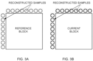
- the reconstructed samples illustrated in FIG. 3A include top neighbouring reconstructed samples and left neighbouring reconstructed samples of the reference block, where the reconstructed samples in the reference picture can be obtained by performing interpolation on reconstructed samples.
- the reconstructed samples illustrated in FIG. 3B include top neighbouring reconstructed samples and left neighbouring reconstructed samples of the current block, and the reconstructed samples in the current picture can be reconstructed samples in the current picture.
- the neighbouring reconstructed samples of the reference block and the neighbouring reconstructed samples of the current block are a single row or a single column, but the disclosure is not limited thereto.
- the scaling parameter a and the offset parameter b can be obtained.
- Curr_Rec neigh represents the neighbouring reconstructed sample of the current block
- Ref_Rec neigh represents the neighbouring reconstructed sample of the reference block
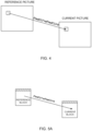
- the current block can be a current CU, or a current PU, etc. in the current picture.
- the reference block is a reconstructed CU or PU used for inter prediction of the current block in the reference picture, and the location of the reference block is determined according to the current block and an MV.
- the current block and the reference block have the same size.
- the number and positions of reconstructed samples for calculating the model parameter are determined according to the width and the height of the current block. In an example, if at least one of the width or the height of the current block is equal to 4, 4 top neighbouring reconstructed samples of the current block and 4 left neighbouring reconstructed samples of the current block are selected, so as to calculate the LIC model parameter. For example, if the width of the current block is 16 and the height of the current block is 4, all the 4 left neighbouring reconstructed samples of the current block are selected, and 4 out of 16 top neighbouring reconstructed samples of the current block are selected at a step size of 3, so as to calculate the LIC model parameter.
- the number of reconstructed samples selected from the top of the current block and the number of reconstructed samples selected from the left of the current block are determined based on the minimum between the width and the height of the current block.
- the scaling factor a and the offset parameter b are obtained by means of least square error.
- the reconstructed sample obtained from the reference picture i. e. the neighbouring reconstructed sample of the reference block
- the reconstructed sample obtained from the current picture i. e.
- a grid in a current picture represents a current block
- a grid in a reference picture represents a reference block of the current block
- PredCU represents a prediction block before LIC
- PredCU' represents a prediction block after LIC
- change of a prediction value after LIC is represented by formula (1).
- the LIC model parameter is calculated according to the top neighbouring reconstructed samples and the left neighbouring reconstructed samples of the current block and the top neighbouring reconstructed samples and the left neighbouring reconstructed samples of the reference block, which is referred to as an LIC_top-and-left (LIC_TL) mode, where T represents top, and L represents left.
- the LIC_TL mode can also be referred to as an original illumination compensation mode.
- the LIC model parameter is calculated according to the top neighbouring reconstructed samples and the left neighbouring reconstructed samples of the current block and the top neighbouring reconstructed samples and the left neighbouring reconstructed samples of the reference block. If both the top neighbouring reconstructed samples and the left neighbouring reconstructed samples of the current block are available, the top neighbouring reconstructed samples and the left neighbouring reconstructed samples of both the current block and the reference block (including the top neighbouring reconstructed samples and the left neighbouring reconstructed samples of the current block, and the top neighbouring reconstructed samples and the left neighbouring reconstructed samples of the reference block) are used to calculate the LIC model parameter.
- the LIC_TL mode it is not required that both the top neighbouring reconstructed samples and the left neighbouring reconstructed samples of the current block are available. If only the top neighbouring reconstructed samples of the current block are available, in the LIC_TL mode, only the top neighbouring reconstructed samples of both the current block and the reference block (including the top neighbouring reconstructed samples of the current block and the top neighbouring reconstructed samples of the reference block) are used to calculate the LIC model parameter.
- the left neighbouring reconstructed samples of the current block are available, in the LIC_TL mode, only the left neighbouring reconstructed samples of both the current block and the reference block (including the left neighbouring reconstructed samples of the current block and the left neighbouring reconstructed samples of the reference block) are used to calculate the LIC model parameter.
- the LIC method in the LIC_TL mode in this embodiment can be applied to common inter prediction (i. e. inter mode), a merge prediction mode (i. e. merge mode), and a sub-block mode.
- common inter prediction i. e. inter mode
- merge prediction mode i. e. merge mode
- sub-block mode i. e. sub-block mode
- the LIC method in the LIC_TL mode in this embodiment is applicable only to a single-frame prediction mode, but is not applicable to a multi-frame bi-directional reference mode.
- the illumination compensation method in this embodiment there is a relationship between the illumination compensation method in this embodiment and other inter prediction methods adopted.
- the illumination compensation method cannot be applied together with a bi-directional optical flow (BDOF) technology and a symmetric motion vector difference (SMVD) mode.
- BDOF bi-directional optical flow
- SMVD symmetric motion vector difference
- LIC_T LIC_top
- LIC_L LIC_left
- AMVP advanced motion vector prediction
- LIC_T mode only the top neighbouring reconstructed samples of the current block and the top neighbouring reconstructed samples of the reference block are used to calculate an LIC model parameter.
- LIC_TL mode also only the top neighbouring reconstructed samples of the current block and the top neighbouring reconstructed samples of the reference block are used to calculate the LIC model parameter, if only the top neighbouring reconstructed samples of the current block are available.
- the LIC_L mode only the left neighbouring reconstructed samples of the current block and the left neighbouring reconstructed samples of the reference block are used to calculate the LIC model parameter.
- the LIC_TL mode also only the left neighbouring reconstructed samples of the current block and the left neighbouring reconstructed samples of the reference block are used to calculate the LIC model parameter, if only the left neighbouring reconstructed samples of the current block are available.
- LIC For example, if LIC is applied to a current block located at the top boundary of a picture, only the left neighbouring reconstructed samples are available.
- the LIC_TL mode when performing trial encoding by applying the LIC_TL mode, according to availability of the reconstructed samples, only the left neighbouring reconstructed samples of the current block and the left neighbouring reconstructed samples of the reference block are used to calculate the LIC model parameter.
- the LIC_TL mode is the same as the LIC_L mode, which results in repeated calculations.
- the number of the reconstructed samples selected when the current block is at the boundary is the same as the number of reconstructed samples selected when the current block is not at the boundary, and the number of reconstructed samples selected is determined according to the minimum value between the width and the height. If the current block is at the top boundary of the picture and LIC is applied to the current block, and the size of the current block is 4 ⁇ 32, 4 out of 32 left neighbouring reconstructed samples of the current block will be selected at a step size of 8. Such kind of selection will result in large step size, which is in turn likely to result in a large offset and inaccuracy in calculation of the model parameter, and as a result, encoding performance will be degraded.
- An embodiment of the disclosure provides an LIC method.
- the method is applied to an encoding end. As illustrated in FIG. 6 , the method includes the following.
- Step 110 if LIC is enabled for inter prediction of a current block, an LIC mode applied during trial encoding of the current block is determined according to availability of neighbouring reconstructed samples of the current block.
- prediction modes can be traversed. If a first inter mode is applied to the current block, an LIC-related syntax element is obtained, so as to determine whether LIC is enabled for inter prediction of the current block. If LIC is enabled, trial encoding needs to be performed, so as to determine, according to a rate-distortion cost, whether to apply LIC.
- Step 120 trial encoding is performed on the current block by applying the determined LIC mode, and a rate-distortion cost is calculated. Whether to apply LIC when performing inter prediction on the current block is determined according to the rate-distortion cost.
- the LIC mode with the minimum rate-distortion cost is an optimal LIC mode.
- other inter prediction technologies also referred to as inter prediction modes
- rate-distortion costs corresponding to these modes are calculated and compared with the rate-distortion cost of the optimal LIC mode. If the rate-distortion cost value of the optimal LIC mode is the smallest, it is determined that LIC is applied when performing inter prediction on the current block; otherwise, LIC is not applied when performing inter prediction on the current block.
- the "optimal LIC mode” is not limited to a single LIC mode, and can also refer to a combination of an LIC mode and another inter mode(s) that can be applied together with the LIC mode.
- LIC if LIC is enabled for inter prediction of the current block, boundary detection on the current block is introduced to determine availability of the neighbouring reconstructed samples of the current block, and the LIC mode applied during trial encoding of the current block is determined according to availability of the neighbouring reconstructed samples of the current block. If only top neighbouring reconstructed samples or only left neighbouring reconstructed samples of the current block are available, only one or two modes among an LIC_TL mode, an LIC_T mode, and an LIC_L mode are applied when performing trial encoding, instead of performing trial encoding by applying all the three LIC modes one by one, thereby eliminating data redundancy and reducing bits to be transmitted, and thus reducing overhead.
- the LIC mode applied during trial encoding of the current block is determined according to availability of the neighbouring reconstructed samples of the current block as follows. If both the top neighbouring reconstructed samples and the left neighbouring reconstructed samples of the current block are available, trial encoding is performed by applying the LIC_TL mode, the LIC_T mode, and the LIC_L mode.
- trial encoding with one of the LIC modes is skipped, that is, the LIC_T mode or the LIC_L mode is not applied during trial encoding.
- the LIC mode applied during trial encoding of the current block is determined according to availability of the neighbouring reconstructed samples of the current block as follows. If only the top neighbouring reconstructed samples of the current block are available, trial encoding is performed by applying the LIC_TL mode and the LIC_L mode. If only the left neighbouring reconstructed samples of the current block are available, trial encoding is performed by applying the LIC_TL mode and the LIC_T mode. In the LIC_T mode, only the top neighbouring reconstructed samples of the current block and top neighbouring reconstructed samples of a reference block are used to calculate an LIC model parameter.
- the left neighbouring reconstructed samples of the current block can be obtained through filling to calculate the LIC model parameter.
- a value of a reconstructed sample which is closest to the left of the current block among the top neighbouring reconstructed samples of the current block can be assigned to all the left neighbouring reconstructed samples of the current block, or a specified value (for example, an intermediate value in a value range of samples) can be assigned to all the left neighbouring reconstructed samples of the current block.
- the top neighbouring reconstructed samples of the current block can be obtained through filling to calculate the LIC model parameter.
- the manner for filling is similar to the above, and is not described again herein.
- the method further includes the following.
- An LIC usage flag (a CU-level flag) of the current block is set to be true and signalled into a bitstream. If an LIC mode with the minimum rate-distortion cost during trial encoding is the LIC_TL mode, an extended LIC flag of the current block is set to be false and signalled into the bitstream. If the LIC mode with the minimum rate-distortion cost during trial encoding is the LIC_T mode or the LIC_L mode, the extended LIC flag of the current block is set to be true and signalled into the bitstream.
- the LIC mode with the minimum rate-distortion cost can be determined according to availability of the neighbouring reconstructed samples of the current block. Specifically, if only the top neighbouring reconstructed samples of the current block are available, the optimal LIC mode is determined to be the LIC_T mode; if only the left neighbouring reconstructed samples of the current block are available, the optimal LIC mode is determined to be the LIC_L mode.
- trial encoding in the two LIC modes is skipped, that is, the LIC_T mode and the LIC_L mode are not applied during trial encoding.
- the LIC mode applied during trial encoding of the current block is determined according to availability of the neighbouring reconstructed samples of the current block as follows. If only the top neighbouring reconstructed samples or only the left neighbouring reconstructed samples of the current block are available, determine to apply the LIC_TL mode when performing trial encoding on the current block.
- the method further includes the following.
- An LIC usage flag of the current block is set to be true and signalled into a bitstream. If only the top neighbouring reconstructed samples or only the left neighbouring reconstructed samples of the current block are available, a mode index of the LIC mode and an extended LIC flag of the current block do not need to be encoded.
- the extended LIC flag of the current block is set to be false and signalled into the bitstream; if the LIC mode with the minimum rate-distortion cost is the LIC_T mode or the LIC_L mode, the extended LIC flag of the current block is set to be true and signalled into the bitstream, and a mode index of the LIC mode with the minimum rate-distortion cost is encoded and signalled into the bitstream.
- encoding of the LIC-related syntax element of the current block can also be changed, for example, encoding of the mode index of the LIC mode is skipped, or encoding of the mode index and the extended LIC flag is skipped, which can save encoding time and reduce overhead, thereby improving encoding efficiency.
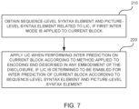
- An embodiment of the disclosure further provides a video encoding method. As illustrated in FIG. 7 , the method includes the following.
- Step 210 if a first inter mode is applied to a current block, a sequence-level syntax element and a picture-level syntax element related to LIC are obtained.
- prediction modes can be traversed. If the first inter mode is applied to the current block, a sequence-level LIC enable flag and a picture-level LIC usage flag are obtained.
- the sequence-level LIC enable flag indicates whether LIC is enabled for a current encoder, and the picture-level LIC usage flag indicates whether LIC is enabled for a current picture.
- Step 220 if LIC is determined to be enabled for inter prediction of the current block according to the sequence-level syntax element and the picture-level syntax element, LIC is applied when performing inter prediction on the current block according to the LIC method applied to the encoding end described in any embodiment of the disclosure.
- the sequence-level LIC enable flag is true (indicates that LIC is enabled) and the picture-level LIC usage flag is true (indicates that LIC is applied), then it can be determined that LIC is enabled for inter prediction of the current block. If at least one of the two flags is false, it is determined that LIC is disabled for inter prediction of the current block.
- a picture-level bit indicating to enable LIC is referred to as an LIC usage flag
- a CU-level flag indicating to enable LIC is referred to as an LIC usage flag in order for differentiation between the two.
- the LIC method applied to the encoding end in any embodiment of the disclosure is adopted to perform boundary detection on the current block, so as to determine availability of the neighbouring reconstructed samples of the current block. If only neighbouring reconstructed samples at one side of the current block are available, trial encoding in at least one of an LIC_T mode or an LIC_L mode is skipped, and encoding of some LIC-related syntax elements (such as flag and index) is omitted, which can save encoding time and reduce bit overhead, thereby improving encoding efficiency.
- some LIC-related syntax elements such as flag and index
- a prediction-mode flag needs to be parsed as a common inter prediction mode, which does not include a merge mode.
- application of the LIC_T mode and the LIC_L mode is extended to the merge mode, and a syntax element is introduced into the merge mode to indicate the LIC_T mode or the LIC_L mode.
- the LIC method in any embodiment of the disclosure is applied to a merge mode in a uni-directional reference mode, but is not applied together with a combined inter-intra prediction (CIIP) mode, a geometric partitioning mode (GPM), or an affine mode (Affine_merge) in the merge mode in the uni-directional reference mode, and can be applied together with a merge mode with motion vector difference (MMVD_Merge).
- CIIP inter-intra prediction
- GPSM geometric partitioning mode
- Ad_merge affine mode
- MMVD_Merge merge mode with motion vector difference
- the LIC method in any embodiment of the disclosure is applied to a merge mode in a bi-directional reference mode (in the bi-directional reference mode, LIC can be applied only to the merge mode), but is not applied together with a BDOF mode, a decoder-side motion vector derivation mode, or a bi-prediction with CU-level weights (BCW) mode in the merge mode in the bi-directional reference mode, and can be applied together with a regular merge mode (regular_Merge).
- a regular merge mode regular merge mode
- a mode index of the LIC mode and an LIC-related flag (such as an LIC usage flag) of the current block inherit those of a neighbouring block or a corresponding prediction block (the neighbouring block for inter prediction is a spatial neighbouring block, and the prediction block is obtained from a reference picture and is a temporal block).
- the LIC usage flag of the current block inherits those of the neighbouring block or the corresponding prediction block.
- only the LIC usage flag is inherited while the mode index of the LIC mode is not inherited, and a mode index of the LIC_TL mode is used as a default mode index.
- RDO rate-distortion optimization
- An embodiment of the disclosure further provides an LIC method.
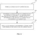
- the method is applied to a decoding end. As illustrated in FIG. 8 , the method includes the following.
- Step 310 an LIC usage flag of a current block is parsed.
- a sequence-level LIC enable flag and a picture-level LIC usage flag are obtained. If the LIC enable flag is true (indicating that LIC is enabled for a current decoder) and the LIC usage flag is true (indicating that LIC is applied), the LIC usage flag of the current block is parsed to determine whether LIC is applied to the current block.
- Step 320 if LIC is determined to be applied to the current block according to the LIC usage flag, an LIC mode applied to the current block is determined according to availability of neighbouring reconstructed samples of the current block.
- an LIC-related syntax element is parsed according to availability of the neighbouring reconstructed samples of the current block, so as to determine the LIC mode applied to the current block.
- Step 330 LIC is applied according to the determined LIC mode, when performing inter prediction on the current block.
- the neighbouring reconstructed samples of the current block and neighbouring reconstructed samples of a reference block can be selected according to the determined LIC mode to calculate an LIC model parameter; and according to the LIC model parameter, linear transformation is performed on a prediction block obtained after motion compensation on the current block, so as to obtain a prediction block after LIC; and a reconstructed block is obtained by adding the prediction block after LIC and a decoded residual.
- boundary detection is performed on the current block, and the LIC-related syntax element is parsed according to availability of the neighbouring reconstructed samples of the current block. If only neighbouring reconstructed samples at one side of the current block are available, the LIC mode applied to the current block can be determined through fewer syntax elements and a simpler parsing process, thereby saving bit overhead and improving encoding efficiency.
- the parsing process and semantics in this embodiment change accordingly.
- the LIC mode applied to the current block is determined according to availability of the neighbouring reconstructed samples of the current block as follows. An extended LIC flag of the current block is parsed. If the extended LIC flag is true and only top neighbouring reconstructed samples of the current block are available, determine that the LIC_L mode is applied to the current block. If the extended LIC flag is true and only left neighbouring reconstructed samples of the current block are available, determine that the LIC_T mode is applied to the current block.
- the LIC mode applied depends on the side of the current block at which the neighbouring reconstructed samples are available. Therefore, the LIC mode applied to the current block can be determined without using the mode index.
- the LIC mode applied to the current block is determined according to availability of the neighbouring reconstructed samples of the current block as follows. If the extended LIC flag is false, determine that an LIC_TL mode is applied to the current block. If the extended LIC flag is true and both the top neighbouring reconstructed samples and the left neighbouring reconstructed samples of the current block are available, an LIC mode index of the current block is parsed, and which one of the LIC_T mode or the LIC_L mode is applied to the current block is determined according to the LIC mode index.
- the parsing process and semantics in this embodiment change accordingly.
- the LIC mode applied to the current block is determined according to availability of the neighbouring reconstructed samples of the current block as follows. If both the top neighbouring reconstructed samples and the left neighbouring reconstructed samples of the current block are available, the extended LIC flag of the current block is parsed. If the extended LIC flag is false, determine that the LIC_TL mode is applied to the current block. If the extended LIC flag is true, the LIC mode index of the current block is parsed, and determine, according to the LIC mode index, whether the LIC_T mode or the LIC_L mode is applied to the current block.
- the LIC mode applied the current block is determined according to availability of the neighbouring reconstructed samples of the current block as follows. If the top neighbouring reconstructed samples or the left neighbouring reconstructed samples of the current block are unavailable, the extended LIC flag does not need to be parsed and is false by default, and determine that the LIC_TL mode is applied to the current block. At the encoding end, the LIC_T mode and the LIC_L mode are disabled if only neighbouring reconstructed samples at one side of the current block are available.
- LIC is applied according to the determined LIC mode as follows. If the LIC_T mode is applied to the current block, an LIC model parameter is calculated by using only the top neighbouring reconstructed samples of the current block and top neighbouring reconstructed samples of a reference block, and linear transformation is performed on a prediction block of the current block according to the LIC model parameter to obtain a prediction block after LIC. If the LIC_L mode is applied to the current block, the LIC model parameter is calculated by using only the left neighbouring reconstructed samples of the current block and left neighbouring reconstructed samples of the reference block, and linear transformation is performed on the prediction block of the current block according to the LIC model parameter to obtain the prediction block after LIC.
- the LIC model parameter is calculated according to the top neighbouring reconstructed samples and the left neighbouring reconstructed samples of the current block and the top neighbouring reconstructed samples and the left neighbouring reconstructed samples of the reference block, and linear transformation is performed on the prediction block of the current block according to the LIC model parameter to obtain the prediction block after LIC.
- Embodiments of the disclosure further provide a video decoding method. As illustrated in FIG. 9 , the method includes the following.
- Step 410 if a first inter mode is determined to be applied to a current block, a sequence-level syntax element and a picture-level syntax element related to usage of LIC are obtained.
- the parsed sequence-level and picture-level syntax elements can include a sequence-level LIC enable flag and a picture-level LIC usage flag.
- Step 420 if LIC is determined to be enabled for inter prediction of the current block according to the sequence-level syntax element and the picture-level syntax element, LIC is applied when performing inter prediction on the current block according to the LIC method applied to the decoding end in any embodiment of the disclosure.
- an LIC usage flag of the current block can be parsed according to the LIC method applied to the decoding end in any embodiment of the disclosure. If it is determined, according to the LIC usage flag, that LIC is applied to the current block, an LIC mode applied to the current block is determined according to availability of neighbouring reconstructed samples of the current block, and LIC is applied according to the determined LIC mode when performing inter prediction on the current block. In embodiments, during decoding, boundary detection is performed on the current block, and an LIC-related syntax element is parsed according to availability of the neighbouring reconstructed samples of the current block, which can save bit overhead and improve encoding efficiency.
- the LIC method in any embodiment of the disclosure is applied to a merge mode in a bi-directional reference mode (in the bi-directional reference mode, LIC can be applied only to the merge mode), but is not applied together with a BDOF mode, a decoder-side motion vector derivation mode, or a BCW mode in the merge mode in the bi-directional reference mode, and can be applied together with a regular merge mode (regular_Merge).
- a regular merge mode regular merge mode
- a mode index of the LIC mode and an LIC-related flag (such as an LIC usage flag) of the current block inherit those of a neighbouring block or a corresponding prediction block.
- the LIC usage flag of the current block inherits those of the neighbouring block or the corresponding prediction block.
- only the LIC usage flag is inherited while the mode index of the LIC mode is not inherited, and a mode index of the LIC_TL mode is used as a default mode index.
- a method for calculating the number of reconstructed samples selected is optimized, and the number of reconstructed samples selected is determined based on boundary detection on the current block.
- SampleNum represents the base number of the number of reconstructed samples selected
- cuWidth and cuHeight represent the width and the height of the current block respectively
- cuAbove means that the top neighbouring reconstructed samples of the current block are available
- cuLeft means that the left neighbouring reconstructed samples of the current block are available.
- the number of reconstructed samples selected is calculated according to the minimum value between the width and the height of the current block.
- boundary detection is introduced. If a condition that both the top neighbouring reconstructed samples and the left neighbouring reconstructed samples of the current block are available is satisfied, the number of reconstructed samples selected is calculated according to the minimum value between the width and the height of the current block. If the condition is not satisfied, whether the top neighbouring reconstructed samples of the current block are available is determined. If the top neighbouring reconstructed samples of the current block are available, the number of reconstructed samples selected is calculated according to the width of the current block. If the top neighbouring reconstructed samples of the current block are unavailable, the number of reconstructed samples selected is calculated according to the height of the current block.
- the optimized algorithm in embodiments can be combined with the LIC method in any embodiment of the disclosure, or can be applied to other LIC methods, for example, an LIC method in which only the LIC_TL mode is applied, and the like.
- trial encoding is performed on the current block by applying the determined LIC mode as follows.
- the number of reconstructed samples selected for calculating the LIC model parameter is determined according to the width of the current block; if only the left neighbouring reconstructed samples of the current block are available, the number of reconstructed samples selected for calculating the LIC model parameter is determined according to the height of the current block.
- the LIC model parameter is calculated according to the top neighbouring reconstructed samples and the left neighbouring reconstructed samples of the current block and the top neighbouring reconstructed samples and the left neighbouring reconstructed samples of the reference block as follows. If only the top neighbouring reconstructed samples of the current block are available, the number of reconstructed samples selected for calculating the LIC model parameter is determined according to the width of the current block. If only the left neighbouring reconstructed samples of the current block are available, the number of reconstructed samples selected for calculating the LIC model parameter is determined according to the height of the current block.
- the number of reconstructed samples selected for calculating an LIC model parameter is optimized, which can prevent a step size for reconstructed sample selection from being too large, thereby improving accuracy of model parameter calculation and improving encoding performance.
- An embodiment of the disclosure provides a video encoding method and a video decoding method.
- CU-level boundary detection for the illumination compensation mode is introduced at both the encoding end and the decoding end.
- the encoding end if the current block is at the top boundary, trial encoding in the LIC_L mode is skipped; and if the current block is at the left boundary, trial encoding in the LIC_T mode is skipped.
- the decoding end when parsing the syntax element of the current block, determine whether the current block is at the boundary. If the current block is at the boundary, the last syntax element (mode index) does not need to be parsed; otherwise, all the LIC-related syntax elements of the current block need to be parsed.
- a current CU is taken as an example of the current block.
- the video encoding method in this embodiment includes the following.
- Step one an encoder traverses prediction modes. If an inter mode that can apply LIC is applied to a current CU, an LIC enable flag and a picture-level LIC usage flag are obtained.
- the LIC enable flag is a sequence-level flag, and indicates that LIC is enabled for the current encoder. If the LIC enable flag is true and the picture-level LIC usage flag is true, at the encoding end, the LIC prediction method is tried, and proceed to step two. If the LIC enable flag or the LIC usage flag is false, at the encoding end, the LIC prediction method will not be tried, and proceed to step three directly without performing step two.
- Step two the encoder obtains information of neighbouring reconstructed samples of the current CU. If both top neighbouring reconstructed samples and left neighbouring reconstructed reference samples of the current CU are available, a first round, a second round, and a third round of trial encoding are performed. If only the left neighbouring reconstructed samples of the current CU are available, the first round and the second round of trial encoding are performed. If only the top neighbouring reconstructed samples of the current CU are available, the first round and the third round of trial encoding are performed.
- reconstructed samples for calculating the LIC model parameter are selected by applying the LIC_TL mode.
- the process includes the following.
- the top neighbouring reconstructed samples and the left neighbouring reconstructed samples of the current CU are selected, where the number of reconstructed samples selected is determined based on the minimum value among the width and the height of the current CU.
- top neighbouring reconstructed samples and left neighbouring reconstructed samples of a corresponding CU (i. e. reference CU) in a reference picture are selected. If the current CU is not at the boundary, both the top neighbouring reconstructed samples and the left neighbouring reconstructed samples of the current CU and those of the reference CU can be selected. If the current CU is at the boundary, only the top neighbouring reconstructed samples or only the left neighbouring reconstructed samples of the current CU and those of the reference CU can be selected.
- the reconstructed samples obtained are modeled through the linear model calculation method described above, to calculate a scaling factor a and an offset parameter b. Then, linear transformation is performed on a motion-compensated prediction block by using the scaling factor a and the offset parameter b, to obtain a prediction block after LIC of the current CU. A difference between the prediction block and original samples corresponding to the current CU is calculated to obtain a residual of the current CU.
- a rate-distortion cost value is calculated through operations such as transform and quantization, and is denoted as cost1.
- reconstructed samples for calculating the LIC model parameter are selected by applying the LIC_T mode.
- the process includes the following. At the encoding end, only the top neighbouring reconstructed samples of the current CU are selected, and only the top neighbouring reconstructed samples of the corresponding CU in the reference picture are selected. The processing after the reconstructed samples are selected is the same as that in the first round, and a rate-distortion cost value is calculated and denoted as cost2.
- reconstructed samples for calculating the LIC model parameter are selected by applying the LIC_L mode.
- the process includes the following. At the encoding end, only the left neighbouring reconstructed samples of the current CU are selected, and only the left neighbouring reconstructed samples of the corresponding CU in the reference picture are selected. The processing after the reconstructed samples are selected is the same as that in the first round, and a rate-distortion cost value is calculated and denoted as cost3.
- cost1, cost2, and cost 3 are compared, and the minimum rate-distortion cost value is denoted as costLic.
- information of a current LIC mode is stored, which includes a mode index of the LIC mode.
- a mode index of the LIC_TL mode corresponding to cost1 is 0, a mode index of the LIC_T mode corresponding to cost2 is 1, and a mode index of the LIC_L mode corresponding to cost3 is 2.
- Step three at the encoding end, other inter prediction modes are traversed, rate-distortion cost values corresponding to these prediction modes are calculated, and a prediction mode corresponding to the minimum rate-distortion cost value is determined as the optimal prediction mode for the current CU, which includes several cases.
- LIC is enabled for the current CU and costLic is the minimum value compared with the rate-distortion cost values of other prediction modes, it is determined that the LIC is applied to the current CU, and a CU-level LIC usage flag of the current CU is set to be true and signalled into a bitstream.
- a mode index of an LIC mode corresponding to costLic is greater than 0 (the mode index of the LIC_T mode and the mode index of the LIC_L mode are greater than 0)
- an extended LIC flag is set to be true and signalled into the bitstream, and the mode index is encoded (for example, by means of equiprobable encoding, etc.) and signalled into the bitstream; if the mode index of the LIC mode corresponding to costLic is equal to 0 (the mode index of the LIC_TL mode is equal to 0), the extended LIC flag is set to be false and signalled into the bitstream.
- the extended LIC flag is set to be true and signalled into the bitstream; if the mode index of the LIC mode corresponding to costLic is equal to 0, the extended LIC flag is set to be false and signalled into the bitstream.
- the mode index does not need to be encoded in this case.
- LIC is not applied to the current CU, and the CU-level LIC usage flag the current CU is set to be false and signalled into the bitstream.
- costLic may correspond to the LIC_T mode having the mode index of 1, or may correspond to the LIC_L mode having the mode index of 2.
- 1 can be subtracted from the mode index. In this way, if the mode index is 1, the encoded mode index is 0; and if the mode index is 2, the encoded mode index is 1.
- the LIC_T mode is determined to be applied; and if the encoded mode index is parsed as 1, the LIC_L mode is determined to be applied.
- Step four after traversing all the CUs, the encoder outputs the bitstream after operations such as entropy coding.
- the LIC_TL mode can also be referred to as a top-and-left LIC mode
- the LIC_T mode can also be referred to as a top-only LIC mode
- the LIC_T mode can also be referred to as a left-only LIC mode.
- the video decoding method in this embodiment includes the following.
- Step one at the decoding end, a CU-level type flag is parsed. If the CU-level type flag indicates an inter mode, an LIC enable flag is obtained, where the LIC enable flag is a sequence-level flag, and indicates that LIC is enabled for a current decoder. If the LIC enable flag is true, a picture-level LIC usage flag needs to be parsed when decoding each picture.
- an LIC usage flag (CU-level flag) of a current CU is parsed.
- a mode index lic_idx (encoded mode index) of an LIC mode is parsed. If lic_idx is 1, the LIC_L mode is determined to be applied to the current CU. If lic_idx is 0, the LIC_T mode is determined to be applied to the current CU.
- the mode index does not need to be parsed. If only the top neighbouring reconstructed samples of the current CU are available, it is determined that the LIC_T mode is applied to the current CU. If only the left neighbouring reconstructed samples of the current CU are available, it is determined that the LIC_L mode is applied to the current CU.
- the LIC usage flag of the current CU does not need to be parsed, and the CU-level LIC usage flag is false by default, and then proceed to step three.
- Step two at the decoding end, an LIC mode applied is determined according to the index obtained by parsing in the previous step, and neighbouring reconstructed samples of the current CU are selected according to the determined LIC mode, where the number of reconstructed samples selected depends on the width or height of the current CU.
- neighbouring reconstructed samples of a corresponding CU in a reference picture are selected.
- the reconstructed samples selected are modeled through a linear model calculation method to calculate a scaling factor a and an offset parameter b, and linear transformation is performed on a motion-compensated prediction block, that is, scaled a times and compensated by b , so as to obtain a prediction block after LIC of the current CU.
- Step three information such as usage flag or index of other inter prediction modes is parsed, and a final prediction block of the current CU is obtained according to the information parsed.
- Step four a bitstream is parsed to obtain residual information, time-domain residual information (also referred to as a decoded residual or a reconstructed residual) is obtained through inverse quantization and inverse transform, and the final prediction block and the time-domain residual information are added to obtain a reconstructed sample block, i. e. a reconstructed block, of the current block.
- time-domain residual information also referred to as a decoded residual or a reconstructed residual
- the final prediction block and the time-domain residual information are added to obtain a reconstructed sample block, i. e. a reconstructed block, of the current block.
- Step five a reconstructed picture is obtained after all the reconstructed sample blocks are subject to technologies such as in-loop filtering.
- the reconstructed picture can be output as a video or can be used as a reference for decoding a subsequent picture.
- the disclosure is not limited thereto.
- limitation can be set for application of LIC at a CU-level. If the product of the width and the height of the current CU is less than 32, LIC is disabled.
- sps_lic_enable_flag is the sequence-level LIC enable flag
- ph_lic_enable_flag is the picture-level LIC usage flag
- lic_flag is an LIC usage flag of the current CU
- lic_ext is the extended LIC flag of the current CU
- lic_index is an encoded mode index of the current CU. According to lic_ext + lic_index, a mode index of the LIC mode applied to the current CU before encoding can be obtained.
- JVET has established a group for research on a coding model beyond H.266NVC, and the model, i. e., platform test software, is named enhanced compression model (ECM).
- ECM enhanced compression model
- newer and more efficient compression algorithms are introduced on the basis of version 10.0 of VVC test model (VTM10.0), and lots of intra prediction technologies and inter prediction technologies are applied.
- VTM10.0 VVC test model
- RA random access
- this embodiment has improvement in chroma component.
- encoding time is effectively reduced by skipping trial encoding when at the boundary, and the encoding time is reduced by 2% ⁇ 3% on average.
- redundant information in the bitstream is eliminated.
- Another embodiment of the disclosure provides a video encoding method and a video decoding method.
- CU-level boundary detection for the illumination compensation mode is introduced at both the encoding end and the decoding end.
- the encoding end if the current block is at any boundary, only the original illumination compensation mode, that is, the LIC_TL mode, is enabled, while trial encoding in the LIC_L mode and the LIC_T mode is disabled.
- the decoding end when parsing an LIC-related syntax element of the current block, whether the current block is at the boundary is determined. If the current block is at any boundary, only a 1 st syntax element, i. e. the LIC usage flag, needs to be parsed.
- the LIC_TL mode can be determined to be applied; and if the LIC usage flag is false, it indicates that LIC is not applied when performing inter prediction on the current block.
- a current CU is taken as an example of the current block.
- the video encoding method in this embodiment includes the following.
- Step one an encoder traverses prediction modes. If an inter mode that can apply LIC is applied to a current CU, an LIC enable flag and a picture-level LIC usage flag are obtained.
- the LIC enable flag is a sequence-level flag, and indicates that LIC is enabled for the current encoder. If the sequence-level LIC enable flag is true and the picture-level LIC usage flag is true, at the encoding end, the LIC prediction method is tried, and proceed to step two. If at least one of the sequence-level LIC enable flag or the picture-level LIC usage flag is false, at the encoding end, the LIC prediction method will not be tried, and proceed to step three directly without performing step two.
- Step two the encoder obtains information of neighbouring reconstructed samples of the current CU. If both top neighbouring reconstructed samples and left neighbouring reconstructed reference samples of the current CU are available, a first round, a second round, and a third round of trial encoding are performed. If only the left neighbouring reconstructed samples or only the top neighbouring reconstructed samples of the current CU are available, only the first round of the trial encoding is performed.
- reconstructed samples for calculating the LIC model parameter are selected by applying the LIC_TL mode.
- the process thereof includes the following.
- the top neighbouring reconstructed samples and the left neighbouring reconstructed samples of the current CU are selected, where the number of reconstructed samples selected is determined based on the minimum value among the width and the height of the current CU.
- top neighbouring reconstructed samples and left neighbouring reconstructed samples of a corresponding CU (i. e. reference CU) in a reference picture are selected. If the current CU is not at the boundary, both the top neighbouring reconstructed samples and the left neighbouring reconstructed samples of the current CU and those of the reference CU can be selected. If the current CU is at the boundary, only the top neighbouring reconstructed samples or only the left neighbouring reconstructed samples of the current CU and those of the reference CU can be selected.
- the reconstructed samples obtained are modeled through the linear model calculation method described above, to calculate a scaling factor a and an offset parameter b. Then, linear transformation is performed on a motion-compensated prediction block by using the scaling factor a and the offset parameter b, to obtain a prediction block after LIC of the current CU. A difference between the prediction block and original samples corresponding to the current CU is calculated to obtain a residual of the current CU.
- a rate-distortion cost value is calculated through operations such as transform and quantization, and is denoted as cost1.
- reconstructed samples for calculating the LIC model parameter are selected by applying the LIC_T mode.
- the process includes the following. At the encoding end, only the top neighbouring reconstructed samples of the current CU are selected, and only the top neighbouring reconstructed samples of the corresponding CU in the reference picture are selected. The processing after the reconstructed samples are selected is the same as that in the first round, and a rate-distortion cost value is calculated and denoted as cost2.
- reconstructed samples for calculating the LIC model parameter are selected by applying the LIC_L mode.
- the process includes the following. At the encoding end, only the left neighbouring reconstructed samples of the current CU are selected, and only the left neighbouring reconstructed samples of the corresponding CU in the reference picture are selected. The processing after the reconstructed samples are selected is the same as that in the first round, and a rate-distortion cost value is calculated and denoted as cost3.
- cost1, cost2, and cost 3 are compared, and the minimum rate-distortion cost value is denoted as costLic.
- information of a current LIC mode is stored, which includes a mode index of the LIC mode.
- a mode index of the LIC_TL mode corresponding to cost1 is 0, a mode index of the LIC_T mode corresponding to cost2 is 1, and a mode index of the LIC_L mode corresponding to cost3 is 2.
- Step three at the encoding end, other inter prediction modes are traversed, rate-distortion cost values corresponding to these prediction modes are calculated, and a prediction mode corresponding to the minimum rate-distortion cost value is determined as the optimal prediction mode for the current CU, which includes several cases.
- LIC is enabled for the current CU and costLic is the minimum value compared with the rate-distortion cost values of other prediction modes, it is determined that the LIC is applied to the current CU, and a CU-level LIC usage flag of the current CU is set to be true and signalled into a bitstream.
- an extended LIC flag is set to be true and signalled into the bitstream, and the mode index is encoded (for example, by means of equiprobable encoding, etc.) and signalled into the bitstream; if the mode index of the LIC mode corresponding to costLic is equal to 0, the extended LIC flag is set to be false and signalled into the bitstream.
- the LIC_TL mode is applied by default, and other syntax elements do not need to be signalled into the bitstream.
- LIC is not applied to the current CU, and the CU-level LIC usage flag the current CU is set to be false and signalled into the bitstream.
- Step four after traversing all the CUs, the encoder outputs the bitstream after implementing technologies such as entropy coding.
- the video decoding method in this embodiment includes the following.
- Step one at the decoding end, a CU-level type flag is parsed. If the CU-level type flag indicates an inter mode, an LIC enable flag is obtained, where the LIC enable flag is a sequence-level flag, and indicates that LIC is enabled for a current decoder. If the LIC enable flag is true, a picture-level LIC usage flag needs to be parsed when decoding each picture.
- a mode index lic_idx (encoded mode index) of an LIC mode is parsed. If lic_idx is 1, the LIC_L mode is determined to be applied to the current CU. If lic_idx is 0, the LIC_T mode is determined to be applied to the current CU.
- step three If at least one of the sequence-level LIC enable flag or the picture-level LIC usage flag is false, in the current decoding process, the CU-level LIC usage flag does not need to be parsed, and the CU-level LIC usage flag is false by default, and then step three is performed.
- Step two the decoder determines, according to the index obtained by parsing in the previous step, an LIC mode applied; and selects neighbouring reconstructed reference samples of the current CU according to the determined LIC mode, where the number of reconstructed samples selected depends on the width or height of the current CU.
- neighbouring reconstructed samples of a corresponding CU in a reference picture are selected.
- the reconstructed samples selected are modeled through a linear model calculation method to calculate a scaling factor a and an offset parameter b, and linear transformation is performed on a motion-compensated prediction block, that is, scaled a times and compensated by b , so as to obtain a prediction block after LIC of the current CU.
- Step three information such as usage flag or index of other inter prediction modes is parsed, and a final prediction block of the current CU is obtained according to the information parsed.
- Step four a bitstream is parsed to obtain residual information, time-domain residual information is obtained through inverse quantization and inverse transform, and the final prediction block and the time-domain residual information are added to obtain a reconstructed sample block of the current CU.
- Step five a reconstructed picture is obtained after all the reconstructed sample blocks are subject to technologies such as in-loop filtering.
- the reconstructed picture can be output as a video or can be used as a reference for subsequent decoding.
- limitation can be set for application of LIC at a CU-level. If the product of the width and the height of the current CU is less than 32, LIC is disabled.
- sps_lic_enable_flag is the sequence-level LIC enable flag
- ph_lic_enable_flag is the picture-level LIC usage flag
- lic_flag is the LIC usage flag of the current CU
- lic_ext is the extended LIC flag of the current CU
- lic_index is an encoded mode index of the current CU. According to lic_ext + lic_index, a mode index of the LIC mode applied to the current CU before encoding can be obtained.
- An embodiment of the disclosure further provides a video decoding apparatus.
- the video decoding apparatus includes a processor and a memory configured to store computer programs. When executing the computer programs, the processor can implement the video decoding method according to any embodiment of the disclosure.
- An embodiment of the disclosure further provides a video encoding apparatus.
- the video encoding apparatus includes a processor and a memory configured to store computer programs.
- the processor can implement the video encoding method according to any embodiment of the disclosure.
- the processor in embodiments of the disclosure can be a general-purpose processor, including a central processing unit ("CPU” for short), a network processor ("NP” for short), a microprocessor, or the like, and can also be other conventional processors or the like.
- the processor can also be a digital signal processor (DSP), an application-specific integrated circuit (ASIC), a field programmable gate array (FPGA), discrete logic or other programmable logic devices, discrete gates or transistor logic devices, discrete hardware components, or can be a combination of the above devices. That is, the processor in the foregoing embodiments can be any processing component or combination of components for implementing the methods, steps, and logical blocks disclosed in embodiments of the disclosure. If embodiments of the disclosure are implemented partially in software, the instructions for the software can be stored in a suitable non-transitory computer-readable storage medium, and can be executed by one or more processors in hardware to implement the methods of embodiments of the disclosure.
- An embodiment of the disclosure further provides a video coding system.
- the system includes the video encoding apparatus described in any embodiment of the disclosure and the video decoding apparatus described in any embodiment of the disclosure.
- An embodiment of the disclosure further provides a non-transitory computer-readable storage medium.
- the computer-readable storage medium is configured to store computer programs which, when executed by a processor, are operable to implement the LIC method described in any embodiment of the disclosure, or implement the video decoding method described in any embodiment of the disclosure, or implement the video encoding method described in any embodiment of the disclosure.
- An embodiment of the disclosure further provides a bitstream.
- the bitstream is generated according to the video encoding method described in any embodiment of the disclosure.
- the functions described may be implemented by hardware, software, firmware, or any combination thereof. If implemented by software, the functions may be stored in or transmitted over a computer-readable medium as one or more instructions or codes and executed by a hardware-based processing unit.
- the computer-readable medium may include a computer-readable storage medium corresponding to a tangible medium such as a data storage medium, or a communication medium including any medium for transmitting computer programs from one place to another, for example, based on a communication protocol. In this manner, the computer-readable medium may usually correspond to a non-transitory tangible computer-readable storage medium or a communication medium such as a signal or a carrier.
- the data storage medium may be any available medium that can be accessed by one or more computers or one or more processors to retrieve instructions, codes, and/or data structures for implementation of the technology described in the disclosure.
- a computer program product may include a computer-readable medium.
- such computer-readable storage medium may include a random access memory (RAM), a read-only memory (ROM), an electrically erasable programmable ROM (EEPROM), a compact disc ROM (CD-ROM) or other optical disc storage devices, magnetic disc storage devices or other magnetic storage devices, flash memory, or any other medium that can be used to store desired program codes in the form of instructions or data structures and can be accessed by a computer.
- RAM random access memory
- ROM read-only memory
- EEPROM electrically erasable programmable ROM
- CD-ROM compact disc ROM
- any connection may be termed a computer-readable medium.
- the coaxial cable, the optical fiber cable, the twisted pair, the DSL, or the wireless technology such as infrared, radio, and microwave are included in the definition of a medium.
- the computer-readable storage medium and the data storage medium do not include a connection, a carrier, a signal, or other transitory media, but are intended for a non-transitory tangible storage medium.
- the magnetic disc and the optical disc used herein include a CD, a laser disc, an optical disc, a digital versatile disc (DVD), a floppy disc or a Blu-Ray disc, etc. where the magnetic disc usually reproduces data magnetically, while the optical disc reproduces data optically with lasers. Combinations of the above shall also be included within the scope of the computer-readable medium.
- processors such as one or more DSPs, general-purpose microprocessors, ASICs, FPGAs, or other equivalent integrated or discrete logic circuits.
- processors such as one or more DSPs, general-purpose microprocessors, ASICs, FPGAs, or other equivalent integrated or discrete logic circuits.
- processors such as one or more DSPs, general-purpose microprocessors, ASICs, FPGAs, or other equivalent integrated or discrete logic circuits.
- processors such as one or more DSPs, general-purpose microprocessors, ASICs, FPGAs, or other equivalent integrated or discrete logic circuits.
- the term “processor” used herein may refer to any of the foregoing structure or any other structure suitable for implementation of the technology described herein.
- the functionality described herein may be provided within dedicated hardware and/or software modules configured for coding, or incorporated in an integrated encoder-decoder.
- the technology may be embodied completely in one or more circuits or logic elements.
- embodiments of the disclosure can be implemented in a wide variety of apparatuses or devices, including a wireless mobile phone, an integrated circuit (IC), or a group of ICs (e. g., a chipset).
- IC integrated circuit
- Various components, modules, or units are described in embodiments of the disclosure are configured to implement functions of devices based on the described technology, but do not necessarily mean that these functions shall be implemented by different hardware units respectively.
- various units may be combined in a hardware unit of an encoder-decoder or implemented by a collection of interoperative hardware units (including one or more processors described above) in conjunction with suitable software and/or firmware.
Landscapes
- Engineering & Computer Science (AREA)
- Multimedia (AREA)
- Signal Processing (AREA)
- Compression Or Coding Systems Of Tv Signals (AREA)
Applications Claiming Priority (1)
| Application Number | Priority Date | Filing Date | Title |
|---|---|---|---|
| PCT/CN2022/099886 WO2023245349A1 (zh) | 2022-06-20 | 2022-06-20 | 一种局部光照补偿方法、视频编解码方法、装置和系统 |
Publications (2)
| Publication Number | Publication Date |
|---|---|
| EP4542997A1 true EP4542997A1 (de) | 2025-04-23 |
| EP4542997A4 EP4542997A4 (de) | 2026-04-15 |
Family
ID=89378892
Family Applications (1)
| Application Number | Title | Priority Date | Filing Date |
|---|---|---|---|
| EP22947130.5A Pending EP4542997A4 (de) | 2022-06-20 | 2022-06-20 | Verfahren zur kompensation lokaler beleuchtung, videocodierungsverfahren, videodecodierungsverfahren, vorrichtungen und system |
Country Status (7)
| Country | Link |
|---|---|
| US (1) | US20250119557A1 (de) |
| EP (1) | EP4542997A4 (de) |
| JP (1) | JP2025520355A (de) |
| CN (1) | CN119384828A (de) |
| MX (1) | MX2024015571A (de) |
| TW (1) | TW202404347A (de) |
| WO (1) | WO2023245349A1 (de) |
Families Citing this family (1)
| Publication number | Priority date | Publication date | Assignee | Title |
|---|---|---|---|---|
| WO2025147920A1 (zh) * | 2024-01-10 | 2025-07-17 | 深圳传音控股股份有限公司 | 处理方法、处理设备及存储介质 |
Family Cites Families (11)
| Publication number | Priority date | Publication date | Assignee | Title |
|---|---|---|---|---|
| US11902560B2 (en) * | 2018-05-09 | 2024-02-13 | Interdigital Vc Holdings, Inc. | Motion compensation for video encoding and decoding |
| EP3668100A1 (de) * | 2018-12-10 | 2020-06-17 | InterDigital VC Holdings, Inc. | Verfahren und vorrichtung zur bildcodierung und -decodierung |
| US11095921B2 (en) * | 2018-12-18 | 2021-08-17 | Tencent America LLC | Method and apparatus for video encoding or decoding |
| CN113170152B (zh) * | 2019-01-18 | 2023-07-07 | 华为技术有限公司 | 用于预测译码的局部亮度补偿的方法和装置 |
| EP3903482A4 (de) * | 2019-02-22 | 2022-06-01 | Beijing Bytedance Network Technology Co., Ltd. | Auswahl benachbarter proben zur intra-vorhersage |
| EP3709648A1 (de) * | 2019-03-12 | 2020-09-16 | InterDigital VC Holdings, Inc. | Verfahren und vorrichtung zur videocodierung und -decodierung mit subblockbasierter lokaler beleuchtungskompensation |
| CN111698515B (zh) * | 2019-03-14 | 2023-02-14 | 华为技术有限公司 | 帧间预测的方法及相关装置 |
| WO2020233600A1 (en) * | 2019-05-20 | 2020-11-26 | Beijing Bytedance Network Technology Co., Ltd. | Simplified local illumination compensation |
| JP2020195014A (ja) * | 2019-05-24 | 2020-12-03 | シャープ株式会社 | 動画像復号装置および動画像符号化装置 |
| CN116916029A (zh) * | 2020-12-03 | 2023-10-20 | Oppo广东移动通信有限公司 | 一种帧间预测方法、编码器、解码器及存储介质 |
| WO2022116246A1 (zh) * | 2020-12-03 | 2022-06-09 | Oppo广东移动通信有限公司 | 帧间预测方法、视频编解码方法、装置及介质 |
-
2022
- 2022-06-20 JP JP2024572725A patent/JP2025520355A/ja active Pending
- 2022-06-20 WO PCT/CN2022/099886 patent/WO2023245349A1/zh not_active Ceased
- 2022-06-20 CN CN202280097187.4A patent/CN119384828A/zh active Pending
- 2022-06-20 EP EP22947130.5A patent/EP4542997A4/de active Pending
-
2023
- 2023-06-15 TW TW112122436A patent/TW202404347A/zh unknown
-
2024
- 2024-12-13 MX MX2024015571A patent/MX2024015571A/es unknown
- 2024-12-16 US US18/982,245 patent/US20250119557A1/en active Pending
Also Published As
| Publication number | Publication date |
|---|---|
| JP2025520355A (ja) | 2025-07-03 |
| MX2024015571A (es) | 2025-02-10 |
| EP4542997A4 (de) | 2026-04-15 |
| TW202404347A (zh) | 2024-01-16 |
| CN119384828A (zh) | 2025-01-28 |
| US20250119557A1 (en) | 2025-04-10 |
| WO2023245349A1 (zh) | 2023-12-28 |
Similar Documents
| Publication | Publication Date | Title |
|---|---|---|
| JP7368554B2 (ja) | Dmvrのためのブロックサイズ制限 | |
| TWI816858B (zh) | 用於變換矩陣選擇的隱式編碼 | |
| KR101524394B1 (ko) | 인코딩 방법 및 장치, 디코딩 방법 및 장치 및 컴퓨터 판독가능한 저장 매체 | |
| US12069271B2 (en) | Method and system for processing luma and chroma signals | |
| US20150334417A1 (en) | Coding a Sequence of Digital Images | |
| US20210218977A1 (en) | Methods and systems of exponential partitioning | |
| WO2023154574A1 (en) | Methods and devices for geometric partitioning mode with adaptive blending | |
| CN119013978A (zh) | 视频编码的跨分量模型调整 | |
| JP2025508549A (ja) | ビデオ符号化における局所照明補償のためのモデル調整 | |
| US20250119557A1 (en) | Local illumination compensation method and apparatus | |
| EP4604532A1 (de) | Schleifenfilterverfahren auf der basis eines neuronalen netzwerks, videocodierungsverfahren und -vorrichtung, videodecodierungsverfahren und -vorrichtung und system | |
| US12096000B2 (en) | Method and apparatus for scene detection based encoding | |
| EP4554213A1 (de) | Verfahren und vorrichtung zum sortieren von multireferenzlinienindexlisten, videocodierungsverfahren und -vorrichtung, videodecodierungsverfahren und -vorrichtung und system | |
| US12615376B2 (en) | Scene detection based encoding | |
| US20250030843A1 (en) | Video coding method and storage medium | |
| US20250350737A1 (en) | Systems and methods for encoding with non-rectangular partitioning | |
| CN119767017A (zh) | 视频编码方法及其装置、电子设备、存储介质、程序产品和生成比特流的方法 | |
| KR20250172634A (ko) | 디코딩 방법, 인코딩 방법, 디코더 및 인코더 | |
| CN120956903A (zh) | 视频编码方法及装置、视频解码方法及装置、电子设备、存储介质 |
Legal Events
| Date | Code | Title | Description |
|---|---|---|---|
| STAA | Information on the status of an ep patent application or granted ep patent |
Free format text: STATUS: THE INTERNATIONAL PUBLICATION HAS BEEN MADE |
|
| PUAI | Public reference made under article 153(3) epc to a published international application that has entered the european phase |
Free format text: ORIGINAL CODE: 0009012 |
|
| STAA | Information on the status of an ep patent application or granted ep patent |
Free format text: STATUS: REQUEST FOR EXAMINATION WAS MADE |
|
| 17P | Request for examination filed |
Effective date: 20241230 |
|
| AK | Designated contracting states |
Kind code of ref document: A1 Designated state(s): AL AT BE BG CH CY CZ DE DK EE ES FI FR GB GR HR HU IE IS IT LI LT LU LV MC MK MT NL NO PL PT RO RS SE SI SK SM TR |
|
| DAV | Request for validation of the european patent (deleted) | ||
| DAX | Request for extension of the european patent (deleted) | ||
| REG | Reference to a national code |
Ref country code: DE Ref legal event code: R079 Free format text: PREVIOUS MAIN CLASS: H04N0019520000 Ipc: H04N0019105000 |
|
| A4 | Supplementary search report drawn up and despatched |
Effective date: 20260316 |
|
| RIC1 | Information provided on ipc code assigned before grant |
Ipc: H04N 19/105 20140101AFI20260310BHEP Ipc: H04N 19/147 20140101ALI20260310BHEP Ipc: H04N 19/159 20140101ALI20260310BHEP Ipc: H04N 19/176 20140101ALI20260310BHEP Ipc: H04N 19/70 20140101ALI20260310BHEP Ipc: H04N 19/52 20140101ALI20260310BHEP |