EP4542985A1 - Luminanz- und farbverarbeitung für hdr-bereichsanpassung - Google Patents
Luminanz- und farbverarbeitung für hdr-bereichsanpassung Download PDFInfo
- Publication number
- EP4542985A1 EP4542985A1 EP23204406.5A EP23204406A EP4542985A1 EP 4542985 A1 EP4542985 A1 EP 4542985A1 EP 23204406 A EP23204406 A EP 23204406A EP 4542985 A1 EP4542985 A1 EP 4542985A1
- Authority
- EP
- European Patent Office
- Prior art keywords
- luma
- hdr
- input
- yin
- ldr
- Prior art date
- Legal status (The legal status is an assumption and is not a legal conclusion. Google has not performed a legal analysis and makes no representation as to the accuracy of the status listed.)
- Withdrawn
Links
Images


Classifications
-
- H—ELECTRICITY
- H04—ELECTRIC COMMUNICATION TECHNIQUE
- H04N—PICTORIAL COMMUNICATION, e.g. TELEVISION
- H04N9/00—Details of colour television systems
- H04N9/77—Circuits for processing the brightness signal and the chrominance signal relative to each other, e.g. adjusting the phase of the brightness signal relative to the colour signal, correcting differential gain or differential phase
Definitions
- the invention relates to luminance-changing color processing for changing a first image (typically of a video, such as e.g. a television broadcast) of a first luminance dynamic range into a secondary image of a second dynamic range, in particular for supplying a display which has a particular maximum displayable luminance with a secondary image which looks as similar as possible to the first image.
- a first image typically of a video, such as e.g. a television broadcast
- a HDR image is an image with a larger representable (and therefore displayable) range of luminances or brightnesses (the former being mathematically unique, as it is a uniquely defined physical quantity of brightness, in units of Cd/m2 which in the technical world are called nits, e.g. the sun has a luminance of 1.5 billion nits, and a piece of paper under office lighting may have a luminance of e.g. 100 nit; the latter typically being a relative value, between 0 and 100%, where 100% may be anything, e.g. the maximum displayable luminance capability that a display showing the image happens to have).
- This value which is typically communicated in metadata as a specific characterizer of the HDR video, can be contemplated as the canvas aspect ratio of a painter: first the painter chooses an appropriate AR, e.g. 4:1 for a landscape, or 1:1 when he wants to make a still life, and then he starts optimally positioning his objects in that elected canvas.
- an appropriate AR e.g. 4:1 for a landscape, or 1:1 when he wants to make a still life
- a similar thing can be done when pairing a graded video (grading means defining optimal colors and in particular their brightnesses casu quo luminances) with a MDWPL, means that one will not make brighter pixels than the e.g. 5000 nit, but one can make darker pixels.
- the brightest objects e.g. the sun in a movie, or a light bulb
- the other objects e.g. the darker objects which merely reflect the scene light
- HDR images as coded, i.e. typically HDR video signals
- SDR images SDR images
- Legacy SDR signals would have the following properties:
- the color primaries i.e. the hue and saturation of the red, green and blue primary, the brightness of which in a mix define the created color in an additive color reproduction system, e.g. 50% red and 50% green give a yellow color
- EBU primaries typically EBU primaries.
- the brightnesses (which in legacy SDR didn't have an associated luminance, and were percentual) are defined by luma codes, which are derived from or re-derivable to relative 0-100% to be displayed brightnesses, by a luma code allocation function, which for standardized legacy SDR video is the Rec. 709 OETF.
- B_relative is a float number ranging from 0 to 1.0, so will Y_float.
- signal value Y_float is quantized, because we want 8 bit digital representations, ergo, the Y_dig value that is communicated to receivers over e.g. airways DVB (or internet-supplied video on demand, etc.) has a value between 0 and 255 (i.e. power(2,8)-1).
- Wh_SDR white level of SDR
- 100 nit is a good typical value.
- Bk_SDR black level of 0.1 nit may be a good typical value.
- the receiving side will know it has an SDR video, if it gets this format.
- the maximum white (of SDR) will be by definition the brightest color that SDR can define. So if one now wants to make brighter image colors (e.g of real luminous lamps), that should be done with a different codec (also one can show the math of the Rec. 709 OETF allows only a coding of up to 1000:1 and no more).
- HDR codecs start by defining an Electro-optical transfer function instead of its inverse, the OETF.
- HDR EOTFs are much steeper, to encode a much larger range of needed to be coded HDR luminances, and a significant part of that range coding specifically darker colors.
- SDR OETF is relatively close to a linear function (in fact, although we are working with a power 1 ⁇ 2 respectfully 2 at the decoding/reconstruction side, one could in principle already reasonably code SDR images with 255 linear codes), whereas HDR functions, if they were exact power functions, would have a power of 4, or even 7.
- EOTF e.g. Perceptual Quantizer
- the numerical values of a HDR video can in some HDR codecs also be 8 bit words.
- a luma of a pixel may be 128. But that 128 will mean something else in SDR (when decoded with the Rec. 709 EOTF), namely 25% of the luminance of white, than when decoded with e.g. the HDR Perceptual Quantizer (PQ) EOTF.
- PQ HDR Perceptual Quantizer
- Which one was used at the encoding side is also communicated in metadata, by giving the first possible EOTF a first code or number, e.g. " 14", the second one another number, a third possible HDR OETF, the Hybrid Loggamma (HLG) OETF a third number, etc., and so the receiving side apparatus can easily check which kind of HDR it gets as input.
- SDR (and its coding and signaling) was designed to be able to communicate any Lambertian reflecting color (i.e. a typical object, like your blue jeans pants, which absorbs some of the infalling light, e.g. the red and green wavelengths, to emit only blue light to the viewer or capturing camera) under good uniform lighting (of the scene where the action is camera-captured).
- any Lambertian reflecting color i.e. a typical object, like your blue jeans pants, which absorbs some of the infalling light, e.g. the red and green wavelengths, to emit only blue light to the viewer or capturing camera
- uniform lighting of the scene where the action is camera-captured
- a chromaticity is composed of a certain (rotation angle) hue h (e.g. bluish-green e.g. "teal”), and a saturation sat, which is the amount of pure color mixed in a grey, e.g.
- the two dotted horizontal lines represent the limitations of the SDR codable image, when associating 100 nit with the 100% of SDR white.
- the monster will be strongly illuminated by the light of the flames, so we will give it an (average) luminance of 300 nit (with some spread, due to the square power law of light dimming, skin texture, etc.).
- the soldier may be 20 nit, since that is a nicely slightly dark value, still giving some good basic visibility.
- a vehicle may be hidden in some shadowy corner, and therefore in a archetypical good impact HDR scene of a cave e.g. have a luminance of 0.01 nit.
- the camera operator would open his iris so that the soldier comes out at "20 nit", or in fact more precisely 20%. Since the flames are much brighter (note: we didn't actually show the real world scene luminances, since master HDR video Mstr_HDR is already an optimal grading to have best impact in a typical living room viewing scenario, but also in the real world the flames would be quite brighter than the soldier, and certainly the vehicle), they would all clip to maximum white.
- HDR maximum luminance i.e. ML_V
- EOTF e.g. PQ for coding
- the problem is that, unless the receiving side has a display which can display pixels at least as bright as 5000 nit, there is still a question of how to display those pixels.
- Some (DR adaptation) luminance down-mapping must be performed in the TV, to make darker pixels which are displayable.
- the display has a (end-user) display maximum luminance ML_D of 1500 nit, one could somehow try to calculate 1200 nit yellow pixels for the flame (potentially with errors, like some discoloration, e.g. changing the oranges into yellows).
- This luminance down-mapping is not really an easy task, especially to do very accurately instead of sufficiently well, and therefore various technologies have been invented (also for the not necessarily similar task of luminance up-mapping, to create an output image of larger dynamic range and in particular maximum luminance than the input image).
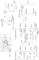
- mapping function (generically, i.e. used for simplicity of elucidation) of a convex shape in a normalized luminance (or brightness) plot, as shown in Fig. 1D .
- Both input and output luminances are defined here on a range normalized to a maximum equaling one, but one must mind that on the input axis this one corresponds to e.g. 5000 nit, and on the output axis e.g. 200 nit (which to and fro can be easily implemented by division respectfully multiplication).
- the darkest colors will typically be too dark for the grading with the lower dynamic range of the two images (here for down-conversion shown on the vertical output axis, of normalized output luminances L_out, the horizontal axis showing all possible normalized input luminances L_in).
- Ergo to have a satisfactory output image corresponding to the input image, we must relatively boost those darkest luminances, e.g. by multiplying by 3x, which is the slope of this luminance compression function F_comp for its darkest end. But one cannot boost forever if one wants no colors to be clipped to maximum output, ergo, the curve must get an increasingly lower slope for brighter input luminances, e.g. it may typically map input 1.0 to output 1.0. In any case the luminance compression function F_comp for down-grading will lie above the 45 degree diagonal (diag) typically.
- the general desired shape for the brightening of the colors may still be the function F_comp (e.g. determined by the video creator, when grading a secondary image corresponding to his master HDR image already optimally graded), one wants a more savvy down-mapping.
- F_comp e.g. determined by the video creator, when grading a secondary image corresponding to his master HDR image already optimally graded
- Fig. 1B for many scenarios one may desire a re-grading which merely changes the brightness of the normalized luminance component (L), but now the innate type of color, i.e. its chromaticity (hue and saturation). If both SDR and HDR are represented with the same red, green and blue color primaries, they will have a similarly shaped gamut tent, only one being higher than the other in absolute luminance representation.
- both gamuts will exactly overlap.
- the desired mapping from a HDR color C_H to a corresponding output SDR color C_L (or vice versa) will simply be a vertical shifting, whilst the projection to the chromaticity plane circle stays the same.
- communication image Im_comm instead of just making some final secondary grading from the master image, e.g. in a television, one can make a lower dynamic range image version for communication, communication image Im_comm.
- this image was defined with its communication image maximum luminance ML_C equal to 200 nit.
- the original 5000 nit image can then be reconstructed (a.k.a. decoded) as a reconstructed image Rec_HDR (i.e.
- the image can be tuned for any possible connected tv, i.e. any ML_D, because one can double the function of the coding function FL_enc as some guidance function for the up-mapping from 100 nit Im_comm not to a 5000 nit reconstructed image, but to e.g. a 1500 nit image.
- the concave function which is substantially the inverse of F_comp (note, for display tuning there is no requirement of exact inversion as there is for reconstruction), will now have to be scaled to be somewhat less steep (i.e.
- a display adapted luminance mapping function FL_DA will be calculated), since we expand to only 1500 nit instead of 5000 nit.
- an image of tertiary dynamic range (DR_T) can be calculated, e.g. optimized for a particular display in that the maximum luminance of that tertiary dynamic range is typically the same as the maximum displayable luminance of a particular display.
- LCD tv mobile phone, home cinema projector, professional movie theatre digital projector
- video different sources and communication media such as OTT, streaming over 5G
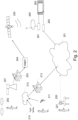
- Fig. 2 shows -in general, without desiring to be limiting- a few typical creations of video where the present teachings may be usefully deployed.
- an intermediate dynamic range format calculate and format all the needed metadata, convert to some broadcasting format like DVB or ATSC, packetize in chunks for distribution, etc. (the etc. indicating there may be tables added for signaling available content, sub-titling, encryption, but at least some of that will be of lesser interest to understand the details of the present technical innovations).
- the video (a television broadcast in the example) is communicated via a television satellite 250 to a satellite dish 260 and a satellite signal capable set-top-box 261. Finally it will be displayed on an end-user display 263.
- This display may be showing this first video, but it may also show other video feed, potentially even at the same time, e.g. in Picture-in-Picture windows (or some data of the first HDR video program may come via some distribution mechanism and other data via another).
- a third example is consumer video production.
- the user will have e.g. when making a vlog a ring lighter 221, and will capture via a mobile phone 220, but (s)he may also be capturing in some exterior location without supplementary lighting. She/he will typically also upload to the internet, but now maybe to youtube, or tiktok, etc.
- the display 263 In case of reception via the internet, the display 263 will be connected via a modem, or router 262 or the like (more complicated setups like in-house wifi and the like are not shown in this mere elucidation).
- the system would work nicely if one stayed in the same 3 primary basis, e.g. the EBU primaries used in the SDR system. But in addition to brighter colors, one also wanted more colorful (i.e. saturated) colors. Therefore one needs to define, process, etc. the colors in a wider circle of the type as shown in Fig. 1B , or in fact a different wider triangle defined by three more saturated red, green and blue primaries (e.g. lasers, or the like). It is not easy to make such displays, and despite a larger color plane Rec. 2020 was defined, not all displays are capable of displaying such highly saturated colors yet.
- the EBU triangle is indeed somewhat limited e.g. in the cyan region, so if one wants to show a sorcerer throwing cyan plasma flames, that may be more beautiful in Rec. 2020, or P3 RGB primaries which are also more saturated.
- chromatic gamut mapping can comprise several sub-steps.
- the red chromaticity as projected in the ground plane of zero luminance corresponds to the 3D red primary, e.g. narrow red primary Pr_N of the 3 defining primaries narrow red primary Pr_N, narrow green primary Pg_N and narrow blue primary Pb_N of the narrow chromatic gamut, and similar for the 3 defining primaries wide red primary Pr_W, wide green primary Pg_W and wide blue primary Pb_W of the wide chromatic gamut. So the luminance-normalized 3-dimensional narrow chromatic gamut (Gam_N) and wide chromatic gamut (Gam_W) may have different shapes and/or orientation.
- the narrower gamut may have already moved inwards considerably, necessitating a significant desaturation, especially if there are many out of gamut colors. So one may want to balance a smaller hue error (by moving the color to the actual, hue-shifted extremity of the narrower gamut), with some desaturation error. What is also schematically shown is that there may be some luminance changes involved in the non-linear projection (fitting) to the narrower gamut. E.g.
- original/input second gamut color Cg2_1 may project (as seen from first mapping arrow FGM_1) upwards to brighter luminance to corresponding output first gamut color Cg1_1, but second input second gamut color Cg2_2 may project upwards to darker luminance to corresponding second output first gamut color Cg1_2 (by second mapping arrow FGM_2, which may be the result of a number of mathematical operations, e.g. first an optimal hue shift, then a combined saturation-luminance projection, etc.).
- chromatic gamut mapping functions are uni-directional. Errors may occur, e.g. one may map a number of highly saturated red colors in the larger gamut onto the same red output color in the narrower color.
- the decoder should undo the dynamic range luminance mapping, but also the chromatic gamut mapping, to reconstruct the SDR-EBU communicated image pixel colors into the original high quality HDR-Rec.2020 colors, also the gamut mapping should be an invertible gamut mapping.
- mapping can be designed, e.g. we teach one in the ETSI TS 103433 standard.
- the color for the HDR reconstruction scenario may be Cg1_2.
- any luminance mapping for any dynamic range change scenario corresponds to a change in vertical position in the normalized gamut.
- the higher/brighter color Cg1_1 may be the color which is corresponding in a e.g. 700 nit TV display tuned image (in a normalized representation, even if one wants to render -which would not always be the case- exactly the same color, e.g. a certain pink of 100 nit, then the relative height for a gamut in which the maximum corresponds to 200 nit should be half as high as a normalized gamut where "1" means only 100 nit.
- the saturation multiplier calculation circuit (432) is arranged to yield as the first factor a display-tuned saturation multiplier (gS_DT) corresponding to the value of the display maximum luminance (ML_D) by applying an equation which raises the reciprocal value to a power C, where C is defined as 1 minus [invPQ(ML_D)-invPQ(ML_low)]/ [invPQ(MDWPL)-invPQ(ML_low)], wherein ML-low is a maximum luminance of the lower luminance dynamic range (DR_L), and invPQ is the inverse function of the SMPTE 2084 Perceptual Quantizer EOTF, for display tuning to lower dynamic range than the second luminance dynamic range (DR_H).
- C is defined as 1 minus [invPQ(ML_D)-invPQ(ML_low)]/ [invPQ(MDWPL)-invPQ(ML_low)]
- ML-low is a maximum luminance of the lower
- the saturation multiplier calculation circuit (432) is arranged to yield the display-tuned saturation multiplier (gS_DT) corresponding to the value of the display maximum luminance (ML_D) by applying an equation which yields the display-tuned saturation multiplier (gS_DT) equal to [invPQ(ML_D)-invPQ(ML_low)]/[ invPQ(MDWPL)-invPQ(ML_low)]+ inv_gS* [invPQ(MDWPL)-invPQ(ML_D)]/[ invPQ(MDWPL)-invPQ(ML_low)].
- the saturation multiplier calculation circuit (432) arranged to calculate the second factor as, for any value of the secondary luma (Yin_HDR), a ratio (gTM_YH) of an output of the luma mapper (431) for that value of the secondary luma (Yin_HDR) divided by that value of the secondary luma (Yin_HDR).
- some embodiments of the apparatus use as the function of the first factor (SF1) and the second factor (SF2) a simple multiplication of the first factor (SF1) by the second factor (SF2).
- a method of calculating a tertiary image (Im_MDR) having a tertiary luminance dynamic range (DR_T), comprises:
- the method has the saturation multiplier calculation arranged to calculate as the first factor a reciprocal value (inv_gS) of a value of the output of the saturation change function (F_S L2H) for an input being the corresponding value of the input luma (Yin_LDR).
- the method has the saturation multiplier calculation arranged to yield as the first factor a display-tuned saturation multiplier (gS_DT) corresponding to the value of the display maximum luminance (ML_D) by applying an equation which raises the reciprocal value to a power C, where C is defined as 1 minus [invPQ(ML_D)-invPQ(ML_low)]/ [invPQ(MDWPL)-invPQ(ML_low)], wherein ML-low is a maximum luminance of the lower luminance dynamic range (DR_L), and invPQ is the inverse function of the SMPTE 2084 Perceptual Quantizer EOTF, for display tuning to lower dynamic range than the second luminance dynamic range (DR_H).
- gS_DT display-tuned saturation multiplier
- the method has the saturation multiplier calculation arranged to yield the display-tuned saturation multiplier (gS_DT) corresponding to the value of the display maximum luminance (ML_D) by applying an equation which yields the display-tuned saturation multiplier (gS_DT) equal to [invPQ(ML_D)-invPQ(ML_low)]/[ invPQ(MDWPL)-invPQ(ML_low)]+ inv_gS*[invPQ(MDWPL)-invPQ(ML_D)]/[ invPQ(MDWPL)-invPQ(ML_low)].
- the method has the saturation multiplier calculation arranged to calculate the second factor as, for any value of the secondary luma (Yin_HDR), a ratio (gTM_YH) of a display tuned luma which results from the luma mapping for that value of the secondary luma (Yin_HDR), divided by that value of the secondary luma (Yin_HDR).
- the method uses as the function of the first factor (SF1) and the second factor (SF2) a multiplication of the first factor (SF1) by the second factor (SF2).
- the HDR video signal decoder (401) is of a type we have elucidated before, e.g. in ETSI TS 103433.
- ETSI TS 103433 For completeness we describe another embodiment of a universal luma and chroma mapper which can be used both in encoding and decoding setting (i.e. downwards respectively upwards mapping, as the case may be) in Fig. 5 , which block can be configured e.g. by connecting it when needed, activated as a software sub-program, etc.
- the universal decoder (500) of Fig. 5 receives the three color components of a pixel being processed, i.e. of a scan through an image, namely luma Y_in and chroma components Cb_in and Cr_in. It has two chroma injection blocks into the luma path, front injector 502 and back injector 506, which can be configured with appropriate coefficients, front end coefficients N1 and N2 respectively back end coefficients M1 and M2, which may either be pre-fixed for some usage, or communicated from an outside source, such as the computer of the video creator, e.g. as metadata attached to a communicated video signal which also contains the YCbCr pixel colors.
- the circuit is configured so that there is injection only at one side, i.e. the front respectively the back, by setting the other side coefficients equal to zero.
- the front injector is typically set to zero, and the back injector may exist, but may also not be present (i.e. also back end coefficients being set to zero).
- the front injector if activated, may add a chroma-dependent extra contribution to the luma component before it is processed, i.e. one can vary the achromatic luma by some value which depends on the Cb and Cr value of the pixel color being processed.
- Y_addF max 0 , N 1 ⁇ Cb + N 2 ⁇ Cr
- Y_addB max(0, M1*Cb+M2*Cr), although this value is typically subtracted from the mapped luma outputted from luma mapper 505 (via back end adder 507, the counterpart of front end adder 501).
- Luma mapper 505 may be supplied with a configurable luma mapping function F_L (e.g. a function directly read from metadata, calculated internally e.g. by a display tuning algorithm, etc.).
- F_L a configurable luma mapping function
- a luma mapping, on achromatic colors can implement a luminance mapping, by virtue of the relationship between luminances and their luma codes as defined by an electable SDR or HDR Electro-optical Transfer Function (or its inverse an OETF).
- the Perceptual Quantizer HDR EOTF as standardized in SMPTE 2084 can be used, or a psychovisually uniformized partially logarithmic EOTF as defined in ETSI TS 103433.
- the luma mapper (402) of the decoder 401 will be pre-loaded with the function needed to map the input lumas Yin_LDR (e.g. 100 nit maximum-defined lumas) to the range of reconstructed master HDR lumas (i.e. Yin_HDR reaching up to e.g. 5000 nit, or 1000 nit, etc.).
- This function is typically directly received in the metadata (MET) part of the HDR image signal S_inp, namely luma mapping function F_L_L2H.
- the pixellated image itself is an array of pixel color triplets Yin_LDR, CbLDR_709 and CrLDR_709 (i.e. the narrow range chromas being defined typically as in the example of Fig. 4 though not exclusively/mandatory in the SDR Rec. 709 a.k.a. EBU gamut).
- the chroma modifier circuit 403 will function as explained with Fig. 5 and use as guiding function F_Sguid the saturation change function (F_S_L2H) function received in metadata, via image input 404 (which also receives the input image Im_inp, which is the communication image Im_comm). It will process the pixel color components as received in the input image, i.e. the communication image, i.e.
- LDR luma Yin_LDR and narrow gamut blue and red chromas Cb_LDR_709 and Cr_LDR_709 typically defined in the ITU Rec. 709 primaries.
- the metadata will typically also comprise a mastering display white point luminance (MDWPL) which describes the HDR characeteristics of the co-communicated pixel color arrays (of which the co-coordinated lumas will normally not define a higher pixel luminance than MDWPL, and typically at least a few scenes of the video will comprise some pixels as bright as MDWPL, e.g. the bulb of a street light). In the case of LDR proxy communication this also coordinates with the F_L_L2H function.
- MDWPL mastering display white point luminance
- This MDWPL metadatum will typically be needed to do smart image processing related to the luminance distribution graded in the master HDR grading, e.g., in the examples below it is used for both optimally display tuning the luma mapping function and the chroma processing, for any connected or connectable display.
- a number indicator (EOTF_nr) of the EOTF which defines the luma code value for all pixel luminances up to MDWPL (and potentially beyond, but as said although codeable those values would typically not occur in the pixel color array), e.g. the value "16" may indicate the perceptual quantizer was used.
- the resulting (intermediate) output color of the decoder 401 is a HDR color (i.e. normalized the various image object normalized lumas have a redistributed position, and translated via the EOTF and the MDWPL value they are the correct reconstructed output luminances of the tertiary image being a wide chromatic gamut HDR image, i.e. luminances correctly scaled along the DR_H up to e.g. 5000 nit), but, it is still in a narrow chromatic gamut (i.e. bright yet relatively less strongly saturated colors, in practice most real world colors will be representable or reasonably approximated, but not e.g. strong yellows, purples or cyans, which are typical subtractive colors).
- a HDR color i.e. normalized the various image object normalized lumas have a redistributed position, and translated via the EOTF and the MDWPL value they are the correct reconstructed output luminances of the terti
- these intermediate HDR colors are inputted to an inverse gamut mapper (410), to obtain as secondary colors the reconstructed wide chromatic gamut HDR colors of the secondary image Im_Sec (Yin_HDR, Cb_LDR_WG and Cr_LDR_WG).
- An example of such a wider, more saturated chromatic gamut is the Rec. 2020 chromaticity primaries color gamut, or the P3 gamut of digital cinema being another useful example.
- This gamut mapper typically increases the saturation of all colors in the narrower chromatic gamut so that more saturated colors in the wider chromatic gamut outside the narrower gamut are obtained (typically by e.g.
- invertible gamut mappings i.e. the decoder moves pixel hues, saturations and lumas over exactly the same path and distance as the encoder but in the opposite direction
- the encoder will do the two steps in the opposite order, i.e. first (forward) gamut mapping, and then the inverse of the LDR-to-HDR decoder, i.e. a HDR-to-LDR encoder.
- first (forward) gamut mapping i.e. a HDR-to-LDR encoder.
- the decoder first do the inverse gamut mapping (IGM), and then the decoding, as that would make some aspects and in particular display tuning easier, but that may pose other issues.
- IGM inverse gamut mapping
- the luma mapping part can, after forward gamut mapping, behave just as if there was only a narrow chromatic HDR signal, and nothing else. So it behaves typical, as if there was no gamut mapping need. That also would allow more liberally incorporation of various kinds of invertible gamut mapping (i.e. with different color projection rationale and corresponding math into the narrower gamut).
- the calculation of the display tuned luma mapping function FL_DT which will be sent to the luma mapper 431 of the display tuning circuit 430 as a loadable luma mapping function (i_FT), may happen as follows. It may e.g. be a lookup table configuration, which can be re-set per image, because all pixels of the present image should be processed with it, but the next picture (e.g. of a totally different HDR scene luma distribution) may need a different function and LUT filling.
- a typical algorithm for constructing a similarly shaped display-tuned function can work as follows: One runs through all possible input values which correspond to points on the 45 degree diagonal (e.g. specifically the point Ptdg shown as a triangle). From that point a line segment (PepL) is drawn e.g. typically orthogonal to the diagonal, until it reaches a point on the input function (the input function point PtFi shown as a diamond on the input curve being the 45 degree diagonal-mirrored version of the input function F_L_L2H).
- PepL line segment
- a distance is calculated starting from the point Ptdg based on a metric which uses as a location value which depends on a ratio of the ML_D versus the input HDR image maximum luminance, compared to a ratio of the maximum luminances of the higher and lower dynamic range reference gradings, i.e. the reconstructed HDR master respectively the input image (ImComm).
- a metric may e.g. be logarithmically, and yield some point in the middle (let's say for a particular ML_D value the position from Ptdg lies on 40% of the total distance of Ptdg to PtFi), namely output function point PtFo.
- ML_D may be obtained from a storage memory 421, e.g. internal in a display if the whole processing chain resides in the display, or from an external display if the processing circuitry resides in an external device, such as a computer preparing the video for a display, or a set-top-box, etc.
- the novel display tuning circuit (430) will be further elucidated also with the aid of Fig. 6 , which gives internal details of a typical advantageous embodiment.
- the luma mapper (431) has already been explained, and is a typical (achromatic) luma mapper, which may be embodied as a single block with a final sole to be applied luma mapping LUT (F_L), or a cascade of successive mapping circuits.
- the more challenging part is the tuning of the chromatic aspect of the pixel colors.
- a display tuner chroma to luma injector 438 and adder 439 may optionally be present, to subtract a display tuned amount in a manner similar as described with aid of Fig. 5 .
- a display formatter 440 may convert the display tuned color components of the pixels of display tuned image Im_MDR (display tuned luma Y_MDR, and chromas Cb_MDR_WG, Cr_MDR_W) to any format preferred by a connectable or connected display, e.g. in RGB format RGB_d, in which e.g. the red, green and blue component may be Perceptual Quantizer 10 bit non-linear red, green and blue color codes.
- this unit may employ a pre-calculated inverse saturation function LUT, and simply establish the corresponding inv_gS output for any Yin_LDR input. Because of the relationship between Yin_LDR and Yin_HDR, which is also fixed for at least one image, one can also precalculate a LUT which has the Yin_HDR pixel lumas as input, for processing all pixels of the current image.
- this basis multiplier inv_gS is display tuned by reference saturation tuning circuit 622, yielding a display tuned basis multiplier gs_DT which will function as a first factor SF1 in the calculation of the total, composite saturation multiplier gsat.
- DR_L lower luminance dynamic range
- gs _ DT invPQ ML _ D ⁇ invPQ ML _ low / invPQ MDWPL ⁇ invPQ ML _ low + inv _ gS ⁇ invPQ MDWPL ⁇ invPQ ML _ D / invPQ MDWPL ⁇ invPQ ML _ low
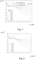
- Fig. 7 shows a set of display tuned saturation multiplier functions obtained by Eqs. 2.
- the largest saturation change is obtained by first function F_S_H2M_100, which may e.g. be the starting (guiding) function for re-grading the reconstructed master HDR chromas to output chromas of a 100 nit LDR image (i.e., this would correspond to the inverse of F_S_L2H).
- Second function F_S_H2M_200 specifies the saturation change, yielding corresponding display tuned basis multiplier gs_DT for any input pixel luma, tuned for obtaining a 200 nit maximum luminance medium dynamic range (MDR) optimized output image (i.e. Im_MDR), etc.
- MDR maximum luminance medium dynamic range
- Fig. 8 shows the same when using Eq. 3 in the chroma display tuning algorithm, which as can be seen gives substantially the same results.
- luminance compensating chroma changing circuit 610 gets both the pixel's HDR luma Yin_HDR and the display tuned luma Y_MDR, i.e. the tertiary luma (which may be passed through from luma mapper 431) as input.
- the second factor SF2 will typically be a tone mapping dependent second luma multiplier gTM_YH which equals the ratio of Y_MDR divided by Yin_HDR.
- the total composite chroma multiplier gsat which is to be used for obtaining the display tuned output chromas is determined by multiplier 640 to be the multiplication of the first factor SF1 by the second factor SF2.
- the whole chroma processing's saturation multiplier (gsat) calculation can be performed on a single pre-calculated LUT, which can get Yin_HDR as input.
- the circuit 432 in such an embodiment will get, before starting processing the pixels of at least one image (and potentially a set of images having the same luminance and saturation mapping functions), the correct LUT TOTLUT[] to apply signaled as sig_TOTLUT from e.g. firmware running outside the color processing core circuit.
- the algorithmic components disclosed in this text may (entirely or in part) be realized in practice as hardware (e.g. parts of an application specific integrated circuit) or as software running on a special digital signal processor, or a generic processor, etc.
- the images may be temporarily or for long term stored in various memories, in the vicinity of the processor(s) or remotely accessible e.g. over the internet.
- the computer program product denotation should be understood to encompass any physical realization of a collection of commands enabling a generic or special purpose processor, after a series of loading steps (which may include intermediate conversion steps, such as translation to an intermediate language, and a final processor language) to enter the commands into the processor, and to execute any of the characteristic functions of an invention.
- the computer program product may be realized as data on a carrier such as e.g. a disk or tape, data present in a memory, data travelling via a network connection -wired or wireless-.
- characteristic data required for the program may also be embodied as a computer program product.
- Some of the technologies may be encompassed in signals, typically control signals for controlling one or more technical behaviors of e.g. a receiving apparatus, such as a television.
- Some circuits may be reconfigurable, and temporarily configured for particular processing by software.
Landscapes
- Engineering & Computer Science (AREA)
- Multimedia (AREA)
- Signal Processing (AREA)
- Processing Of Color Television Signals (AREA)
Priority Applications (2)
| Application Number | Priority Date | Filing Date | Title |
|---|---|---|---|
| EP23204406.5A EP4542985A1 (de) | 2023-10-18 | 2023-10-18 | Luminanz- und farbverarbeitung für hdr-bereichsanpassung |
| PCT/EP2024/078124 WO2025082775A1 (en) | 2023-10-18 | 2024-10-07 | Hdr range adaptation luminance and color processing |
Applications Claiming Priority (1)
| Application Number | Priority Date | Filing Date | Title |
|---|---|---|---|
| EP23204406.5A EP4542985A1 (de) | 2023-10-18 | 2023-10-18 | Luminanz- und farbverarbeitung für hdr-bereichsanpassung |
Publications (1)
| Publication Number | Publication Date |
|---|---|
| EP4542985A1 true EP4542985A1 (de) | 2025-04-23 |
Family
ID=88417507
Family Applications (1)
| Application Number | Title | Priority Date | Filing Date |
|---|---|---|---|
| EP23204406.5A Withdrawn EP4542985A1 (de) | 2023-10-18 | 2023-10-18 | Luminanz- und farbverarbeitung für hdr-bereichsanpassung |
Country Status (2)
| Country | Link |
|---|---|
| EP (1) | EP4542985A1 (de) |
| WO (1) | WO2025082775A1 (de) |
Citations (3)
| Publication number | Priority date | Publication date | Assignee | Title |
|---|---|---|---|---|
| WO2017108906A1 (en) | 2015-12-21 | 2017-06-29 | Koninklijke Philips N.V. | Optimizing high dynamic range images for particular displays |
| WO2017157977A1 (en) | 2016-03-18 | 2017-09-21 | Koninklijke Philips N.V. | Encoding and decoding hdr videos |
| EP3809698A1 (de) * | 2018-07-05 | 2021-04-21 | Huawei Technologies Co., Ltd. | Videosignalsteuerungsverfahren und -apparat |
-
2023
- 2023-10-18 EP EP23204406.5A patent/EP4542985A1/de not_active Withdrawn
-
2024
- 2024-10-07 WO PCT/EP2024/078124 patent/WO2025082775A1/en active Pending
Patent Citations (3)
| Publication number | Priority date | Publication date | Assignee | Title |
|---|---|---|---|---|
| WO2017108906A1 (en) | 2015-12-21 | 2017-06-29 | Koninklijke Philips N.V. | Optimizing high dynamic range images for particular displays |
| WO2017157977A1 (en) | 2016-03-18 | 2017-09-21 | Koninklijke Philips N.V. | Encoding and decoding hdr videos |
| EP3809698A1 (de) * | 2018-07-05 | 2021-04-21 | Huawei Technologies Co., Ltd. | Videosignalsteuerungsverfahren und -apparat |
Non-Patent Citations (2)
| Title |
|---|
| "High-Performance Single Layer High Dynamic Range (HDR) System for use in Consumer Electronics devices; Part 1: Directly Standard Dynamic Range (SDR) Compatible HDR System (SL-HDR1)", vol. JTC BROADCAS EBU/CENELEC/ETSI on Broadcasting, no. V1.2.2, 17 June 2019 (2019-06-17), pages 1 - 125, XP014345447, Retrieved from the Internet <URL:docbox.etsi.org/Broadcast/Broadcast/70-Drafts/00051-1/JTC-051-1v122.docx> [retrieved on 20190617] * |
| DAI MIN (MAGGIE) ET AL: "An overview of end-to-end HDR", PROCEEDINGS OF SPIE; [PROCEEDINGS OF SPIE ISSN 0277-786X VOLUME 10524], SPIE, US, vol. 10752, 17 September 2018 (2018-09-17), pages 107520Z - 107520Z, XP060110666, ISBN: 978-1-5106-1533-5, DOI: 10.1117/12.2322600 * |
Also Published As
| Publication number | Publication date |
|---|---|
| WO2025082775A1 (en) | 2025-04-24 |
Similar Documents
| Publication | Publication Date | Title |
|---|---|---|
| US10964248B2 (en) | Optimized decoded high dynamic range image saturation | |
| EP3381179B1 (de) | Handhabung mehrerer hdr-bildquellen | |
| US11451756B2 (en) | Gamut mapping for HDR (de)coding | |
| US11272195B2 (en) | Multi-range HDR video coding | |
| US10937135B2 (en) | Saturation processing specification for dynamic range mappings | |
| US20170223367A1 (en) | Saturation processing specification for dynamic range mappings | |
| WO2019170465A1 (en) | Versatile dynamic range conversion processing | |
| JP7300070B2 (ja) | 飽和色のための改善されたhdrカラー処理 | |
| US12462360B2 (en) | Display-optimized HDR video contrast adaptation | |
| EP3621307A1 (de) | Mehrbereichige hdr-videocodierung | |
| EP4542985A1 (de) | Luminanz- und farbverarbeitung für hdr-bereichsanpassung | |
| US12541830B2 (en) | Display-optimized ambient light HDR video adapation | |
| EP4636683A1 (de) | Verbesserte luma- und chroma-kartierung für bilder | |
| EP4607917A1 (de) | Verbesserte codierung und decodierung für bilder | |
| EP4567783A1 (de) | Bildanzeigeverbesserung in aufgehellten betrachtungsumgebungen | |
| US12462359B2 (en) | Display-optimized HDR video contrast adaptation | |
| EP4657423A1 (de) | Visuelle zustandsabhängige koordinierte luminanzverarbeitung von assets | |
| WO2025176561A1 (en) | Luminance mapping for images | |
| WO2025040639A1 (en) | Hdr format conversion for processing |
Legal Events
| Date | Code | Title | Description |
|---|---|---|---|
| PUAI | Public reference made under article 153(3) epc to a published international application that has entered the european phase |
Free format text: ORIGINAL CODE: 0009012 |
|
| STAA | Information on the status of an ep patent application or granted ep patent |
Free format text: STATUS: THE APPLICATION HAS BEEN PUBLISHED |
|
| AK | Designated contracting states |
Kind code of ref document: A1 Designated state(s): AL AT BE BG CH CY CZ DE DK EE ES FI FR GB GR HR HU IE IS IT LI LT LU LV MC ME MK MT NL NO PL PT RO RS SE SI SK SM TR |
|
| STAA | Information on the status of an ep patent application or granted ep patent |
Free format text: STATUS: THE APPLICATION IS DEEMED TO BE WITHDRAWN |
|
| 18D | Application deemed to be withdrawn |
Effective date: 20251024 |