EP4542850A1 - Motor control system for energizing a low-voltage motor from a high-voltage source - Google Patents
Motor control system for energizing a low-voltage motor from a high-voltage source Download PDFInfo
- Publication number
- EP4542850A1 EP4542850A1 EP24201958.6A EP24201958A EP4542850A1 EP 4542850 A1 EP4542850 A1 EP 4542850A1 EP 24201958 A EP24201958 A EP 24201958A EP 4542850 A1 EP4542850 A1 EP 4542850A1
- Authority
- EP
- European Patent Office
- Prior art keywords
- phase
- voltage
- motor
- duty
- control circuit
- Prior art date
- Legal status (The legal status is an assumption and is not a legal conclusion. Google has not performed a legal analysis and makes no representation as to the accuracy of the status listed.)
- Pending
Links
Images


Classifications
-
- H—ELECTRICITY
- H02—GENERATION; CONVERSION OR DISTRIBUTION OF ELECTRIC POWER
- H02P—CONTROL OR REGULATION OF ELECTRIC MOTORS, ELECTRIC GENERATORS OR DYNAMO-ELECTRIC CONVERTERS; CONTROLLING TRANSFORMERS, REACTORS OR CHOKE COILS
- H02P27/00—Arrangements or methods for the control of AC motors characterised by the kind of supply voltage
- H02P27/04—Arrangements or methods for the control of AC motors characterised by the kind of supply voltage using variable-frequency supply voltage, e.g. inverter or converter supply voltage
- H02P27/06—Arrangements or methods for the control of AC motors characterised by the kind of supply voltage using variable-frequency supply voltage, e.g. inverter or converter supply voltage using DC to AC converters or inverters
- H02P27/08—Arrangements or methods for the control of AC motors characterised by the kind of supply voltage using variable-frequency supply voltage, e.g. inverter or converter supply voltage using DC to AC converters or inverters with pulse width modulation
-
- H—ELECTRICITY
- H02—GENERATION; CONVERSION OR DISTRIBUTION OF ELECTRIC POWER
- H02P—CONTROL OR REGULATION OF ELECTRIC MOTORS, ELECTRIC GENERATORS OR DYNAMO-ELECTRIC CONVERTERS; CONTROLLING TRANSFORMERS, REACTORS OR CHOKE COILS
- H02P27/00—Arrangements or methods for the control of AC motors characterised by the kind of supply voltage
- H02P27/04—Arrangements or methods for the control of AC motors characterised by the kind of supply voltage using variable-frequency supply voltage, e.g. inverter or converter supply voltage
- H02P27/06—Arrangements or methods for the control of AC motors characterised by the kind of supply voltage using variable-frequency supply voltage, e.g. inverter or converter supply voltage using DC to AC converters or inverters
- H02P27/08—Arrangements or methods for the control of AC motors characterised by the kind of supply voltage using variable-frequency supply voltage, e.g. inverter or converter supply voltage using DC to AC converters or inverters with pulse width modulation
- H02P27/085—Arrangements or methods for the control of AC motors characterised by the kind of supply voltage using variable-frequency supply voltage, e.g. inverter or converter supply voltage using DC to AC converters or inverters with pulse width modulation wherein the PWM mode is adapted on the running conditions of the motor, e.g. the switching frequency
-
- B—PERFORMING OPERATIONS; TRANSPORTING
- B60—VEHICLES IN GENERAL
- B60L—PROPULSION OF ELECTRICALLY-PROPELLED VEHICLES; SUPPLYING ELECTRIC POWER FOR AUXILIARY EQUIPMENT OF ELECTRICALLY-PROPELLED VEHICLES; ELECTRODYNAMIC BRAKE SYSTEMS FOR VEHICLES IN GENERAL; MAGNETIC SUSPENSION OR LEVITATION FOR VEHICLES; MONITORING OPERATING VARIABLES OF ELECTRICALLY-PROPELLED VEHICLES; ELECTRIC SAFETY DEVICES FOR ELECTRICALLY-PROPELLED VEHICLES
- B60L15/00—Methods, circuits, or devices for controlling the traction-motor speed of electrically-propelled vehicles
- B60L15/02—Methods, circuits, or devices for controlling the traction-motor speed of electrically-propelled vehicles characterised by the form of the current used in the control circuit
- B60L15/08—Methods, circuits, or devices for controlling the traction-motor speed of electrically-propelled vehicles characterised by the form of the current used in the control circuit using pulses
-
- H—ELECTRICITY
- H02—GENERATION; CONVERSION OR DISTRIBUTION OF ELECTRIC POWER
- H02M—APPARATUS FOR CONVERSION BETWEEN AC AND AC, BETWEEN AC AND DC, OR BETWEEN DC AND DC, AND FOR USE WITH MAINS OR SIMILAR POWER SUPPLY SYSTEMS; CONVERSION OF DC OR AC INPUT POWER INTO SURGE OUTPUT POWER; CONTROL OR REGULATION THEREOF
- H02M1/00—Details of apparatus for conversion
- H02M1/12—Arrangements for reducing harmonics from AC input or output
- H02M1/126—Arrangements for reducing harmonics from AC input or output using passive filters
-
- H—ELECTRICITY
- H02—GENERATION; CONVERSION OR DISTRIBUTION OF ELECTRIC POWER
- H02M—APPARATUS FOR CONVERSION BETWEEN AC AND AC, BETWEEN AC AND DC, OR BETWEEN DC AND DC, AND FOR USE WITH MAINS OR SIMILAR POWER SUPPLY SYSTEMS; CONVERSION OF DC OR AC INPUT POWER INTO SURGE OUTPUT POWER; CONTROL OR REGULATION THEREOF
- H02M1/00—Details of apparatus for conversion
- H02M1/44—Circuits or arrangements for compensating for electromagnetic interference in converters or inverters
-
- H—ELECTRICITY
- H02—GENERATION; CONVERSION OR DISTRIBUTION OF ELECTRIC POWER
- H02M—APPARATUS FOR CONVERSION BETWEEN AC AND AC, BETWEEN AC AND DC, OR BETWEEN DC AND DC, AND FOR USE WITH MAINS OR SIMILAR POWER SUPPLY SYSTEMS; CONVERSION OF DC OR AC INPUT POWER INTO SURGE OUTPUT POWER; CONTROL OR REGULATION THEREOF
- H02M7/00—Conversion of AC power input into DC power output; Conversion of DC power input into AC power output
- H02M7/42—Conversion of DC power input into AC power output without possibility of reversal
- H02M7/44—Conversion of DC power input into AC power output without possibility of reversal by static converters
- H02M7/48—Conversion of DC power input into AC power output without possibility of reversal by static converters using discharge tubes with control electrode or semiconductor devices with control electrode
- H02M7/53—Conversion of DC power input into AC power output without possibility of reversal by static converters using discharge tubes with control electrode or semiconductor devices with control electrode using devices of a triode or transistor type requiring continuous application of a control signal
- H02M7/537—Conversion of DC power input into AC power output without possibility of reversal by static converters using discharge tubes with control electrode or semiconductor devices with control electrode using devices of a triode or transistor type requiring continuous application of a control signal using semiconductor devices only, e.g. single switched pulse inverters
- H02M7/5387—Conversion of DC power input into AC power output without possibility of reversal by static converters using discharge tubes with control electrode or semiconductor devices with control electrode using devices of a triode or transistor type requiring continuous application of a control signal using semiconductor devices only, e.g. single switched pulse inverters in a bridge configuration
-
- H—ELECTRICITY
- H02—GENERATION; CONVERSION OR DISTRIBUTION OF ELECTRIC POWER
- H02M—APPARATUS FOR CONVERSION BETWEEN AC AND AC, BETWEEN AC AND DC, OR BETWEEN DC AND DC, AND FOR USE WITH MAINS OR SIMILAR POWER SUPPLY SYSTEMS; CONVERSION OF DC OR AC INPUT POWER INTO SURGE OUTPUT POWER; CONTROL OR REGULATION THEREOF
- H02M7/00—Conversion of AC power input into DC power output; Conversion of DC power input into AC power output
- H02M7/42—Conversion of DC power input into AC power output without possibility of reversal
- H02M7/44—Conversion of DC power input into AC power output without possibility of reversal by static converters
- H02M7/48—Conversion of DC power input into AC power output without possibility of reversal by static converters using discharge tubes with control electrode or semiconductor devices with control electrode
- H02M7/53—Conversion of DC power input into AC power output without possibility of reversal by static converters using discharge tubes with control electrode or semiconductor devices with control electrode using devices of a triode or transistor type requiring continuous application of a control signal
- H02M7/537—Conversion of DC power input into AC power output without possibility of reversal by static converters using discharge tubes with control electrode or semiconductor devices with control electrode using devices of a triode or transistor type requiring continuous application of a control signal using semiconductor devices only, e.g. single switched pulse inverters
- H02M7/539—Conversion of DC power input into AC power output without possibility of reversal by static converters using discharge tubes with control electrode or semiconductor devices with control electrode using devices of a triode or transistor type requiring continuous application of a control signal using semiconductor devices only, e.g. single switched pulse inverters with automatic control of output wave form or frequency
- H02M7/5395—Conversion of DC power input into AC power output without possibility of reversal by static converters using discharge tubes with control electrode or semiconductor devices with control electrode using devices of a triode or transistor type requiring continuous application of a control signal using semiconductor devices only, e.g. single switched pulse inverters with automatic control of output wave form or frequency by pulse-width modulation
-
- H—ELECTRICITY
- H02—GENERATION; CONVERSION OR DISTRIBUTION OF ELECTRIC POWER
- H02P—CONTROL OR REGULATION OF ELECTRIC MOTORS, ELECTRIC GENERATORS OR DYNAMO-ELECTRIC CONVERTERS; CONTROLLING TRANSFORMERS, REACTORS OR CHOKE COILS
- H02P6/00—Arrangements for controlling synchronous motors or other dynamo-electric motors using electronic commutation dependent on the rotor position; Electronic commutators therefor
- H02P6/08—Arrangements for controlling the speed or torque of a single motor
Definitions
- the present disclosure generally relates to motor control systems and, more particularly, to a motor control system that allows energizing a low-voltage motor from a high-voltage source.
- DC direct current
- these motors can also be costly to manufacture due, at least in part, to the requirements on isolation and dielectric strength of the materials used within the motor, not just due to the voltage rating of the motor, but also high-voltage corona discharge and partial discharge effects.
- the dielectric breakdown voltage of the material is lower, and the partial discharge effect can cause thermal and chemical degradation of isolation materials resulting in unpredictable and deleterious effects.
- a motor control system includes a voltage source, a multi-phase motor, and a motor control circuit.
- the voltage source is configured to supply a voltage at a maximum voltage magnitude.
- the multi-phase motor has a motor voltage rating that is less than the maximum voltage magnitude.
- the multi-phase motor includes a multi-phase stator and a rotor, and each phase of the multi-phase stator is configured to be energized to thereby generate a rotating magnetic field that causes the rotor to rotate.
- the motor control circuit is coupled to the voltage source and to each phase of the multi-phase stator.
- the motor control circuit is configured to energize each phase of the multi-phase stator with a voltage having a peak magnitude at or below the motor voltage rating voltage.
- the motor control circuit includes a multi-phase inverter, a multi-phase output filter circuit, and a duty-cycle control circuit.
- the multi-phase inverter is coupled to the voltage source and is coupled to receive a duty-cycle control signal.
- the multi-phase inverter is configured, in response to the duty-cycle control signal, to generate a plurality of pulse-width-modulated (PWM) voltages, where each PWM voltage has a magnitude based on the duty-cycle control signal.
- PWM pulse-width-modulated
- the multi-phase output filter circuit is coupled to receive the PWM voltages and is configured to supply the voltage to each phase of the multi-phase stator.
- the duty-cycle control circuit is configured to generate and supply the duty-cycle control signal.
- the duty-cycle control signal and the multiphase output filter ensure that the peak magnitude of the voltage supplied to each phase of the multi-phase stator is at or below the motor voltage rating.
- an actuation control system in another embodiment, includes an actuator, a voltage source, a multi-phase motor, and a motor control circuit.
- the actuator is coupled to receive a drive torque and, upon receipt of the drive torque, to move to an actuator position.
- the voltage source is configured to supply a voltage at a maximum voltage magnitude.
- the multi-phase motor has a motor voltage rating that is less than the maximum voltage magnitude.
- the multi-phase motor includes a multi-phase stator and a rotor. The rotor is coupled to the actuator, and each phase of the multi-phase stator is configured to be energized to thereby generate a rotating magnetic field that causes the rotor to rotate and supply the drive torque to the actuator.
- the motor control circuit is coupled to the voltage source and to each phase of the multi-phase stator.
- the motor control circuit is configured to energize each phase of the multi-phase stator with a voltage having a peak magnitude at or below the motor voltage rating voltage.
- the motor control circuit includes a multi-phase inverter, a multi-phase output filter circuit, and a duty-cycle control circuit.
- the multi-phase inverter is coupled to the voltage source and is coupled to receive a duty-cycle control signal.
- the multi-phase inverter is configured, in response to the duty-cycle control signal, to generate a plurality of pulse-width-modulated (PWM) voltages, where each PWM voltage has a magnitude based on the duty-cycle control signal.
- the multi-phase output filter circuit is coupled to receive the PWM voltages and is configured to supply the voltage to each phase of the multi-phase stator.
- the duty-cycle control circuit is configured to generate and supply the duty-cycle control signal.
- the duty-cycle control signal and the multiphase output filter ensure that the peak magnitude of the voltage supplied to each phase of the multi-phase stator is at or below
- an aircraft system in yet another embodiment, includes an aircraft, a voltage source, a multi-phase motor, and a motor control circuit.
- the voltage source is disposed within the aircraft and is configured to supply a voltage at a maximum voltage magnitude.
- the multi-phase motor is disposed within the aircraft and has a motor voltage rating that is less than the maximum voltage magnitude.
- the multi-phase motor includes a multi-phase stator and a rotor, and each phase of the multi-phase stator is configured to be energized to thereby generate a rotating magnetic field that causes the rotor to rotate.
- the motor control circuit is disposed within the aircraft and is coupled to the voltage source and to each phase of the multi-phase stator.
- the motor control circuit is configured to energize each phase of the multi-phase stator with a voltage having a peak magnitude at or below the motor voltage rating voltage.
- the motor control circuit includes a multi-phase inverter, a multi-phase output filter circuit, and a duty-cycle control circuit.
- the multi-phase inverter is coupled to the voltage source and is coupled to receive a duty-cycle control signal.
- the multi-phase inverter is configured, in response to the duty-cycle control signal, to generate a plurality of pulse-width-modulated (PWM) voltages, where each PWM voltage has a magnitude based on the duty-cycle control signal.
- the multi-phase output filter circuit is coupled to receive the PWM voltages and is configured to supply the voltage to each phase of the multi-phase stator.
- the duty-cycle control circuit is configured to generate and supply the duty-cycle control signal.
- the duty-cycle control signal and the multiphase output filter ensure that the peak magnitude of the voltage supplied to each phase of the multi-phase stator is at or below
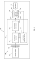
- FIG. 1 a functional block diagram of one embodiment of a motor control system 100 is depicted and includes a voltage source 102, a multi-phase motor 104, and a motor control circuit 106.
- the depicted motor control system 100 is disposed within a vehicle 110.
- the vehicle 110 is an aircraft, such as the example aircraft 110 depicted in FIG. 2 .
- the aircraft 110 depicted in FIG. 2 is configured as an Urban Air Mobility (UAM) aircraft, it could be configured as any one of numerous other types of aircraft.
- UAM Urban Air Mobility
- the voltage source 102 is configured to supply a voltage at a maximum voltage magnitude, and the multi-phase motor 104 has a motor voltage rating that is less than the maximum voltage magnitude.
- the maximum voltage magnitude of the voltage source 102 is at least two times the motor voltage rating. In one particular embodiment, the value of the maximum voltage magnitude is in a range of about 450 VDC to about 900 VDC, and the value of the motor voltage rating is less than about 300 VAC.
- the multi-phase motor 104 includes a multi-phase stator 108 and a rotor 112.
- the multi-phase stator 108 is implemented as a three-phase stator, and thus includes three phases 114-1, 114-2, 114-3. It will be appreciated, however, that in other embodiments, the multi-phase stator 108 could be implemented with more than this number of phases.
- each phase of the multi-phase stator 108 is configured to be energized to thereby generate a rotating magnetic field.
- the rotating magnetic field in turn causes the rotor 112 to rotate and supply a drive torque.
- the motor control circuit 106 is coupled to the voltage source 102 and to each phase 114 of the multi-phase stator 108.
- the motor control circuit 106 is configured to energize each phase 114 of the multi-phase stator 108 with a voltage, thereby generating the rotating magnetic field.
- the voltage supplied by the motor control circuit 106 has a peak magnitude that is at or below the motor voltage rating voltage.
- the motor control circuit 106 includes a multi-phase inverter 116, a multi-phase output filter 118, and a duty-cycle control circuit 122.
- the multi-phase inverter 116 is coupled to the voltage source 102 and is additionally coupled to receive a duty-cycle control signal 124.
- the multi-phase inverter 116 is configured, in response to the duty-cycle control signal, and using known techniques, to generate a plurality of pulse-width-modulated (PWM) voltages.
- PWM pulse-width-modulated
- the multi-phase inverter 116 is configured such that each PWM voltage has a magnitude that is based on the duty-cycle control signal 124.
- the multi-phase inverter 116 may be implemented using any one of numerous known inverter circuit topologies. In one embodiment, such as the one depicted in FIG. 3 , the multi-phase inverter 116 is implemented using a 3-phase inverter.
- the multi-phase output filter circuit 118 is coupled to receive the PWM voltages supplied by the multi-phase inverter 116 and is configured to supply the voltage to each phase 114 of the multi-phase stator 108.
- the multi-phase output filter circuit 118 may be variously implemented, in one particular embodiment, it is implemented as a multi-phase inductor-capacitor (LC) filter circuit.
- LC multi-phase inductor-capacitor
- the duty-cycle control circuit 122 is configured to generate and supply the duty-cycle control signal 124 to the multi-phase inverter 116.
- the duty-cycle control circuit 122 may be implemented or realized with a general purpose processor, a controller, a microprocessor, a microcontroller, a content addressable memory, a digital signal processor, an application specific integrated circuit, a field programmable gate array, any suitable programmable logic device, discrete gate or transistor logic, processing core, discrete hardware components, or any combination thereof, designed to perform the functions described herein.
- the duty-cycle control circuit 122 includes processing logic that may be configured to carry out the functions, techniques, and processing tasks associated with the operation of the motor control system 100, as described herein.
- the steps of a method or algorithm described in connection with the embodiments disclosed herein may be embodied directly in hardware, in firmware, in a software module executed by the duty-cycle control circuit 122, or in any practical combination thereof.
- the duty-cycle control circuit 122 includes or otherwise accesses a data storage element, such as a memory (e.g., RAM memory, ROM memory, flash memory, registers, a hard disk, or the like) or another suitable non-transitory short or long term storage media capable of storing computer-executable programming instructions or other data for execution that, when read and executed by the duty-cycle control circuit 122, cause the duty-cycle control circuit 122 to execute and perform its functions.
- a data storage element such as a memory (e.g., RAM memory, ROM memory, flash memory, registers, a hard disk, or the like) or another suitable non-transitory short or long term storage media capable of storing computer-executable programming instructions or other data for execution that, when read and executed by the duty-cycle control circuit
- computer-executable programming instructions are executed by the processor, control module, or other hardware associated with the duty-cycle control circuit 122 and cause the duty-cycle control circuit 122 to generate the duty-cycle control signal 124 such that the duty-cycle control signal 124, together with the multiphase output filter 118, ensures the peak magnitude of the voltage supplied to each phase 114 of the multi-phase stator 108 is at or below the motor voltage rating.
- the duty-cycle control signal 124 generated by the duty-cycle control circuit 122 may also adjust the PWM voltages supplied by the multi-phase inverter 116 to control the rotational speed of the multi-phase motor 104.
- the motor control system 100 may, in such embodiments, additionally include a rotational speed and/or position sensor 126 that is configured to sense the rotational speed and/or position of the multi-phase motor 104 and supply a speed and/or position signal representative thereof to the duty-cycle control circuit 122.
- the duty-cycle control signal 124 while adjusting the PWM voltages to control motor speed, additionally ensures, together with the with the multiphase output filter 118, that the peak magnitude of the voltage supplied to each phase 114 of the multi-phase stator 108 is at or below the motor voltage rating.
- the motor control system 100 may, at least in the depicted embodiment, additionally include an input filter 128.
- the input filter 128, when included, is coupled between the voltage source 102 and the motor control circuit 106.
- the input filter 128 is configured to at least reduce electromagnetic interference (EMI) that may be present in the voltage supplied from the voltage source 102.
- EMI electromagnetic interference
- the multi-phase motor 108 may be used to drive various loads. In the depicted embodiment, it is used to drive an actuator 132.
- the actuator 132 which may be coupled to any one of numerous devices, such as a valve, a flight control surface, or landing gear, just to name a few, is coupled to the rotor 112 of the multi-phase motor 108, to thereby receive the drive torque from the rotor 112 when the rotor 112 rotates.
- the actuator 132 is depicted separate from the multi-phase motor 104 in FIG. 1 , it will be appreciated that this is done merely for clarity, and that in some embodiments, the multi-phase motor 104 may be implemented as one of the internal parts of the actuator 132.
- the actuator 132 may also include other components, such as gearing, an output shaft, a brake, and a position sensor, just to name a few.
Landscapes
- Engineering & Computer Science (AREA)
- Power Engineering (AREA)
- Transportation (AREA)
- Mechanical Engineering (AREA)
- Physics & Mathematics (AREA)
- Electromagnetism (AREA)
- Control Of Ac Motors In General (AREA)
Abstract
Description
- The present disclosure generally relates to motor control systems and, more particularly, to a motor control system that allows energizing a low-voltage motor from a high-voltage source.
- Many vehicles, including many aircraft, are equipped with relatively high-voltage direct current (DC) power sources. For example, many aircraft include voltage sources that supply voltages in the range of 450-900VDC. The voltage sources are very safe and reliable. However, one potential challenge, especially in the aerospace industry, is that electric motors that are rated for these voltages can be relatively large and heavy, which can adversely impact flight costs.
- In addition, these motors can also be costly to manufacture due, at least in part, to the requirements on isolation and dielectric strength of the materials used within the motor, not just due to the voltage rating of the motor, but also high-voltage corona discharge and partial discharge effects. In particular, at high altitudes, where the air pressure is lower, the dielectric breakdown voltage of the material is lower, and the partial discharge effect can cause thermal and chemical degradation of isolation materials resulting in unpredictable and deleterious effects.
- Hence, it is desirable to provide a way of using motors with lower voltage ratings, while still retaining the relatively high-voltage power sources. The present disclosure addresses at least this need.
- This summary is provided to describe select concepts in a simplified form that are further described in the Detailed Description. This summary is not intended to identify key or essential features of the claimed subject matter, nor is it intended to be used as an aid in determining the scope of the claimed subject matter.
- In one embodiment, a motor control system includes a voltage source, a multi-phase motor, and a motor control circuit. The voltage source is configured to supply a voltage at a maximum voltage magnitude. The multi-phase motor has a motor voltage rating that is less than the maximum voltage magnitude. The multi-phase motor includes a multi-phase stator and a rotor, and each phase of the multi-phase stator is configured to be energized to thereby generate a rotating magnetic field that causes the rotor to rotate. The motor control circuit is coupled to the voltage source and to each phase of the multi-phase stator. The motor control circuit is configured to energize each phase of the multi-phase stator with a voltage having a peak magnitude at or below the motor voltage rating voltage. The motor control circuit includes a multi-phase inverter, a multi-phase output filter circuit, and a duty-cycle control circuit. The multi-phase inverter is coupled to the voltage source and is coupled to receive a duty-cycle control signal. The multi-phase inverter is configured, in response to the duty-cycle control signal, to generate a plurality of pulse-width-modulated (PWM) voltages, where each PWM voltage has a magnitude based on the duty-cycle control signal. The multi-phase output filter circuit is coupled to receive the PWM voltages and is configured to supply the voltage to each phase of the multi-phase stator. The duty-cycle control circuit is configured to generate and supply the duty-cycle control signal. The duty-cycle control signal and the multiphase output filter ensure that the peak magnitude of the voltage supplied to each phase of the multi-phase stator is at or below the motor voltage rating.
- In another embodiment, an actuation control system includes an actuator, a voltage source, a multi-phase motor, and a motor control circuit. The actuator is coupled to receive a drive torque and, upon receipt of the drive torque, to move to an actuator position. The voltage source is configured to supply a voltage at a maximum voltage magnitude. The multi-phase motor has a motor voltage rating that is less than the maximum voltage magnitude. The multi-phase motor includes a multi-phase stator and a rotor. The rotor is coupled to the actuator, and each phase of the multi-phase stator is configured to be energized to thereby generate a rotating magnetic field that causes the rotor to rotate and supply the drive torque to the actuator. The motor control circuit is coupled to the voltage source and to each phase of the multi-phase stator. The motor control circuit is configured to energize each phase of the multi-phase stator with a voltage having a peak magnitude at or below the motor voltage rating voltage. The motor control circuit includes a multi-phase inverter, a multi-phase output filter circuit, and a duty-cycle control circuit. The multi-phase inverter is coupled to the voltage source and is coupled to receive a duty-cycle control signal. The multi-phase inverter is configured, in response to the duty-cycle control signal, to generate a plurality of pulse-width-modulated (PWM) voltages, where each PWM voltage has a magnitude based on the duty-cycle control signal. The multi-phase output filter circuit is coupled to receive the PWM voltages and is configured to supply the voltage to each phase of the multi-phase stator. The duty-cycle control circuit is configured to generate and supply the duty-cycle control signal. The duty-cycle control signal and the multiphase output filter ensure that the peak magnitude of the voltage supplied to each phase of the multi-phase stator is at or below the motor voltage rating.
- In yet another embodiment, an aircraft system includes an aircraft, a voltage source, a multi-phase motor, and a motor control circuit. The voltage source is disposed within the aircraft and is configured to supply a voltage at a maximum voltage magnitude. The multi-phase motor is disposed within the aircraft and has a motor voltage rating that is less than the maximum voltage magnitude. The multi-phase motor includes a multi-phase stator and a rotor, and each phase of the multi-phase stator is configured to be energized to thereby generate a rotating magnetic field that causes the rotor to rotate. The motor control circuit is disposed within the aircraft and is coupled to the voltage source and to each phase of the multi-phase stator. The motor control circuit is configured to energize each phase of the multi-phase stator with a voltage having a peak magnitude at or below the motor voltage rating voltage. The motor control circuit includes a multi-phase inverter, a multi-phase output filter circuit, and a duty-cycle control circuit. The multi-phase inverter is coupled to the voltage source and is coupled to receive a duty-cycle control signal. The multi-phase inverter is configured, in response to the duty-cycle control signal, to generate a plurality of pulse-width-modulated (PWM) voltages, where each PWM voltage has a magnitude based on the duty-cycle control signal. The multi-phase output filter circuit is coupled to receive the PWM voltages and is configured to supply the voltage to each phase of the multi-phase stator. The duty-cycle control circuit is configured to generate and supply the duty-cycle control signal. The duty-cycle control signal and the multiphase output filter ensure that the peak magnitude of the voltage supplied to each phase of the multi-phase stator is at or below the motor voltage rating.
- Furthermore, other desirable features and characteristics of the motor control systems will become apparent from the subsequent detailed description and the appended claims, taken in conjunction with the accompanying drawings and the preceding background.
- The present disclosure will hereinafter be described in conjunction with the following drawing figures, wherein like numerals denote like elements, and wherein:
-
FIG. 1 depicts a functional block diagram of one embodiment of a motor control system; -
FIG. 2 depicts a perspective view of one embodiment of an aircraft; -
FIG.3 depicts a schematic diagram of one embodiment of a multi-phase inverter; and -
FIG. 4 depicts a schematic diagram of one embodiment of a multi-phase LC filter circuit. - The following detailed description is merely exemplary in nature and is not intended to limit the invention or the application and uses of the invention. As used herein, the word "exemplary" means "serving as an example, instance, or illustration." Thus, any embodiment described herein as "exemplary" is not necessarily to be construed as preferred or advantageous over other embodiments. All of the embodiments described herein are exemplary embodiments provided to enable persons skilled in the art to make or use the invention and not to limit the scope of the invention which is defined by the claims. Furthermore, there is no intention to be bound by any expressed or implied theory presented in the preceding technical field, background, brief summary, or the following detailed description.
- Referring first to
FIG. 1 , a functional block diagram of one embodiment of amotor control system 100 is depicted and includes avoltage source 102, amulti-phase motor 104, and amotor control circuit 106. Before proceeding further, it is noted that the depictedmotor control system 100 is disposed within avehicle 110. Although the configuration of thevehicle 110 may vary, in one particular embodiment thevehicle 110 is an aircraft, such as theexample aircraft 110 depicted inFIG. 2 . It should be further noted that although theaircraft 110 depicted inFIG. 2 is configured as an Urban Air Mobility (UAM) aircraft, it could be configured as any one of numerous other types of aircraft. - Returning now to a description of the
motor control system 100, thevoltage source 102 is configured to supply a voltage at a maximum voltage magnitude, and themulti-phase motor 104 has a motor voltage rating that is less than the maximum voltage magnitude. Although the relative values of the maximum voltage magnitude and the motor voltage rating may vary, the maximum voltage magnitude of thevoltage source 102 is at least two times the motor voltage rating. In one particular embodiment, the value of the maximum voltage magnitude is in a range of about 450 VDC to about 900 VDC, and the value of the motor voltage rating is less than about 300 VAC. - The
multi-phase motor 104, as is generally known, includes amulti-phase stator 108 and arotor 112. In the depicted embodiment, themulti-phase stator 108 is implemented as a three-phase stator, and thus includes three phases 114-1, 114-2, 114-3. It will be appreciated, however, that in other embodiments, themulti-phase stator 108 could be implemented with more than this number of phases. - Regardless of the specific number of phases 114, each phase of the
multi-phase stator 108 is configured to be energized to thereby generate a rotating magnetic field. As is generally known, the rotating magnetic field in turn causes therotor 112 to rotate and supply a drive torque. - The
motor control circuit 106 is coupled to thevoltage source 102 and to each phase 114 of themulti-phase stator 108. Themotor control circuit 106 is configured to energize each phase 114 of themulti-phase stator 108 with a voltage, thereby generating the rotating magnetic field. The voltage supplied by themotor control circuit 106 has a peak magnitude that is at or below the motor voltage rating voltage. To implement this functionality, and asFIG. 1 further depicts, themotor control circuit 106 includes amulti-phase inverter 116, amulti-phase output filter 118, and a duty-cycle control circuit 122. - The
multi-phase inverter 116 is coupled to thevoltage source 102 and is additionally coupled to receive a duty-cycle control signal 124. Themulti-phase inverter 116 is configured, in response to the duty-cycle control signal, and using known techniques, to generate a plurality of pulse-width-modulated (PWM) voltages. Specifically, themulti-phase inverter 116 is configured such that each PWM voltage has a magnitude that is based on the duty-cycle control signal 124. It will be appreciated that themulti-phase inverter 116 may be implemented using any one of numerous known inverter circuit topologies. In one embodiment, such as the one depicted inFIG. 3 , themulti-phase inverter 116 is implemented using a 3-phase inverter. - The multi-phase
output filter circuit 118 is coupled to receive the PWM voltages supplied by themulti-phase inverter 116 and is configured to supply the voltage to each phase 114 of themulti-phase stator 108. Although the multi-phaseoutput filter circuit 118 may be variously implemented, in one particular embodiment, it is implemented as a multi-phase inductor-capacitor (LC) filter circuit. One example embodiment of a suitable multi-phaseLC filter circuit 400 is depicted inFIG. 4 . - The duty-
cycle control circuit 122 is configured to generate and supply the duty-cycle control signal 124 to themulti-phase inverter 116. Depending on the embodiment, the duty-cycle control circuit 122 may be implemented or realized with a general purpose processor, a controller, a microprocessor, a microcontroller, a content addressable memory, a digital signal processor, an application specific integrated circuit, a field programmable gate array, any suitable programmable logic device, discrete gate or transistor logic, processing core, discrete hardware components, or any combination thereof, designed to perform the functions described herein. In practice, the duty-cycle control circuit 122 includes processing logic that may be configured to carry out the functions, techniques, and processing tasks associated with the operation of themotor control system 100, as described herein. Furthermore, the steps of a method or algorithm described in connection with the embodiments disclosed herein may be embodied directly in hardware, in firmware, in a software module executed by the duty-cycle control circuit 122, or in any practical combination thereof. In accordance with one or more embodiments, the duty-cycle control circuit 122 includes or otherwise accesses a data storage element, such as a memory (e.g., RAM memory, ROM memory, flash memory, registers, a hard disk, or the like) or another suitable non-transitory short or long term storage media capable of storing computer-executable programming instructions or other data for execution that, when read and executed by the duty-cycle control circuit 122, cause the duty-cycle control circuit 122 to execute and perform its functions. - In exemplary embodiments, computer-executable programming instructions are executed by the processor, control module, or other hardware associated with the duty-
cycle control circuit 122 and cause the duty-cycle control circuit 122 to generate the duty-cycle control signal 124 such that the duty-cycle control signal 124, together with themultiphase output filter 118, ensures the peak magnitude of the voltage supplied to each phase 114 of themulti-phase stator 108 is at or below the motor voltage rating. - It will be appreciated that in some embodiments, the duty-
cycle control signal 124 generated by the duty-cycle control circuit 122 may also adjust the PWM voltages supplied by themulti-phase inverter 116 to control the rotational speed of themulti-phase motor 104. Thus, asFIG. 1 additionally depicts, themotor control system 100 may, in such embodiments, additionally include a rotational speed and/orposition sensor 126 that is configured to sense the rotational speed and/or position of themulti-phase motor 104 and supply a speed and/or position signal representative thereof to the duty-cycle control circuit 122. In such embodiments, the duty-cycle control signal 124, while adjusting the PWM voltages to control motor speed, additionally ensures, together with the with themultiphase output filter 118, that the peak magnitude of the voltage supplied to each phase 114 of themulti-phase stator 108 is at or below the motor voltage rating. - As
FIG. 1 further depicts, themotor control system 100 may, at least in the depicted embodiment, additionally include aninput filter 128. Theinput filter 128, when included, is coupled between thevoltage source 102 and themotor control circuit 106. Theinput filter 128 is configured to at least reduce electromagnetic interference (EMI) that may be present in the voltage supplied from thevoltage source 102. - The
multi-phase motor 108 may be used to drive various loads. In the depicted embodiment, it is used to drive anactuator 132. Theactuator 132, which may be coupled to any one of numerous devices, such as a valve, a flight control surface, or landing gear, just to name a few, is coupled to therotor 112 of themulti-phase motor 108, to thereby receive the drive torque from therotor 112 when therotor 112 rotates. Although theactuator 132 is depicted separate from themulti-phase motor 104 inFIG. 1 , it will be appreciated that this is done merely for clarity, and that in some embodiments, themulti-phase motor 104 may be implemented as one of the internal parts of theactuator 132. Moreover, while not depicted inFIG. 1 , theactuator 132 may also include other components, such as gearing, an output shaft, a brake, and a position sensor, just to name a few. - While at least one exemplary embodiment has been presented in the foregoing detailed description of the invention, it should be appreciated that a vast number of variations exist. It should also be appreciated that the exemplary embodiment or exemplary embodiments are only examples, and are not intended to limit the scope, applicability, or configuration of the invention in any way. Rather, the foregoing detailed description will provide those skilled in the art with a convenient road map for implementing an exemplary embodiment of the invention. It being understood that various changes may be made in the function and arrangement of elements described in an exemplary embodiment without departing from the scope of the invention as set forth in the appended claims.
Claims (5)
- A motor control system, comprising:a voltage source configured to supply a voltage at a maximum voltage magnitude;a multi-phase motor having a motor voltage rating that is less than the maximum voltage magnitude, the multi-phase motor including a multi-phase stator and a rotor, each phase of the multi-phase stator configured to be energized to thereby generate a rotating magnetic field that causes the rotor to rotate; anda motor control circuit coupled to the voltage source and to each phase of the multi-phase stator, the motor control circuit configured to energize each phase of the multi-phase stator with a voltage having a peak magnitude at or below the motor voltage rating voltage, the motor control circuit including:a multi-phase inverter coupled to the voltage source and coupled to receive a duty-cycle control signal, the multi-phase inverter configured, in response to the duty-cycle control signal, to generate a plurality of pulse-width-modulated (PWM) voltages, each PWM voltage having a magnitude based on the duty-cycle control signal,a multi-phase output filter circuit coupled to receive the PWM voltages and configured to supply the voltage to each phase of the multi-phase stator, anda duty-cycle control circuit configured to generate and supply the duty-cycle control signal,wherein the duty-cycle control signal and multiphase output filter ensure the peak magnitude of the voltage supplied to each phase of the multi-phase stator is at or below the motor voltage rating.
- The motor control system of claim 1, wherein the multi-phase output filter circuit comprises an inductor-capacitor (LC) filter.
- The motor control system of claim 1, wherein the maximum voltage magnitude of the voltage source is in a range of about 450VDC to about 900VDC.
- The motor control system of claim 3, wherein the motor voltage rating of the multi-phase motor is less than about 300VAC.
- The motor control system of claim 1, further comprising an input filter coupled between the voltage source and the motor control circuit, the input filter configured to at least reduce electromagnetic interference.
Applications Claiming Priority (1)
| Application Number | Priority Date | Filing Date | Title |
|---|---|---|---|
| US18/487,641 US12445079B2 (en) | 2023-10-16 | 2023-10-16 | Motor control system for energizing a low-voltage motor from a high-voltage source |
Publications (1)
| Publication Number | Publication Date |
|---|---|
| EP4542850A1 true EP4542850A1 (en) | 2025-04-23 |
Family
ID=92895827
Family Applications (1)
| Application Number | Title | Priority Date | Filing Date |
|---|---|---|---|
| EP24201958.6A Pending EP4542850A1 (en) | 2023-10-16 | 2024-09-23 | Motor control system for energizing a low-voltage motor from a high-voltage source |
Country Status (2)
| Country | Link |
|---|---|
| US (1) | US12445079B2 (en) |
| EP (1) | EP4542850A1 (en) |
Citations (1)
| Publication number | Priority date | Publication date | Assignee | Title |
|---|---|---|---|---|
| US6351090B1 (en) * | 1997-10-20 | 2002-02-26 | Aerospatiale Societe Nationale Industrielle And Kollmorgen Artus | Device for starting a gas turbine in an aircraft |
Family Cites Families (14)
| Publication number | Priority date | Publication date | Assignee | Title |
|---|---|---|---|---|
| US5541488A (en) | 1994-04-11 | 1996-07-30 | Sundstrand Corporation | Method and apparatus for controlling induction motors |
| US6262896B1 (en) | 2000-06-19 | 2001-07-17 | General Motors Corporation | Auxiliary power conversion for an electric vehicle using high frequency injection into a PWM inverter |
| JP4329880B1 (en) | 2009-01-14 | 2009-09-09 | トヨタ自動車株式会社 | AC motor control device and electric vehicle |
| IT1394909B1 (en) * | 2009-06-10 | 2012-07-20 | St Microelectronics Srl | SWITCHING METHOD OF A MULTI-PHASE PWM CONVERTER |
| JP5558752B2 (en) * | 2009-07-30 | 2014-07-23 | 日立オートモティブシステムズ株式会社 | Power converter |
| JP5784313B2 (en) | 2011-01-20 | 2015-09-24 | ナブテスコ株式会社 | Motor control device and motor control system |
| US20150349694A1 (en) | 2014-06-03 | 2015-12-03 | Hamilton Sundstrand Corporation | Light weight filter with dc common mode inductor for electric aircraft motor controller |
| JP6838469B2 (en) * | 2017-04-10 | 2021-03-03 | トヨタ自動車株式会社 | Drive device |
| TWI638508B (en) * | 2017-07-21 | 2018-10-11 | 立錡科技股份有限公司 | Multi-phase switching regulator and control circuit and control method thereof |
| US10128758B1 (en) * | 2017-09-19 | 2018-11-13 | Qualcomm Incorporated | Automatic phase current balancing in multi-phase converters |
| KR102712336B1 (en) * | 2018-08-17 | 2024-09-30 | 현대자동차주식회사 | Inverter system for vehicle |
| US11043891B1 (en) * | 2020-01-23 | 2021-06-22 | Hong Kong Applied Science and Technology Research Institute Company Limited | Controller for an AC/DC or a DC/AC multi-phase power converter |
| CN111600464B (en) * | 2020-06-30 | 2023-12-26 | 上海晶丰明源半导体股份有限公司 | Multi-phase power supply dynamic response control circuit and control method |
| CN214380727U (en) | 2021-03-25 | 2021-10-08 | 深圳市兆威机电股份有限公司 | Motor power supply control device and system |
-
2023
- 2023-10-16 US US18/487,641 patent/US12445079B2/en active Active
-
2024
- 2024-09-23 EP EP24201958.6A patent/EP4542850A1/en active Pending
Patent Citations (1)
| Publication number | Priority date | Publication date | Assignee | Title |
|---|---|---|---|---|
| US6351090B1 (en) * | 1997-10-20 | 2002-02-26 | Aerospatiale Societe Nationale Industrielle And Kollmorgen Artus | Device for starting a gas turbine in an aircraft |
Non-Patent Citations (2)
| Title |
|---|
| AUSTIN H BONNETT: "A Comparison Between Insulation Systems Available for PWM-Inverter-Fed Motors", IEEE TRANSACTIONS ON INDUSTRY APPLICATIONS, IEEE SERVICE CENTER, PISCATAWAY, NJ, US, vol. 33, no. 5, 1 October 1997 (1997-10-01), XP011022260, ISSN: 0093-9994 * |
| BONNETT A N: "Insulation systems available for PWM inverter fed motors for low voltage pulp and paper applications", PULP AND PAPER INDUSTRY TECHNICAL CONFERENCE, 1997., ANNUAL CINCINNATI, OH, USA 16-20 JUNE 1997, NEW YORK, NY, USA,IEEE, US, 16 June 1997 (1997-06-16), pages 17 - 28, XP032133504, ISBN: 978-0-7803-3919-4, DOI: 10.1109/PAPCON.1997.595207 * |
Also Published As
| Publication number | Publication date |
|---|---|
| US20250125760A1 (en) | 2025-04-17 |
| US12445079B2 (en) | 2025-10-14 |
Similar Documents
| Publication | Publication Date | Title |
|---|---|---|
| CN114208021B (en) | Motor control devices, mechatronic units, and electric vehicle systems | |
| EP3017517B1 (en) | Motor control for stability and power supply protection | |
| EP2826659B1 (en) | Onboard motor controller | |
| JP5907137B2 (en) | Power conversion device and power conversion system | |
| CN105556826B (en) | Motor drive | |
| JP6715759B2 (en) | Inverter drive device and electric vehicle system using the same | |
| WO2015075883A1 (en) | In-vehicle electric system | |
| WO2016027427A1 (en) | In-vehicle electric motor control device | |
| WO2018142829A1 (en) | Motor drive device and electric power steering device | |
| CN110326202B (en) | Control device and electric power steering device using the same | |
| CN111279607B (en) | Control device for rotating electrical machine | |
| CN108736795A (en) | Series-parallel driving system for electric vehicles | |
| US12445079B2 (en) | Motor control system for energizing a low-voltage motor from a high-voltage source | |
| JP6123731B2 (en) | Electric motor control device | |
| JP5733259B2 (en) | Rotating machine control device | |
| JP5062245B2 (en) | Load driving device and vehicle equipped with the same | |
| CN111546901A (en) | Solid State Motor Suppression | |
| Suzuki et al. | Maximum Torque Minimum Peak Phase Current of a Dual Winding Interior Permanent Magnet Synchronous Motor | |
| CN109831140B (en) | Control device for switch reluctance motor | |
| Bouchareb et al. | PMSM model with inter-turn fault | |
| JP2016163467A (en) | Motor control device | |
| Deepa et al. | An Integrated Switching Pattern and Sensorless Speed Control for BLDC Motor Drive in Electric Vehicles | |
| JP2007236161A (en) | Switched reluctance motor | |
| JP6127910B2 (en) | Rotating electric machine for vehicles | |
| CN117136493A (en) | Method, control mechanism, drive system and motor vehicle for regulating multi-phase voltage signals |
Legal Events
| Date | Code | Title | Description |
|---|---|---|---|
| PUAI | Public reference made under article 153(3) epc to a published international application that has entered the european phase |
Free format text: ORIGINAL CODE: 0009012 |
|
| STAA | Information on the status of an ep patent application or granted ep patent |
Free format text: STATUS: THE APPLICATION HAS BEEN PUBLISHED |
|
| AK | Designated contracting states |
Kind code of ref document: A1 Designated state(s): AL AT BE BG CH CY CZ DE DK EE ES FI FR GB GR HR HU IE IS IT LI LT LU LV MC ME MK MT NL NO PL PT RO RS SE SI SK SM TR |
|
| P01 | Opt-out of the competence of the unified patent court (upc) registered |
Free format text: CASE NUMBER: APP_31464/2025 Effective date: 20250630 |
|
| STAA | Information on the status of an ep patent application or granted ep patent |
Free format text: STATUS: REQUEST FOR EXAMINATION WAS MADE |
|
| 17P | Request for examination filed |
Effective date: 20251015 |