EP4542619A2 - Focused ion beam system - Google Patents
Focused ion beam system Download PDFInfo
- Publication number
- EP4542619A2 EP4542619A2 EP24201693.9A EP24201693A EP4542619A2 EP 4542619 A2 EP4542619 A2 EP 4542619A2 EP 24201693 A EP24201693 A EP 24201693A EP 4542619 A2 EP4542619 A2 EP 4542619A2
- Authority
- EP
- European Patent Office
- Prior art keywords
- sample
- nozzle
- shield member
- ion beam
- support mechanism
- Prior art date
- Legal status (The legal status is an assumption and is not a legal conclusion. Google has not performed a legal analysis and makes no representation as to the accuracy of the status listed.)
- Pending
Links
Images







Classifications
-
- H—ELECTRICITY
- H01—ELECTRIC ELEMENTS
- H01J—ELECTRIC DISCHARGE TUBES OR DISCHARGE LAMPS
- H01J37/00—Discharge tubes with provision for introducing objects or material to be exposed to the discharge, e.g. for the purpose of examination or processing thereof
- H01J37/30—Electron-beam or ion-beam tubes for localised treatment of objects
- H01J37/305—Electron-beam or ion-beam tubes for localised treatment of objects for casting, melting, evaporating, or etching
-
- C—CHEMISTRY; METALLURGY
- C23—COATING METALLIC MATERIAL; COATING MATERIAL WITH METALLIC MATERIAL; CHEMICAL SURFACE TREATMENT; DIFFUSION TREATMENT OF METALLIC MATERIAL; COATING BY VACUUM EVAPORATION, BY SPUTTERING, BY ION IMPLANTATION OR BY CHEMICAL VAPOUR DEPOSITION, IN GENERAL; INHIBITING CORROSION OF METALLIC MATERIAL OR INCRUSTATION IN GENERAL
- C23C—COATING METALLIC MATERIAL; COATING MATERIAL WITH METALLIC MATERIAL; SURFACE TREATMENT OF METALLIC MATERIAL BY DIFFUSION INTO THE SURFACE, BY CHEMICAL CONVERSION OR SUBSTITUTION; COATING BY VACUUM EVAPORATION, BY SPUTTERING, BY ION IMPLANTATION OR BY CHEMICAL VAPOUR DEPOSITION, IN GENERAL
- C23C14/00—Coating by vacuum evaporation, by sputtering or by ion implantation of the coating forming material
- C23C14/22—Coating by vacuum evaporation, by sputtering or by ion implantation of the coating forming material characterised by the process of coating
- C23C14/221—Ion beam deposition
-
- C—CHEMISTRY; METALLURGY
- C23—COATING METALLIC MATERIAL; COATING MATERIAL WITH METALLIC MATERIAL; CHEMICAL SURFACE TREATMENT; DIFFUSION TREATMENT OF METALLIC MATERIAL; COATING BY VACUUM EVAPORATION, BY SPUTTERING, BY ION IMPLANTATION OR BY CHEMICAL VAPOUR DEPOSITION, IN GENERAL; INHIBITING CORROSION OF METALLIC MATERIAL OR INCRUSTATION IN GENERAL
- C23C—COATING METALLIC MATERIAL; COATING MATERIAL WITH METALLIC MATERIAL; SURFACE TREATMENT OF METALLIC MATERIAL BY DIFFUSION INTO THE SURFACE, BY CHEMICAL CONVERSION OR SUBSTITUTION; COATING BY VACUUM EVAPORATION, BY SPUTTERING, BY ION IMPLANTATION OR BY CHEMICAL VAPOUR DEPOSITION, IN GENERAL
- C23C14/00—Coating by vacuum evaporation, by sputtering or by ion implantation of the coating forming material
- C23C14/22—Coating by vacuum evaporation, by sputtering or by ion implantation of the coating forming material characterised by the process of coating
- C23C14/54—Controlling or regulating the coating process
-
- H—ELECTRICITY
- H01—ELECTRIC ELEMENTS
- H01J—ELECTRIC DISCHARGE TUBES OR DISCHARGE LAMPS
- H01J37/00—Discharge tubes with provision for introducing objects or material to be exposed to the discharge, e.g. for the purpose of examination or processing thereof
- H01J37/02—Details
- H01J37/023—Means for mechanically adjusting components not otherwise provided for
-
- H—ELECTRICITY
- H01—ELECTRIC ELEMENTS
- H01J—ELECTRIC DISCHARGE TUBES OR DISCHARGE LAMPS
- H01J37/00—Discharge tubes with provision for introducing objects or material to be exposed to the discharge, e.g. for the purpose of examination or processing thereof
- H01J37/02—Details
- H01J37/04—Arrangements of electrodes and associated parts for generating or controlling the discharge, e.g. electron-optical arrangement or ion-optical arrangement
- H01J37/08—Ion sources; Ion guns
-
- H—ELECTRICITY
- H01—ELECTRIC ELEMENTS
- H01J—ELECTRIC DISCHARGE TUBES OR DISCHARGE LAMPS
- H01J37/00—Discharge tubes with provision for introducing objects or material to be exposed to the discharge, e.g. for the purpose of examination or processing thereof
- H01J37/02—Details
- H01J37/244—Detectors; Associated components or circuits therefor
-
- H—ELECTRICITY
- H01—ELECTRIC ELEMENTS
- H01J—ELECTRIC DISCHARGE TUBES OR DISCHARGE LAMPS
- H01J37/00—Discharge tubes with provision for introducing objects or material to be exposed to the discharge, e.g. for the purpose of examination or processing thereof
- H01J37/26—Electron or ion microscopes; Electron or ion diffraction tubes
- H01J37/28—Electron or ion microscopes; Electron or ion diffraction tubes with scanning beams
-
- H—ELECTRICITY
- H01—ELECTRIC ELEMENTS
- H01J—ELECTRIC DISCHARGE TUBES OR DISCHARGE LAMPS
- H01J37/00—Discharge tubes with provision for introducing objects or material to be exposed to the discharge, e.g. for the purpose of examination or processing thereof
- H01J37/30—Electron-beam or ion-beam tubes for localised treatment of objects
- H01J37/305—Electron-beam or ion-beam tubes for localised treatment of objects for casting, melting, evaporating, or etching
- H01J37/3053—Electron-beam or ion-beam tubes for localised treatment of objects for casting, melting, evaporating, or etching for evaporating or etching
-
- H—ELECTRICITY
- H01—ELECTRIC ELEMENTS
- H01J—ELECTRIC DISCHARGE TUBES OR DISCHARGE LAMPS
- H01J37/00—Discharge tubes with provision for introducing objects or material to be exposed to the discharge, e.g. for the purpose of examination or processing thereof
- H01J37/30—Electron-beam or ion-beam tubes for localised treatment of objects
- H01J37/305—Electron-beam or ion-beam tubes for localised treatment of objects for casting, melting, evaporating, or etching
- H01J37/3053—Electron-beam or ion-beam tubes for localised treatment of objects for casting, melting, evaporating, or etching for evaporating or etching
- H01J37/3056—Electron-beam or ion-beam tubes for localised treatment of objects for casting, melting, evaporating, or etching for evaporating or etching for microworking, e. g. etching of gratings or trimming of electrical components
-
- H—ELECTRICITY
- H01—ELECTRIC ELEMENTS
- H01J—ELECTRIC DISCHARGE TUBES OR DISCHARGE LAMPS
- H01J2237/00—Discharge tubes exposing object to beam, e.g. for analysis treatment, etching, imaging
- H01J2237/002—Cooling arrangements
-
- H—ELECTRICITY
- H01—ELECTRIC ELEMENTS
- H01J—ELECTRIC DISCHARGE TUBES OR DISCHARGE LAMPS
- H01J2237/00—Discharge tubes exposing object to beam, e.g. for analysis treatment, etching, imaging
- H01J2237/30—Electron or ion beam tubes for processing objects
- H01J2237/317—Processing objects on a microscale
- H01J2237/3174—Etching microareas
-
- H—ELECTRICITY
- H01—ELECTRIC ELEMENTS
- H01J—ELECTRIC DISCHARGE TUBES OR DISCHARGE LAMPS
- H01J2237/00—Discharge tubes exposing object to beam, e.g. for analysis treatment, etching, imaging
- H01J2237/30—Electron or ion beam tubes for processing objects
- H01J2237/317—Processing objects on a microscale
- H01J2237/3174—Etching microareas
- H01J2237/31742—Etching microareas for repairing masks
- H01J2237/31744—Etching microareas for repairing masks introducing gas in vicinity of workpiece
-
- H—ELECTRICITY
- H01—ELECTRIC ELEMENTS
- H01J—ELECTRIC DISCHARGE TUBES OR DISCHARGE LAMPS
- H01J2237/00—Discharge tubes exposing object to beam, e.g. for analysis treatment, etching, imaging
- H01J2237/30—Electron or ion beam tubes for processing objects
- H01J2237/317—Processing objects on a microscale
- H01J2237/3174—Etching microareas
- H01J2237/31745—Etching microareas for preparing specimen to be viewed in microscopes or analyzed in microanalysers
-
- H—ELECTRICITY
- H01—ELECTRIC ELEMENTS
- H01J—ELECTRIC DISCHARGE TUBES OR DISCHARGE LAMPS
- H01J2237/00—Discharge tubes exposing object to beam, e.g. for analysis treatment, etching, imaging
- H01J2237/30—Electron or ion beam tubes for processing objects
- H01J2237/317—Processing objects on a microscale
- H01J2237/31749—Focused ion beam
Definitions
- a sample In a focused ion beam (FIB) system, a sample can be milled by scanning its surface with a focused ion beam. Furthermore, in this FIB system, a film can be deposited on the surface of the sample by irradiating the sample with an electron beam or an ion beam while blowing a gas compound against and around the sample surface. With a cryo-FIB system in which a cooled sample is milled, a film can be deposited on the surface of the sample only by blowing a gas compound against the sample without any beam irradiation.
- Patent document 1 there is disclosed a focused ion beam system equipped with a gas gun for blowing a gas compound against a sample.
- the gas gun includes a gas tank containing a gas source as well as a gas nozzle. When a film is deposited, the gas nozzle is moved by an air cylinder from its retracted position so as to approach a height hundreds of micrometers away from the milled point on the sample.
- a gas seal plug is mounted in the gas tank. Gas can be blown against the sample by opening the gas seal plug.
- Patent document 1 JP-A-2007-134520
- One aspect of the focused ion beam system associated with the present invention is adapted to mill a sample by irradiating it with an ion beam and comprises:
- the shield member when the nozzle is not in use, the shield member can be placed between the blowoff port and the sample. This can reduce the amount of gas reaching the sample after leaking from the nozzle. Consequently, it can be prevented that a film is deposited on the surface of the sample so thickly that observation and analysis using an electron microscope are adversely affected.
- Another aspect of the focused ion beam system associated with the present invention is adapted to mill a sample by irradiating it with an ion beam and comprises:
- the FIB system When the nozzle of this FIB system is not used, the FIB system can be placed in the retracted state in which the blowoff port faces away from the sample. Therefore, with this FIB system, the amount of the gas leaking out from the nozzle and reaching the sample can be reduced. Thus, it can be prevented that a film is deposited on the surface of the sample so thickly that observation and analysis using an electron microscope are adversely affected.
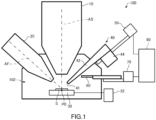
- FIG. 1 shows the configuration of the FIB system, 100.
- the FIB system 100 includes an SEM (scanning electron microscope) column 10, an FIB (focused ion beam) column 20, a sample stage 30, a cooling mechanism 32, a gas ejector 40 equipped with a nozzle 42, a nozzle support mechanism 50, a shield member 60, a shield member support mechanism 70, and a controller 80. Because the FIB system 100 is equipped with the SEM column 10 and the FIB column 20, the system permits milling and observation of a sample S.
- SEM scanning electron microscope
- FIB focused ion beam
- the SEM column 10 that irradiates the sample S with an electron beam operates to form and scan an electron probe.
- the SEM column 10 includes an electron gun for emitting the electron beam and an electron optical system that focuses the electron beam into the electron probe and scans it.
- the electron beam emitted from the electron gun travels along the optical axis AS of the SEM column 10 and strikes the sample S.
- the FIB system 100 can produce SEM images by scanning the sample S with the electron probe and detecting electrons emanating from the sample S with an electron detector (not shown).
- the FIB column 20 that operates to irradiate the sample S with an ion beam forms and scan the ion beam.
- the FIB column 20 includes an ion gun for emitting the ion beam and an ion optical system for focusing the ion beam and scanning the focused ion beam.
- the ion beam emanating from the ion gun travels along the optical axis AF of the FIB column 20 and strikes the sample S.
- the FIB system 100 can mill the sample S by scanning the sample S with the focused ion beam.
- the sample stage 30 mechanically supports the sample S, which in turn is disposed in a sample chamber 102.
- the sample chamber 102 is evacuated to a vacuum or subatmospheric condition by a vacuum pump (not shown).
- a vacuum pump not shown.
- milling and observation of the sample S are carried out at the intersection point P0 of the optical axes AS and AF.
- the sample stage 30 includes a drive mechanism for moving the sample S horizontally and vertically, as well as a tilt mechanism for tilting the sample S.
- the drive mechanism and tilt mechanism use drive sources such as electric motors.
- the sample stage 30 may be so configured that it can support a sample holder which can be shared between the FIB system 100 and a transmission electron microscope. That is, the sample stage 30 may support the sample S via a sample holder capable of being shared between the FIB system and the transmission electron microscope.
- the cooling mechanism 32 cools the sample stage 30, resulting in cooling of the sample S.
- the cooling mechanism 32 includes, for example, a tube through which a gas flows and a refrigerant tank for cooling the gas.
- the cooling mechanism 32 cools the sample stage 30 by passing the gas cooled with the refrigerant tank filled with liquid nitrogen, for example, through the tube in thermal communication with the sample stage 30.
- the cooling mechanism 32 may include a refrigerant tank and thermal conductive lines that thermally connect the refrigerant tank with the sample stage 30, whereby the sample stage 30 can be cooled.
- the FIB system 100 is equipped with the cooling mechanism 32 for cooling the sample stage 30 in this way, the system can be used as a cryo-FIB capable of milling the sample S while cooling it. Therefore, with the FIB system 100, biological samples in frozen state, battery materials, and so on can be milled and observed.
- the gas ejector 40 blows a gas against the sample S to deposit a film.
- the sample S is irradiated with an electron beam or an ion beam while blowing the gas against the sample S with the gas ejector 40.
- Secondary electrons emanating from the irradiated sample S decomposes the gas into the deposited film material and gas components. Consequently, the deposited film material adheres to the sample S, depositing the film.
- a gas is blown against the sample S without any beam irradiation. The gas adheres to the surface of the cooled sample S. Consequently, a film can be deposited.
- the gas ejector 40 has the nozzle 42 and a reservoir tank 44.
- a gas source is housed in the reservoir tank 44, which in turn is disposed outside the sample chamber 102.
- the nozzle 42 is a thin, elongated cylindrical member and has a blowoff port 41 at its front end. A gas is discharged from the blowoff port 41 and blown against the sample S. When the gas is blown against the sample S, the nozzle support mechanism 50 places the blowoff port 41 close to the sample S.
- the nozzle 42 is movably supported by the nozzle support mechanism 50.
- the whole gas ejector 40 including the nozzle 42 and the reservoir tank 44 is movably supported by the nozzle support mechanism 50.
- the nozzle support mechanism 50 is a single-axis actuator including drive sources (such as an electric motor and an air cylinder) and a power transfer member (such as a linear guide) interconnecting the drive sources and the nozzle 42. No restrictions are imposed on the structure of the nozzle support mechanism 50 as long as the nozzle 42 can be movably supported by the support mechanism 50.
- the shield member 60 acts to impede the flow of gas and is made of a flat plate-like member, for example. Because the shield member 60 is located between the blowoff port 41 and the sample S, the flow of gas leaking out from the nozzle 42 and going toward the sample S can be impeded. No restrictions are placed on the shape and material of the shield member 60 as long as it can impede the flow of gas.
- the shield member 60 is movably supported by the shield member support mechanism 70 that is a one-axis actuator including a motive device (such as a motor or an air cylinder) and a power transfer member (such as a linear guide) connecting together the motive device and the nozzle 42.
- a motive device such as a motor or an air cylinder
- a power transfer member such as a linear guide
- the controller 80 controls the nozzle support mechanism 50 and the shield member support mechanism 70 and includes a processor such as a CPU (central processing unit) or a DSP (digital signal processor) and memories (such as a RAM (random access memory) and a ROM (read only memory)). Programs and data permitting various kinds of control operations are stored in the memories.
- the functions of the controller 80 can be implemented by executing programs with the processor.
- the controller 80 includes an input device serving as a user interface for accepting a user's instructions.
- FIGS. 2 and 3 are schematic cross sections of the gas ejector 40 that includes the nozzle 42, the reservoir tank 44, and a valve 46.
- FIG. 2 shows a state in which the valve 46 is open.
- FIG. 3 shows a state in which the valve 46 is closed.
- a gas source 4 in liquid or solid form is accommodated in the reservoir tank 44.
- the gas source 4 include carbon compounds, tungsten compounds, and platinum compounds.
- Gas 2 produced from the gas source 4 is supplied from the reservoir tank 44 into the nozzle 42 through the valve 46.
- the valve 46 is mounted between the nozzle 42 and the reservoir tank 44.
- the gas 2 can be ejected from the nozzle 42 by opening the valve 46.
- the ejection of the gas 2 can be stopped by closing the valve 46.
- the nozzle 42 is connected to the reservoir tank 44 via the valve 46.
- the nozzle 42 is a cylindrical member that blows the gas 2 from the blowoff port 41 against the sample S.
- the use of the thin, elongated nozzle 42 makes it possible to locate the reservoir tank 44 remotely from the sample S.
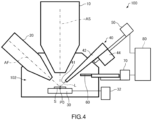
- FIGS. 4 and 5 illustrate the operation of the focused ion beam (FIB) system 100.
- the nozzle 42 can move between a deposition position shown in FIG. 4 and the retractive position of the nozzle shown in FIG. 5 .
- the shield member 60 can move between its retractive position shown in FIG. 4 and a shield position shown in FIG. 5 .
- the controller 80 varies the position of the shield member 60 according to the position of the nozzle 42.
- the controller 80 causes the shield member support mechanism 70 to move the shield member 60 from its retractive position to the shield position.
- the controller 80 causes the shield member support mechanism 70 to move the shield member 60 to its retractive position from the shield position.
- the nozzle 42 When a film is deposited using the gas ejector 40 as shown in FIG. 4 , the nozzle 42 is placed at a deposition position where the nozzle 42 can blow the gas 2 from its blowoff port 41 against the sample S. Since the nozzle 42 is located at the deposition position, the blowoff port 41 is placed close to the sample S. For example, if the nozzle 42 is placed at the deposition position, the distance between the blowoff port 41 and the surface of the sample S is on the order of tens to hundreds of micrometers.
- the shield member 60 When the nozzle 42 is placed at the deposition position, the shield member 60 is placed at its retractive position that does not lie between the blowoff port 41 and the sample S. When the shield member 60 is at its retractive position, the shield member 60 does not intersect the line segment L that connects the center of the blowoff port 41 and the intersection point P0. Therefore, if the shield member 60 is placed at its retractive position, the shield member 60 does not impede the flow of the gas 2 blown out of the blowoff port 41.
- the valve 46 is opened as shown in FIG. 2 .
- the gas 2 is blown from the blowoff port 41. Consequently, the gas 2 can be blown against the surface of the sample S and thus a film can be deposited on the surface of the sample S.
- the valve 46 is closed as shown in FIG. 3 , the supply of the gas 2 from the reservoir tank 44 to the nozzle 42 is cut off.
- the controller 80 When the nozzle 42 is retracted after a film has been deposited, the user instructs the controller 80 to retract the nozzle 42. In response, the controller 80 causes the nozzle support mechanism 50 to move the nozzle 42 linearly from the deposition position of FIG. 4 to the retractive position of the nozzle shown in FIG. 5 .
- the nozzle 42 When the nozzle 42 is in its retractive position, the nozzle 42 is sufficiently remote from the sample S.
- the distance between the blowoff port 41 and the sample S as taken when the nozzle 42 is in its retractive position as shown in FIG. 5 is greater than the distance between the blowoff port 41 and the sample S as taken when the nozzle 42 is in the deposition position as shown in FIG. 4 .
- the controller 80 After instructing the nozzle support mechanism 50 to move the nozzle 42 from the deposition position to the retractive position of the nozzle, the controller 80 causes the shield member support mechanism 70 to move the shield member 60 from its retractive position of FIG. 4 to the shield position of FIG. 5 .
- the shield position is located between the blowoff port 41 and the sample S supported on the sample stage 30.
- the shield member 60 intersects the line segment L that connects the center of the blowoff port 41 and the intersection point P0.
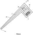
- FIG. 6 is a schematic cross-sectional view of the gas ejector 40 when the valve 46 is closed after blowing the gas 2 against the sample S.
- the nozzle 42 is thin and long and so if the valve 46 is closed, the gas 2 will remain in the nozzle 42. If the remaining gas 2 leaks out of the nozzle 42 and reaches the surface of the sample S, a film will be deposited unintentionally on the surface of the sample S.
- a film is deposited without electron or ion beam irradiation. Therefore, the gas 2 leaking from the nozzle 42 produces a film deposited on the surface of the sample S to such a large thickness that observation and analysis using an electron microscope may be adversely affected.
- a thick film may be deposited on the surface of the sample S depending on the species of the gas 2.
- the shield member 60 moves to the shield position as described above. Therefore, the shield member 60 can impede the flow of the gas 2 going toward the sample S after leaking from the nozzle 42.
- the degree of vacuum in the sample chamber 102 is in the molecular flow region on the order of 10 -5 to 10 -6 Pa. In this region, gas molecules travel nearly straight. Therefore, gas molecules colliding with the shield member 60 after being ejected from the blowoff port 41 are scattered within the sample chamber 102 without going around the shield member 60. Accordingly, the placement of the shield member 60 between the blowoff port 41 and the sample S almost fully eliminates gas molecules going from the blowoff port 41 toward the sample S. Therefore, there are very few gas molecules which collide with the wall of the sample chamber 102 and reach the sample S after colliding with the shield member 60. Therefore, in the FIB system 100, the amount of gas reaching the sample S after leaking from the nozzle 42 can be reduced. Consequently, it can be prevented that a film is deposited on the surface of the sample S to such a thickness that observation and analysis using an electron microscope are adversely affected.
- the user instructs the controller 80 to insert the nozzle 42.
- the controller 80 causes the shield member support mechanism 70 to move the shield member 60 from the shield position ( FIG. 5 ) to the retractive position ( FIG. 4 ) of the shield member.
- the controller 80 causes the nozzle support mechanism 50 to move the nozzle 42 from the retractive position ( FIG. 5 ) of the nozzle to the deposition position ( FIG. 4 ). Consequently, a film can be deposited.
- the focused ion beam (FIB) system 100 includes: the FIB column 20 through which the ion beam is directed at the sample S; the nozzle 42 for blowing the gas 2 from the blowoff port 41 against the sample S to deposit a film; the sample stage 30 providing mechanical support of the sample S; the shield member 60 for impeding the flow of the gas 2, the shield member 60 being movable to the shield position located between the blowoff port 41 and the sample S supported on the stage 30, the shield member 60 being also movable to its retractive position not located between the blowoff port 41 and the sample S on the sample stage 30; and the shield member support mechanism 70 by which the shield member 60 is supported such that it can move between the shield position and the retractive position of the shield member.
- the shield member 60 can be disposed between the blowoff port 41 and the sample S. This can reduce the amount of gas leaking from the nozzle 42 and reaching the sample S. Consequently, in the FIB system 100, it can be prevented unintentionally that a film is deposited on the surface of the sample S so thickly that observation and analysis using an electron microscope are adversely affected.
- the FIB system 100 includes: the nozzle support mechanism 50 for supporting the nozzle 42 so that it can move between the deposition position at which the gas 2 is blown against the sample S from the blowoff port 41 and the retractive position of the nozzle different from the deposition position; and the controller 80 for controlling the nozzle support mechanism 50 and the shield member support mechanism 70.
- the controller 80 causes the shield member support mechanism 70 to move the shield member 60 from its retractive position to the shield position. Therefore, in the FIB system 100, when the nozzle 42 is moved from the deposition position to the retractive position of the nozzle, the shield member 60 automatically moves from its retractive position to the shield position. Consequently, with the FIB system 100, it can be prevented that a film is deposited thickly on the surface of the sample S without user's consciousness.
- the controller 80 causes the shield member support mechanism 70 to move the shield member 60 from the shield position to the retractive position of the shield member. Therefore, in the FIB system 100, if the nozzle 42 is moved from its retractive position to the deposition position, the shield member 60 is automatically moved from the shield position to the retractive position of the shield member. Consequently, with the FIB system 100, it can be prevented unintentionally that a film is deposited thickly on the surface of the sample S.
- the FIB system 100 includes the cooling mechanism 32 for cooling the sample stage 30.
- the shield member 60 can be placed between the blowoff port 41 and the sample S. Therefore, if the FIB system 100 is a cryo-FIB system which mills the sample S while cooling it, it can be prevented without user's consciousness that a film is deposited thickly on the surface of the sample S.
- the FIB system 100 includes the reservoir tank 44 that contains the gas source 4 producing the gas 2 and the valve 46 mounted between the nozzle 42 and the reservoir tank 44.
- the gas 2 is supplied from the reservoir tank 44 into the nozzle 42 by opening the valve 46.
- the shield member 60 is positioned between the blowoff port 41 and the sample S. Therefore, when the valve 46 is closed, the amount of gas reaching the sample S after leaking from the nozzle 42 can be reduced.
- the controller 80 varies the position of the shield member 60 by controlling the shield member support mechanism 70 according to the position of the nozzle 42.
- the processing of the controller 80 is not restricted to this operation.
- the controller 80 may vary the position of the shield member 60 by controlling the shield member support mechanism 70 in response to an instruction by a user. That is, if an instruction for moving the shield member 60 to the shield position is accepted from a user, the controller 80 causes the shield member support mechanism 70 to move the shield member 60 to the shield position. Also, if an instruction for moving the shield member 60 to its retractive position is accepted from a user, the controller 80 causes the shield member support mechanism 70 to move the shield member 60 to its retractive position.
- the controller 80 controls the shield member support mechanism 70 to vary the position of the shield member 60.
- a user may vary the position of the shield member 60 by manually manipulating the shield member support mechanism 70.
- the support mechanism 70 has no driver device, for example. The user may manually move the shield member 60 via a mechanical element such as a shaft connected to the shield member 60.
- the controller 80 controls the nozzle support mechanism 50 to vary the position of the nozzle 42.
- the user may vary the position of the nozzle 42 by manually manipulating the nozzle support mechanism 50.
- the nozzle support mechanism 50 has no driver device, for example.
- the user may manually move the nozzle 42 via a mechanical element such as a shaft connected to the nozzle 42.
- FIG. 7 shows a modification of the FIB system 100, the modification including a detector 90 for detecting electrons emitted from the sample S in response to irradiation of the sample S with an electron beam.
- the shield member 60 is connected to the detector 90.
- the detector 90 is a backscattered electron detector for detecting backscattered electrons emanating from the sample S.
- the SEM column 10 scans the sample S with an electron probe. Backscattered electrons emanating from the sample S are detected by the detector 90. As a result, a backscattered electron image can be obtained.
- the shield member 60 and the detector 90 are movably supported by the shield member support mechanism 70. That is, the shield member support mechanism 70 also acts as a detector support mechanism movably supporting the detector 90 and so the parts count can be reduced.
- the shield member support mechanism 70 brings the detector 90 just under the SEM column 10 capable of detecting backscattered electrons.
- the shield member support mechanism 70 moves the detector 90 to its retractive position shown in FIG. 7 , the retractive position being set remotely from the sample S.
- the detector 90 to which the shield member 60 is connected is not restricted to a backscattered electron detector. Rather, any detector that detects signals emanating from the sample S can be used.
- the detector 90 may be an X-ray detector for detecting characteristic X-rays emitted from the sample S or an EBSD detector for producing EBSD (electron backscatter diffraction).
- the member to which the shield member 60 is connected is not restricted to a detector but rather any other member disposed in the sample chamber 102 may also be available.
- the shield member 60 may be connected to a manipulator for picking up a section cut out of the sample S.
- the shield member 60 and the manipulator may be movably supported by the shield member support mechanism 70.
- the controller 80 operates the shield member support mechanism 70 in response to the operation of the nozzle support mechanism 50.
- the shield member support mechanism 70 may be so configured that the operation of the shield member support mechanism 70 mechanically links with the operation of the nozzle support mechanism 50. That is, when the nozzle support mechanism 50 moves the nozzle 42 from the deposition position to the retractive position of the nozzle, the shield member support mechanism 70 may move the shield member 60 from its retractive position to the shield position in a mechanical interlocking manner with the operation of the nozzle support mechanism 50.
- the shield member support mechanism 70 may move the shield member 60 from the shield position to the retractive position of the shield member in a mechanical interlocking manner with the operation of the nozzle support mechanism 50.
- the shield member support mechanism 70 moves the shield member 60 between the shield position and the retractive position of the shield member in a mechanical interlocking manner with the movement of the nozzle 42. Consequently, it can be prevented without user's consciousness that a film is deposited thickly on the surface of the sample S.
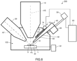
- FIGS. 8 and 9 show the configuration of the FIB system, 200, associated with the second embodiment. Note that FIGS. 8 and 9 correspond to FIGS. 4 and 5 , respectively.
- Those members of the FIB system 200 which are similar in function to their respective counterparts of the FIB system 100 associated with the first embodiment are hereinafter indicated by the same reference numerals as in the foregoing figures and a detailed description thereof is omitted.
- the shield member 60 is a cover in the form of a flat plate that plugs the blowoff port 41 of the nozzle 42.
- the shield member support mechanism 70 includes a support member 72 providing mechanical support of the shield member 60, a shaft member 73 by which the shield member 60 is rotatably connected to the support member 72, and a driver device 74 for rotating the shield member 60 around the shaft member 73.
- the shield member 60 can be moved between a shield position ( FIG. 9 ) and a retractive position ( FIG. 8 ) of the shield member by rotating the shield member 60 around the shaft member 73 by means of the driver device 74.
- the cover made of the shield member 60 plugging the blowoff port 41 can be opened.
- the blowoff port 41 can be covered by placing the shield member 60 into the shield position as shown in FIG. 9 .
- the nozzle 42 is supported by the nozzle support mechanism 50.
- the shield member 60 is supported by the shield member support mechanism 70. Since the nozzle 42 and the shield member 60 are supported by separate members in this way, if the nozzle 42 is moved into the deposition position, the shield member 60 can be placed in its retractive position remote from the sample S. Accordingly, in the FIB system 200, effective use can be made of the space in the vicinity of the sample S.
- FIB focused ion beam
- the nozzle 42 is placed in the deposition position where the gas 2 is blown from the blowoff port 41 against the sample S.
- the valve 46 is opened as shown in FIG. 2 .
- a film can be deposited on the surface of the sample S.
- the shield member 60 is in its retractive position and so the shield member 60 is switched from closed state (i.e., plugging up the blowoff port 41) to open state. Under this condition, the flow of the gas 2 blown out from the shield member 60 through its blowoff port 41 is not impeded.
- the controller 80 causes the nozzle support mechanism 50 to move the nozzle 42 from the deposition position to the retractive position of the nozzle as shown in FIG. 9 . Then, the controller 80 causes the shield member support mechanism 70 to move the shield member 60 from its retractive position to the shield position. Consequently, the blowoff port 41 can be covered by the shield member 60. This can impede the flow of the gas 2 which goes toward the sample S after leaking out from the nozzle 42.
- the shield member 60 can be positioned between the blowoff port 41 and the sample S in the same manner as in the foregoing FIB system 100. Therefore, with the FIB system 200, it can be prevented unintentionally that a film is deposited on the surface of the sample S so thickly that observation and analysis using an electron microscope are adversely affected.
- the controller 80 operates the shield member support mechanism 70 in response to the operation of the nozzle support mechanism 50.
- the shield member support mechanism 70 may be so configured as to operate in a mechanical interlocking manner with the operation of the nozzle support mechanism 50 in the same manner as in the fourth modification of the first embodiment.
- the shield member support mechanism 70 may include a biasing member such as a spring for maintaining the shield member 60 at the shield position.
- a biasing member such as a spring for maintaining the shield member 60 at the shield position.
- the first and second modifications of the first embodiment are also applicable to the focused ion beam system 200 associated with the second embodiment.
- FIGS. 10 and 11 show the configuration of the FIB system, 300, associated with the third embodiment.
- FIGS. 10 and 11 correspond to FIGS. 4 and 5 , respectively.
- Those members of the FIB system 300 which are similar in function to their respective counterparts of the FIB system 100 associated with the first embodiment are hereinafter indicated by the same reference numerals as in the foregoing figures and a detailed description thereof is omitted.
- the amount of the gas 2 reaching the sample S after leaking from the nozzle 42 is reduced by placing the shield member 60 between the blowoff port 41 and the sample S as shown in FIG. 5 .
- the amount of the gas 2 reaching the sample S after leaking from the nozzle 42 is reduced by moving the nozzle 42 so that the blowoff port 41 faces away from the sample S.
- the nozzle 42 has a first portion 42a and a second portion 42b which are connected together.
- the second portion 42b has the blowoff port 41 at its front end.
- the first portion 42a and the second portion 42b have central axes A1 and A2, respectively, which are tilted relative to each other. That is, the nozzle 42 is bent at the joint between the first portion 42a and the second portion 42b.
- the second portion 42b is shorter in length than the first portion 42a.
- the nozzle support mechanism 50 moves the nozzle 42 rectilinearly along the central axis A1 relative to which the central axis A2 of the second portion 42b is tilted. This causes the nozzle 42 to face away from the blowoff port 41. Therefore, it is possible to effect a switch between the operable state in which a film can be deposited and the retracted state.
- the blowoff port 41 faces towards the sample S along the central axis A2. Where the surface of the sample S and the central axis A2 intersect with each other, the blowoff port 41 faces towards the sample S. In the operable state, the central axis A2 intersects the surface of the sample S, and the gas 2 blown out from the blowoff port 41 flows toward the sample S. Consequently, a film can be deposited on the surface of the sample S.
- the blowoff port 41 faces away from the sample S and the central axis A2 of the second portion 42b does not intersect the surface of the sample S.
- gas molecules travel nearly straight and so, in the retracted state, the gas 2 blown out of the blowoff port 41 flows in directions not directed toward the sample S. Therefore, in the retractive state, the amount of the gas 2 reaching the sample S after leaking from the nozzle 42 can be reduced as compared to in the operable state.
- the nozzle 42 is placed at the deposition position as shown in FIG. 10 .
- the blowoff port 41 of the nozzle 42 faces towards the sample S and thus a film can be deposited.
- valve 46 is opened as shown in FIG. 2 .
- the gas 2 is blown out of the blowoff port 41. Consequently, the gas 2 can be blown against the surface of the sample S. Thus, a film can be deposited on the surface of the sample S.
- the controller 80 Upon accepting an instruction to retract the nozzle 42, the controller 80 causes the nozzle support mechanism 50 to move the nozzle 42 from the deposition position to the retractive position of the nozzle, at which the blowoff port 41 of the nozzle 42 faces away from the sample S as shown in FIG. 11 , resulting in a retracted state. In consequence, the amount of the gas 2 reaching the sample S after leaking from the nozzle 42 can be reduced.
- the controller 80 Upon accepting an instruction to insert the nozzle 42, the controller 80 causes the nozzle support mechanism 50 to move the nozzle 42 from its retractive position to the deposition position, whereby the blowoff port 41 of the nozzle 42 faces towards the sample S as shown in FIG. 10 and thus a film can be deposited.
- the focused ion beam (FIB) system 300 includes the nozzle support mechanism 50 acting as a switching mechanism for effecting a switch between the operable state in which the blowoff port 41 of the nozzle 42 faces towards the sample S and thus a film can be deposited and the retracted state in which the blowoff port 41 faces away from the sample S. Therefore, in the FIB system 300, when the nozzle 42 is not used, the retracted state in which the blowoff port 41 faces away from the sample S can be accomplished. Consequently, with the FIB system 300, it can be prevented unintentionally that a film is deposited on the surface of the sample S so thickly that observation and analysis using an electron microscope are adversely affected, in the same manner as for the FIB system 100.
- the nozzle support mechanism 50 acting as a switching mechanism moves the nozzle 42, whereby enabling to effect a switch between the operable state in which a film can be deposited and the retracted state. Accordingly, the FIB system 300 does not need to use the shield member 60 unlike the FIB system 100 and so the parts count can be reduced.
- the controller 80 controls the nozzle support mechanism 50 to vary the position of the nozzle 42.
- the user may vary the position of the nozzle 42 by manually manipulating the nozzle support mechanism 50.
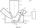
- FIGS. 12 and 13 show the configuration of the FIB system, 400, associated with the fourth embodiment.
- FIGS. 12 and 13 correspond to FIGS. 4 and 5 , respectively.
- Those members of the FIB system 400 which are similar in function to their respective counterparts of the FIB systems 100 and 300 associated with the first and third embodiments are indicated by the same reference numerals as in the foregoing figures and a detailed description thereof is omitted.
- a switch is effected between the operable state in which a film can be deposited and the retracted state by moving the nozzle 42 by means of the nozzle support mechanism 50 acting as a switching mechanism.
- the nozzle support mechanism 50 acting as a switching mechanism rotates the nozzle 42 to switch between the operable state shown in FIG. 12 and the retracted state shown in FIG. 13 .
- the nozzle support mechanism 50 rotationally moves the nozzle 42 and includes, for example, a shaft member by which the nozzle 42 is rotatably supported and a driver device such as an electric motor.
- the nozzle 42 is rotated around the shaft member by power from the driver device.
- the nozzle 42 is tilted by rotationally moving it and thus the blowoff port 41 can be varied in sense. Consequently, a switch can be effected between the operable state in which the blowoff port 41 faces towards the sample S and thus a film can be deposited and the retracted state in which the port 41 faces away from the sample S.
- the nozzle 42 is in the form a straight cylinder but the nozzle 42 may be bent as shown in FIGS. 10 and 11 .
- the operation of the focused ion beam system 400 is similar to the operation of the above-described focused ion beam system 300 except that the nozzle support mechanism 50 rotates the nozzle 42 and so a description thereof is omitted.
- the nozzle support mechanism 50 acting as the switching mechanism moves the nozzle 42 and thus a switch can be effected between the operable state in which a film can be deposited and the retracted state. Accordingly, with the FIB system 400, it can be prevented unintentionally that a film is deposited on the surface of the sample S thickly, in the same manner as for the FIB system 100.
- Moving the nozzle 42 involves moving the nozzle 42 rectilinearly as shown in FIGS. 10 and 11 and rotationally moving the nozzle 42 as shown in FIGS. 12 and 13 .
- the nozzle support mechanism 50 rotates the nozzle 42 and the reservoir tank 44 together.
- the nozzle support mechanism 50 may rotate only the nozzle 42 in a manner not illustrated. This can be implemented, for example, by connecting together the reservoir tank 44 and the nozzle 42 via a deformable member such as a resinous tube or a metal bellows.
- the nozzle support mechanism 50 may move the nozzle 42 by utilizing a combination of the rotational movement of the nozzle 42 as illustrated in FIGS. 12 and 13 and the linear movement of the nozzle 42 as illustrated in FIGS. 4 and 5 .
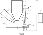
- FIGS. 14 and 15 show the configuration of the FIB system, 500, associated with the fifth embodiment.
- FIGS. 14 and 15 correspond to FIGS. 4 and 5 , respectively.
- Those members of the FIB system 500 which are similar in function to their respective counterparts of the FIB systems 100, 300, and 400 associated with the first, third, and fourth embodiments, respectively, are indicated by the same reference numerals as in the foregoing figures and a detailed description thereof is omitted.
- a switch is effected between the operable state in which a film can be deposited and the retracted state by moving the nozzle 42.
- the sample S is moved to switch between the operable state of FIG. 15 and the retracted state of FIG. 14 .
- the nozzle 42 is fixed and located such that the blowoff port 41 faces away from the intersection point P0.
- the nozzle 42 is so located that the blowoff port 41 faces downward, and the nozzle 42 is positioned remotely from the intersection point P0.
- the sample stage 30 moves the sample S between a milling position being the intersection point P0 shown in FIG. 14 and the deposition position at which the surface of the sample S intersects with the central axis A0 of the nozzle 42 as shown in FIG. 15 .
- the sample stage 30 moves the sample S horizontally.
- the milling position where the sample S is milled and observed is different from the deposition position where a film is deposited on the sample S.
- the nozzle 42 is placed into the retracted state where the blowoff port 41 faces away from the sample S. Therefore, the amount of the gas 2 hitting the sample S after leaking from the nozzle 42 can be reduced. If the sample S is placed at the deposition position as shown in FIG. 15 , the nozzle 42 is placed into the operable state in which the blowoff port 41 faces towards the sample S. Under this condition, therefore, a film can be deposited on the surface of the sample S. In this way, the sample stage 30 acts as a switching mechanism for effecting a switch between the operable state and the retracted state.
- the sample S is placed at the deposition position as shown in FIG. 15 .
- the blowoff port 41 of the nozzle 42 faces towards the sample S and thus a film can be deposited.
- the valve 46 is opened as shown in FIG. 2 , so that the gas 2 is blown out from the blowoff port 41. Consequently, the gas 2 can be blown against the surface of the sample S. Because the sample S is being cooled by the sample stage 30, a film can be deposited on the surface of the sample S by the blowing of the gas 2 without irradiating the sample with an electron beam or an ion beam.
- the user instructs the controller 80 to move the sample S into the milling position.
- the controller 80 causes the sample stage 30 to move the sample S from the deposition position of FIG. 15 to the milling position of FIG. 14 . This places the sample S into the intersection point P0, whereby milling and observation of the sample S are possible.
- placing the sample S into the milling position causes the blowoff port 41 of the nozzle 42 to face away from the sample S.
- the amount of the gas 2 reaching the sample S after leaking from the nozzle 42 can be reduced because the blowoff port 41 does not face towards the sample S. Accordingly, if neither milling nor observation is made, for example, the amount of the gas 2 reaching the sample S after leaking from the nozzle 42 can be reduced by placing the sample S into the milling position.
- the user instructs the controller 80 to move the sample S into the deposition position.
- the controller 80 causes the sample stage 30 to move the sample S from the milling position of FIG. 14 to the deposition position of FIG. 15 , whereby the blowoff port 41 of the nozzle 42 faces towards the sample S. In consequence, a film can be deposited on the surface of the sample S.
- the sample stage 30 acting as a switching mechanism moves the sample S, thus effecting a switch between the operable state in which a film can be deposited and the retracted state. Consequently, with the FIB system 500, it can be prevented unintentionally that a film is deposited thickly on the surface of the sample S in the same way as for the FIB system 100.
- FIB focused ion beam
- the nozzle 42 is fixed and so a mechanism for moving the nozzle 42 is dispensed with unlike the FIB system 100. Hence, the parts count can be reduced.
- the focused ion beam system 100 is equipped with both SEM column 10 and FIB column 20.
- the FIB system 100 does not need to have the SEM column 10.
- the FIB systems associated with the second through fifth embodiments may not need to have the SEM column 10.
- the present invention is not restricted to the foregoing embodiments but rather implemented in variously modified forms.
- the present invention embraces configurations (e.g., configurations identical in function and method) which are substantially identical to the configurations described in the above embodiments.
- the invention embraces configurations which are similar to the configurations described in the above embodiments except that their nonessential portions have been replaced.
- the invention embraces configurations which are similar to the configurations described in any one of the above embodiments except that a well-known technique is added.
Landscapes
- Chemical & Material Sciences (AREA)
- Engineering & Computer Science (AREA)
- Analytical Chemistry (AREA)
- Materials Engineering (AREA)
- Mechanical Engineering (AREA)
- Metallurgy (AREA)
- Organic Chemistry (AREA)
- Chemical Kinetics & Catalysis (AREA)
- Physics & Mathematics (AREA)
- Plasma & Fusion (AREA)
- Sampling And Sample Adjustment (AREA)
- Drying Of Semiconductors (AREA)
- Chemical Vapour Deposition (AREA)
Abstract
Description
- The present invention relates to a focused ion beam (FIB) system.
- In a focused ion beam (FIB) system, a sample can be milled by scanning its surface with a focused ion beam. Furthermore, in this FIB system, a film can be deposited on the surface of the sample by irradiating the sample with an electron beam or an ion beam while blowing a gas compound against and around the sample surface. With a cryo-FIB system in which a cooled sample is milled, a film can be deposited on the surface of the sample only by blowing a gas compound against the sample without any beam irradiation.
- In Patent document 1, there is disclosed a focused ion beam system equipped with a gas gun for blowing a gas compound against a sample. The gas gun includes a gas tank containing a gas source as well as a gas nozzle. When a film is deposited, the gas nozzle is moved by an air cylinder from its retracted position so as to approach a height hundreds of micrometers away from the milled point on the sample. A gas seal plug is mounted in the gas tank. Gas can be blown against the sample by opening the gas seal plug.
- Patent document 1:
JP-A-2007-134520 - With the above-described gas gun, if the gas tank is closed with the gas seal plug, gas remains inside the gas nozzle and leaks out through the gas nozzle. Then, the leaking gas reaches the surface of the sample. As a result, a film may be unintentionally deposited so thickly that observation and analysis using an electron microscope are adversely affected.
- One aspect of the focused ion beam system associated with the present invention is adapted to mill a sample by irradiating it with an ion beam and comprises:
- an ion beam column through which the ion beam is directed at the sample;
- a nozzle having a blowoff port for blowing a gas against the sample to deposit a film;
- a sample stage providing mechanical support of the sample;
- a shield member for impeding the flow of the gas, the shield member being movable to a shield position that is located between the blowoff port and the sample supported on the sample stage, the shield member being also movable to a retractive position not located between the blowoff port and the sample supported on the sample stage; and
- a shield member support mechanism for supporting the shield member so that the shield member can move between the shield position and the retractive position of the shield member.
- In this FIB system, when the nozzle is not in use, the shield member can be placed between the blowoff port and the sample. This can reduce the amount of gas reaching the sample after leaking from the nozzle. Consequently, it can be prevented that a film is deposited on the surface of the sample so thickly that observation and analysis using an electron microscope are adversely affected.
- Another aspect of the focused ion beam system associated with the present invention is adapted to mill a sample by irradiating it with an ion beam and comprises:
- an ion beam column through which the ion beam is directed at the sample;
- a nozzle having a blowoff port for blowing a gas against the sample to deposit a film;
- a sample stage providing mechanical support of the sample; and
- a switching mechanism for effecting a switch between an operable state in which the blowoff port faces towards the sample and a film can be deposited and a retracted state in which the blowoff port faces away from the sample.
- When the nozzle of this FIB system is not used, the FIB system can be placed in the retracted state in which the blowoff port faces away from the sample. Therefore, with this FIB system, the amount of the gas leaking out from the nozzle and reaching the sample can be reduced. Thus, it can be prevented that a film is deposited on the surface of the sample so thickly that observation and analysis using an electron microscope are adversely affected.
-
-
FIG. 1 is a schematic view, partly in block form, showing the configuration of a focused ion beam (FIB) system associated with one embodiment of the present invention. -
FIGS. 2 and3 are schematic cross-sectional views of a gas ejector, illustrating different modes of operation. -
FIGS. 4 and5 are schematic views similar toFIG. 1 , but illustrating operations of the FIB system. -
FIG. 6 is a schematic cross-sectional view similar toFIG. 3 , but in which the valve is closed. -
FIG. 7 is a schematic view showing a modification of the FIB system ofFIG. 1 . -
FIGS. 8 and9 are schematic views, partly in block form, showing the configuration of an FIB system associated with a second embodiment. -
FIGS. 10 and11 are schematic views, partly in block form, showing the configuration of an FIB system associated with a third embodiment. -
FIGS. 12 and13 are schematic views, partly in block form, showing the configuration of an FIB system associated with a fourth embodiment. -
FIGS. 14 and15 are schematic views, partly in block form, showing the configuration of an FIB system associated with a fifth embodiment. - The preferred embodiments of the present invention are hereinafter described in detail with reference to the drawings. It is to be understood that the embodiments provided below do not unduly restrict the scope and content of the present invention delineated by the appended claims and that not all the configurations described below are essential constituent components of the invention.
- A focused ion beam (FIB) system associated with a first embodiment is first described by referring to
FIG. 1 , which shows the configuration of the FIB system, 100. As shown, the FIBsystem 100 includes an SEM (scanning electron microscope)column 10, an FIB (focused ion beam)column 20, asample stage 30, acooling mechanism 32, agas ejector 40 equipped with anozzle 42, anozzle support mechanism 50, ashield member 60, a shieldmember support mechanism 70, and acontroller 80. Because the FIBsystem 100 is equipped with theSEM column 10 and theFIB column 20, the system permits milling and observation of a sample S. - The
SEM column 10 that irradiates the sample S with an electron beam operates to form and scan an electron probe. TheSEM column 10 includes an electron gun for emitting the electron beam and an electron optical system that focuses the electron beam into the electron probe and scans it. The electron beam emitted from the electron gun travels along the optical axis AS of theSEM column 10 and strikes the sample S. - The
FIB system 100 can produce SEM images by scanning the sample S with the electron probe and detecting electrons emanating from the sample S with an electron detector (not shown). - The FIB
column 20 that operates to irradiate the sample S with an ion beam forms and scan the ion beam. The FIBcolumn 20 includes an ion gun for emitting the ion beam and an ion optical system for focusing the ion beam and scanning the focused ion beam. The ion beam emanating from the ion gun travels along the optical axis AF of theFIB column 20 and strikes the sample S. The FIBsystem 100 can mill the sample S by scanning the sample S with the focused ion beam. - The
sample stage 30 mechanically supports the sample S, which in turn is disposed in asample chamber 102. Thesample chamber 102 is evacuated to a vacuum or subatmospheric condition by a vacuum pump (not shown). In theFIB system 100, milling and observation of the sample S are carried out at the intersection point P0 of the optical axes AS and AF. - The
sample stage 30 includes a drive mechanism for moving the sample S horizontally and vertically, as well as a tilt mechanism for tilting the sample S. For these purposes, the drive mechanism and tilt mechanism use drive sources such as electric motors. Thesample stage 30 may be so configured that it can support a sample holder which can be shared between theFIB system 100 and a transmission electron microscope. That is, thesample stage 30 may support the sample S via a sample holder capable of being shared between the FIB system and the transmission electron microscope. - The
cooling mechanism 32 cools thesample stage 30, resulting in cooling of the sample S. Thecooling mechanism 32 includes, for example, a tube through which a gas flows and a refrigerant tank for cooling the gas. Thecooling mechanism 32 cools thesample stage 30 by passing the gas cooled with the refrigerant tank filled with liquid nitrogen, for example, through the tube in thermal communication with thesample stage 30. In addition, thecooling mechanism 32 may include a refrigerant tank and thermal conductive lines that thermally connect the refrigerant tank with thesample stage 30, whereby thesample stage 30 can be cooled. - Because the
FIB system 100 is equipped with thecooling mechanism 32 for cooling thesample stage 30 in this way, the system can be used as a cryo-FIB capable of milling the sample S while cooling it. Therefore, with theFIB system 100, biological samples in frozen state, battery materials, and so on can be milled and observed. - The
gas ejector 40 blows a gas against the sample S to deposit a film. Where a film is deposited on the sample S at room temperature, the sample S is irradiated with an electron beam or an ion beam while blowing the gas against the sample S with thegas ejector 40. Secondary electrons emanating from the irradiated sample S decomposes the gas into the deposited film material and gas components. Consequently, the deposited film material adheres to the sample S, depositing the film. Where a film is deposited on the sample S that is being cooled, a gas is blown against the sample S without any beam irradiation. The gas adheres to the surface of the cooled sample S. Consequently, a film can be deposited. - The
gas ejector 40 has thenozzle 42 and areservoir tank 44. A gas source is housed in thereservoir tank 44, which in turn is disposed outside thesample chamber 102. Thenozzle 42 is a thin, elongated cylindrical member and has ablowoff port 41 at its front end. A gas is discharged from theblowoff port 41 and blown against the sample S. When the gas is blown against the sample S, thenozzle support mechanism 50 places theblowoff port 41 close to the sample S. - The
nozzle 42 is movably supported by thenozzle support mechanism 50. Thewhole gas ejector 40 including thenozzle 42 and thereservoir tank 44 is movably supported by thenozzle support mechanism 50. Alternatively, only thenozzle 42 may be movably supported by thenozzle support mechanism 50. For example, thenozzle support mechanism 50 is a single-axis actuator including drive sources (such as an electric motor and an air cylinder) and a power transfer member (such as a linear guide) interconnecting the drive sources and thenozzle 42. No restrictions are imposed on the structure of thenozzle support mechanism 50 as long as thenozzle 42 can be movably supported by thesupport mechanism 50. - The
shield member 60 acts to impede the flow of gas and is made of a flat plate-like member, for example. Because theshield member 60 is located between theblowoff port 41 and the sample S, the flow of gas leaking out from thenozzle 42 and going toward the sample S can be impeded. No restrictions are placed on the shape and material of theshield member 60 as long as it can impede the flow of gas. - The
shield member 60 is movably supported by the shieldmember support mechanism 70 that is a one-axis actuator including a motive device (such as a motor or an air cylinder) and a power transfer member (such as a linear guide) connecting together the motive device and thenozzle 42. No restrictions are imposed on the structure of the shieldmember support mechanism 70 as long as theshield member 60 can be movably supported by thesupport mechanism 70. - The
controller 80 controls thenozzle support mechanism 50 and the shieldmember support mechanism 70 and includes a processor such as a CPU (central processing unit) or a DSP (digital signal processor) and memories (such as a RAM (random access memory) and a ROM (read only memory)). Programs and data permitting various kinds of control operations are stored in the memories. The functions of thecontroller 80 can be implemented by executing programs with the processor. Thecontroller 80 includes an input device serving as a user interface for accepting a user's instructions. -
FIGS. 2 and3 are schematic cross sections of thegas ejector 40 that includes thenozzle 42, thereservoir tank 44, and avalve 46.FIG. 2 shows a state in which thevalve 46 is open.FIG. 3 shows a state in which thevalve 46 is closed. - A
gas source 4 in liquid or solid form is accommodated in thereservoir tank 44. Examples of thegas source 4 include carbon compounds, tungsten compounds, and platinum compounds.Gas 2 produced from thegas source 4 is supplied from thereservoir tank 44 into thenozzle 42 through thevalve 46. - The
valve 46 is mounted between thenozzle 42 and thereservoir tank 44. Thegas 2 can be ejected from thenozzle 42 by opening thevalve 46. The ejection of thegas 2 can be stopped by closing thevalve 46. - The
nozzle 42 is connected to thereservoir tank 44 via thevalve 46. Thenozzle 42 is a cylindrical member that blows thegas 2 from theblowoff port 41 against the sample S. In theFIB system 100, the use of the thin,elongated nozzle 42 makes it possible to locate thereservoir tank 44 remotely from the sample S. -
FIGS. 4 and5 illustrate the operation of the focused ion beam (FIB)system 100. Thenozzle 42 can move between a deposition position shown inFIG. 4 and the retractive position of the nozzle shown inFIG. 5 . Theshield member 60 can move between its retractive position shown inFIG. 4 and a shield position shown inFIG. 5 . - The
controller 80 varies the position of theshield member 60 according to the position of thenozzle 42. In particular, when instructing thenozzle support mechanism 50 to move thenozzle 42 from the deposition position to the retractive position of the nozzle, thecontroller 80 causes the shieldmember support mechanism 70 to move theshield member 60 from its retractive position to the shield position. When instructing thenozzle support mechanism 50 to move thenozzle 42 from its retractive position to the deposition position, thecontroller 80 causes the shieldmember support mechanism 70 to move theshield member 60 to its retractive position from the shield position. - Therefore, in the
FIB system 100, if thenozzle 42 is moved from the deposition position to the retractive position of the nozzle, theshield member 60 is automatically moved from its retractive position to the shield position. Furthermore, in theFIB system 100, if thenozzle 42 is moved from its retractive position to the deposition position, theshield member 60 is automatically moved from the shield position to the retractive position of the shield member. The operation of theFIB system 100 is hereinafter described in further detail. - When a film is deposited using the
gas ejector 40 as shown inFIG. 4 , thenozzle 42 is placed at a deposition position where thenozzle 42 can blow thegas 2 from itsblowoff port 41 against the sample S. Since thenozzle 42 is located at the deposition position, theblowoff port 41 is placed close to the sample S. For example, if thenozzle 42 is placed at the deposition position, the distance between theblowoff port 41 and the surface of the sample S is on the order of tens to hundreds of micrometers. - When the
nozzle 42 is placed at the deposition position, theshield member 60 is placed at its retractive position that does not lie between theblowoff port 41 and the sample S. When theshield member 60 is at its retractive position, theshield member 60 does not intersect the line segment L that connects the center of theblowoff port 41 and the intersection point P0. Therefore, if theshield member 60 is placed at its retractive position, theshield member 60 does not impede the flow of thegas 2 blown out of theblowoff port 41. - Under the condition where the
nozzle 42 is at the deposition position, thevalve 46 is opened as shown inFIG. 2 . As a result, thegas 2 is blown from theblowoff port 41. Consequently, thegas 2 can be blown against the surface of the sample S and thus a film can be deposited on the surface of the sample S. When thevalve 46 is closed as shown inFIG. 3 , the supply of thegas 2 from thereservoir tank 44 to thenozzle 42 is cut off. - When the
nozzle 42 is retracted after a film has been deposited, the user instructs thecontroller 80 to retract thenozzle 42. In response, thecontroller 80 causes thenozzle support mechanism 50 to move thenozzle 42 linearly from the deposition position ofFIG. 4 to the retractive position of the nozzle shown inFIG. 5 . - When the
nozzle 42 is in its retractive position, thenozzle 42 is sufficiently remote from the sample S. The distance between theblowoff port 41 and the sample S as taken when thenozzle 42 is in its retractive position as shown inFIG. 5 is greater than the distance between theblowoff port 41 and the sample S as taken when thenozzle 42 is in the deposition position as shown inFIG. 4 . By bringing thenozzle 42 into its retractive position, effective use of space around the sample S can be made. - After instructing the
nozzle support mechanism 50 to move thenozzle 42 from the deposition position to the retractive position of the nozzle, thecontroller 80 causes the shieldmember support mechanism 70 to move theshield member 60 from its retractive position ofFIG. 4 to the shield position ofFIG. 5 . - The shield position is located between the
blowoff port 41 and the sample S supported on thesample stage 30. When theshield member 60 is placed in the shield position, theshield member 60 intersects the line segment L that connects the center of theblowoff port 41 and the intersection point P0. -
FIG. 6 is a schematic cross-sectional view of thegas ejector 40 when thevalve 46 is closed after blowing thegas 2 against the sample S. As shown, thenozzle 42 is thin and long and so if thevalve 46 is closed, thegas 2 will remain in thenozzle 42. If the remaininggas 2 leaks out of thenozzle 42 and reaches the surface of the sample S, a film will be deposited unintentionally on the surface of the sample S. Especially, in a cryo-FIB process, a film is deposited without electron or ion beam irradiation. Therefore, thegas 2 leaking from thenozzle 42 produces a film deposited on the surface of the sample S to such a large thickness that observation and analysis using an electron microscope may be adversely affected. Furthermore, even if the sample S is at room temperature, a thick film may be deposited on the surface of the sample S depending on the species of thegas 2. - In the
FIB system 100, when thenozzle 42 is moved to its retractive position, theshield member 60 moves to the shield position as described above. Therefore, theshield member 60 can impede the flow of thegas 2 going toward the sample S after leaking from thenozzle 42. - The degree of vacuum in the
sample chamber 102 is in the molecular flow region on the order of 10-5 to 10-6 Pa. In this region, gas molecules travel nearly straight. Therefore, gas molecules colliding with theshield member 60 after being ejected from theblowoff port 41 are scattered within thesample chamber 102 without going around theshield member 60. Accordingly, the placement of theshield member 60 between theblowoff port 41 and the sample S almost fully eliminates gas molecules going from theblowoff port 41 toward the sample S. Therefore, there are very few gas molecules which collide with the wall of thesample chamber 102 and reach the sample S after colliding with theshield member 60. Therefore, in theFIB system 100, the amount of gas reaching the sample S after leaking from thenozzle 42 can be reduced. Consequently, it can be prevented that a film is deposited on the surface of the sample S to such a thickness that observation and analysis using an electron microscope are adversely affected. - Where the
nozzle 42 is inserted in order to deposit a film on the sample S, the user instructs thecontroller 80 to insert thenozzle 42. In response, thecontroller 80 causes the shieldmember support mechanism 70 to move theshield member 60 from the shield position (FIG. 5 ) to the retractive position (FIG. 4 ) of the shield member. Then, thecontroller 80 causes thenozzle support mechanism 50 to move thenozzle 42 from the retractive position (FIG. 5 ) of the nozzle to the deposition position (FIG. 4 ). Consequently, a film can be deposited. - The focused ion beam (FIB)
system 100 includes: theFIB column 20 through which the ion beam is directed at the sample S; thenozzle 42 for blowing thegas 2 from theblowoff port 41 against the sample S to deposit a film; thesample stage 30 providing mechanical support of the sample S; theshield member 60 for impeding the flow of thegas 2, theshield member 60 being movable to the shield position located between theblowoff port 41 and the sample S supported on thestage 30, theshield member 60 being also movable to its retractive position not located between theblowoff port 41 and the sample S on thesample stage 30; and the shieldmember support mechanism 70 by which theshield member 60 is supported such that it can move between the shield position and the retractive position of the shield member. - Therefore, in the
FIB system 100, if thenozzle 42 is not used, theshield member 60 can be disposed between theblowoff port 41 and the sample S. This can reduce the amount of gas leaking from thenozzle 42 and reaching the sample S. Consequently, in theFIB system 100, it can be prevented unintentionally that a film is deposited on the surface of the sample S so thickly that observation and analysis using an electron microscope are adversely affected. - The
FIB system 100 includes: thenozzle support mechanism 50 for supporting thenozzle 42 so that it can move between the deposition position at which thegas 2 is blown against the sample S from theblowoff port 41 and the retractive position of the nozzle different from the deposition position; and thecontroller 80 for controlling thenozzle support mechanism 50 and the shieldmember support mechanism 70. When thenozzle support mechanism 50 is instructed to move thenozzle 42 from the deposition position to the retractive position of the nozzle, thecontroller 80 causes the shieldmember support mechanism 70 to move theshield member 60 from its retractive position to the shield position. Therefore, in theFIB system 100, when thenozzle 42 is moved from the deposition position to the retractive position of the nozzle, theshield member 60 automatically moves from its retractive position to the shield position. Consequently, with theFIB system 100, it can be prevented that a film is deposited thickly on the surface of the sample S without user's consciousness. - In the
FIB system 100, when thenozzle support mechanism 50 is instructed to move thenozzle 42 from its retractive position to the deposition position, thecontroller 80 causes the shieldmember support mechanism 70 to move theshield member 60 from the shield position to the retractive position of the shield member. Therefore, in theFIB system 100, if thenozzle 42 is moved from its retractive position to the deposition position, theshield member 60 is automatically moved from the shield position to the retractive position of the shield member. Consequently, with theFIB system 100, it can be prevented unintentionally that a film is deposited thickly on the surface of the sample S. - The
FIB system 100 includes thecooling mechanism 32 for cooling thesample stage 30. In theFIB system 100, if thenozzle 42 is not used, theshield member 60 can be placed between theblowoff port 41 and the sample S. Therefore, if theFIB system 100 is a cryo-FIB system which mills the sample S while cooling it, it can be prevented without user's consciousness that a film is deposited thickly on the surface of the sample S. - The
FIB system 100 includes thereservoir tank 44 that contains thegas source 4 producing thegas 2 and thevalve 46 mounted between thenozzle 42 and thereservoir tank 44. Thegas 2 is supplied from thereservoir tank 44 into thenozzle 42 by opening thevalve 46. In theFIB system 100, if thenozzle 42 is not used, theshield member 60 is positioned between theblowoff port 41 and the sample S. Therefore, when thevalve 46 is closed, the amount of gas reaching the sample S after leaking from thenozzle 42 can be reduced. - In the first embodiment described above, the
controller 80 varies the position of theshield member 60 by controlling the shieldmember support mechanism 70 according to the position of thenozzle 42. The processing of thecontroller 80 is not restricted to this operation. For example, thecontroller 80 may vary the position of theshield member 60 by controlling the shieldmember support mechanism 70 in response to an instruction by a user. That is, if an instruction for moving theshield member 60 to the shield position is accepted from a user, thecontroller 80 causes the shieldmember support mechanism 70 to move theshield member 60 to the shield position. Also, if an instruction for moving theshield member 60 to its retractive position is accepted from a user, thecontroller 80 causes the shieldmember support mechanism 70 to move theshield member 60 to its retractive position. - In the first embodiment described above, the
controller 80 controls the shieldmember support mechanism 70 to vary the position of theshield member 60. Alternatively, a user may vary the position of theshield member 60 by manually manipulating the shieldmember support mechanism 70. In this case, thesupport mechanism 70 has no driver device, for example. The user may manually move theshield member 60 via a mechanical element such as a shaft connected to theshield member 60. - Also, in the first embodiment, the
controller 80 controls thenozzle support mechanism 50 to vary the position of thenozzle 42. The user may vary the position of thenozzle 42 by manually manipulating thenozzle support mechanism 50. In this case, thenozzle support mechanism 50 has no driver device, for example. The user may manually move thenozzle 42 via a mechanical element such as a shaft connected to thenozzle 42. -
FIG. 7 shows a modification of theFIB system 100, the modification including adetector 90 for detecting electrons emitted from the sample S in response to irradiation of the sample S with an electron beam. In thisFIB system 100 associated with the third modification, theshield member 60 is connected to thedetector 90. - For example, the
detector 90 is a backscattered electron detector for detecting backscattered electrons emanating from the sample S. In theFIB system 100, theSEM column 10 scans the sample S with an electron probe. Backscattered electrons emanating from the sample S are detected by thedetector 90. As a result, a backscattered electron image can be obtained. - The
shield member 60 and thedetector 90 are movably supported by the shieldmember support mechanism 70. That is, the shieldmember support mechanism 70 also acts as a detector support mechanism movably supporting thedetector 90 and so the parts count can be reduced. When backscattered electrons are detected by thedetector 90, the shieldmember support mechanism 70 brings thedetector 90 just under theSEM column 10 capable of detecting backscattered electrons. When backscattered electrons are not detected by thedetector 90, the shieldmember support mechanism 70 moves thedetector 90 to its retractive position shown inFIG. 7 , the retractive position being set remotely from the sample S. - The
detector 90 to which theshield member 60 is connected is not restricted to a backscattered electron detector. Rather, any detector that detects signals emanating from the sample S can be used. For example, thedetector 90 may be an X-ray detector for detecting characteristic X-rays emitted from the sample S or an EBSD detector for producing EBSD (electron backscatter diffraction). - The member to which the
shield member 60 is connected is not restricted to a detector but rather any other member disposed in thesample chamber 102 may also be available. For example, theshield member 60 may be connected to a manipulator for picking up a section cut out of the sample S. Theshield member 60 and the manipulator may be movably supported by the shieldmember support mechanism 70. - In the foregoing first embodiment, the
controller 80 operates the shieldmember support mechanism 70 in response to the operation of thenozzle support mechanism 50. Alternatively, the shieldmember support mechanism 70 may be so configured that the operation of the shieldmember support mechanism 70 mechanically links with the operation of thenozzle support mechanism 50. That is, when thenozzle support mechanism 50 moves thenozzle 42 from the deposition position to the retractive position of the nozzle, the shieldmember support mechanism 70 may move theshield member 60 from its retractive position to the shield position in a mechanical interlocking manner with the operation of thenozzle support mechanism 50. Similarly, when thenozzle support mechanism 50 moves thenozzle 42 from its retractive position to the deposition position, the shieldmember support mechanism 70 may move theshield member 60 from the shield position to the retractive position of the shield member in a mechanical interlocking manner with the operation of thenozzle support mechanism 50. - In this way, the shield
member support mechanism 70 moves theshield member 60 between the shield position and the retractive position of the shield member in a mechanical interlocking manner with the movement of thenozzle 42. Consequently, it can be prevented without user's consciousness that a film is deposited thickly on the surface of the sample S. - A focused ion beam (FIB) system associated with a second embodiment is next described by referring to
FIGS. 8 and9 which show the configuration of the FIB system, 200, associated with the second embodiment. Note thatFIGS. 8 and9 correspond toFIGS. 4 and5 , respectively. Those members of theFIB system 200 which are similar in function to their respective counterparts of theFIB system 100 associated with the first embodiment are hereinafter indicated by the same reference numerals as in the foregoing figures and a detailed description thereof is omitted. - As shown in
FIGS. 8 and9 , in theFIB system 200, theshield member 60 is a cover in the form of a flat plate that plugs theblowoff port 41 of thenozzle 42. - The shield
member support mechanism 70 includes asupport member 72 providing mechanical support of theshield member 60, ashaft member 73 by which theshield member 60 is rotatably connected to thesupport member 72, and adriver device 74 for rotating theshield member 60 around theshaft member 73. In the shieldmember support mechanism 70, theshield member 60 can be moved between a shield position (FIG. 9 ) and a retractive position (FIG. 8 ) of the shield member by rotating theshield member 60 around theshaft member 73 by means of thedriver device 74. - By bringing the
shield member 60 into its retractive position as shown inFIG. 8 , the cover made of theshield member 60 plugging theblowoff port 41 can be opened. Theblowoff port 41 can be covered by placing theshield member 60 into the shield position as shown inFIG. 9 . - The
nozzle 42 is supported by thenozzle support mechanism 50. Theshield member 60 is supported by the shieldmember support mechanism 70. Since thenozzle 42 and theshield member 60 are supported by separate members in this way, if thenozzle 42 is moved into the deposition position, theshield member 60 can be placed in its retractive position remote from the sample S. Accordingly, in theFIB system 200, effective use can be made of the space in the vicinity of the sample S. - The differences of the operations of the focused ion beam (FIB)
system 200 from the operations of the above-describedFIB system 100 are described below. A description of similarities is omitted. - Where a film is deposited using the
gas ejector 40 as shown inFIG. 8 , thenozzle 42 is placed in the deposition position where thegas 2 is blown from theblowoff port 41 against the sample S. Under the condition where thenozzle 42 is in the deposition position, thevalve 46 is opened as shown inFIG. 2 . As a result, a film can be deposited on the surface of the sample S. At this time, theshield member 60 is in its retractive position and so theshield member 60 is switched from closed state (i.e., plugging up the blowoff port 41) to open state. Under this condition, the flow of thegas 2 blown out from theshield member 60 through itsblowoff port 41 is not impeded. - When an instruction for retracting the
nozzle 42 is accepted, thecontroller 80 causes thenozzle support mechanism 50 to move thenozzle 42 from the deposition position to the retractive position of the nozzle as shown inFIG. 9 . Then, thecontroller 80 causes the shieldmember support mechanism 70 to move theshield member 60 from its retractive position to the shield position. Consequently, theblowoff port 41 can be covered by theshield member 60. This can impede the flow of thegas 2 which goes toward the sample S after leaking out from thenozzle 42. - In the
FIB system 200, when thenozzle 42 is not used, theshield member 60 can be positioned between theblowoff port 41 and the sample S in the same manner as in the foregoingFIB system 100. Therefore, with theFIB system 200, it can be prevented unintentionally that a film is deposited on the surface of the sample S so thickly that observation and analysis using an electron microscope are adversely affected. - In the foregoing second embodiment, the
controller 80 operates the shieldmember support mechanism 70 in response to the operation of thenozzle support mechanism 50. The shieldmember support mechanism 70 may be so configured as to operate in a mechanical interlocking manner with the operation of thenozzle support mechanism 50 in the same manner as in the fourth modification of the first embodiment. - For example, the shield
member support mechanism 70 may include a biasing member such as a spring for maintaining theshield member 60 at the shield position. When thenozzle 42 is moved from its retractive position to the deposition position, the front end of thenozzle 42 pushes against theshield member 60 so that theshield member 60 moves from the shield position to the retractive position of the shield member, thus opening the cover closing off theblowoff port 41. When thenozzle 42 is moved from the deposition position to the retractive position of the nozzle, the biasing member biases theshield member 60 back into the shield position from the retractive position of the shield member, thus providing a cover over theblowoff port 41. - The first and second modifications of the first embodiment are also applicable to the focused
ion beam system 200 associated with the second embodiment. - A focused ion beam (FIB) system associated with a third embodiment is next described by referring to
FIGS. 10 and11 , which show the configuration of the FIB system, 300, associated with the third embodiment.FIGS. 10 and11 correspond toFIGS. 4 and5 , respectively. Those members of theFIB system 300 which are similar in function to their respective counterparts of theFIB system 100 associated with the first embodiment are hereinafter indicated by the same reference numerals as in the foregoing figures and a detailed description thereof is omitted. - In the above-described
FIB system 100, the amount of thegas 2 reaching the sample S after leaking from thenozzle 42 is reduced by placing theshield member 60 between theblowoff port 41 and the sample S as shown inFIG. 5 . - In contrast, in the
FIB system 300, as shown inFIGS. 10 and11 , the amount of thegas 2 reaching the sample S after leaking from thenozzle 42 is reduced by moving thenozzle 42 so that theblowoff port 41 faces away from the sample S. - It is possible to effect a switch between an operable state in which the
blowoff port 41 faces towards the sample S as shown inFIG. 10 and thus a film can be deposited and a retracted state in which theblowoff port 41 faces away from the sample S as shown inFIG. 11 , by causing thenozzle support mechanism 50 to move thenozzle 42 between the deposition position and the retractive position of the nozzle. In this way, thenozzle support mechanism 50 acts as a switching mechanism for effecting a switch between the operable state in which a film can be deposited and the retracted state. - The
nozzle 42 has afirst portion 42a and asecond portion 42b which are connected together. Thesecond portion 42b has theblowoff port 41 at its front end. Thefirst portion 42a and thesecond portion 42b have central axes A1 and A2, respectively, which are tilted relative to each other. That is, thenozzle 42 is bent at the joint between thefirst portion 42a and thesecond portion 42b. Thesecond portion 42b is shorter in length than thefirst portion 42a. - The
nozzle support mechanism 50 moves thenozzle 42 rectilinearly along the central axis A1 relative to which the central axis A2 of thesecond portion 42b is tilted. This causes thenozzle 42 to face away from theblowoff port 41. Therefore, it is possible to effect a switch between the operable state in which a film can be deposited and the retracted state. - In the operable state, the
blowoff port 41 faces towards the sample S along the central axis A2. Where the surface of the sample S and the central axis A2 intersect with each other, theblowoff port 41 faces towards the sample S. In the operable state, the central axis A2 intersects the surface of the sample S, and thegas 2 blown out from theblowoff port 41 flows toward the sample S. Consequently, a film can be deposited on the surface of the sample S. - In the retracted state, the
blowoff port 41 faces away from the sample S and the central axis A2 of thesecond portion 42b does not intersect the surface of the sample S. In the molecular flow region, gas molecules travel nearly straight and so, in the retracted state, thegas 2 blown out of theblowoff port 41 flows in directions not directed toward the sample S. Therefore, in the retractive state, the amount of thegas 2 reaching the sample S after leaking from thenozzle 42 can be reduced as compared to in the operable state. - With respect to the operations of the focused
ion beam system 300, the differences with the operations of the above-described focusedion beam system 100 are hereinafter described. A description of similarities is omitted. - Where a film is deposited using the
gas ejector 40, thenozzle 42 is placed at the deposition position as shown inFIG. 10 . In this operable state, theblowoff port 41 of thenozzle 42 faces towards the sample S and thus a film can be deposited. - In the operable state, the
valve 46 is opened as shown inFIG. 2 . As a result, thegas 2 is blown out of theblowoff port 41. Consequently, thegas 2 can be blown against the surface of the sample S. Thus, a film can be deposited on the surface of the sample S. - Upon accepting an instruction to retract the
nozzle 42, thecontroller 80 causes thenozzle support mechanism 50 to move thenozzle 42 from the deposition position to the retractive position of the nozzle, at which theblowoff port 41 of thenozzle 42 faces away from the sample S as shown inFIG. 11 , resulting in a retracted state. In consequence, the amount of thegas 2 reaching the sample S after leaking from thenozzle 42 can be reduced. - Upon accepting an instruction to insert the
nozzle 42, thecontroller 80 causes thenozzle support mechanism 50 to move thenozzle 42 from its retractive position to the deposition position, whereby theblowoff port 41 of thenozzle 42 faces towards the sample S as shown inFIG. 10 and thus a film can be deposited. - The focused ion beam (FIB)
system 300 includes thenozzle support mechanism 50 acting as a switching mechanism for effecting a switch between the operable state in which theblowoff port 41 of thenozzle 42 faces towards the sample S and thus a film can be deposited and the retracted state in which theblowoff port 41 faces away from the sample S. Therefore, in theFIB system 300, when thenozzle 42 is not used, the retracted state in which theblowoff port 41 faces away from the sample S can be accomplished. Consequently, with theFIB system 300, it can be prevented unintentionally that a film is deposited on the surface of the sample S so thickly that observation and analysis using an electron microscope are adversely affected, in the same manner as for theFIB system 100. - In the
FIB system 300, thenozzle support mechanism 50 acting as a switching mechanism moves thenozzle 42, whereby enabling to effect a switch between the operable state in which a film can be deposited and the retracted state. Accordingly, theFIB system 300 does not need to use theshield member 60 unlike theFIB system 100 and so the parts count can be reduced. - In the third embodiment described above, the
controller 80 controls thenozzle support mechanism 50 to vary the position of thenozzle 42. Alternatively, the user may vary the position of thenozzle 42 by manually manipulating thenozzle support mechanism 50. - A focused ion beam (FIB) system associated with a fourth embodiment is next described by referring to
FIGS. 12 and13 , which show the configuration of the FIB system, 400, associated with the fourth embodiment.FIGS. 12 and13 correspond toFIGS. 4 and5 , respectively. Those members of theFIB system 400 which are similar in function to their respective counterparts of theFIB systems - In the
FIB system 300 described above, as shown inFIGS. 10 and11 , a switch is effected between the operable state in which a film can be deposited and the retracted state by moving thenozzle 42 by means of thenozzle support mechanism 50 acting as a switching mechanism. In theFIB system 400, on the other hand, thenozzle support mechanism 50 acting as a switching mechanism rotates thenozzle 42 to switch between the operable state shown inFIG. 12 and the retracted state shown inFIG. 13 . - The
nozzle support mechanism 50 rotationally moves thenozzle 42 and includes, for example, a shaft member by which thenozzle 42 is rotatably supported and a driver device such as an electric motor. Thenozzle 42 is rotated around the shaft member by power from the driver device. - The
nozzle 42 is tilted by rotationally moving it and thus theblowoff port 41 can be varied in sense. Consequently, a switch can be effected between the operable state in which theblowoff port 41 faces towards the sample S and thus a film can be deposited and the retracted state in which theport 41 faces away from the sample S. - In the example of
FIGS. 12 and13 , thenozzle 42 is in the form a straight cylinder but thenozzle 42 may be bent as shown inFIGS. 10 and11 . - The operation of the focused
ion beam system 400 is similar to the operation of the above-described focusedion beam system 300 except that thenozzle support mechanism 50 rotates thenozzle 42 and so a description thereof is omitted. - In the
FIB system 400, thenozzle support mechanism 50 acting as the switching mechanism moves thenozzle 42 and thus a switch can be effected between the operable state in which a film can be deposited and the retracted state. Accordingly, with theFIB system 400, it can be prevented unintentionally that a film is deposited on the surface of the sample S thickly, in the same manner as for theFIB system 100. Moving thenozzle 42 involves moving thenozzle 42 rectilinearly as shown inFIGS. 10 and11 and rotationally moving thenozzle 42 as shown inFIGS. 12 and13 . - In the example illustrated in
FIGS. 12 and13 , thenozzle support mechanism 50 rotates thenozzle 42 and thereservoir tank 44 together. Alternatively, thenozzle support mechanism 50 may rotate only thenozzle 42 in a manner not illustrated. This can be implemented, for example, by connecting together thereservoir tank 44 and thenozzle 42 via a deformable member such as a resinous tube or a metal bellows. - The
nozzle support mechanism 50 may move thenozzle 42 by utilizing a combination of the rotational movement of thenozzle 42 as illustrated inFIGS. 12 and13 and the linear movement of thenozzle 42 as illustrated inFIGS. 4 and5 . - A focused ion beam (FIB) system associated with a fifth embodiment is next described by referring to
FIGS. 14 and15 which show the configuration of the FIB system, 500, associated with the fifth embodiment.FIGS. 14 and15 correspond toFIGS. 4 and5 , respectively. Those members of theFIB system 500 which are similar in function to their respective counterparts of theFIB systems - In the above-described
FIB systems nozzle 42. In contrast, in theFIB system 500, the sample S is moved to switch between the operable state ofFIG. 15 and the retracted state ofFIG. 14 . - In the
FIB system 500, thenozzle 42 is fixed and located such that theblowoff port 41 faces away from the intersection point P0. For example, thenozzle 42 is so located that theblowoff port 41 faces downward, and thenozzle 42 is positioned remotely from the intersection point P0. - The
sample stage 30 moves the sample S between a milling position being the intersection point P0 shown inFIG. 14 and the deposition position at which the surface of the sample S intersects with the central axis A0 of thenozzle 42 as shown inFIG. 15 . Thesample stage 30 moves the sample S horizontally. In theFIB system 500, the milling position where the sample S is milled and observed is different from the deposition position where a film is deposited on the sample S. - If the sample S is placed at the milling position as shown in
FIG. 14 , thenozzle 42 is placed into the retracted state where theblowoff port 41 faces away from the sample S. Therefore, the amount of thegas 2 hitting the sample S after leaking from thenozzle 42 can be reduced. If the sample S is placed at the deposition position as shown inFIG. 15 , thenozzle 42 is placed into the operable state in which theblowoff port 41 faces towards the sample S. Under this condition, therefore, a film can be deposited on the surface of the sample S. In this way, thesample stage 30 acts as a switching mechanism for effecting a switch between the operable state and the retracted state. - With respect to the operations of the focused
ion beam system 500, differences with the operations of the above-describedFIB system 100 are hereinafter set forth; a description of similarities is omitted. - Where a film is deposited using the
gas ejector 40, the sample S is placed at the deposition position as shown inFIG. 15 . Under this condition, theblowoff port 41 of thenozzle 42 faces towards the sample S and thus a film can be deposited. In this state, thevalve 46 is opened as shown inFIG. 2 , so that thegas 2 is blown out from theblowoff port 41. Consequently, thegas 2 can be blown against the surface of the sample S. Because the sample S is being cooled by thesample stage 30, a film can be deposited on the surface of the sample S by the blowing of thegas 2 without irradiating the sample with an electron beam or an ion beam. - Where milling and observation are effected after a film is deposited, the user instructs the
controller 80 to move the sample S into the milling position. Upon accepting this instruction, thecontroller 80 causes thesample stage 30 to move the sample S from the deposition position ofFIG. 15 to the milling position ofFIG. 14 . This places the sample S into the intersection point P0, whereby milling and observation of the sample S are possible. - Furthermore, placing the sample S into the milling position causes the
blowoff port 41 of thenozzle 42 to face away from the sample S. In this retracted state, the amount of thegas 2 reaching the sample S after leaking from thenozzle 42 can be reduced because theblowoff port 41 does not face towards the sample S. Accordingly, if neither milling nor observation is made, for example, the amount of thegas 2 reaching the sample S after leaking from thenozzle 42 can be reduced by placing the sample S into the milling position. - When the sample S is moved into the deposition position, the user instructs the
controller 80 to move the sample S into the deposition position. Upon accepting the instruction, thecontroller 80 causes thesample stage 30 to move the sample S from the milling position ofFIG. 14 to the deposition position ofFIG. 15 , whereby theblowoff port 41 of thenozzle 42 faces towards the sample S. In consequence, a film can be deposited on the surface of the sample S. - In the focused ion beam (FIB)
system 500, thesample stage 30 acting as a switching mechanism moves the sample S, thus effecting a switch between the operable state in which a film can be deposited and the retracted state. Consequently, with theFIB system 500, it can be prevented unintentionally that a film is deposited thickly on the surface of the sample S in the same way as for theFIB system 100. - In the
FIB system 500, thenozzle 42 is fixed and so a mechanism for moving thenozzle 42 is dispensed with unlike theFIB system 100. Hence, the parts count can be reduced. - It is to be understood that the present invention is not restricted to the foregoing embodiments but rather can be implemented in variously modified forms without departing from the gist of the present invention.
- In the above-described first embodiment, the focused
ion beam system 100 is equipped with bothSEM column 10 andFIB column 20. TheFIB system 100 does not need to have theSEM column 10. Similarly, the FIB systems associated with the second through fifth embodiments may not need to have theSEM column 10. - The above-described embodiments and modifications are merely exemplary and the present invention is not restricted thereto. For example, the embodiments and modifications can be combined appropriately.
- The present invention is not restricted to the foregoing embodiments but rather implemented in variously modified forms. For example, the present invention embraces configurations (e.g., configurations identical in function and method) which are substantially identical to the configurations described in the above embodiments. Furthermore, the invention embraces configurations which are similar to the configurations described in the above embodiments except that their nonessential portions have been replaced. Further, the invention embraces configurations which are similar to the configurations described in any one of the above embodiments except that a well-known technique is added.
Claims (11)
- A focused ion beam system for milling a sample by irradiating the sample with an ion beam, said focused ion beam system comprising:an ion beam column through which the ion beam is directed at the sample;a nozzle having a blowoff port for blowing a gas against the sample to deposit a film;a sample stage providing mechanical support of the sample;a shield member for impeding the flow of the gas, the shield member being movable to a shield position that is located between the blowoff port and the sample supported on the sample stage, the shield member being also movable to its retractive position not located between the blowoff port and the sample supported on the sample stage; anda shield member support mechanism for supporting the shield member so that the shield member can move between the shield position and the retractive position of the shield member.
- A focused ion beam system as set forth in claim 1, further comprising:a nozzle support mechanism by which said nozzle is supported so as to be movable between a deposition position at which said gas from said blowoff port can be blown against the sample and a retractive position of the nozzle different from the deposition position; anda controller for controlling the nozzle support mechanism and the shield member support mechanism;wherein, when the nozzle support mechanism is caused to move the nozzle from the deposition position to the retractive position of the nozzle, the controller causes the shield member support mechanism to move the shield member from its retractive position to the shield position.
- A focused ion beam system as set forth in claim 2, wherein, when said nozzle support mechanism is caused to move the nozzle from its retractive position to the deposition position, said controller causes said shield member support mechanism to move said shield member from the shield position to the retractive position of the shield member.
- A focused ion beam system as set forth in claim 1, further comprising a nozzle support mechanism by which said nozzle is movably supported, and wherein said shield member support mechanism moves said shield member between said shield position and said retractive position of the shield member in a mechanical interlocking manner with movement of the nozzle.
- A focused ion beam system as set forth in claim 1, further comprising a detector for detecting a signal emitted from said sample, and wherein said shield member is connected to the detector.
- A focused ion beam system for milling a sample by irradiating the sample with an ion beam, said focused ion beam system comprising:an ion beam column through which the ion beam is directed at the sample;a nozzle having a blowoff port from which a gas for depositing a film is blown against the sample;a sample stage providing mechanical support of the sample; anda switching mechanism for effecting a switch between an operable state in which the blowoff port faces towards the sample and a film can be deposited and a retracted state in which the blowoff port faces away from the sample.
- A focused ion beam system as set forth in claim 6, wherein said switching mechanism effects a switch between said operable state and said retracted state by moving said nozzle.
- A focused ion beam system as set forth in claim 7, wherein said nozzle is bent.
- A focused ion beam system as set forth in claim 6, wherein said sample is movably supported by said sample stage, and wherein said switching mechanism effects a switch between said operable state and said retracted state by moving the sample.
- A focused ion beam system as set forth in any one of claims 1 to 9, further comprising a cooling mechanism for cooling said sample stage.
- A focused ion beam system as set forth in any one of claims 1 to 10, further comprising:a tank containing a gas source that produces said gas; anda valve mounted between said nozzle and the tank;wherein the gas is supplied from the tank into the nozzle by opening the valve.
Applications Claiming Priority (1)
| Application Number | Priority Date | Filing Date | Title |
|---|---|---|---|
| JP2023168346A JP7802740B2 (en) | 2023-09-28 | 2023-09-28 | Focused ion beam equipment |
Publications (2)
| Publication Number | Publication Date |
|---|---|
| EP4542619A2 true EP4542619A2 (en) | 2025-04-23 |
| EP4542619A3 EP4542619A3 (en) | 2025-06-11 |
Family
ID=92894958
Family Applications (1)
| Application Number | Title | Priority Date | Filing Date |
|---|---|---|---|
| EP24201693.9A Pending EP4542619A3 (en) | 2023-09-28 | 2024-09-20 | Focused ion beam system |
Country Status (4)
| Country | Link |
|---|---|
| US (1) | US20250109481A1 (en) |
| EP (1) | EP4542619A3 (en) |
| JP (1) | JP7802740B2 (en) |
| CN (1) | CN119725055A (en) |
Citations (1)
| Publication number | Priority date | Publication date | Assignee | Title |
|---|---|---|---|---|
| JP2007134520A (en) | 2005-11-10 | 2007-05-31 | Hitachi High-Technologies Corp | Focused ion beam apparatus and sample processing method |
Family Cites Families (12)
| Publication number | Priority date | Publication date | Assignee | Title |
|---|---|---|---|---|
| KR960012334B1 (en) * | 1992-03-31 | 1996-09-18 | 가부시끼가이샤 히다찌세이사꾸쇼 | Apparatus for processing a sample using a charged beam and reactive gases |
| US5851413A (en) | 1996-06-19 | 1998-12-22 | Micrion Corporation | Gas delivery systems for particle beam processing |
| JP2939906B1 (en) * | 1998-06-05 | 1999-08-25 | セイコーインスツルメンツ株式会社 | Ion beam processing equipment |
| EP0969493A1 (en) * | 1998-07-03 | 2000-01-05 | ICT Integrated Circuit Testing Gesellschaft für Halbleiterprüftechnik mbH | Apparatus and method for examining specimen with a charged particle beam |
| JP2003123682A (en) | 2001-10-18 | 2003-04-25 | Hitachi High-Technologies Corp | Charged particle beam equipment |
| JP4388101B2 (en) | 2007-06-19 | 2009-12-24 | 株式会社日立ハイテクノロジーズ | Charged particle beam processing equipment |
| JP2009168560A (en) | 2008-01-15 | 2009-07-30 | Canon Inc | Protective film forming method and sample cross-sectional observation method |
| JP2018152183A (en) * | 2017-03-10 | 2018-09-27 | 株式会社日立製作所 | Method and device for manufacturing fine structure |
| WO2019071352A1 (en) | 2017-10-13 | 2019-04-18 | Fibics Incorporated | Method for cross-section sample preparation |
| JP7291049B2 (en) * | 2019-09-25 | 2023-06-14 | 株式会社日立ハイテクサイエンス | Charged particle beam device |
| US11749496B2 (en) * | 2021-06-21 | 2023-09-05 | Fei Company | Protective shutter for charged particle microscope |
| KR102638010B1 (en) * | 2021-10-21 | 2024-02-20 | 엔젯 주식회사 | Pick-and-place apparatus of micro led chip for chip-repairing of micro led display |
-
2023
- 2023-09-28 JP JP2023168346A patent/JP7802740B2/en active Active
-
2024
- 2024-09-20 EP EP24201693.9A patent/EP4542619A3/en active Pending
- 2024-09-27 CN CN202411363539.3A patent/CN119725055A/en active Pending
- 2024-09-27 US US18/898,792 patent/US20250109481A1/en active Pending
Patent Citations (1)
| Publication number | Priority date | Publication date | Assignee | Title |
|---|---|---|---|---|
| JP2007134520A (en) | 2005-11-10 | 2007-05-31 | Hitachi High-Technologies Corp | Focused ion beam apparatus and sample processing method |
Also Published As
| Publication number | Publication date |
|---|---|
| EP4542619A3 (en) | 2025-06-11 |
| US20250109481A1 (en) | 2025-04-03 |
| JP7802740B2 (en) | 2026-01-20 |
| JP2025058427A (en) | 2025-04-09 |
| CN119725055A (en) | 2025-03-28 |
Similar Documents
| Publication | Publication Date | Title |
|---|---|---|
| US7504623B2 (en) | Device and method for milling of material using ions | |
| KR102646113B1 (en) | Focused ion beam apparatus | |
| US8530865B2 (en) | Gas field ion source, charged particle microscope, and apparatus | |
| CN103348439B (en) | Ultramicroscope sample mount and sample observation method | |
| US8779380B2 (en) | Ion beam device | |
| EP2824448B1 (en) | Sample holder for transmission Kikuchi diffraction in SEM | |
| US20140123898A1 (en) | Charged particle beam device | |
| EP2610891B1 (en) | Charged particle beam device and sample observation method | |
| US20230343546A1 (en) | Device and method for preparing microscopic samples | |
| JP2003149185A (en) | Sample observation apparatus and method using electron beam | |
| CN108666193B (en) | Charged particle beam device | |
| EP2061066B1 (en) | System and method for processing an object with a charged particle beam | |
| KR20180109687A (en) | Charged particle beam apparatus | |
| US20260074141A1 (en) | Examining, analyzing and/or processing an object using an object receiving container | |
| EP4593057A2 (en) | Focused ion beam system | |
| US20250109481A1 (en) | Focused Ion Beam System | |
| KR101725506B1 (en) | Scanning electron microscopy capable of observing optical image of sample | |
| KR101554594B1 (en) | Apparatus for forming charged particle beam probe and method for using thereof | |
| WO2015198968A1 (en) | Sample introduction method, sample stage, and charged particle beam device | |
| KR101735696B1 (en) | Scanning electron microscopy and method for observing a sample using thereof | |
| JP2002260567A (en) | Sample stage of electron beam device |
Legal Events
| Date | Code | Title | Description |
|---|---|---|---|
| PUAI | Public reference made under article 153(3) epc to a published international application that has entered the european phase |
Free format text: ORIGINAL CODE: 0009012 |
|
| STAA | Information on the status of an ep patent application or granted ep patent |
Free format text: STATUS: THE APPLICATION HAS BEEN PUBLISHED |
|
| AK | Designated contracting states |
Kind code of ref document: A2 Designated state(s): AL AT BE BG CH CY CZ DE DK EE ES FI FR GB GR HR HU IE IS IT LI LT LU LV MC ME MK MT NL NO PL PT RO RS SE SI SK SM TR |
|
| PUAL | Search report despatched |
Free format text: ORIGINAL CODE: 0009013 |
|
| AK | Designated contracting states |
Kind code of ref document: A3 Designated state(s): AL AT BE BG CH CY CZ DE DK EE ES FI FR GB GR HR HU IE IS IT LI LT LU LV MC ME MK MT NL NO PL PT RO RS SE SI SK SM TR |
|
| RIC1 | Information provided on ipc code assigned before grant |
Ipc: H01J 37/244 20060101ALI20250507BHEP Ipc: H01J 37/02 20060101ALI20250507BHEP Ipc: H01J 37/08 20060101ALI20250507BHEP Ipc: H01J 37/28 20060101ALI20250507BHEP Ipc: H01J 37/305 20060101AFI20250507BHEP |
|
| STAA | Information on the status of an ep patent application or granted ep patent |
Free format text: STATUS: REQUEST FOR EXAMINATION WAS MADE |
|
| 17P | Request for examination filed |
Effective date: 20251127 |