EP4542369A1 - Ecran sans fil - Google Patents
Ecran sans fil Download PDFInfo
- Publication number
- EP4542369A1 EP4542369A1 EP24206357.6A EP24206357A EP4542369A1 EP 4542369 A1 EP4542369 A1 EP 4542369A1 EP 24206357 A EP24206357 A EP 24206357A EP 4542369 A1 EP4542369 A1 EP 4542369A1
- Authority
- EP
- European Patent Office
- Prior art keywords
- display device
- communication
- housing
- equipment
- motherboard
- Prior art date
- Legal status (The legal status is an assumption and is not a legal conclusion. Google has not performed a legal analysis and makes no representation as to the accuracy of the status listed.)
- Pending
Links
Images


Classifications
-
- G—PHYSICS
- G09—EDUCATION; CRYPTOGRAPHY; DISPLAY; ADVERTISING; SEALS
- G09F—DISPLAYING; ADVERTISING; SIGNS; LABELS OR NAME-PLATES; SEALS
- G09F9/00—Indicating arrangements for variable information in which the information is built-up on a support by selection or combination of individual elements
- G09F9/30—Indicating arrangements for variable information in which the information is built-up on a support by selection or combination of individual elements in which the desired character or characters are formed by combining individual elements
- G09F9/35—Indicating arrangements for variable information in which the information is built-up on a support by selection or combination of individual elements in which the desired character or characters are formed by combining individual elements being liquid crystals
-
- G—PHYSICS
- G01—MEASURING; TESTING
- G01D—MEASURING NOT SPECIALLY ADAPTED FOR A SPECIFIC VARIABLE; ARRANGEMENTS FOR MEASURING TWO OR MORE VARIABLES NOT COVERED IN A SINGLE OTHER SUBCLASS; TARIFF METERING APPARATUS; MEASURING OR TESTING NOT OTHERWISE PROVIDED FOR
- G01D4/00—Tariff metering apparatus
- G01D4/002—Remote reading of utility meters
-
- G—PHYSICS
- G06—COMPUTING OR CALCULATING; COUNTING
- G06F—ELECTRIC DIGITAL DATA PROCESSING
- G06F3/00—Input arrangements for transferring data to be processed into a form capable of being handled by the computer; Output arrangements for transferring data from processing unit to output unit, e.g. interface arrangements
- G06F3/14—Digital output to display device ; Cooperation and interconnection of the display device with other functional units
-
- G—PHYSICS
- G01—MEASURING; TESTING
- G01D—MEASURING NOT SPECIALLY ADAPTED FOR A SPECIFIC VARIABLE; ARRANGEMENTS FOR MEASURING TWO OR MORE VARIABLES NOT COVERED IN A SINGLE OTHER SUBCLASS; TARIFF METERING APPARATUS; MEASURING OR TESTING NOT OTHERWISE PROVIDED FOR
- G01D4/00—Tariff metering apparatus
- G01D4/02—Details
-
- G—PHYSICS
- G06—COMPUTING OR CALCULATING; COUNTING
- G06Q—INFORMATION AND COMMUNICATION TECHNOLOGY [ICT] SPECIALLY ADAPTED FOR ADMINISTRATIVE, COMMERCIAL, FINANCIAL, MANAGERIAL OR SUPERVISORY PURPOSES; SYSTEMS OR METHODS SPECIALLY ADAPTED FOR ADMINISTRATIVE, COMMERCIAL, FINANCIAL, MANAGERIAL OR SUPERVISORY PURPOSES, NOT OTHERWISE PROVIDED FOR
- G06Q30/00—Commerce
- G06Q30/02—Marketing; Price estimation or determination; Fundraising
- G06Q30/0283—Price estimation or determination
-
- G—PHYSICS
- G06—COMPUTING OR CALCULATING; COUNTING
- G06Q—INFORMATION AND COMMUNICATION TECHNOLOGY [ICT] SPECIALLY ADAPTED FOR ADMINISTRATIVE, COMMERCIAL, FINANCIAL, MANAGERIAL OR SUPERVISORY PURPOSES; SYSTEMS OR METHODS SPECIALLY ADAPTED FOR ADMINISTRATIVE, COMMERCIAL, FINANCIAL, MANAGERIAL OR SUPERVISORY PURPOSES, NOT OTHERWISE PROVIDED FOR
- G06Q30/00—Commerce
- G06Q30/04—Billing or invoicing
-
- G—PHYSICS
- G06—COMPUTING OR CALCULATING; COUNTING
- G06Q—INFORMATION AND COMMUNICATION TECHNOLOGY [ICT] SPECIALLY ADAPTED FOR ADMINISTRATIVE, COMMERCIAL, FINANCIAL, MANAGERIAL OR SUPERVISORY PURPOSES; SYSTEMS OR METHODS SPECIALLY ADAPTED FOR ADMINISTRATIVE, COMMERCIAL, FINANCIAL, MANAGERIAL OR SUPERVISORY PURPOSES, NOT OTHERWISE PROVIDED FOR
- G06Q50/00—Information and communication technology [ICT] specially adapted for implementation of business processes of specific business sectors, e.g. utilities or tourism
- G06Q50/06—Energy or water supply
-
- G—PHYSICS
- G09—EDUCATION; CRYPTOGRAPHY; DISPLAY; ADVERTISING; SEALS
- G09G—ARRANGEMENTS OR CIRCUITS FOR CONTROL OF INDICATING DEVICES USING STATIC MEANS TO PRESENT VARIABLE INFORMATION
- G09G5/00—Control arrangements or circuits for visual indicators common to cathode-ray tube indicators and other visual indicators
- G09G5/003—Details of a display terminal, the details relating to the control arrangement of the display terminal and to the interfaces thereto
-
- G—PHYSICS
- G09—EDUCATION; CRYPTOGRAPHY; DISPLAY; ADVERTISING; SEALS
- G09G—ARRANGEMENTS OR CIRCUITS FOR CONTROL OF INDICATING DEVICES USING STATIC MEANS TO PRESENT VARIABLE INFORMATION
- G09G5/00—Control arrangements or circuits for visual indicators common to cathode-ray tube indicators and other visual indicators
- G09G5/003—Details of a display terminal, the details relating to the control arrangement of the display terminal and to the interfaces thereto
- G09G5/006—Details of the interface to the display terminal
-
- H—ELECTRICITY
- H04—ELECTRIC COMMUNICATION TECHNIQUE
- H04Q—SELECTING
- H04Q9/00—Arrangements in telecontrol or telemetry systems for selectively calling a substation from a main station, in which substation desired apparatus is selected for applying a control signal thereto or for obtaining measured values therefrom
-
- G—PHYSICS
- G01—MEASURING; TESTING
- G01D—MEASURING NOT SPECIALLY ADAPTED FOR A SPECIFIC VARIABLE; ARRANGEMENTS FOR MEASURING TWO OR MORE VARIABLES NOT COVERED IN A SINGLE OTHER SUBCLASS; TARIFF METERING APPARATUS; MEASURING OR TESTING NOT OTHERWISE PROVIDED FOR
- G01D2204/00—Indexing scheme relating to details of tariff-metering apparatus
- G01D2204/10—Analysing; Displaying
- G01D2204/18—Remote displaying of utility meter readings
-
- G—PHYSICS
- G09—EDUCATION; CRYPTOGRAPHY; DISPLAY; ADVERTISING; SEALS
- G09G—ARRANGEMENTS OR CIRCUITS FOR CONTROL OF INDICATING DEVICES USING STATIC MEANS TO PRESENT VARIABLE INFORMATION
- G09G2330/00—Aspects of power supply; Aspects of display protection and defect management
- G09G2330/02—Details of power systems and of start or stop of display operation
- G09G2330/021—Power management, e.g. power saving
- G09G2330/023—Power management, e.g. power saving using energy recovery or conservation
- G09G2330/024—Power management, e.g. power saving using energy recovery or conservation with inductors, other than in the electrode driving circuitry of plasma displays
-
- G—PHYSICS
- G09—EDUCATION; CRYPTOGRAPHY; DISPLAY; ADVERTISING; SEALS
- G09G—ARRANGEMENTS OR CIRCUITS FOR CONTROL OF INDICATING DEVICES USING STATIC MEANS TO PRESENT VARIABLE INFORMATION
- G09G2370/00—Aspects of data communication
- G09G2370/16—Use of wireless transmission of display information
-
- G—PHYSICS
- G09—EDUCATION; CRYPTOGRAPHY; DISPLAY; ADVERTISING; SEALS
- G09G—ARRANGEMENTS OR CIRCUITS FOR CONTROL OF INDICATING DEVICES USING STATIC MEANS TO PRESENT VARIABLE INFORMATION
- G09G2370/00—Aspects of data communication
- G09G2370/18—Use of optical transmission of display information
-
- H—ELECTRICITY
- H04—ELECTRIC COMMUNICATION TECHNIQUE
- H04Q—SELECTING
- H04Q2209/00—Arrangements in telecontrol or telemetry systems
- H04Q2209/40—Arrangements in telecontrol or telemetry systems using a wireless architecture
-
- H—ELECTRICITY
- H04—ELECTRIC COMMUNICATION TECHNIQUE
- H04Q—SELECTING
- H04Q2209/00—Arrangements in telecontrol or telemetry systems
- H04Q2209/60—Arrangements in telecontrol or telemetry systems for transmitting utility meters data, i.e. transmission of data from the reader of the utility meter
Definitions
- the invention relates to the field of equipment equipped with a screen and, in particular but not exclusively, to electricity meters and water meters.
- the LCD display can be mounted on a circuit board, which is then connected to the meter's motherboard.
- the LCD screen circuit board may be soldered onto the motherboard, causing the following problems.
- the LCD screen PCB can also be connected to the motherboard via HE14 type metal rigid headers.
- the LCD screen circuit board or the LCD screen itself, can also be connected to the motherboard via ribbon cables.
- the object of the invention is to simplify the assembly of equipment incorporating a screen, to facilitate maintenance operations, to reduce the cost of the equipment, and to limit the size and the impact of the presence of the screen on the installation of components in the equipment.
- the display device therefore forms a fully integrated block, which communicates via wireless communication with the main circuit of the equipment in which it is installed.
- the power supply circuit of the display device includes a power source (a battery for example), or receives power via a wireless channel, which eliminates any connection requiring contact between the display device and the main circuit.
- the first communication interface is also arranged to transmit downlink data to the main circuit via wireless communication
- the display device further comprising a second communication interface arranged to produce the downlink data from an interaction with an entity external to the equipment and to transmit said downlink data to the first communication interface.
- the wireless communication is a radio frequency communication.
- the main circuit may comprise a primary winding and the power supply circuit may comprise a secondary winding, the main circuit being capable of generating a power supply current which induces an induced current in the secondary winding, said induced current being used to power the display device.
- wireless communication is also implemented via the primary winding and the secondary winding.
- a display device as previously described is further provided, in which the power supply circuit comprises a battery.
- a display device as previously described is further provided, in which the power supply circuit comprises a HE14 type connector.
- a housing cover for an equipment comprising a display device as previously described.
- equipment comprising a housing, a main circuit, and a display device as previously described.
- the housing comprises a cover to which the printed circuit of the display device is fixed by elastic fitting.
- the display device 1 is here integrated into an electric meter 2 which is used to measure the electrical energy consumed by an installation 3 and supplied by a distribution network 4.
- the distribution network can be a single-phase or polyphase network.
- the electric meter 2 comprises a housing 5 (made of plastic for example) comprising a main housing portion, called base 6, and a cover 7.
- the base 6 comprises a rear face 8 of the housing 5, intended to be applied against a wall and fixed to the wall.
- the cover 7 comprises an external face 9, which is also the front face of the housing 5, which is visible and accessible by the subscriber or by an operator.
- the cover 7, which is attached to the base 6 when the housing 5 is assembled, is removable and can be removed and moved away from the base 6 by an operator to open the housing 5.
- the cover 7 comprises a rectangular opening 11 formed in its thickness e, which has larger dimensions at the external face 9 of the cover 7 than at the internal face 12. This enlargement of the opening 11 forms a shoulder defining a surface 14 on which is positioned a transparent plate 15 (made for example of glass or transparent plastic) which therefore extends over a portion of the front face 9 of the housing 5.
- the meter 2 comprises a main circuit, which is here an electrical card 16 called a “motherboard”.
- the motherboard 16 comprises a printed circuit 17 which is positioned close to and parallel to the internal face of the base 6.
- a certain number of components are mounted on the printed circuit 17 of the motherboard 16, including a microcontroller 18 called here “metrology microcontroller” which, in particular, acquires the measurements made by the different sensors of the counter 2 and carries out certain processing on said measurements.
- a microcontroller 18 called here “metrology microcontroller” which, in particular, acquires the measurements made by the different sensors of the counter 2 and carries out certain processing on said measurements.
- the meter 2 also incorporates a cut-off member 19.
- the cut-off member 19 is intended to selectively cut off the current supplied to the installation 3.
- the cut-off device 19 comprises a switch 20 for each phase of the distribution network 4.
- the cutting device 19 is controlled by a microcontroller 21 called “application microcontroller”, which is mounted on the motherboard 16.
- the display device 1 comprises a printed circuit 22, separate from that of the motherboard 16, and a screen, in this case an LCD screen 23 which is mounted (here soldered) on the external face of the printed circuit 22.
- the display device 1 is integrated in the meter 2 in the following manner.
- the edges of the printed circuit 22 are fixed by elastic fitting to the cover 7.
- the cover 7 thus comprises tabs 24 which extend from the internal face 12 of the cover 7 perpendicular to the latter, and which are each provided at its free end with a hook 25.
- a receiving surface 26 is defined on the internal face 12 of the cover 7.
- the receiving surface 26 extends around the opening 11.
- the tabs 24 extend on either side of the receiving surface 26.
- the hooks 25 each comprise a surface 27 inclined towards the internal face 12 of the cover 7 and located on the side of the receiving surface 26.
- the edges of the printed circuit 22 press and slide against the surfaces 27 of the hooks 25, which move apart slightly to allow the printed circuit 22 to pass, which is positioned parallel to the internal face 12 and against the receiving surface 26.
- the LCD screen 23 is then positioned in the opening formed in the thickness e of the cover 7, so that its external surface is entirely covered by the transparent plate 15.
- the printed circuit 22 is positioned parallel to the printed circuit 17 of the motherboard 16, at a distance typically between 1 cm and 6 cm from the latter.
- the display device 1 further comprises a display component, in this case a microcontroller 30 called here “LCD microcontroller”, a power supply circuit 31, a first communication interface 33 and a second communication interface 34. All these components are mounted on the printed circuit 22.
- a display component in this case a microcontroller 30 called here “LCD microcontroller”, a power supply circuit 31, a first communication interface 33 and a second communication interface 34. All these components are mounted on the printed circuit 22.
- the LCD 30 microcontroller fully drives the LCD 23, turning it on and off, powering it, and providing it with the data to be displayed in the correct format.
- the power supply circuit 31 comprises a battery 35, positioned in a housing fixed on the internal face of the printed circuit 22.
- the power supply circuit 31, and therefore the battery 35 supplies the entire display device 1. As the LCD screen 23 is switched off most of the time, there is no critical constraint concerning the lifetime of the battery 35.
- the power supply circuit 31 also comprises two capacitors C1, C2, mounted on the LCD microcontroller 30 (on 2 different pins of the microcontroller 30), which make it possible to provide a one-off power supply supplement to ensure the supply of current during current draw peaks by the LCD screen 23.
- Each of the capacitors C1 and C2 is for example formed by a capacitor having a capacitance value of 1 ⁇ F, in parallel with a capacitor having a capacitance value of 68pF.
- the first communication interface 33 is arranged to receive uplink data transmitted by the motherboard 16 via wireless communication.
- the wireless communication here is optical communication.
- the first communication interface 33 comprises a light signal receiver, here in this case an infrared photodiode 36.
- the motherboard 16 includes a light signal transmitter, in this case an infrared LED (light-emitting diode) 38.
- a light signal transmitter in this case an infrared LED (light-emitting diode) 38.
- the photodiode 36 and the LED 38 are positioned opposite each other.
- the first communication interface 33 of the display device 1 further comprises a light signal transmitter, here in this case an infrared LED 40.
- the motherboard 16 includes a light signal receiver, in this case an infrared photodiode 42.
- the LED 40 and the photodiode 42 are positioned opposite each other.
- the first communication interface 33 is therefore also arranged to transmit downstream data to the motherboard 16.
- the counter 1 further comprises an optical guide 43, mounted between the printed circuit 22 of the display device 1 and the printed circuit 17 of the motherboard 16, so as to surround the LEDs 38, 40, the photodiodes 36, 42, and therefore the optical communication channel over its entire length.
- the optical guide 43 has a cylindrical shape and makes it possible to guide and concentrate the light signals between the LEDs 38, 40 and the photodiodes 36, 42.
- the second communication interface 34 is arranged to produce downlink data from an interaction with an entity external to the meter 2, and to transmit said downstream data to the first communication interface 33 (which itself transmits them to the motherboard 16).
- the external entity here is an individual (subscriber or operator a priori).
- the subscriber or operator by pressing these buttons, can scroll through the information displayed on the LCD screen 23.
- the subscriber or operator can also, by long pressing the B+ button, control the closing of the cut-off device 19.
- Wireless communication is therefore a full-duplex bidirectional communication that uses an infrared physical layer (LED and photodiode in each direction of communication).
- the communication implements a serial link.
- the protocol used is for example HDLC (for High-Level Data Link Control ), based on asynchronous HDLC frames (with for example a rate of 9600 bits/s and 8-bit asynchronous characters without parity).
- the sequence of characters to be transmitted is passed in the payload (which sometimes translated as payload, or useful data) of the uplink HDLC frame (from the motherboard 16 to the display device 1) byte by byte in ASCII.
- an HDLC frame is sent containing the payload byte 0x01.
- the display device 1 is therefore a single, fully integrated, energy-autonomous block, which can be mounted and assembled prior to the assembly of the meter 2 and which can have its own reference ( Part Number ). It can also be integrated with the cover 7 to form a single block having its own reference.
- the display device 101 of the counter 102 no longer comprises the second communication interface 34, and therefore no more push buttons B+, B-.
- the second communication interface 34, and therefore the push buttons B+, B- are no longer positioned on the printed circuit 122 of the display device 101, but on the printed circuit 117 of the motherboard 116.
- the push buttons B+, B- are connected to the application microcontroller 21.
- Downstream communication is therefore no longer required (one-way communication sufficient), so that the first communication interface 133 of the display device 101 no longer includes the LED 40, and the motherboard 116 no longer includes the photodiode 42.
- the display device 201 of the counter 202 no longer has a battery 35.
- the power supply circuit 231 comprises a connector 50, here of the female HE14 type, mounted on the printed circuit 222 of the display device 201.
- the 216 motherboard has an additional connector 51, therefore HE14 male, positioned opposite connector 50.
- the display device 201 when assembling the meter 202, the display device 201 is positioned so that the connector 50 connects to the connector 51.
- the display device 201 is therefore powered by the motherboard 216 via the connectors 50, 51.
- This embodiment is advantageous compared to the prior art, because the connectors 50, 51 each only have two contacts: Vcc (3.3 V for example) and 0 V.
- the connectors 50, 51 therefore take up very little space on the printed circuits and in particular on that of the motherboard 216.
- the display device 301 of the counter 302 does not include a battery 35 or a connector 50.
- the wireless communication between the display device 301 and the motherboard 316 is radio frequency communication.
- the first communication interface 333 of the display device 301 comprises a secondary winding 360, formed here by tracks printed on the internal face of the printed circuit 322.
- the first communication interface 333 also comprises one or more capacitors 361 connected to the secondary winding 360, as well as a transistor 362 connected to a load 363.
- the motherboard 316 comprises a primary winding 364, formed here by printed tracks extending on the internal face of the printed circuit 317, and which, advantageously, has the same dimensions and is arranged coaxially with the secondary winding 360.
- the motherboard 316 also comprises one or more capacitors 366 connected to the primary winding 364, an amplifier 367, as well as a transistor 368 connected to a load 369.
- the inductance values of the windings 360, 364 and the capacitance values of the capacitors 361, 366 are set so that when the meter 302 is assembled and the windings 360, 364 are positioned opposite each other, the windings 360, 364 and the capacitors 361, 366 form a resonant circuit at a predefined frequency (e.g. 13.56 MHz).
- Wireless communication and power supply of the display device 301 are achieved via the primary winding 364 and the secondary winding 360.
- the amplifier 367 produces a supply current Ia which flows in the primary winding 364, and which generates a magnetic field which induces an induced current Ii in the secondary winding 360.
- the induced current Ii powers the display device 301.
- Uplink communication is done via transistor 368 which connects or disconnects load 369 from primary winding 364 to produce high and low states of the uplink data. This modulates the magnetic field, and therefore the induced current Ii. This modulation is picked up by a demodulation circuit of the first communication interface 333 (not shown) which then recovers the uplink data.
- downlink communication is done via transistor 362 which connects or disconnects load 363 from secondary winding 360 and therefore modulates the magnetic field, which modulates the supply current Ia. This modulation is picked up by a demodulation circuit of the motherboard 316 (not shown) which then recovers the downlink data. The communication is this time a half-duplex communication.
- the screen is not necessarily an LCD screen, it can be any type of screen (LED, OLED, etc.).
- the display device could be attached to the cover in a different way, for example by screwing.
- Optical communication does not necessarily use infrared signals.
- the components used may be different (e.g., phototransistors instead of photodiodes).
- the external entity with which the second communication interface of the display device communicates is not necessarily an individual. It could be external equipment, a data concentrator or a smartphone for example, the second communication interface then comprising in this case suitable means of communication (radio frequencies for example).
- the equipment incorporating the display device is not necessarily a meter but can be any type of equipment.
Landscapes
- Engineering & Computer Science (AREA)
- Business, Economics & Management (AREA)
- Physics & Mathematics (AREA)
- General Physics & Mathematics (AREA)
- Theoretical Computer Science (AREA)
- Development Economics (AREA)
- Strategic Management (AREA)
- Economics (AREA)
- General Business, Economics & Management (AREA)
- Accounting & Taxation (AREA)
- Finance (AREA)
- Marketing (AREA)
- Computer Hardware Design (AREA)
- Health & Medical Sciences (AREA)
- Public Health (AREA)
- General Health & Medical Sciences (AREA)
- Game Theory and Decision Science (AREA)
- Computer Networks & Wireless Communication (AREA)
- Chemical & Material Sciences (AREA)
- Crystallography & Structural Chemistry (AREA)
- Water Supply & Treatment (AREA)
- Entrepreneurship & Innovation (AREA)
- Human Resources & Organizations (AREA)
- Primary Health Care (AREA)
- Tourism & Hospitality (AREA)
- Human Computer Interaction (AREA)
- General Engineering & Computer Science (AREA)
- Arrangements For Transmission Of Measured Signals (AREA)
- Devices For Indicating Variable Information By Combining Individual Elements (AREA)
Abstract
Dispositif d'affichage (1), agencé pour être intégré dans un équipement (2) qui comprend de plus un boîtier et un circuit principal (16), le dispositif d'affichage comportant :- un écran (23), agencé pour être positionné sur le boîtier ;- un circuit imprimé (22), sur lequel est monté l'écran et sur lequel sont montés :o une première interface de communication (33), agencée pour recevoir des données montantes émises par le circuit principal via une communication sans fil ;o un composant d'affichage (30), agencé pour faire afficher les données montantes par l'écran ;o un circuit d'alimentation (31).
Description
- L'invention concerne le domaine des équipements munis d'un écran et, notamment mais pas uniquement, des compteurs électriques et des compteurs d'eau.
- La plupart des compteurs électriques récents comprennent un écran LCD (pour Liquid Crystal Display, ou écran à cristaux liquides) positionné sur la face avant du boîtier. Sur certains de ces compteurs, des boutons-poussoirs « + » et « - » permettent de faire défiler les informations affichées, et même parfois de communiquer avec la carte mère du compteur, par exemple pour commander la fermeture d'un organe de coupure intégré dans le compteur.
- L'intégration de l'écran LCD dans le compteur soulève un certain nombre de problématiques.
- L'écran LCD peut être monté sur un circuit imprimé, qui est alors connecté à la carte mère du compteur.
- Le circuit imprimé de l'écran LCD peut être soudé sur la carte mère, ce qui pose les problèmes suivants.
- Lors d'une opération de maintenance sur l'écran LCD, il peut être nécessaire de dessouder de la carte mère le circuit imprimé de l'écran LCD, ce qui représente une opération relativement complexe.
- On évite d'ailleurs généralement de positionner des composants sur la carte mère en regard de la totalité de la surface du circuit imprimé de l'écran LCD, car l'accès à ces composants, qui pourrait être rendu nécessaire pour une opération de maintenance, nécessiterait de dessouder le circuit imprimé de l'écran LCD. On perd donc une surface importante d'implantation de composants sur la carte mère.
- Le circuit imprimé de l'écran LCD peut aussi être connecté à la carte mère via des barrettes rigides métalliques de type HE14.
- Le circuit imprimé de l'écran LCD, ou bien l'écran LCD lui-même, peut aussi être connecté à la carte mère via des câbles en nappe.
- Ces solutions complexifient l'assemblage du compteur en usine, et présentent un encombrement relativement important (à la fois sur la carte mère et entre la carte mère et le circuit imprimé de l'écran LCD). Ces solutions sont aussi relativement coûteuses.
- L'invention a pour objet de simplifier l'assemblage d'un équipement intégrant un écran, de faciliter les opérations de maintenance, de réduire le coût de l'équipement, et de limiter l'encombrement et l'impact de la présence de l'écran sur l'implantation de composants dans l'équipement.
- En vue de la réalisation de ce but, on propose un dispositif d'affichage, agencé pour être intégré dans un équipement qui comprend de plus un boîtier et un circuit principal intégré dans le boîtier, le dispositif d'affichage comportant :
- un écran, agencé pour être positionné sur le boîtier ;
- un circuit imprimé, sur lequel est monté l'écran et sur lequel sont montés :
- o une première interface de communication, agencée pour recevoir des données montantes émises par le circuit principal via une communication sans fil ;
- o un composant d'affichage, agencé pour faire afficher les données montantes par l'écran ;
- o un circuit d'alimentation, agencé pour alimenter le dispositif d'affichage.
- Le dispositif d'affichage forme donc un bloc tout intégré, qui communique via une communication sans fil avec le circuit principal de l'équipement dans lequel il est installé.
- Cette solution est extrêmement avantageuse, car il n'est plus nécessaire de prévoir de liaison nécessitant un contact (fils, connecteurs, câbles en nappe, etc.) entre l'écran et le circuit principal pour transmettre à l'écran les données à afficher, ce qui résout les difficultés évoquées plus tôt. Avantageusement, le circuit d'alimentation du dispositif d'affichage comprend une source d'alimentation (une pile par exemple), ou bien reçoit une alimentation via un canal sans fil, ce qui permet de supprimer toute liaison nécessitant un contact entre le dispositif d'affichage et le circuit principal.
- On propose de plus un dispositif d'affichage tel que précédemment décrit, dans lequel la première interface de communication est aussi agencée pour transmettre des données descendantes au circuit principal via la communication sans fil, le dispositif d'affichage comprenant de plus une deuxième interface de communication agencée pour produire les données descendantes à partir d'une interaction avec une entité externe à l'équipement et pour transmettre lesdites données descendantes à la première interface de communication.
- On propose de plus un dispositif d'affichage tel que précédemment décrit, dans lequel la communication sans fil est une communication optique.
- On propose de plus un dispositif d'affichage tel que précédemment décrit, dans lequel la communication sans fil est une communication radiofréquence.
- On propose de plus un dispositif d'affichage tel que précédemment décrit, dans lequel le circuit principal peut comporter un enroulement primaire et le circuit d'alimentation comporte un enroulement secondaire, le circuit principal pouvant générer un courant d'alimentation qui induit un courant induit dans l'enroulement secondaire, ledit courant induit étant utilisé pour alimenter le dispositif d'affichage.
- On propose de plus un dispositif d'affichage tel que précédemment décrit, dans lequel la communication sans fil est aussi mise en oeuvre via l'enroulement primaire et l'enroulement secondaire.
- On propose de plus un dispositif d'affichage tel que précédemment décrit, dans lequel le circuit d'alimentation comporte une pile.
- On propose de plus un dispositif d'affichage tel que précédemment décrit, dans lequel le circuit d'alimentation comporte un connecteur de type HE14.
- On propose de plus un capot de boîtier d'un équipement, comprenant un dispositif d'affichage tel que précédemment décrit.
- On propose de plus un équipement comportant un boîtier, un circuit principal, et un dispositif d'affichage tel que précédemment décrit.
- On propose de plus un équipement tel que précédemment décrit, dans lequel le boîtier comporte un capot auquel est fixé par emboîtement élastique le circuit imprimé du dispositif d'affichage.
- On propose de plus un équipement tel que précédemment décrit, l'équipement étant un compteur électrique ou un compteur d'eau.
- L'invention sera mieux comprise à la lumière de la description qui suit de modes de mise en oeuvre particuliers non limitatifs de l'invention.
- Il sera fait référence aux dessins annexés parmi lesquels :
- [
Fig. 1 ] lafigure 1 représente une vue en coupe simplifiée de l'embase, du capot, de la carte mère et du dispositif d'affichage du compteur électrique, selon un plan perpendiculaire à la face avant du compteur ; - [
Fig. 2 ] lafigure 2 représente schématiquement le dispositif d'affichage et la carte mère selon un premier mode de réalisation ; - [
Fig. 3 ] lafigure 3 représente schématiquement le dispositif d'affichage et la carte mère selon un deuxième mode de réalisation ; - [
Fig. 4 ] lafigure 4 représente schématiquement le dispositif d'affichage et la carte mère selon un troisième mode de réalisation ; - [
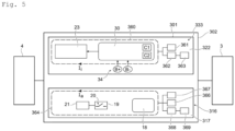
Fig. 5 ] lafigure 5 représente schématiquement le dispositif d'affichage et la carte mère selon un quatrième mode de réalisation. - En référence aux
figures 1 et 2 , le dispositif d'affichage 1 selon un premier mode de réalisation est ici intégré dans un compteur électrique 2 qui est utilisé pour mesurer l'énergie électrique consommée par une installation 3 et fournie par un réseau de distribution 4. Le réseau de distribution peut être un réseau monophasé ou polyphasé. - Le compteur électrique 2 comporte un boîtier 5 (fabriqué en plastique par exemple) comprenant une portion de boîtier principale, appelée embase 6, et un capot 7. L'embase 6 comprend une face arrière 8 du boîtier 5, destinée à être appliquée contre un mur et fixée au mur. Le capot 7 comprend une face externe 9, qui est aussi la face avant du boîtier 5, qui est visible et accessible par l'abonné ou par un opérateur.
- Ici, par « interne », on entend du côté de l'intérieur du compteur 2 lorsque celui-ci est assemblé, et par « externe », on entend du côté de l'extérieur.
- Le capot 7, qui est fixé à l'embase 6 lorsque le boîtier 5 est assemblé, est amovible et peut être retiré et éloigné de l'embase 6 par un opérateur pour ouvrir le boîtier 5.
- Le capot 7 comprend une ouverture rectangulaire 11 formée dans son épaisseur e, qui a des dimensions plus importantes au niveau de la face externe 9 du capot 7 qu'au niveau de sa face interne 12. Cet agrandissement de l'ouverture 11 forme un épaulement définissant une surface 14 sur laquelle est positionnée une plaque transparente 15 (fabriquée par exemple en verre ou en plastique transparent) qui s'étend donc sur une portion de la face avant 9 du boîtier 5.
- Le compteur 2 comporte un circuit principal, qui est ici une carte électrique 16 dite « carte mère ». La carte mère 16 comprend un circuit imprimé 17 qui est positionné à proximité et parallèlement à la face interne de l'embase 6.
- Un certain nombre de composants sont montés sur le circuit imprimé 17 de la carte mère 16, parmi lesquels un microcontrôleur 18 appelé ici « microcontrôleur métrologie » qui, notamment, acquiert les mesures réalisées par les différents capteurs du compteur 2 et réalise certains traitements sur lesdites mesures.
- Le compteur 2 intègre de plus un organe de coupure 19. L'organe de coupure 19 est destiné à couper sélectivement le courant fourni à l'installation 3. L'organe de coupure 19 comprend un interrupteur 20 pour chaque phase du réseau de distribution 4.
- L'organe de coupure 19 est piloté par un microcontrôleur 21 appelé « microcontrôleur applicatif », qui est monté sur la carte mère 16.
- Le dispositif d'affichage 1 comporte quant à lui un circuit imprimé 22, distinct de celui de la carte mère 16, et un écran, en l'occurrence un écran LCD 23 qui est monté (ici soudé) sur la face externe du circuit imprimé 22.
- Le dispositif d'affichage 1 est intégré de la manière suivante dans le compteur 2. Les bords du circuit imprimé 22 sont fixés par emboîtage élastique au capot 7. Le capot 7 comporte ainsi des pattes 24 qui s'étendent depuis la face interne 12 du capot 7 perpendiculairement à celle-ci, et qui sont munies chacune à son extrémité libre d'un crochet 25. Une surface d'accueil 26 est définie sur la face interne 12 du capot 7. La surface d'accueil 26 s'étend autour de l'ouverture 11. Les pattes 24 s'étendent de part et d'autre de la surface d'accueil 26. Les crochets 25 comprennent chacun une surface 27 inclinée vers la face interne 12 du capot 7 et située du côté de la surface d'accueil 26.
- Lors du montage du dispositif d'affichage 1, les bords du circuit imprimé 22 appuient et glissent contre les surfaces 27 des crochets 25, qui s'écartent légèrement pour laisser passer le circuit imprimé 22, qui vient se positionner parallèlement à la face interne 12 et contre la surface d'accueil 26. L'écran LCD 23 est alors positionné dans l'ouverture formée dans l'épaisseur e du capot 7, de sorte que sa surface externe est entièrement recouverte par la plaque transparente 15.
- Lorsque le compteur 2 est assemblé, le circuit imprimé 22 est positionné parallèlement au circuit imprimé 17 de la carte mère 16, à une distance typiquement comprise entre 1 cm et 6 cm de celui-ci.
- Le dispositif d'affichage 1 comporte de plus un composant d'affichage, en l'occurrence un microcontrôleur 30 appelé ici « microcontrôleur LCD », un circuit d'alimentation 31, une première interface de communication 33 et une deuxième interface de communication 34. Tous ces composants sont montés sur le circuit imprimé 22.
- Le microcontrôleur LCD 30 pilote entièrement l'écran LCD 23, en l'activant et le désactivant, en l'alimentant, et en lui fournissant les données à afficher au format adéquat.
- Le circuit d'alimentation 31 comporte une pile 35, positionnée dans un logement fixé sur la face interne du circuit imprimé 22. Le circuit d'alimentation 31, et donc la pile 35, alimente la totalité du dispositif d'affichage 1. Comme l'écran LCD 23 est éteint la plupart du temps, il n'y a pas de contrainte critique concernant la durée de vie de la pile 35.
- Le circuit d'alimentation 31 comporte aussi deux capacités C1, C2, montées sur le microcontrôleur LCD 30 (sur 2 pins différentes du microcontrôleur 30), qui permettent de fournir un complément d'alimentation ponctuel pour assurer la fourniture de courant lors de pics de tirage de courant par l'écran LCD 23. Chacune des capacités C1 et C2 est par exemple formée par un condensateur ayant une valeur de capacité de 1 µF, en parallèle avec un condensateur ayant une valeur de capacité de 68pF.
- La première interface de communication 33 est agencée pour recevoir des données montantes émises par la carte mère 16 via une communication sans fil. La communication sans fil est ici une communication optique.
- La première interface de communication 33 comprend un récepteur de signaux lumineux, ici en l'occurrence une photodiode infrarouge 36.
- La carte mère 16 comprend quant à elle un émetteur de signaux lumineux, ici en l'occurrence une LED (diode électroluminescente) infrarouge 38.
- La photodiode 36 et la LED 38 sont positionnées en regard l'une de l'autre.
- La première interface de communication 33 du dispositif d'affichage 1 comprend de plus un émetteur de signaux lumineux, ici en l'occurrence une LED infrarouge 40.
- La carte mère 16 comprend quant à elle un récepteur de signaux lumineux, ici en l'occurrence une photodiode infrarouge 42.
- La LED 40 et la photodiode 42 sont positionnées en regard l'une de l'autre.
- La première interface de communication 33 est donc aussi agencée pour transmettre des données descendantes à la carte mère 16.
- Le compteur 1 comprend de plus un guide optique 43, monté entre le circuit imprimé 22 du dispositif d'affichage 1 et le circuit imprimé 17 de la carte mère 16, de manière à entourer les LEDs 38, 40, les photodiodes 36, 42, et donc le canal de communication optique sur toute sa longueur.
- Le guide optique 43 a une forme cylindrique et permet de guider et de concentrer les signaux lumineux entre les LEDs 38, 40 et les photodiodes 36, 42.
- La deuxième interface de communication 34 est agencée pour produire des données descendantes à partir d'une interaction avec une entité externe au compteur 2, et pour transmettre lesdites données descendantes à la première interface de communication 33 (qui elle-même les transmet à la carte mère 16). L'entité externe est ici un individu (abonné ou opérateur a priori).
- La deuxième interface de communication 34 comprend ici deux boutons-poussoirs : un bouton « + » (B+) et un bouton « - » (B-), qui sont montés sur le circuit imprimé 22, qui sont positionnés à proximité de l'écran LCD 23, et qui peuvent être actionnés depuis l'extérieur du compteur 2.
- L'abonné ou l'opérateur, en appuyant sur ces boutons, peut faire défiler les informations affichées sur l'écran LCD 23. L'abonné ou l'opérateur peut aussi, en réalisant un appui long sur le bouton B+, commander la fermeture de l'organe de coupure 19.
- La deuxième interface de communication 34 transforme donc ces commandes en données descendantes qui sont alors transmises à la carte mère 16 via la première interface de communication 33, pour que la carte mère 16 effectue les actions requises. Ces actions requises consistent en l'occurrence à faire afficher par l'écran LCD 23 les informations demandées en les transmettant au dispositif d'affichage 1 via la première interface de communication 33, ou à commander la fermeture de l'organe de coupure 19.
- La communication sans fil est donc une communication bidirectionnelle de type full-duplex qui utilise une couche physique infrarouge (LED et photodiode dans chaque sens de communication). La communication met en oeuvre une liaison série. Le protocole utilisé est par exemple le HDLC (pour High-Level Data Link Control), basé sur des trames HDLC en asynchrone (avec par exemple un débit de 9600 bits/s et des caractères asynchrones 8 bits sans parité) . La suite de caractères à transmettre est passée dans la payload (que l'on traduit parfois par charge utile, ou données utiles) de la trame HDLC montante (de la carte mère 16 vers le dispositif d'affichage 1) octet par octet en ASCII. Dans le sens descendant, pour refermer l'organe de coupure 19, on envoie par exemple une trame HDLC comportant l'octet de payload 0x01.
- Le dispositif d'affichage 1 est donc un bloc unique, tout intégré, autonome en énergie, qui peut être monté et assemblé préalablement à l'assemblage du compteur 2 et qui peut avoir sa propre référence (Part Number). Il peut aussi être intégré avec le capot 7 pour former un bloc unique ayant sa propre référence.
- Ainsi, lors de l'assemblage du compteur 2, il suffit de fixer le dispositif d'affichage 1 au capot 7 (s'ils ne sont pas déjà intégrés en un unique bloc), ici par emboîtage élastique, puis de fixer le capot 7 à l'embase 6 du boîtier 5. Aucune connexion électrique ne doit être réalisée entre le dispositif d'affichage 1 et le reste du compteur 2 lors de l'assemblage, ce qui facilite grandement le montage et réduit nettement le coût du compteur 2. Il est de plus possible de monter des composants sur la surface du circuit imprimé 17 de la carte mère 16, qui est située dans la projection de la surface du circuit imprimé 22 du dispositif d'affichage 1, car ladite surface est accessible directement lorsque le capot 7 est retiré du boîtier 2.
- En référence à la
figure 3 , dans un deuxième mode de réalisation, le dispositif d'affichage 101 du compteur 102 ne comprend plus la deuxième interface de communication 34, et donc plus de boutons-poussoirs B+, B-. La deuxième interface de communication 34, et donc les boutons-poussoirs B+, B- ne sont plus positionnés sur le circuit imprimé 122 du dispositif d'affichage 101, mais sur le circuit imprimé 117 de la carte mère 116. Ici, les boutons-poussoirs B+, B-sont connectés au microcontrôleur applicatif 21. - La communication descendante n'est donc plus requise (communication unidirectionnelle suffisante), de sorte que la première interface de communication 133 du dispositif d'affichage 101 ne comporte plus la LED 40, et la carte mère 116 ne comporte plus la photodiode 42.
- En référence à la
figure 4 , dans un troisième mode de réalisation, le dispositif d'affichage 201 du compteur 202 ne comporte plus de pile 35. - Cette fois, le circuit d'alimentation 231 comprend un connecteur 50, ici de type HE14 femelle, monté sur le circuit imprimé 222 du dispositif d'affichage 201.
- La carte mère 216 comporte un connecteur complémentaire 51, donc HE14 mâle, positionné en regard du connecteur 50.
- Ainsi, lors de l'assemblage du compteur 202, le dispositif d'affichage 201 est positionné de sorte que le connecteur 50 vient se connecter au connecteur 51. Le dispositif d'affichage 201 est donc alimenté par la carte mère 216 via les connecteurs 50, 51.
- Ce mode de réalisation est avantageux par rapport à l'art antérieur, car les connecteurs 50, 51 ne comportent chacun que deux contacts : Vcc (3,3 V par exemple) et 0 V. Les connecteurs 50, 51 prennent donc très peu de place sur les circuits imprimés et notamment sur celui de la carte mère 216.
- Il y a donc bien une liaison par contact entre le dispositif d'affichage 201 et la carte mère 216, mais cette liaison est peu encombrante, peu coûteuse, simple à manipuler, et ne nécessite pas d'opération de dessoudage pour éloigner le dispositif d'affichage 201 (et le capot 7) de la carte mère 216.
- En référence à la
figure 5 , dans un quatrième mode de réalisation, le dispositif d'affichage 301 du compteur 302 ne comporte pas de pile 35 ni de connecteur 50. - Cette fois, la communication sans fil entre le dispositif d'affichage 301 et la carte mère 316 est une communication radiofréquence.
- La première interface de communication 333 du dispositif d'affichage 301 comporte un enroulement secondaire 360, formé ici par des pistes imprimées sur la face interne du circuit imprimé 322. La première interface de communication 333 comporte aussi un ou des condensateurs 361 connectés à l'enroulement secondaire 360, ainsi qu'un transistor 362 relié à une charge 363.
- De même la carte mère 316 comporte un enroulement primaire 364, formé ici par des pistes imprimées s'étendant sur la face interne du circuit imprimé 317, et qui, avantageusement, a les mêmes dimensions et est disposé coaxialement à l'enroulement secondaire 360. La carte mère 316 comporte aussi un ou des condensateurs 366 connectés à l'enroulement primaire 364, un amplificateur 367, ainsi qu'un transistor 368 relié à une charge 369.
- Les valeurs d'inductance des enroulements 360, 364 et les valeurs de capacité des condensateurs 361, 366 sont définies de sorte que, lorsque le compteur 302 est assemblé et que les enroulements 360, 364 sont positionnés l'un en face de l'autre, les enroulements 360, 364 et les condensateurs 361, 366 forment un circuit résonant à une fréquence prédéfinie (par exemple 13,56 MHz).
- La communication sans fil et l'alimentation du dispositif d'affichage 301 sont réalisées via l'enroulement primaire 364 et l'enroulement secondaire 360.
- L'amplificateur 367 produit un courant d'alimentation Ia qui circule dans l'enroulement primaire 364, et qui génère un champ magnétique qui induit un courant induit Ii dans l'enroulement secondaire 360. Le courant induit Ii alimente le dispositif d'affichage 301.
- La communication montante se fait via le transistor 368 qui connecte ou déconnecte la charge 369 de l'enroulement primaire 364 pour produire des états hauts et bas des données montantes. Cela module le champ magnétique, et donc le courant induit Ii. Cette modulation est captée par un circuit de démodulation de la première interface de communication 333 (non représenté) qui récupère alors les données montantes. De même, la communication descendante se fait via le transistor 362 qui connecte ou déconnecte la charge 363 de l'enroulement secondaire 360 et donc module le champ magnétique, ce qui module le courant d'alimentation Ia. Cette modulation est captée par un circuit de démodulation de la carte mère 316 (non représenté) qui récupère alors les données descendantes. La communication est cette fois une communication half-duplex.
- Bien entendu, l'invention n'est pas limitée aux modes de réalisation décrits mais englobe toute variante entrant dans le champ de l'invention tel que défini par les revendications.
- L'écran n'est pas nécessairement un écran LCD, il peut s'agir de tout type d'écran (LED, OLED, etc.).
- Le dispositif d'affichage pourrait être fixé de manière différente au capot, et par exemple par vissage.
- Les différents modes de réalisation peuvent être combinés. En particulier, on pourrait avoir :
- une pile dans le dispositif d'affichage, associée à tout autre moyen d'alimentation (via les connecteurs, sans fil) ;
- une communication sans fil et une alimentation sans fil utilisant des techniques différentes (par exemple optique pour la communication et radiofréquence pour l'alimentation) ;
- une communication montante et une communication descendante dans la première interface de communication, même sans deuxième interface de communication (le microcontrôleur LCD pourrait par exemple transmettre des données de monitoring à la carte mère) ;
- etc.
- La communication optique n'utilise pas forcément des signaux infrarouges. Les composants utilisés peuvent être différents (par exemple des phototransistors au lieu des photodiodes).
- La communication radiofréquence peut être réalisée à une ou des fréquences différentes de celle citée ici. Les enroulements peuvent être formés non pas par des pistes imprimées sur les circuits imprimés du dispositif d'affichage et de la carte mère, mais par des bobines de fil de cuivre, des antennes patchs, etc. La communication radiofréquence n'utilise pas nécessairement une modulation d'amplitude.
- L'entité externe, avec laquelle communique la deuxième interface de communication du dispositif d'affichage, n'est pas nécessairement un individu. Il pourrait s'agit d'un équipement externe, un concentrateur de données ou un smartphone par exemple, la deuxième interface de communication comprenant alors dans ce cas des moyens de communications adaptés (radiofréquences par exemple).
- Le circuit principal n'est pas forcément une carte mère d'un compteur (ou autre), il peut s'agir de tout dispositif électrique agencé pour transmettre des données à afficher à un écran.
- L'équipement intégrant le dispositif d'affichage n'est pas nécessairement un compteur mais peut être tout type d'équipement.
Claims (12)
- Dispositif d'affichage (1 ; 101 ; 201 ; 301), agencé pour être intégré dans un équipement (2 ; 102 ; 202 ; 302) qui comprend de plus un boîtier (5) et un circuit principal (16 ; 116 ; 216 ; 316) intégré dans le boîtier, le dispositif d'affichage comportant :- un écran (23), agencé pour être positionné sur le boîtier ;- un circuit imprimé (22), sur lequel est monté l'écran et sur lequel sont montés :o une première interface de communication (33 ; 133), agencée pour recevoir des données montantes émises par le circuit principal via une communication sans fil ;o un composant d'affichage (30), agencé pour faire afficher les données montantes par l'écran ;o un circuit d'alimentation (31), agencé pour alimenter le dispositif d'affichage.
- Dispositif d'affichage selon la revendication 1, dans lequel la première interface de communication (33) est aussi agencée pour transmettre des données descendantes au circuit principal (16) via la communication sans fil, le dispositif d'affichage comprenant de plus une deuxième interface de communication (34) agencée pour produire les données descendantes à partir d'une interaction avec une entité externe à l'équipement et pour transmettre lesdites données descendantes à la première interface de communication (33).
- Dispositif d'affichage selon l'une des revendications précédentes, dans lequel la communication sans fil est une communication optique.
- Dispositif d'affichage selon l'une des revendications 1 ou 2, dans lequel la communication sans fil est une communication radiofréquence.
- Dispositif d'affichage selon l'une des revendications précédentes, dans lequel le circuit principal (316) peut comporter un enroulement primaire (364) et le circuit d'alimentation comporte un enroulement secondaire (360), le circuit principal pouvant générer un courant d'alimentation (Ia) qui induit un courant induit (Ii) dans l'enroulement secondaire, ledit courant induit étant utilisé pour alimenter le dispositif d'affichage.
- Dispositif d'affichage selon les revendications 4 et 5, dans lequel la communication sans fil est aussi mise en oeuvre via l'enroulement primaire (364) et l'enroulement secondaire (360) .
- Dispositif d'affichage selon l'une des revendications précédentes, dans lequel le circuit d'alimentation (31) comporte une pile (35).
- Dispositif d'affichage selon l'une des revendications précédentes, dans lequel le circuit d'alimentation (231) comporte un connecteur de type HE14 (50).
- Capot (7) de boîtier (5) d'un équipement (2), comprenant un dispositif d'affichage selon l'une des revendications précédentes.
- Equipement (2 ; 102 ; 202 ; 302) comportant un boîtier, un circuit principal, et un dispositif d'affichage selon l'une des revendications 1 à 8.
- Equipement selon la revendication 10, dans lequel le boîtier comporte un capot auquel est fixé par emboîtement élastique le circuit imprimé (22) du dispositif d'affichage (1) .
- Equipement selon l'une des revendications 10 ou 11, l'équipement étant un compteur électrique ou un compteur d'eau.
Applications Claiming Priority (1)
| Application Number | Priority Date | Filing Date | Title |
|---|---|---|---|
| FR2311401A FR3154568A1 (fr) | 2023-10-20 | 2023-10-20 | Ecran sans fil |
Publications (1)
| Publication Number | Publication Date |
|---|---|
| EP4542369A1 true EP4542369A1 (fr) | 2025-04-23 |
Family
ID=89767079
Family Applications (1)
| Application Number | Title | Priority Date | Filing Date |
|---|---|---|---|
| EP24206357.6A Pending EP4542369A1 (fr) | 2023-10-20 | 2024-10-14 | Ecran sans fil |
Country Status (4)
| Country | Link |
|---|---|
| US (1) | US20250130073A1 (fr) |
| EP (1) | EP4542369A1 (fr) |
| CN (1) | CN119865720A (fr) |
| FR (1) | FR3154568A1 (fr) |
Citations (3)
| Publication number | Priority date | Publication date | Assignee | Title |
|---|---|---|---|---|
| CN204117570U (zh) * | 2014-06-16 | 2015-01-21 | 施耐德电气工业公司 | 电气设备的显示设备 |
| US20180335915A1 (en) * | 2016-11-21 | 2018-11-22 | Wuhan China Star Optoelectronics Technology Co., Ltd. | Notebook computer |
| CN210007742U (zh) * | 2019-07-30 | 2020-01-31 | 联想(北京)有限公司 | 电子设备 |
-
2023
- 2023-10-20 FR FR2311401A patent/FR3154568A1/fr active Pending
-
2024
- 2024-10-14 EP EP24206357.6A patent/EP4542369A1/fr active Pending
- 2024-10-15 CN CN202411437583.4A patent/CN119865720A/zh active Pending
- 2024-10-18 US US18/920,150 patent/US20250130073A1/en active Pending
Patent Citations (3)
| Publication number | Priority date | Publication date | Assignee | Title |
|---|---|---|---|---|
| CN204117570U (zh) * | 2014-06-16 | 2015-01-21 | 施耐德电气工业公司 | 电气设备的显示设备 |
| US20180335915A1 (en) * | 2016-11-21 | 2018-11-22 | Wuhan China Star Optoelectronics Technology Co., Ltd. | Notebook computer |
| CN210007742U (zh) * | 2019-07-30 | 2020-01-31 | 联想(北京)有限公司 | 电子设备 |
Also Published As
| Publication number | Publication date |
|---|---|
| US20250130073A1 (en) | 2025-04-24 |
| FR3154568A1 (fr) | 2025-04-25 |
| CN119865720A (zh) | 2025-04-22 |
Similar Documents
| Publication | Publication Date | Title |
|---|---|---|
| WO2006137337A1 (fr) | Affichage à cristaux liquides doté d’une fonction de conversion photoélectrique | |
| EP0766152A1 (fr) | Pièce d'horlogerie comportant une antenne | |
| EP2219353A1 (fr) | Téléphone portable incluant une batterie et un module de communication à champ proche | |
| FR2717626A1 (fr) | Boîtier pour lecteur de carte à microcircuit. | |
| FR3154568A1 (fr) | Ecran sans fil | |
| FR3037747A1 (fr) | Appareil electronique susceptible de communiquer par li-fi | |
| KR20130093704A (ko) | 사용자 선택형 레이저 및 이를 포함하는 광 송신기 | |
| FR2485220A1 (fr) | Bati et bloc modulaires pour instruments horaires | |
| EP2192531A1 (fr) | Circuit électrique / électronique pour connecter un dispositif à une antenne radiofréquence | |
| WO2012032066A1 (fr) | Boitier d'alimentation pour appareil de communication | |
| EP3175164A1 (fr) | Boîtier de gestion d'un dispositif de communication | |
| FR2664138A1 (fr) | Dispositif compartimentable sous forme de malette-circuit imprime en tout ou partie et portable integrant une unite de traitement informatique de donnees, de communication, d'edition. | |
| WO2019011401A1 (fr) | Appareillage electrique et module fonctionnel additionnel associe | |
| FR2943468A1 (fr) | Prise electrique et alimentation sans interruption equipee d'une telle prise | |
| JP3586574B2 (ja) | 光通信モジュール | |
| EP3652769B1 (fr) | Appareillage électrique et module fonctionnel additionnel associé | |
| WO2019011405A1 (fr) | Appareillage électrique et module fonctionnel additionnel associé | |
| CN209400078U (zh) | Ld激光器背光监测光路系统 | |
| FR2779281A1 (fr) | Adaptateur pour une unite de commande et unite de commande comportant un tel adaptateur | |
| FR2956750A1 (fr) | Lunettes a cristaux liquides et dispositif de commande associe | |
| US6803562B2 (en) | Indirect monitoring of semiconductor light source within a photonic package | |
| EP3652829A1 (fr) | Appareillage électrique et module fonctionnel additionnel associé | |
| EP3985401B1 (fr) | Dispositif de détection de présence de tension et tableau électrique comprenant un tel dispositif | |
| EP3652828A1 (fr) | Appareillage électrique et module fonctionnel additionnel associé | |
| JP2004146397A (ja) | 回路モジュールおよびネットワーク機器 |
Legal Events
| Date | Code | Title | Description |
|---|---|---|---|
| PUAI | Public reference made under article 153(3) epc to a published international application that has entered the european phase |
Free format text: ORIGINAL CODE: 0009012 |
|
| STAA | Information on the status of an ep patent application or granted ep patent |
Free format text: STATUS: EXAMINATION IS IN PROGRESS |
|
| 17P | Request for examination filed |
Effective date: 20241014 |
|
| AK | Designated contracting states |
Kind code of ref document: A1 Designated state(s): AL AT BE BG CH CY CZ DE DK EE ES FI FR GB GR HR HU IE IS IT LI LT LU LV MC ME MK MT NL NO PL PT RO RS SE SI SK SM TR |