EP4542217A1 - Road surface condition determination device and control device - Google Patents
Road surface condition determination device and control device Download PDFInfo
- Publication number
- EP4542217A1 EP4542217A1 EP23859794.2A EP23859794A EP4542217A1 EP 4542217 A1 EP4542217 A1 EP 4542217A1 EP 23859794 A EP23859794 A EP 23859794A EP 4542217 A1 EP4542217 A1 EP 4542217A1
- Authority
- EP
- European Patent Office
- Prior art keywords
- road surface
- vehicle
- sound
- surface condition
- section
- Prior art date
- Legal status (The legal status is an assumption and is not a legal conclusion. Google has not performed a legal analysis and makes no representation as to the accuracy of the status listed.)
- Pending
Links
Images

Classifications
-
- G—PHYSICS
- G01—MEASURING; TESTING
- G01W—METEOROLOGY
- G01W1/00—Meteorology
- G01W1/02—Instruments for indicating weather conditions by measuring two or more variables, e.g. humidity, pressure, temperature, cloud cover or wind speed
-
- G—PHYSICS
- G01—MEASURING; TESTING
- G01N—INVESTIGATING OR ANALYSING MATERIALS BY DETERMINING THEIR CHEMICAL OR PHYSICAL PROPERTIES
- G01N29/00—Investigating or analysing materials by the use of ultrasonic, sonic or infrasonic waves; Visualisation of the interior of objects by transmitting ultrasonic or sonic waves through the object
- G01N29/04—Analysing solids
- G01N29/12—Analysing solids by measuring frequency or resonance of acoustic waves
-
- B—PERFORMING OPERATIONS; TRANSPORTING
- B60—VEHICLES IN GENERAL
- B60W—CONJOINT CONTROL OF VEHICLE SUB-UNITS OF DIFFERENT TYPE OR DIFFERENT FUNCTION; CONTROL SYSTEMS SPECIALLY ADAPTED FOR HYBRID VEHICLES; ROAD VEHICLE DRIVE CONTROL SYSTEMS FOR PURPOSES NOT RELATED TO THE CONTROL OF A PARTICULAR SUB-UNIT
- B60W40/00—Estimation or calculation of non-directly measurable driving parameters for road vehicle drive control systems not related to the control of a particular sub unit, e.g. by using mathematical models
- B60W40/02—Estimation or calculation of non-directly measurable driving parameters for road vehicle drive control systems not related to the control of a particular sub unit, e.g. by using mathematical models related to ambient conditions
- B60W40/06—Road conditions
-
- G—PHYSICS
- G01—MEASURING; TESTING
- G01N—INVESTIGATING OR ANALYSING MATERIALS BY DETERMINING THEIR CHEMICAL OR PHYSICAL PROPERTIES
- G01N29/00—Investigating or analysing materials by the use of ultrasonic, sonic or infrasonic waves; Visualisation of the interior of objects by transmitting ultrasonic or sonic waves through the object
- G01N29/04—Analysing solids
- G01N29/041—Analysing solids on the surface of the material, e.g. using Lamb, Rayleigh or shear waves
-
- G—PHYSICS
- G01—MEASURING; TESTING
- G01N—INVESTIGATING OR ANALYSING MATERIALS BY DETERMINING THEIR CHEMICAL OR PHYSICAL PROPERTIES
- G01N29/00—Investigating or analysing materials by the use of ultrasonic, sonic or infrasonic waves; Visualisation of the interior of objects by transmitting ultrasonic or sonic waves through the object
- G01N29/14—Investigating or analysing materials by the use of ultrasonic, sonic or infrasonic waves; Visualisation of the interior of objects by transmitting ultrasonic or sonic waves through the object using acoustic emission techniques
-
- G—PHYSICS
- G01—MEASURING; TESTING
- G01N—INVESTIGATING OR ANALYSING MATERIALS BY DETERMINING THEIR CHEMICAL OR PHYSICAL PROPERTIES
- G01N29/00—Investigating or analysing materials by the use of ultrasonic, sonic or infrasonic waves; Visualisation of the interior of objects by transmitting ultrasonic or sonic waves through the object
- G01N29/44—Processing the detected response signal, e.g. electronic circuits specially adapted therefor
- G01N29/4454—Signal recognition, e.g. specific values or portions, signal events, signatures
-
- G—PHYSICS
- G01—MEASURING; TESTING
- G01N—INVESTIGATING OR ANALYSING MATERIALS BY DETERMINING THEIR CHEMICAL OR PHYSICAL PROPERTIES
- G01N29/00—Investigating or analysing materials by the use of ultrasonic, sonic or infrasonic waves; Visualisation of the interior of objects by transmitting ultrasonic or sonic waves through the object
- G01N29/44—Processing the detected response signal, e.g. electronic circuits specially adapted therefor
- G01N29/46—Processing the detected response signal, e.g. electronic circuits specially adapted therefor by spectral analysis, e.g. Fourier analysis or wavelet analysis
-
- B—PERFORMING OPERATIONS; TRANSPORTING
- B60—VEHICLES IN GENERAL
- B60W—CONJOINT CONTROL OF VEHICLE SUB-UNITS OF DIFFERENT TYPE OR DIFFERENT FUNCTION; CONTROL SYSTEMS SPECIALLY ADAPTED FOR HYBRID VEHICLES; ROAD VEHICLE DRIVE CONTROL SYSTEMS FOR PURPOSES NOT RELATED TO THE CONTROL OF A PARTICULAR SUB-UNIT
- B60W50/00—Details of control systems for road vehicle drive control not related to the control of a particular sub-unit, e.g. process diagnostic or vehicle driver interfaces
- B60W2050/0001—Details of the control system
- B60W2050/0043—Signal treatments, identification of variables or parameters, parameter estimation or state estimation
- B60W2050/0057—Frequency analysis, spectral techniques or transforms
-
- B—PERFORMING OPERATIONS; TRANSPORTING
- B60—VEHICLES IN GENERAL
- B60W—CONJOINT CONTROL OF VEHICLE SUB-UNITS OF DIFFERENT TYPE OR DIFFERENT FUNCTION; CONTROL SYSTEMS SPECIALLY ADAPTED FOR HYBRID VEHICLES; ROAD VEHICLE DRIVE CONTROL SYSTEMS FOR PURPOSES NOT RELATED TO THE CONTROL OF A PARTICULAR SUB-UNIT
- B60W2420/00—Indexing codes relating to the type of sensors based on the principle of their operation
- B60W2420/54—Audio sensitive means, e.g. ultrasound
-
- B—PERFORMING OPERATIONS; TRANSPORTING
- B60—VEHICLES IN GENERAL
- B60W—CONJOINT CONTROL OF VEHICLE SUB-UNITS OF DIFFERENT TYPE OR DIFFERENT FUNCTION; CONTROL SYSTEMS SPECIALLY ADAPTED FOR HYBRID VEHICLES; ROAD VEHICLE DRIVE CONTROL SYSTEMS FOR PURPOSES NOT RELATED TO THE CONTROL OF A PARTICULAR SUB-UNIT
- B60W2422/00—Indexing codes relating to the special location or mounting of sensors
-
- B—PERFORMING OPERATIONS; TRANSPORTING
- B60—VEHICLES IN GENERAL
- B60W—CONJOINT CONTROL OF VEHICLE SUB-UNITS OF DIFFERENT TYPE OR DIFFERENT FUNCTION; CONTROL SYSTEMS SPECIALLY ADAPTED FOR HYBRID VEHICLES; ROAD VEHICLE DRIVE CONTROL SYSTEMS FOR PURPOSES NOT RELATED TO THE CONTROL OF A PARTICULAR SUB-UNIT
- B60W2520/00—Input parameters relating to overall vehicle dynamics
- B60W2520/10—Longitudinal speed
-
- B—PERFORMING OPERATIONS; TRANSPORTING
- B60—VEHICLES IN GENERAL
- B60W—CONJOINT CONTROL OF VEHICLE SUB-UNITS OF DIFFERENT TYPE OR DIFFERENT FUNCTION; CONTROL SYSTEMS SPECIALLY ADAPTED FOR HYBRID VEHICLES; ROAD VEHICLE DRIVE CONTROL SYSTEMS FOR PURPOSES NOT RELATED TO THE CONTROL OF A PARTICULAR SUB-UNIT
- B60W2555/00—Input parameters relating to exterior conditions, not covered by groups B60W2552/00, B60W2554/00
- B60W2555/20—Ambient conditions, e.g. wind or rain
-
- B—PERFORMING OPERATIONS; TRANSPORTING
- B60—VEHICLES IN GENERAL
- B60W—CONJOINT CONTROL OF VEHICLE SUB-UNITS OF DIFFERENT TYPE OR DIFFERENT FUNCTION; CONTROL SYSTEMS SPECIALLY ADAPTED FOR HYBRID VEHICLES; ROAD VEHICLE DRIVE CONTROL SYSTEMS FOR PURPOSES NOT RELATED TO THE CONTROL OF A PARTICULAR SUB-UNIT
- B60W2556/00—Input parameters relating to data
- B60W2556/45—External transmission of data to or from the vehicle
-
- B—PERFORMING OPERATIONS; TRANSPORTING
- B60—VEHICLES IN GENERAL
- B60W—CONJOINT CONTROL OF VEHICLE SUB-UNITS OF DIFFERENT TYPE OR DIFFERENT FUNCTION; CONTROL SYSTEMS SPECIALLY ADAPTED FOR HYBRID VEHICLES; ROAD VEHICLE DRIVE CONTROL SYSTEMS FOR PURPOSES NOT RELATED TO THE CONTROL OF A PARTICULAR SUB-UNIT
- B60W50/00—Details of control systems for road vehicle drive control not related to the control of a particular sub-unit, e.g. process diagnostic or vehicle driver interfaces
- B60W50/08—Interaction between the driver and the control system
- B60W50/14—Means for informing the driver, warning the driver or prompting a driver intervention
-
- B—PERFORMING OPERATIONS; TRANSPORTING
- B60—VEHICLES IN GENERAL
- B60W—CONJOINT CONTROL OF VEHICLE SUB-UNITS OF DIFFERENT TYPE OR DIFFERENT FUNCTION; CONTROL SYSTEMS SPECIALLY ADAPTED FOR HYBRID VEHICLES; ROAD VEHICLE DRIVE CONTROL SYSTEMS FOR PURPOSES NOT RELATED TO THE CONTROL OF A PARTICULAR SUB-UNIT
- B60W60/00—Drive control systems specially adapted for autonomous road vehicles
- B60W60/005—Handover processes
- B60W60/0059—Estimation of the risk associated with autonomous or manual driving, e.g. situation too complex, sensor failure or driver incapacity
-
- G—PHYSICS
- G01—MEASURING; TESTING
- G01N—INVESTIGATING OR ANALYSING MATERIALS BY DETERMINING THEIR CHEMICAL OR PHYSICAL PROPERTIES
- G01N2291/00—Indexing codes associated with group G01N29/00
- G01N2291/02—Indexing codes associated with the analysed material
- G01N2291/023—Solids
- G01N2291/0232—Glass, ceramics, concrete or stone
-
- G—PHYSICS
- G01—MEASURING; TESTING
- G01N—INVESTIGATING OR ANALYSING MATERIALS BY DETERMINING THEIR CHEMICAL OR PHYSICAL PROPERTIES
- G01N2291/00—Indexing codes associated with group G01N29/00
- G01N2291/04—Wave modes and trajectories
- G01N2291/044—Internal reflections (echoes), e.g. on walls or defects
-
- Y—GENERAL TAGGING OF NEW TECHNOLOGICAL DEVELOPMENTS; GENERAL TAGGING OF CROSS-SECTIONAL TECHNOLOGIES SPANNING OVER SEVERAL SECTIONS OF THE IPC; TECHNICAL SUBJECTS COVERED BY FORMER USPC CROSS-REFERENCE ART COLLECTIONS [XRACs] AND DIGESTS
- Y02—TECHNOLOGIES OR APPLICATIONS FOR MITIGATION OR ADAPTATION AGAINST CLIMATE CHANGE
- Y02T—CLIMATE CHANGE MITIGATION TECHNOLOGIES RELATED TO TRANSPORTATION
- Y02T10/00—Road transport of goods or passengers
- Y02T10/60—Other road transportation technologies with climate change mitigation effect
- Y02T10/72—Electric energy management in electromobility
Definitions
- This disclosure relates to a road surface condition determination device and a control device.
- Patent Document 1 proposes a detection method that emits ultrasonic waves at the road surface, determines the acoustic impedance of the road surface from the reflectivity, and compares it with the standard acoustic impedance to identify the substance present on the road surface.
- Patent Document 1 In the case of an autonomous vehicle, the vehicle may make a decision on whether or not to continue driving automatically based on the road conditions from the perspective of safety. For this reason, there is a need for technology that can accurately estimate the road surface condition on which the vehicle is in motion.
- the technology described in Patent Document 1 requires a transmitter/receiver fixed to a support so that the distance to the road surface is known in order to transmit and receive ultrasonic waves. The distance between the vehicle and the road surface changes while the vehicle is in motion, and it is also difficult to retrofit a large device that emits ultrasonic waves to the chassis. For these reasons, it is difficult to apply the detection method in Patent Document 1 to vehicles.
- the object of the present disclosure made in view of the above circumstances is to provide a road surface condition determination device and a control device that can estimate road surface condition with high accuracy using a simple configuration.
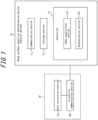
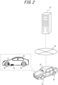
- Figures 1 and 2 are drawings that illustrate an exemplary configuration of a road surface condition determination system.
- the road surface condition determination system includes a road surface condition determination device 10.
- Figure 1 is a block diagram that includes an example of the internal configuration of the road surface condition determination device 10.
- Figure 2 illustrates the overall configuration of the road surface condition determination system.
- the road surface condition determination device 10 is a device that determines the condition of the road surface on which a vehicle 20 is in motion. Although the details will be described later, the road surface condition determination device 10 determines (estimates) the road surface condition based on information about reflected sound of the sound generated by the vehicle 20.
- the road surface condition refers to the condition of the road surface, and in this embodiment, it is classified into four categories: "Dry”, “Wet", “Ice” and "Snow”.
- the road surface condition is not limited to these four categories, and for example, some categories may be omitted, or further categories may be included, such as a category to distinguish between paved roads and gravel roads.
- the “Dry” indicates that the road surface is dry.
- the "Wet” indicates that the road surface is wet.
- the “Ice” indicates that the road surface is frozen.
- the “Snow” indicates that the road surface is covered in snow.
- the sound is not limited to those with frequencies in the audible range, and includes those in the range exceeding 20 kHz, for example.
- the operating sound refers to the sound produced by the operation of a device, and includes noise.
- the road surface condition determination device 10 comprises a communication section 11, a storage section 12, and a controller 13.
- the controller 13 comprises a data acquisition section 131 and a determination section 132.
- the road surface condition determination device 10 may be, for example, a computer in terms of its hardware configuration. The details of the components of the road surface condition determination device 10 are described later.
- the road surface condition determination device 10 may constitute a road surface condition determination system together with at least one of the devices installed in the vehicle 20 (a data collection section 70 and an in-vehicle communication section 80) which are connected to the network 40.
- the network 40 is the Internet, for example.
- the vehicle 20 is not limited to a specific type of vehicle, and may be a passenger car, a truck, a taxi, or a bus, for example.
- the vehicle 20 is described as an electric vehicle with an automatic driving function, however, it does not have to have an automatic driving function, and it may be a hybrid vehicle, for example.
- the vehicle 20 comprises the data collection section 70 and the in-vehicle communication section 80.
- the data collection section 70 collects sound data that includes information on the reflected sound of the sound generated by the vehicle 20.
- the data collection section 70 is attached to the vehicle 20 and includes a microphone in this embodiment, but is not limited to this.
- the data collection section 70 may include a device that can detect the sound of the specific frequency other than a microphone.
- the data collection section 70 may be configured to include a cavity resonator, a resonator, or a pressure sensor instead of a microphone.
- the cavity resonator may be an air column resonator with a tube length equal to one quarter of the wavelength of the specific frequency.
- the cost of the data acquisition section 70 may be reduced by using a cavity resonator and others instead of a microphone.
- the microphone which is the data collection section 70, is attached to the vehicle 20 so that it faces the road surface and picks up reflected sound from the road surface.
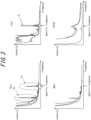
- Figure 3 illustrates an example of the frequency spectrum of the sound in the vehicle 20.
- the vertical axis indicates signal strength (sound strength).
- the horizontal axis indicates frequency.
- the sounds in the vehicle 20 include sounds of various frequencies, such as the sound emitted from the vehicle 20 and mainly reflected by the road surface, as well as noise while the vehicle is in motion, and have different characteristics depending on the road surface condition.
- peaks sharp changes such as P1 and P2
- peaks that are not present in the Wet and Snow are seen in the Dry and Ice.
- the inventor analyzed the data in more detail and found that when the road surface condition is Dry or Ice, there is a peak (P1) at a specific frequency in a high-frequency range, and that even when the vehicle 20 is in motion, it is possible to detect the peak (P1) without being affected much by noise such as running sound.
- the high-frequency range is not limited to a specific frequency band, but is generally 5 kHz or higher.
- another peak (P2) can also be seen, but this is at a low frequency that is not in the high-frequency range, and it may not be detected due to the influence of noise such as running sound.
- the inverter 21 is a device that converts direct current power from the battery into alternating current power to drive the motor provided in the tire 30.
- the specific frequencies are generally about several kHz to several tens of kHz. Therefore, it is possible to collect sound data using the data collection section 70 and determine the road surface condition based on the presence or absence of a peak in the predetermined frequency range that includes the specific frequency of the operating sound of the inverter 21 provided in the vehicle 20. The details of the road surface condition determination will be described later.
- the in-vehicle communication section 80 outputs the sound data, including the information on the reflected sound of the sound generated by the vehicle 20, which is collected by the data collection section 70, to the road surface condition determination device 10.
- the in-vehicle communication section 80 may, for example, be configured as a wireless communication module, but is not limited to a specific device. In this embodiment, the in-vehicle communication section 80 is configured to be able to communicate with the road surface condition determination device 10 via the network 40.
- the data collection section 70 may include a temperature sensor to further collect air temperature data.
- the air temperature data includes information on the ambient temperature of the road surface.
- the in-vehicle communication section 80 also outputs the air temperature data to the road surface condition determination device 10.
- the communication section 11 is configured to include one or more communication modules that connect to the network 40.
- the communication section 11 may include a communication module that supports mobile communication standards such as 4G (4th Generation) and 5G (5th Generation).
- the communication section 11 may include a communication module that supports wireless LAN standards (for example, IEEE 802.11).
- the communication section 11 may include a communication module that corresponds to a wired LAN standard, for example.
- the storage section 12 is one or more memories.
- the memories can be, for example, semiconductor memories, magnetic memories, or optical memories, however, they are not limited to these and can be any memory.
- the storage section 12 is, for example, built into the road surface condition determination device 10, however, the storage section 12 can also be configured to be accessed externally by the road surface condition determination device 10 via an arbitrary interface.
- the storage section 12 stores various data used in the various calculations performed by the controller 13. In addition, the storage section 12 may also store the results of various calculations and intermediate data executed by the controller 13. In this embodiment, the storage section 12 stores information on the specific frequency of the vehicle 20 and the predetermined frequency range that includes the specific frequency. Since the specific frequency can vary depending on the vehicle 20, it is preferable that it be identified based on measurements of the operating sound of the inverter 21, etc., before the road surface condition is determined, and that the information be stored in the storage section 12.
- the controller 13 is one or more processors.
- the processor may be, for example, a general-purpose processor or a dedicated processor specialized for a particular process, however, it is not limited to these and may be any processor.
- the controller 13 controls the overall operation of the road surface condition determination device 10.
- the road surface condition determination device 10 may have the following software configuration.
- One or more programs used to control the operation of the road surface condition determination device 10 are stored in the storage section 12.
- the program stored in the storage section 12 is read by the processor in the controller 13, the program makes the controller 13 function as the data acquisition section 131 and the determination section 132.
- the data acquisition section 131 acquires the sound data, including the information on the reflected sound of the sound generated by the vehicle 20, collected by the data acquisition section 70 installed in the vehicle 20.
- the data acquisition section 131 may acquire air temperature data.
- the data acquisition section 131 may acquire the air temperature data collected by the data collection section 70 when the data collection section 70 includes a temperature sensor.
- the data acquisition section 131 may acquire air temperature data contained in the weather information via the network 40.
- the data acquisition section 131 may acquire information from the storage section 12 on the specific frequency of the vehicle 20 and the predetermined frequency range that includes the specific frequency.
- the data acquisition section 131 outputs the acquired data and others to the determination section 132.
- the determination section 132 determines the condition of the road surface based on the presence or absence of a peak in the predetermined frequency range in the acquired sound data.
- the determination section 132 may generate a frequency spectrum such as the one illustrated in Figure 3 , for example, from the sound data.
- the determination section 132 extracts the predetermined frequency range from the frequency spectrum and determines the presence or absence of a peak in the predetermined frequency range.
- the determination of the presence or absence of a peak may be performed using a known method, and is not limited to a specific method.
- the determination section 132 may extract the maximum value for the intensity and determine whether the frequency corresponding to the maximum value matches the specific frequency.
- the determination section 132 may, for example, subtract the intensity of the frequencies around (before and after) the extracted maximum value from the maximum value, and may determine that a peak (sharp change) has occurred when the value is equal to or greater than a threshold value.
- the determination section 132 can determine that the road surface is Dry or Ice if there is a peak in the predetermined frequency range.
- the determination section 132 can determine that the road surface is Wet or Snow if there are no peaks in the predetermined frequency range. For example, in the summer season, the determination section 132 may determine the condition of the road surface to be Dry if there is a peak in a predetermined frequency range, and to be Wet if there is no peak.
- the determination section 132 may further determine the condition of the road surface based on air temperature data. By using the air temperature data in combination, the determination section 132 can estimate the condition of the road surface in even finer categories.
- Table 1 provides the method for determining the road surface condition in the determination section 132 when using the air temperature data in combination.
- the "Low” air temperature means, for example, 0°C or below, and all others are indicated as "normal”.
- the predetermined frequency range includes the specific frequency of the operating sound of the inverter 21 provided in the vehicle 20, and the presence or absence of a peak at the specific frequency is used for the determination.
- the predetermined frequency range corresponds to the high-frequency range, which is not greatly affected by noise such as running sound. Therefore, in this embodiment, it is possible to estimate the road surface condition with high accuracy by using a determination that uses a frequency range that includes the specific frequency that is less affected by noise while the vehicle is in motion.
- the road surface condition determination device 10 of this embodiment is suitable for estimating the road surface condition while the vehicle 20 is in motion.
- the controller 13 may warn the driver of the vehicle 20 to switch to manual driving if it determines that the road surface condition on the road on which the vehicle 20 is in motion automatically is Ice or Snow.
- the road surface condition determination device 10 may function as a control device that controls the vehicle 20 based on the road surface condition that has been determined.
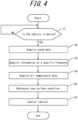
- Figure 4 is a flowchart that provides an example of the process for determining road surface condition executed by the road surface condition determination device 10.
- the road surface condition determination device 10 waits until the vehicle 20 starts to move (No in step S1).
- the road surface condition determination device 10 starts the process of determining the road surface condition.
- the peak at the specific frequency P1 in Figure 3
- the inverter 21 operates while the vehicle 20 is in motion, and the operating sound becomes loud. Therefore, if the vehicle 20 is in motion, it will be possible to detect strong reflected sound at the specific frequency, and it will be possible to accurately estimate the road surface condition.
- the road surface condition determination device 10 acquires the sound data that includes information on the reflected sound of the sound generated by the vehicle 20 (step S2). In addition, the road surface condition determination device 10 acquires information on the specific frequency from the storage section 12 (step S3). In addition, the road surface condition determination device 10 acquires the air temperature data that includes information on the ambient temperature of the road surface on which the vehicle 20 is in motion (step S4).
- the road surface condition determination device 10 determines the road surface condition based on the presence or absence of a peak in the predetermined frequency range of the sound data and the air temperature data, as illustrated in Table 1 (step S5).
- the road surface condition determination device 10 controls the vehicle 20 based on the condition of the road surface that has been determined (estimated) (step S6).
- the road surface condition determination device and the control device according to this embodiment do not require, for example, a device for emitting ultrasonic waves, and it is possible to estimate the road surface condition with high accuracy using a simple configuration.
- the control device according to this embodiment can, based on the estimated road surface condition, for example, determine whether or not to continue with automatic driving, and can control the vehicle 20 to drive safely.
- the road surface condition determination device 10 may be installed in the vehicle 20.
- the road surface condition determination device 10 can acquire sound data, etc., without going through the in-vehicle communication section 80 and the network 40.
- the road surface condition determination device 10 may acquire the sound data, etc. from the data collection section 70 using an in-vehicle network such as CAN (Controller Area Network).
- CAN Controller Area Network
- the specific frequency is not limited to the frequency of the operating sound of the inverter 21, but is any sound emitted by the vehicle 20 that shows a peak in the high-frequency range. Therefore, even for vehicles 20 that do not have inverters 21, if they have a peak in the high-frequency range that is not easily affected by noise such as running sound, the above-mentioned road surface condition determination method can be applied by setting the frequency of the sound that indicates the peak to the specific frequency.
Landscapes
- Physics & Mathematics (AREA)
- Engineering & Computer Science (AREA)
- Life Sciences & Earth Sciences (AREA)
- Biochemistry (AREA)
- Chemical & Material Sciences (AREA)
- Analytical Chemistry (AREA)
- General Health & Medical Sciences (AREA)
- General Physics & Mathematics (AREA)
- Immunology (AREA)
- Pathology (AREA)
- Health & Medical Sciences (AREA)
- Acoustics & Sound (AREA)
- Signal Processing (AREA)
- Mathematical Physics (AREA)
- Automation & Control Theory (AREA)
- Mechanical Engineering (AREA)
- Transportation (AREA)
- Environmental & Geological Engineering (AREA)
- Spectroscopy & Molecular Physics (AREA)
- Atmospheric Sciences (AREA)
- Biodiversity & Conservation Biology (AREA)
- Ecology (AREA)
- Environmental Sciences (AREA)
- Investigating Or Analyzing Materials By The Use Of Ultrasonic Waves (AREA)
Abstract
Description
- This disclosure relates to a road surface condition determination device and a control device.
- Conventionally, technologies have been proposed for grasping road conditions so that road administrators and others can carry out traffic restrictions, maintenance, improvements, and the like without requiring a great deal of effort. For example,
Patent Document 1 proposes a detection method that emits ultrasonic waves at the road surface, determines the acoustic impedance of the road surface from the reflectivity, and compares it with the standard acoustic impedance to identify the substance present on the road surface. - PTL 1:
JP H8-075711 A - In the case of an autonomous vehicle, the vehicle may make a decision on whether or not to continue driving automatically based on the road conditions from the perspective of safety. For this reason, there is a need for technology that can accurately estimate the road surface condition on which the vehicle is in motion. The technology described in
Patent Document 1 requires a transmitter/receiver fixed to a support so that the distance to the road surface is known in order to transmit and receive ultrasonic waves. The distance between the vehicle and the road surface changes while the vehicle is in motion, and it is also difficult to retrofit a large device that emits ultrasonic waves to the chassis. For these reasons, it is difficult to apply the detection method inPatent Document 1 to vehicles. - The object of the present disclosure made in view of the above circumstances is to provide a road surface condition determination device and a control device that can estimate road surface condition with high accuracy using a simple configuration.
-
- (1) A road surface condition determination device according to one embodiment of the present disclosure is a road surface condition determination device that determines a condition of a road surface on which a vehicle is in motion, comprising a data acquisition section that acquires sound data, including information on reflected sound of sound generated by the vehicle, which is collected by a data collection section installed on the vehicle, and a determination section that determines the condition of the road surface based on presence or absence of a peak in a predetermined frequency range in the acquired sound data.
- (2) As one embodiment of the present disclosure, in (1), the data acquisition section acquires air temperature data that includes information on ambient temperature of the road surface, and the determination section further determines the condition of the road surface based on the air temperature data.
- (3) As one embodiment of the present disclosure, in (1) or (2), the predetermined frequency range includes a specific frequency of operating sound of an inverter provided on the vehicle.
- (4) As one embodiment of the present disclosure, in (1) to (3), the determination section determines the condition of the road surface while the vehicle is in motion.
- (5) A control device according to one embodiment of the present disclosure is a control device installed in a vehicle and controls the vehicle, that comprises a data acquisition section that acquires sound data, including information on reflected sound of sound generated by the vehicle, which is collected by a data collection section installed on the vehicle; and a determination section that determines the condition of the road surface, on which the vehicle is in motion, based on presence or absence of a peak in a predetermined frequency range in the acquired sound data, and controls the vehicle based on the condition of the road surface that has been determined.
- According to this disclosure, it is possible to provide a road surface condition determination device and a control device that can estimate road surface condition with high accuracy using a simple configuration.
- In the accompanying drawings:
-
FIG. 1 is a drawing that illustrates an exemplary configuration of a road surface condition determination system, including a road surface condition determination device; -
FIG. 2 is another drawing that illustrates the exemplary configuration of the road surface condition determination system inFigure 1 ; -
FIG. 3 is a drawing that illustrates an example of the frequency spectrum of sound in a vehicle; -
FIG. 4 is a flowchart that illustrates an example of the process for determining road surface condition; and -
FIG. 5 is a drawing that illustrates another exemplary configuration of a road surface condition determination system, including a road surface condition determination device. - The following is an explanation of a road surface condition determination device and a control device in accordance with one embodiment of the present disclosure, with reference to the drawings. The same or equivalent parts in each drawing are marked with the same symbol/numeral. In the description of this embodiment, the description of the same or corresponding parts will be omitted or simplified as appropriate.
-
Figures 1 and2 are drawings that illustrate an exemplary configuration of a road surface condition determination system. The road surface condition determination system includes a road surfacecondition determination device 10.Figure 1 is a block diagram that includes an example of the internal configuration of the road surfacecondition determination device 10.Figure 2 illustrates the overall configuration of the road surface condition determination system. - The road surface
condition determination device 10 according to this embodiment is a device that determines the condition of the road surface on which avehicle 20 is in motion. Although the details will be described later, the road surfacecondition determination device 10 determines (estimates) the road surface condition based on information about reflected sound of the sound generated by thevehicle 20. The road surface condition refers to the condition of the road surface, and in this embodiment, it is classified into four categories: "Dry", "Wet", "Ice" and "Snow". The road surface condition is not limited to these four categories, and for example, some categories may be omitted, or further categories may be included, such as a category to distinguish between paved roads and gravel roads. The "Dry" indicates that the road surface is dry. The "Wet" indicates that the road surface is wet. The "Ice" indicates that the road surface is frozen. The "Snow" indicates that the road surface is covered in snow. In addition, in the description of this disclosure, the sound is not limited to those with frequencies in the audible range, and includes those in the range exceeding 20 kHz, for example. In addition, the operating sound refers to the sound produced by the operation of a device, and includes noise. - The road surface
condition determination device 10 comprises acommunication section 11, astorage section 12, and acontroller 13. Thecontroller 13 comprises adata acquisition section 131 and adetermination section 132. The road surfacecondition determination device 10 may be, for example, a computer in terms of its hardware configuration. The details of the components of the road surfacecondition determination device 10 are described later. - The road surface
condition determination device 10 may constitute a road surface condition determination system together with at least one of the devices installed in the vehicle 20 (adata collection section 70 and an in-vehicle communication section 80) which are connected to thenetwork 40. Thenetwork 40 is the Internet, for example. Here, thevehicle 20 is not limited to a specific type of vehicle, and may be a passenger car, a truck, a taxi, or a bus, for example. In this embodiment, thevehicle 20 is described as an electric vehicle with an automatic driving function, however, it does not have to have an automatic driving function, and it may be a hybrid vehicle, for example. - In this embodiment, the
vehicle 20 comprises thedata collection section 70 and the in-vehicle communication section 80. Thedata collection section 70 collects sound data that includes information on the reflected sound of the sound generated by thevehicle 20. Thedata collection section 70 is attached to thevehicle 20 and includes a microphone in this embodiment, but is not limited to this. As explained below, it is necessary to collect the intensity of sound of a specific frequency as the sound data, and thedata collection section 70 may include a device that can detect the sound of the specific frequency other than a microphone. For example, thedata collection section 70 may be configured to include a cavity resonator, a resonator, or a pressure sensor instead of a microphone. For example, the cavity resonator may be an air column resonator with a tube length equal to one quarter of the wavelength of the specific frequency. The cost of thedata acquisition section 70 may be reduced by using a cavity resonator and others instead of a microphone. - As illustrated in
Figure 2 , in this embodiment, the microphone, which is thedata collection section 70, is attached to thevehicle 20 so that it faces the road surface and picks up reflected sound from the road surface. Here,Figure 3 illustrates an example of the frequency spectrum of the sound in thevehicle 20. The vertical axis indicates signal strength (sound strength). The horizontal axis indicates frequency. The sounds in thevehicle 20 include sounds of various frequencies, such as the sound emitted from thevehicle 20 and mainly reflected by the road surface, as well as noise while the vehicle is in motion, and have different characteristics depending on the road surface condition. As illustrated inFigure 3 , peaks (sharp changes such as P1 and P2) that are not present in the Wet and Snow are seen in the Dry and Ice. The inventor analyzed the data in more detail and found that when the road surface condition is Dry or Ice, there is a peak (P1) at a specific frequency in a high-frequency range, and that even when thevehicle 20 is in motion, it is possible to detect the peak (P1) without being affected much by noise such as running sound. Here, the high-frequency range is not limited to a specific frequency band, but is generally 5 kHz or higher. In the Dry, another peak (P2) can also be seen, but this is at a low frequency that is not in the high-frequency range, and it may not be detected due to the influence of noise such as running sound. When the inventor conducted further analysis, it was found that the peak (P1) at the specific frequency was largely due to the operating sound of aninverter 21 provided in the vehicle 20 (seeFig. 2 ). Theinverter 21 is a device that converts direct current power from the battery into alternating current power to drive the motor provided in thetire 30. There may be fluctuations in the specific frequency depending on vehicles, as there are individual differences in the operating sound ofinverters 21, however, the specific frequencies are generally about several kHz to several tens of kHz. Therefore, it is possible to collect sound data using thedata collection section 70 and determine the road surface condition based on the presence or absence of a peak in the predetermined frequency range that includes the specific frequency of the operating sound of theinverter 21 provided in thevehicle 20. The details of the road surface condition determination will be described later. - The in-
vehicle communication section 80 outputs the sound data, including the information on the reflected sound of the sound generated by thevehicle 20, which is collected by thedata collection section 70, to the road surfacecondition determination device 10. The in-vehicle communication section 80 may, for example, be configured as a wireless communication module, but is not limited to a specific device. In this embodiment, the in-vehicle communication section 80 is configured to be able to communicate with the road surfacecondition determination device 10 via thenetwork 40. - Here, the
data collection section 70 may include a temperature sensor to further collect air temperature data. The air temperature data includes information on the ambient temperature of the road surface. In this case, the in-vehicle communication section 80 also outputs the air temperature data to the road surfacecondition determination device 10. - The following explains the details of the components of the road surface
condition determination device 10. Thecommunication section 11 is configured to include one or more communication modules that connect to thenetwork 40. Thecommunication section 11 may include a communication module that supports mobile communication standards such as 4G (4th Generation) and 5G (5th Generation). Thecommunication section 11 may include a communication module that supports wireless LAN standards (for example, IEEE 802.11). In addition, thecommunication section 11 may include a communication module that corresponds to a wired LAN standard, for example. - The
storage section 12 is one or more memories. The memories can be, for example, semiconductor memories, magnetic memories, or optical memories, however, they are not limited to these and can be any memory. Thestorage section 12 is, for example, built into the road surfacecondition determination device 10, however, thestorage section 12 can also be configured to be accessed externally by the road surfacecondition determination device 10 via an arbitrary interface. - The
storage section 12 stores various data used in the various calculations performed by thecontroller 13. In addition, thestorage section 12 may also store the results of various calculations and intermediate data executed by thecontroller 13. In this embodiment, thestorage section 12 stores information on the specific frequency of thevehicle 20 and the predetermined frequency range that includes the specific frequency. Since the specific frequency can vary depending on thevehicle 20, it is preferable that it be identified based on measurements of the operating sound of theinverter 21, etc., before the road surface condition is determined, and that the information be stored in thestorage section 12. - The
controller 13 is one or more processors. The processor may be, for example, a general-purpose processor or a dedicated processor specialized for a particular process, however, it is not limited to these and may be any processor. Thecontroller 13 controls the overall operation of the road surfacecondition determination device 10. - Here, the road surface
condition determination device 10 may have the following software configuration. One or more programs used to control the operation of the road surfacecondition determination device 10 are stored in thestorage section 12. When the program stored in thestorage section 12 is read by the processor in thecontroller 13, the program makes thecontroller 13 function as thedata acquisition section 131 and thedetermination section 132. - The
data acquisition section 131 acquires the sound data, including the information on the reflected sound of the sound generated by thevehicle 20, collected by thedata acquisition section 70 installed in thevehicle 20. Thedata acquisition section 131 may acquire air temperature data. Thedata acquisition section 131 may acquire the air temperature data collected by thedata collection section 70 when thedata collection section 70 includes a temperature sensor. In addition, when thedata collection section 70 does not include a temperature sensor, thedata acquisition section 131 may acquire air temperature data contained in the weather information via thenetwork 40. In addition, thedata acquisition section 131 may acquire information from thestorage section 12 on the specific frequency of thevehicle 20 and the predetermined frequency range that includes the specific frequency. Thedata acquisition section 131 outputs the acquired data and others to thedetermination section 132. - The
determination section 132 determines the condition of the road surface based on the presence or absence of a peak in the predetermined frequency range in the acquired sound data. Thedetermination section 132 may generate a frequency spectrum such as the one illustrated inFigure 3 , for example, from the sound data. Thedetermination section 132 extracts the predetermined frequency range from the frequency spectrum and determines the presence or absence of a peak in the predetermined frequency range. The determination of the presence or absence of a peak may be performed using a known method, and is not limited to a specific method. For example, thedetermination section 132 may extract the maximum value for the intensity and determine whether the frequency corresponding to the maximum value matches the specific frequency. In addition, thedetermination section 132 may, for example, subtract the intensity of the frequencies around (before and after) the extracted maximum value from the maximum value, and may determine that a peak (sharp change) has occurred when the value is equal to or greater than a threshold value. Thedetermination section 132 can determine that the road surface is Dry or Ice if there is a peak in the predetermined frequency range. On the contrary, thedetermination section 132 can determine that the road surface is Wet or Snow if there are no peaks in the predetermined frequency range. For example, in the summer season, thedetermination section 132 may determine the condition of the road surface to be Dry if there is a peak in a predetermined frequency range, and to be Wet if there is no peak. - The
determination section 132 may further determine the condition of the road surface based on air temperature data. By using the air temperature data in combination, thedetermination section 132 can estimate the condition of the road surface in even finer categories. Table 1 provides the method for determining the road surface condition in thedetermination section 132 when using the air temperature data in combination. In Table 1, the "Low" air temperature means, for example, 0°C or below, and all others are indicated as "normal".[Table 1] Peak in predetermined frequency range Air temperature Road surface consition Yes Normal Dry No Normal Wet Yes Low Ice No Low Snow - In this way, the predetermined frequency range includes the specific frequency of the operating sound of the
inverter 21 provided in thevehicle 20, and the presence or absence of a peak at the specific frequency is used for the determination. As mentioned above, the predetermined frequency range corresponds to the high-frequency range, which is not greatly affected by noise such as running sound. Therefore, in this embodiment, it is possible to estimate the road surface condition with high accuracy by using a determination that uses a frequency range that includes the specific frequency that is less affected by noise while the vehicle is in motion. In other words, the road surfacecondition determination device 10 of this embodiment is suitable for estimating the road surface condition while thevehicle 20 is in motion. - Here, for example, the
controller 13 may warn the driver of thevehicle 20 to switch to manual driving if it determines that the road surface condition on the road on which thevehicle 20 is in motion automatically is Ice or Snow. In this way, the road surfacecondition determination device 10 may function as a control device that controls thevehicle 20 based on the road surface condition that has been determined. -
Figure 4 is a flowchart that provides an example of the process for determining road surface condition executed by the road surfacecondition determination device 10. - The road surface
condition determination device 10 waits until thevehicle 20 starts to move (No in step S1). When thevehicle 20 starts to move (YES in step S1), the road surfacecondition determination device 10 starts the process of determining the road surface condition. Here, as mentioned above, the peak at the specific frequency (P1 inFigure 3 ) is largely due to the operating sound of theinverter 21 provided in thevehicle 20. Theinverter 21 operates while thevehicle 20 is in motion, and the operating sound becomes loud. Therefore, if thevehicle 20 is in motion, it will be possible to detect strong reflected sound at the specific frequency, and it will be possible to accurately estimate the road surface condition. - The road surface
condition determination device 10 acquires the sound data that includes information on the reflected sound of the sound generated by the vehicle 20 (step S2). In addition, the road surfacecondition determination device 10 acquires information on the specific frequency from the storage section 12 (step S3). In addition, the road surfacecondition determination device 10 acquires the air temperature data that includes information on the ambient temperature of the road surface on which thevehicle 20 is in motion (step S4). - The road surface
condition determination device 10 determines the road surface condition based on the presence or absence of a peak in the predetermined frequency range of the sound data and the air temperature data, as illustrated in Table 1 (step S5). - The road surface
condition determination device 10 controls thevehicle 20 based on the condition of the road surface that has been determined (estimated) (step S6). - As described above, the road surface condition determination device and the control device according to this embodiment do not require, for example, a device for emitting ultrasonic waves, and it is possible to estimate the road surface condition with high accuracy using a simple configuration. In addition, the control device according to this embodiment can, based on the estimated road surface condition, for example, determine whether or not to continue with automatic driving, and can control the
vehicle 20 to drive safely. - The embodiments of the present disclosure have been described based on the various drawings and examples, however, it should be noted that a person skilled in the art would be able to easily make modifications and alterations based on the present disclosure. Therefore, it should be noted that such modifications and alterations are included within the scope of this disclosure. For example, the functions contained in each component or each step, etc. can be rearranged so that they do not contradict logically, and it is possible to combine multiple components or steps, etc. into one or split them into multiple components or steps, etc. The embodiments of the present disclosure may also be realized as a program executed by a processor provided in a device, and a storage medium having the program recorded thereon.
- The configuration of the road surface
condition determination device 10 and the road surface condition determination system illustrated inFigures 1 and2 are just one example, and the present disclosure is are not limited to the configuration illustrated inFigures 1 and2 . For example, the road surfacecondition determination device 10 may be installed in thevehicle 20. As illustrated inFigure 5 , when the road surfacecondition determination device 10 is installed in thevehicle 20, the road surfacecondition determination device 10 can acquire sound data, etc., without going through the in-vehicle communication section 80 and thenetwork 40. The road surfacecondition determination device 10 may acquire the sound data, etc. from thedata collection section 70 using an in-vehicle network such as CAN (Controller Area Network). - In addition, the specific frequency is not limited to the frequency of the operating sound of the
inverter 21, but is any sound emitted by thevehicle 20 that shows a peak in the high-frequency range. Therefore, even forvehicles 20 that do not haveinverters 21, if they have a peak in the high-frequency range that is not easily affected by noise such as running sound, the above-mentioned road surface condition determination method can be applied by setting the frequency of the sound that indicates the peak to the specific frequency. -
- 10
- Road surface condition determination device
- 11
- Communication section
- 12
- Storage section
- 13
- Controller
- 20
- Vehicle
- 21
- Inverter
- 30
- Tire
- 40
- Network
- 70
- Data collection section
- 80
- In-vehicle communication section
- 131
- Data acquisition section
- 132
- Determination section
Claims (5)
- A road surface condition determination device that determines a condition of a road surface on which a vehicle is in motion, comprisinga data acquisition section that acquires sound data, including information on reflected sound of sound generated by the vehicle, which is collected by a data collection section installed on the vehicle, anda determination section that determines the condition of the road surface based on presence or absence of a peak in a predetermined frequency range in the acquired sound data.
- The road surface condition determination device as described in claim 1, wherein the data acquisition section acquires air temperature data that includes information on ambient temperature of the road surface, and
the determination section further determines the condition of the road surface based on the air temperature data. - The road surface condition determination device as described in claim 1 or 2, wherein the predetermined frequency range includes a specific frequency of operating sound of an inverter provided on the vehicle.
- The road surface condition determination device as described in any one of claims 1 to 3, wherein the determination section determines the condition of the road surface while the vehicle is in motion.
- A control device installed in a vehicle and controls the vehicle, comprisinga data acquisition section that acquires sound data, including information on reflected sound of sound generated by the vehicle, which is collected by a data collection section installed on the vehicle; anda determination section that determines the condition of the road surface, on which the vehicle is in motion, based on presence or absence of a peak in a predetermined frequency range in the acquired sound data, andcontrolling the vehicle based on the condition of the road surface that has been determined.
Applications Claiming Priority (2)
| Application Number | Priority Date | Filing Date | Title |
|---|---|---|---|
| JP2022138709A JP7870690B2 (en) | 2022-08-31 | 2022-08-31 | Road surface condition determination device and control device |
| PCT/JP2023/022799 WO2024048024A1 (en) | 2022-08-31 | 2023-06-20 | Road surface condition determination device and control device |
Publications (2)
| Publication Number | Publication Date |
|---|---|
| EP4542217A1 true EP4542217A1 (en) | 2025-04-23 |
| EP4542217A4 EP4542217A4 (en) | 2025-10-15 |
Family
ID=90099380
Family Applications (1)
| Application Number | Title | Priority Date | Filing Date |
|---|---|---|---|
| EP23859794.2A Pending EP4542217A4 (en) | 2022-08-31 | 2023-06-20 | ROAD SURFACE CONDITION DETERMINING DEVICE AND CONTROL DEVICE |
Country Status (4)
| Country | Link |
|---|---|
| US (1) | US20250283855A1 (en) |
| EP (1) | EP4542217A4 (en) |
| JP (1) | JP7870690B2 (en) |
| WO (1) | WO2024048024A1 (en) |
Family Cites Families (15)
| Publication number | Priority date | Publication date | Assignee | Title |
|---|---|---|---|---|
| JP3473158B2 (en) * | 1995-03-22 | 2003-12-02 | 住友電気工業株式会社 | Road surface condition detection device |
| US5852243A (en) * | 1997-07-21 | 1998-12-22 | J-Squared, Llc | Method and apparatus for detecting a road pavement surface condition |
| JP3904733B2 (en) | 1998-07-31 | 2007-04-11 | 株式会社小野測器 | Road drainage measuring device |
| JP2003083943A (en) | 2001-09-13 | 2003-03-19 | Pasuko:Kk | Ultrasonic pavement porosity detection method and device |
| DE10259979A1 (en) | 2002-12-19 | 2004-07-15 | Daimlerchrysler Ag | A method for determining a road condition while driving a Kraffahrzeugs |
| JP4149903B2 (en) | 2003-11-21 | 2008-09-17 | 社団法人 雪センター | Road surface condition determination method and apparatus |
| US8618921B2 (en) | 2009-11-10 | 2013-12-31 | GM Global Technology Operations LLC | Method and system for identifying wet pavement using tire noise |
| JP5657917B2 (en) | 2010-05-19 | 2015-01-21 | 株式会社ブリヂストン | Road surface condition estimation method |
| US8760003B2 (en) * | 2010-08-02 | 2014-06-24 | Denso Corporation | Vehicle-use power supply control apparatus and control apparatus for controlling electric rotating machine mounted on vehicle as main engine |
| FR3015036B1 (en) * | 2013-12-18 | 2016-01-22 | Michelin & Cie | METHOD OF ACOUSTICALLY DETECTING THE CONDITION OF ROAD AND TIRE |
| DE102015208364A1 (en) | 2015-05-06 | 2016-11-10 | Robert Bosch Gmbh | A method for determining properties of a ground on which a vehicle operable away from paved roads is moved |
| JP2019167760A (en) | 2018-03-26 | 2019-10-03 | パイオニア株式会社 | Analyzer, vehicle, analysis method, program and storage medium |
| DE102018206741A1 (en) * | 2018-05-02 | 2019-11-07 | Robert Bosch Gmbh | Ultrasound system of a vehicle |
| DE102019101129A1 (en) | 2019-01-17 | 2020-07-23 | Valeo Schalter Und Sensoren Gmbh | Determining the surface quality of a surface covering used by a motor vehicle |
| DE102019202079A1 (en) | 2019-07-10 | 2021-01-14 | Robert Bosch Gmbh | Method for determining a road condition by means of an ultrasonic sensor of a means of locomotion |
-
2022
- 2022-08-31 JP JP2022138709A patent/JP7870690B2/en active Active
-
2023
- 2023-06-20 EP EP23859794.2A patent/EP4542217A4/en active Pending
- 2023-06-20 US US19/105,036 patent/US20250283855A1/en active Pending
- 2023-06-20 WO PCT/JP2023/022799 patent/WO2024048024A1/en not_active Ceased
Also Published As
| Publication number | Publication date |
|---|---|
| WO2024048024A1 (en) | 2024-03-07 |
| EP4542217A4 (en) | 2025-10-15 |
| JP2024034470A (en) | 2024-03-13 |
| US20250283855A1 (en) | 2025-09-11 |
| JP7870690B2 (en) | 2026-06-05 |
Similar Documents
| Publication | Publication Date | Title |
|---|---|---|
| US10365248B2 (en) | Method for acoustic detection of the condition of the road and the tire | |
| US8618921B2 (en) | Method and system for identifying wet pavement using tire noise | |
| US20150033864A1 (en) | System and method for acoustically identifying damaged sections of a route | |
| CN103434445B (en) | Vehicle is blown a whistle prompt system and method | |
| US11472237B2 (en) | Tire damage detection system and method | |
| KR20040091158A (en) | Tire-state obtaining apparatus | |
| JP2005292785A (en) | Onboard audio system and signal processing method therefor | |
| CN111856593A (en) | In-vehicle living body loss monitoring device and method | |
| US20210255296A1 (en) | Method and device for detecting a noise generated in a receive signal of an ultrasonic sensor | |
| KR20180056084A (en) | Vehicle and Controlling Method thereof | |
| US12221112B2 (en) | Apparatus for predicting friction coefficient of road surface and method thereof | |
| US20200312050A1 (en) | Control device, server, safety system, and control method of control device | |
| US20230025723A1 (en) | Method for assessing an external event on an automotive glazing | |
| CN100498846C (en) | Information collector and information collecting method for commerical passenger car | |
| EP3802157B1 (en) | Tire damage detection system and method | |
| US20250283855A1 (en) | Road surface condition determination device and control device | |
| JP5895783B2 (en) | Vehicle approach notification device | |
| US9616814B1 (en) | Vehicle security alarming system determining relative velocity between a front car and a rear car by sounds retrieved therefrom | |
| US20240402317A1 (en) | Methods and systems for lidar monitoring | |
| CN113246894A (en) | Vehicle collision detection method and device | |
| CN108344504A (en) | Noise detection system and analysis method in 8 road car of one kind | |
| CN115107649B (en) | A vehicle sound warning device based on audio enhancement | |
| CN111717143A (en) | A noise reduction control method, system and vehicle for side window | |
| US12605971B2 (en) | Method for estimating the state of wear of a tire | |
| CN120620932A (en) | Prompt method, device, vehicle, medium and program product |
Legal Events
| Date | Code | Title | Description |
|---|---|---|---|
| STAA | Information on the status of an ep patent application or granted ep patent |
Free format text: STATUS: THE INTERNATIONAL PUBLICATION HAS BEEN MADE |
|
| PUAI | Public reference made under article 153(3) epc to a published international application that has entered the european phase |
Free format text: ORIGINAL CODE: 0009012 |
|
| STAA | Information on the status of an ep patent application or granted ep patent |
Free format text: STATUS: REQUEST FOR EXAMINATION WAS MADE |
|
| 17P | Request for examination filed |
Effective date: 20250117 |
|
| AK | Designated contracting states |
Kind code of ref document: A1 Designated state(s): AL AT BE BG CH CY CZ DE DK EE ES FI FR GB GR HR HU IE IS IT LI LT LU LV MC ME MK MT NL NO PL PT RO RS SE SI SK SM TR |
|
| A4 | Supplementary search report drawn up and despatched |
Effective date: 20250916 |
|
| RIC1 | Information provided on ipc code assigned before grant |
Ipc: G01N 29/12 20060101AFI20250910BHEP Ipc: G01N 29/46 20060101ALI20250910BHEP Ipc: G01W 1/00 20060101ALI20250910BHEP Ipc: B60W 40/06 20120101ALI20250910BHEP |
|
| DAV | Request for validation of the european patent (deleted) | ||
| DAX | Request for extension of the european patent (deleted) |