EP4542158A1 - Heat transfer plate, cassette and heat exchanger - Google Patents
Heat transfer plate, cassette and heat exchanger Download PDFInfo
- Publication number
- EP4542158A1 EP4542158A1 EP23204060.0A EP23204060A EP4542158A1 EP 4542158 A1 EP4542158 A1 EP 4542158A1 EP 23204060 A EP23204060 A EP 23204060A EP 4542158 A1 EP4542158 A1 EP 4542158A1
- Authority
- EP
- European Patent Office
- Prior art keywords
- heat transfer
- port hole
- transfer plate
- groove portion
- sealing groove
- Prior art date
- Legal status (The legal status is an assumption and is not a legal conclusion. Google has not performed a legal analysis and makes no representation as to the accuracy of the status listed.)
- Withdrawn
Links
Images


Classifications
-
- F—MECHANICAL ENGINEERING; LIGHTING; HEATING; WEAPONS; BLASTING
- F28—HEAT EXCHANGE IN GENERAL
- F28F—DETAILS OF HEAT-EXCHANGE AND HEAT-TRANSFER APPARATUS, OF GENERAL APPLICATION
- F28F3/00—Plate-like or laminated elements; Assemblies of plate-like or laminated elements
- F28F3/08—Elements constructed for building-up into stacks, e.g. capable of being taken apart for cleaning
- F28F3/083—Elements constructed for building-up into stacks, e.g. capable of being taken apart for cleaning capable of being taken apart
-
- F—MECHANICAL ENGINEERING; LIGHTING; HEATING; WEAPONS; BLASTING
- F28—HEAT EXCHANGE IN GENERAL
- F28D—HEAT-EXCHANGE APPARATUS, NOT PROVIDED FOR IN ANOTHER SUBCLASS, IN WHICH THE HEAT-EXCHANGE MEDIA DO NOT COME INTO DIRECT CONTACT
- F28D9/00—Heat-exchange apparatus having stationary plate-like or laminated conduit assemblies for both heat-exchange media, the media being in contact with different sides of a conduit wall
- F28D9/0031—Heat-exchange apparatus having stationary plate-like or laminated conduit assemblies for both heat-exchange media, the media being in contact with different sides of a conduit wall the conduits for one heat-exchange medium being formed by paired plates touching each other
- F28D9/0043—Heat-exchange apparatus having stationary plate-like or laminated conduit assemblies for both heat-exchange media, the media being in contact with different sides of a conduit wall the conduits for one heat-exchange medium being formed by paired plates touching each other the plates having openings therein for circulation of at least one heat-exchange medium from one conduit to another
- F28D9/005—Heat-exchange apparatus having stationary plate-like or laminated conduit assemblies for both heat-exchange media, the media being in contact with different sides of a conduit wall the conduits for one heat-exchange medium being formed by paired plates touching each other the plates having openings therein for circulation of at least one heat-exchange medium from one conduit to another the plates having openings therein for both heat-exchange media
-
- F—MECHANICAL ENGINEERING; LIGHTING; HEATING; WEAPONS; BLASTING
- F28—HEAT EXCHANGE IN GENERAL
- F28F—DETAILS OF HEAT-EXCHANGE AND HEAT-TRANSFER APPARATUS, OF GENERAL APPLICATION
- F28F13/00—Arrangements for modifying heat-transfer, e.g. increasing, decreasing
- F28F13/06—Arrangements for modifying heat-transfer, e.g. increasing, decreasing by affecting the pattern of flow of the heat-exchange media
- F28F13/08—Arrangements for modifying heat-transfer, e.g. increasing, decreasing by affecting the pattern of flow of the heat-exchange media by varying the cross-section of the flow channels
-
- F—MECHANICAL ENGINEERING; LIGHTING; HEATING; WEAPONS; BLASTING
- F28—HEAT EXCHANGE IN GENERAL
- F28F—DETAILS OF HEAT-EXCHANGE AND HEAT-TRANSFER APPARATUS, OF GENERAL APPLICATION
- F28F9/00—Casings; Header boxes; Auxiliary supports for elements; Auxiliary members within casings
- F28F9/02—Header boxes; End plates
- F28F9/026—Header boxes; End plates with static flow control means, e.g. with means for uniformly distributing heat exchange media into conduits
-
- F—MECHANICAL ENGINEERING; LIGHTING; HEATING; WEAPONS; BLASTING
- F28—HEAT EXCHANGE IN GENERAL
- F28F—DETAILS OF HEAT-EXCHANGE AND HEAT-TRANSFER APPARATUS, OF GENERAL APPLICATION
- F28F9/00—Casings; Header boxes; Auxiliary supports for elements; Auxiliary members within casings
- F28F9/02—Header boxes; End plates
- F28F2009/0285—Other particular headers or end plates
- F28F2009/029—Other particular headers or end plates with increasing or decreasing cross-section, e.g. having conical shape
-
- F—MECHANICAL ENGINEERING; LIGHTING; HEATING; WEAPONS; BLASTING
- F28—HEAT EXCHANGE IN GENERAL
- F28F—DETAILS OF HEAT-EXCHANGE AND HEAT-TRANSFER APPARATUS, OF GENERAL APPLICATION
- F28F2230/00—Sealing means
-
- F—MECHANICAL ENGINEERING; LIGHTING; HEATING; WEAPONS; BLASTING
- F28—HEAT EXCHANGE IN GENERAL
- F28F—DETAILS OF HEAT-EXCHANGE AND HEAT-TRANSFER APPARATUS, OF GENERAL APPLICATION
- F28F2250/00—Arrangements for modifying the flow of the heat exchange media, e.g. flow guiding means; Particular flow patterns
-
- F—MECHANICAL ENGINEERING; LIGHTING; HEATING; WEAPONS; BLASTING
- F28—HEAT EXCHANGE IN GENERAL
- F28F—DETAILS OF HEAT-EXCHANGE AND HEAT-TRANSFER APPARATUS, OF GENERAL APPLICATION
- F28F2275/00—Fastening; Joining
- F28F2275/06—Fastening; Joining by welding
Definitions
- the invention relates to a heat transfer plate, a cassette comprising two such heat transfer plates and a heat exchanger comprising a plurality of such cassettes.
- Plate heat exchangers typically comprises two end plates in between which a number of heat transfer plates are arranged in a stack or pack.
- the heat transfer plates of a PHE may be of the same or different types and they may be stacked in different ways.
- the heat transfer plates are stacked with the front side and the back side of one heat transfer plate facing the back side and the front side, respectively, of other heat transfer plates, and every other heat transfer plate turned upside down in relation to the rest of the heat transfer plates.
- this is referred to as the heat transfer plates being "rotated" in relation to each other.
- the heat transfer plates are stacked with the front side and the back side of one heat transfer plate facing the front side and back side, respectively, of other heat transfer plates, and every other heat transfer plate turned upside down in relation to the rest of the heat transfer plates. Typically, this is referred to as the heat transfer plates being "flipped" in relation to each other.
- the heat transfer plates are typically "flipped" in relation to each other and welded in pairs to form tight cassettes, and gaskets are arranged between the cassettes.
- the end plates, and therefore the cassettes, are pressed towards each other by some kind of tightening means whereby the gaskets seal between the cassettes.
- Parallel flow channels are formed between the heat transfer plates, one channel between each pair of adjacent heat transfer plates.
- Two fluids of initially different temperatures which are fed, by means of equipment like pumps, to/from the PHE through inlets/outlets, can flow alternately through every second channel for transferring heat from one fluid to the other, which fluids enter/exit the channels through inlet/outlet port holes in the heat transfer plates, which inlet/outlet port holes form inlet/outlet ports which communicate with the inlets/outlets of the PHE.
- channels defined by welds and channels defined by gaskets which welds and gaskets typically extend along outer edges and the inlet/outlet port holes of the heat transfer plates.
- the channels defined by welds can, and should preferably, withstand a much higher pressure than the channels defined by gaskets.
- WO2009/082336 discloses a PHE comprising heat transfer plates permanently connected in pairs by means of welds to form cassettes, and gaskets sealing between the cassettes, i.e. a semi-welded heat exchanger. Even if this heat exchanger works well, it may still have room for improvement.
- a heat transfer plate comprises an upper end part, a center part and a lower end part arranged in succession along a longitudinal center axis of the heat transfer plate.
- the upper end part comprises a first port hole and a second port hole
- the lower end part comprises a third port hole and a fourth port hole.
- the center part comprises a heat transfer area provided with a heat transfer corrugation pattern comprising ridges and valleys as seen from a first side of the heat transfer plate.
- the ridges and valleys extend in and between imaginary parallel first and second planes.
- the first side of the heat transfer plate faces the first plane and an opposite second side of the heat transfer plate faces the second plane.
- the heat transfer plate further comprises, as seen from the first side, a sealing groove.
- the sealing groove comprises a field sealing groove portion enclosing the heat transfer area and two of the first, second, third and fourth port holes.
- the heat transfer plate further comprises a gasket groove,
- the gasket groove comprises a field gasket groove portion enclosing the heat transfer area and two of the first, second, third and fourth port holes which are not enclosed by the field sealing groove portion.
- the heat transfer plate is characterized in that the first port hole and the third port hole are non-circular and the second port hole and the fourth port hole are circular.
- the first and the third port holes may be uniform, in other words have the same shape.
- the first and the third port holes may have the same size.
- the second and the fourth port holes may be uniform, in other words have the same shape. Further, the second and the fourth port holes may have the same size.
- the field sealing groove and the field gasket groove may at least partly coincide.
- the circular second and fourth port holes are dedicated to one and the same fluid while the non-circular first and third port holes are dedicated to one and the same, and another fluid.
- the circular port holes just like the non-circular port holes, may be arranged on opposite sides of the longitudinal center axis of the heat transfer plate. Such a port hole placement may enable a heat transfer plate of so-called diagonal flow type, and a heat exchanger comprising heat transfer plates according to the invention which are "rotated" in relation to each other. However, such a heat exchanger may require heat transfer plates of two different designs.
- first port hole and the third port hole are arranged on one side of the longitudinal center axis of the heat transfer plate, while the second port hole and the fourth port hole are arranged on another side of the longitudinal center axis of the heat transfer plate.
- a port hole placement may enable a heat transfer plate of so-called parallel flow type, and a heat exchanger comprising heat transfer plates according to the invention which are "flipped" in relation to each other.
- the heat transfer plate may be arranged to be permanently joined to another heat transfer plate along the sealing groove, for instance by a weld extending within the sealing groove, to form a cassette.
- the heat transfer plate may be so configured that the field sealing groove portion of the sealing groove encloses the circular second and fourth port holes.
- Such a configuration means that the port holes dedicated for the fluid arranged to flow inside the cassette are circular. This is beneficial since, as said before, circular port holes are optimum from a mechanical strength point of view and the channels inside the cassettes preferably should withstand a relatively high pressure.
- the field gasket groove portion of the gasket groove which gasket groove is arranged to accommodate a gasket for sealing abutment against another heat transfer plate, may enclose the first port hole and the third port hole.
- the port holes dedicated for the fluid arranged to flow outside the cassette are non-circular. This may be beneficial since, as said before, non-circular port holes may be optimum as regards other characteristics than mechanical strength, for example thermal performance, and the channels outside the cassettes preferably should withstand a relatively low pressure.
- the design of the heat transfer plate may be such that a bottom of the field sealing groove portion, along at least more than half of a length of the field sealing groove portion, extends in the second plane. Such a design may facilitate permanent joining of the heat transfer plate to another heat transfer plate.
- the heat transfer plate may be such that the sealing groove further comprises, as seen from the first side of the heat transfer plate, a first ring sealing groove portion enclosing the first port hole and a third ring sealing groove portion enclosing the third port hole.
- a bottom of the first ring sealing groove portion may, along at least more than half of a length of the first ring sealing groove portion, extend in the second plane.
- a bottom of the third ring sealing groove portion may, along at least more than half of a length of the third ring sealing groove portion, extend in the second plane.
- the heat transfer plate may be so configured that the gasket groove further comprises a second ring gasket groove portion enclosing the second port hole and a fourth ring gasket groove portion enclosing the fourth port hole.
- a bottom of the second ring gasket groove portion may, along at least more than half of a length of the second ring gasket groove portion, extend between the first plane and the second plane.
- a bottom of the fourth ring gasket groove portion may, along at least more than half of a length of the fourth ring gasket groove portion, extend between the first plane and the second plane.
- Such a design may enable a fluid flow between the second port hole and the fourth port hole on the second side of the heat transfer plate.
- the heat transfer plate may be so designed that each of the first and the third port hole has only one symmetry axis. This may facilitate a relatively mechanically straightforward construction of a plate heat exchanger comprising the heat transfer plate.
- the heat transfer plate may be such that the first port hole is arranged within a first portion of the heat transfer plate defined by a first short side, a first long side, the longitudinal center axis and a transverse center axis, of the heat transfer plate, wherein a reference point of the first port hole coincides with a center point of a biggest imaginary circle that can be fitted into the first port hole.
- the first port hole may have different forms. However, according to one embodiment of the invention, a form of the first port hole is defined by a number of corner points of an imaginary plane geometric figure of which at least one is displaced from an arc of the circle, and the same number of curved lines having no straight parts and connecting the corner points.
- a first corner point of the corner points is arranged closest to a transition between the first short side and the first long side and on a first distance from the reference point.
- a second one of the corner points is arranged closest to the first corner point in a clockwise direction and on a second distance from the reference point.
- a third one of the corner points is arranged closest to the first corner point in a counterclockwise direction and on a third distance from the reference point.
- the plane geometric figure can be of many different types, for example a triangle, a quadrangle, a pentagon and so on.
- the number of corner points or extreme points, and thus curved lines may differ from being two and up.
- the first port hole will have a contour without any straight portions. This is beneficial since it will result in relatively low bending stresses around the port hole. A fluid flowing through the port hole strives to bend the first port hole into a circular form. Thus, if the port hole had straight portions, that would result in relatively high bending stresses in the heat exchanger plate.
- Each of the curved lines connects two of the corner points.
- the first port hole Since at least one of the corner points is displaced from the arc of the imaginary circle, the first port hole will be non-circular.
- the feature that the second and third corner points are closest to the first corner point in a clockwise and a counterclockwise direction, respectively, expresses the relative positioning of the first, second and third corner points following the contour of the first port hole.
- the first port hole form described above may enable a first port hole that is adapted to the design of the rest of the heat transfer plate and that is larger than the circular second and fourth port holes by sacrifice of surface of the heat transfer plate that does not contribute considerably to the heat transfer performance or thermal performance of the heat transfer plate.
- the heat transfer plate may be such that the first port hole has one symmetry axis only which extends through the first corner point and the reference point. This may facilitate a relatively mechanically straightforward construction of a plate heat exchanger comprising the heat transfer plate.
- the number of corner points and curved lines is equal to three.
- the corresponding plane geometric figure could be a triangle.
- This embodiment is suitable for many conventional heat transfer plates with an essentially rectangular shape and the port holes arranged at the corners of heat exchanger plate.
- the curved lines may be concave or outwards bulging as seen from the reference point of the first port hole. Such a design enables a relatively large port hole area which is associated with a relatively low pressure drop.
- the first distance between the first corner point and the reference point may be smaller than the second distance between the second corner point and the reference point and/or the third distance between the third corner point and the reference point.
- the shape of the port hole can be adapted to the design of the rest of the heat transfer plate. More particularly, depending on the heat transfer plate design, there may be more room for displacing the second and third corner points to increase the port hole area than for displacing the first corner point.
- a cassette according to the invention comprises two heat transfer plates as described above.
- the second side of one of the two heat transfer plates faces the second side of another one of the two heat transfer plates and said another one of the two heat transfer plates is rotated 180 degrees around a normal of said another one of the two heat transfer plates.
- one of the heat transfer plates is rotated 180 degrees around its transverse center axis.
- the two heat transfer plates are welded to each other along the sealing grooves.
- a heat exchanger according to the invention comprises a plurality of aligned cassettes according to the above.
- the heat exchanger further comprises gaskets arranged in the gasket grooves between each two adjacent ones of the cassettes.
- portion, part, section, etc. of the heat transfer plate extends in a certain plane, it is the main extension of the portion, part, section, etc. that is referred to.
- a portion, part, section, etc. may locally have an extension deviating from the main extension, for example at a transition to another adjacent portion, part, section, etc.
- Figs. 1 and 2 show a semi-welded plate heat exchanger 2 as described by way of introduction. It comprises a frame plate 4, a pressure plate 6, a pack of heat transfer plates 8, fluid inlets and outlets 10, tightening means 12, an upper bar 14 and a lower bar 16.
- the plate 8a is an essentially rectangular sheet of stainless steel. It comprises first and second opposing long sides 18, 20 and first and second opposing short sides 22, 24. Further, the plate 8a has a longitudinal center axis L extending parallel to, and halfway between, the long sides 18, 20, and a transverse center axis T extending parallel to, and halfway between, the short sides 22, 24 and thus perpendicular to the longitudinal center axis L.
- the plate 8a has a first side 30 (illustrated in Figs. 3 and 4 ) and an opposing second side 32 (illustrated in Fig. 4 ). Further, the plate 8a comprises an upper end part 34, a center part 36 and a lower end part 38 arranged in succession along the longitudinal center axis L of the heat transfer plate 8a.
- the upper end part 34 comprises a first port hole 40, a second port hole 42, a first adiabatic area 39, a second adiabatic area 41 and an upper distribution area 44.
- the center part 36 comprises a heat transfer area 46.
- the lower end part 38 comprises a third port hole 48, a fourth port hole 50, a third adiabatic area 49, a fourth adiabatic area 51 and a lower distribution area 52.
- the first and third port holes 40 and 48 are arranged on one side of the longitudinal center axis L while the second and the fourth port holes 42 and 50 are arranged on the other side of the longitudinal center axis L.
- the heat transfer plate 8a is pressed, in a conventional manner, in a pressing tool, to be given a desired structure, such as different corrugation patterns within different portions of the heat transfer plate.
- the corrugation patterns are optimized for the specific functions of the respective plate portions.
- the upper and lower distribution areas 44 and 52 each comprises a distribution corrugation pattern adapted for optimized fluid distribution across the heat transfer plate 8a.
- the heat transfer area 46 comprises a heat transfer corrugation pattern adapted for optimized heat transfer between two fluids flowing on opposite sides of the heat transfer plate 8a.
- the first, second, third and fourth adiabatic areas 39, 41, 49 and 51 each comprises a corrugation pattern optimized from an adiabatic point of view.
- the plate 8a comprises an outer edge part 54 extending along an outer edge 56 of the plate.
- the outer edge part 54 comprises corrugations 58 extending in and between imaginary parallel first and second planes P1 and P2 ( Fig. 4 ), which first plane P1 and second plane P2 face the first side 30 and the second side 32, respectively, of the plate 8a.
- These corrugations 58 are arranged to abut corrugations of adjacent plates 8b and 8c in the plate pack of the plate heat exchanger 2.
- the heat transfer corrugation pattern comprises corrugations, more particularly alternately arranged ridges 60 and valleys 62 as seen from the first side 30 of the plate 8a, extending in and between the first and second planes P1 and P2.
- These ridges 60 and valleys 62 are arranged to abut ridges and valleys of the adjacent plates 8b and 8c in the plate pack of the plate heat exchanger 2.
- the distribution corrugation pattern comprises corrugations arranged to abut corrugations of the adjacent plates in the plate pack of the plate heat exchanger 2. However, this is not further discussed herein.
- a bottom 66b of the first ring sealing groove portion 64b extends in the second plane P2 along the complete length of the first ring sealing groove portion 64b.
- the third ring sealing groove portion 64c encloses the third port hole 48.
- a bottom 66c of the third ring sealing groove portion 64c extends in the second plane P2 along the complete length of the third ring sealing groove portion 64c.
- a gasket groove 68 for receiving a gasket 59 (comprising a field gasket portion and two ring gasket portions).
- the gasket groove 68 comprises a field gasket groove portion 68a, a second ring gasket groove portion 68b and a fourth ring gasket groove portion 68c.
- the field gasket groove portion 68a encloses the heat transfer area 46 and the first and third port holes 40 and 48.
- the field gasket groove portion 68a partly coincides with the field sealing groove portion 64a. Therefore, a bottom 70a of the field gasket groove portion 68a extends in the second plane P2 ( Fig.
- the field gasket groove portion 68a coincides with the field sealing groove portion 64a.
- the bottom 70a of the field gasket groove portion 68a extends in the second plane P2 everywhere except for at two diagonal sections 68a' of the field gasket groove portion 68a along which the bottom 70a extends between, here halfway between, the first plane P1 and the second plane P2.
- the second ring gasket groove portion 68b encloses the second port hole 42.
- a bottom 70b of the second ring gasket groove portion 68b extends between, here halfway between, the first plane P1 and the second plane P2 along the complete length of the second ring gasket groove portion 68b.
- the fourth ring gasket groove portion 68c encloses the fourth port hole 50.
- a bottom 70c of the fourth ring gasket groove portion 68c extends between, here halfway between, the first plane P1 and the second plane P2 along the complete length of the fourth ring gasket groove portion 68c.
- the plates 8 are arranged with the first side 30 and the second side 32 of one plate 8 facing the first side and the second side, respectively, of the neighboring heat transfer plates. Further, every second plate 8 is turned upside-down or rotated 180 degrees, in relation to a reference orientation, around a normal direction N which is normal to the figure plane of Fig. 3 . In other words, every second plate 8 is rotated 180 degrees around its transverse center axis.
- Fig. 4 illustrates the contact between the corrugations 58 of the outer edge parts 54 ( Fig.3 ) of the plate 8a and two adjacent plates 8b and 8c of the plate pack of the plate heat exchanger 2.
- the plates 8 of the plate pack are welded together in pairs, second side 32 to second side 32, along their respective sealing grooves 64, to form cassettes 57.
- Fig. 5 shows one of the cassettes 57 comprising the plate 8a illustrated in Fig. 3 and the plate 8c visible in Fig. 4 (but not in Fig. 5 ).
- the welded cassettes 57 are separated by gaskets 59, at least a majority of which gaskets 59 are similar, one of these gaskets 59 being illustrated in Fig. 5 .
- the gaskets 59 are accommodated in the gasket grooves 68 of the plates 8, as is illustrated in Fig. 5 .
- the heat exchanger 2 comprises channels of two different types; welded channels inside the cassettes 57 and gasketed channels between the cassettes 57.
- the third and fourth port holes 48 and 50 are mirror inversions of the first and second port holes 40 and 42, respectively, and will not be separately described.
- the first port hole 40 is arranged within a first portion 72 of the heat transfer plate 8a defined by the first long side 18, the first short side 22, the longitudinal center axis L and the transverse center axis T.
- the first port hole 40 is illustrated, very schematically, in Fig. 6 . It has a form defined by first, second and third corner points 74, 76 and 78, respectively, of an imaginary plane geometric figure 80 in the form of a triangle (dashed lines). Further, these corner points 74, 76 and 78 are connected by first, second and third thoroughly curved lines 82, 84 and 86, respectively, which are concave as seen from within the first port hole 40.
- a reference point 88 of the first port hole 40 coincides with a center point C of a biggest imaginary circle 90 (ghost lines) that can be arranged in the first port hole 40.
- the first corner point 74 is positioned closest to a transition 92 between the first short side 22 and the first long side 18 of the heat transfer plate 8a. Further, it is arranged on a first imaginary straight line 94 extending from the reference point 88 and on a first distance d1 from the reference point 88.
- the second corner point 76 is positioned closest to the first corner point 74 in the clockwise direction. Further, it is arranged on a second imaginary straight line 96 extending from the reference point 88 and on a second distance d2 from the reference point 88.
- the third corner point 78 is positioned closest to the first corner point 74 in the counterclockwise direction. Further, it is arranged on a third imaginary straight line 98 extending from the reference point 88 and on a third distance d3 from the reference point 88.
- d2 d3 and d2 > d1.
- a first angle ⁇ 1 between the first and second imaginary straight lines 94 and 96 is smaller than a second angle ⁇ 2 between the second and third imaginary straight lines 96 and 98 and essentially equal to a third angle ⁇ 3 between the second and first imaginary straight lines 96 and 94.
- ⁇ 1 ⁇ 3 and ⁇ 1 ⁇ ⁇ 2.
- first curved line 82 connecting the first and second corner points 74 and 76 is essentially uniform to the third curved line 86 connecting the third and first corner points 78 and 74. In all, this means that the first port hole 40 is symmetric with a symmetry axis s extending through the first corner point 74 and the reference point 88.
- the first port hole 40 has a non-circular form. More particularly, it has a form defined by a number of corner points, here three, of which at least one, here all, are displaced from an arc 100 of the circle 90, and the same number of curved lines (here thus three) connecting these corner points. If the first port hole 40 was circular, it would preferably have a form corresponding to the circle 90. From a pressure drop point of view, with reference to the previous discussions in this regard, an even larger first port hole 40 would be preferable. However, the design of the rest of the heat transfer plate 8a, limits the possible size of the first port hole 40.
- a larger circular first port hole 40 would mean that a contour of the first port hole would be arranged closer to the first short side 22 and/or the first long side 18 which could result in strength problems of the heat transfer plate 8a. Further, with reference to Fig. 5 , a larger circular first port hole 40 could also mean that the area between the first port hole and the upper distribution area 44 could be so narrow as to cause problems in pressing of the heat transfer plate with the above referenced corrugation patterns. Naturally, the upper distribution area 44 of the heat transfer plate 8a could be displaced further down on the heat transfer plate to make room for a larger first port hole 40. However, this would typically be associated with a smaller heat transfer area 46 and thus a worsened heat transfer capability of the heat transfer plate.
- the area of the first port hole 40 can be increased without having to amend the design of the rest of the heat transfer plate.
- the first port hole 40 occupy more of the first adiabatic area 39 ( Fig. 3 ) of the heat transfer plate 8a than a circular first port hole with a form corresponding to the circle 90 would do, a larger first port hole associated with a smaller pressure drop can be realized. Since it is the first adiabatic area 39 only that is affected by this the enlargement, the distribution and heat transfer capability of the heat transfer plate 8a remains essentially unaffected. Further, since the contour of the first port hole 40 lacks straight portions, the bending stresses around the first port hole will be relatively low.
- the second port hole 42 is arranged within a second portion 102 of the heat transfer plate 8a defined by the second long side 20, the first short side 22, the longitudinal center axis L and the transverse center axis T.
- the second port hole 42 is circular.
- the fourth port hole 50 is circular.
- the ports of the heat exchanger will have different forms. More particularly, the ports for feeding a fluid into and out of the gasketed channels will have "rounded triangular" cross section which is advantageous as regards thermal performance, for instance concerning pressure drop and flow distribution inside the gasketed channels. Further, the ports for feeding a fluid into and out of the welded channels will have a circular cross section which is advantageous as regards mechanical strength.
- the cassette is pressure maximized for the welded side and thermally optimized for the gasketed side.
- the heat transfer plate need not be rectangular but may have other shapes, such as circular or oval.
- the heat transfer plate need not comprise two non-circular portholes of rounded triangular form as described above but could instead comprise two non-circular portholes of another form.
- the corrugation patterns within the heat transfer area, distribution areas and adiabatic areas need not be designed as in the drawings.
- a majority of the plates and the gaskets between the cassettes are similar, but this is not mandatory.
- plates of two or more different types may be combined.
- the bottom of the field gasket groove portion need not extend halfway between the first plane and the second plane at the two diagonal sections of the field gasket groove portion but may instead extend closer to one of the first and second planes.
- the bottom of the second ring gasket groove portion just like the bottom of the fourth ring gasket groove portion, need not extend halfway between the first plane and the second plane along their complete lengths but may instead, along part of their lengths or their complete lengths extend in another plane, for example closer to the first plane than the second plane.
Landscapes
- Engineering & Computer Science (AREA)
- Physics & Mathematics (AREA)
- Thermal Sciences (AREA)
- Mechanical Engineering (AREA)
- General Engineering & Computer Science (AREA)
- Heat-Exchange Devices With Radiators And Conduit Assemblies (AREA)
Abstract
A heat transfer plate (8, 8a, 8b, 8c), a cassette (57) and a heat exchanger (2) are provided. The heat transfer plate (8, 8a, 8b, 8c) comprises an upper end part (26) with first and second port holes (40, 42), a center part (28) with a heat transfer area (46) and a lower end part (30) with third and fourth port holes (48, 50). Further, the heat transfer plate (8, 8a, 8b, 8c) further comprises a sealing groove (64) comprising a field sealing groove portion (64a) enclosing the heat transfer area (46) and two of the first, second, third and fourth port holes (40, 42, 48, 50). The heat transfer plate (8, 8a, 8b, 8c) further comprises a gasket groove (68) comprising a field gasket groove portion (68a) enclosing the heat transfer area (46) and two of the first, second, third and fourth port holes (40, 42, 48, 50) which are not enclosed by the field sealing groove portion (64a). The heat transfer plate (8, 8a, 8b, 8c) is characterized in that the first port hole (40) and the third port hole (48) are non-circular and the second port hole (42), and the fourth port hole (50) are circular.
Description
- The invention relates to a heat transfer plate, a cassette comprising two such heat transfer plates and a heat exchanger comprising a plurality of such cassettes.
- Plate heat exchangers, PHEs, typically comprises two end plates in between which a number of heat transfer plates are arranged in a stack or pack. The heat transfer plates of a PHE may be of the same or different types and they may be stacked in different ways. In some PHEs, the heat transfer plates are stacked with the front side and the back side of one heat transfer plate facing the back side and the front side, respectively, of other heat transfer plates, and every other heat transfer plate turned upside down in relation to the rest of the heat transfer plates. Typically, this is referred to as the heat transfer plates being "rotated" in relation to each other. In other PHEs, the heat transfer plates are stacked with the front side and the back side of one heat transfer plate facing the front side and back side, respectively, of other heat transfer plates, and every other heat transfer plate turned upside down in relation to the rest of the heat transfer plates. Typically, this is referred to as the heat transfer plates being "flipped" in relation to each other.
- In one type of well-known PHEs, the so called semi-welded PHEs, the heat transfer plates are typically "flipped" in relation to each other and welded in pairs to form tight cassettes, and gaskets are arranged between the cassettes. The end plates, and therefore the cassettes, are pressed towards each other by some kind of tightening means whereby the gaskets seal between the cassettes. Parallel flow channels are formed between the heat transfer plates, one channel between each pair of adjacent heat transfer plates. Two fluids of initially different temperatures, which are fed, by means of equipment like pumps, to/from the PHE through inlets/outlets, can flow alternately through every second channel for transferring heat from one fluid to the other, which fluids enter/exit the channels through inlet/outlet port holes in the heat transfer plates, which inlet/outlet port holes form inlet/outlet ports which communicate with the inlets/outlets of the PHE.
- Thus, in a semi-welded PHE, there are channels defined by welds and channels defined by gaskets, which welds and gaskets typically extend along outer edges and the inlet/outlet port holes of the heat transfer plates. Typically, the channels defined by welds can, and should preferably, withstand a much higher pressure than the channels defined by gaskets.
-
WO2009/082336 discloses a PHE comprising heat transfer plates permanently connected in pairs by means of welds to form cassettes, and gaskets sealing between the cassettes, i.e. a semi-welded heat exchanger. Even if this heat exchanger works well, it may still have room for improvement. - An object of the present invention is to provide a heat transfer plate which enables an improved heat exchanger as compared to prior art heat exchangers. The basic concept of the invention is to provide the heat transfer plate with two port holes having a form that deviates from a circular form, in other words, two non-circular port holes. Thereby, the flexibility of the heat transfer plate may be increased, and the heat transfer plate may be optimized with respect to different circumstances. Another object of the invention is to provide a cassette comprising two such heat transfer plates and a heat exchanger comprising a plurality of such cassettes. The heat transfer plate, which is also referred to herein as just "plate", the cassette and the heat exchanger are defined in the appended claims and discussed below.
- A heat transfer plate according to the present invention comprises an upper end part, a center part and a lower end part arranged in succession along a longitudinal center axis of the heat transfer plate. The upper end part comprises a first port hole and a second port hole, and the lower end part comprises a third port hole and a fourth port hole. The center part comprises a heat transfer area provided with a heat transfer corrugation pattern comprising ridges and valleys as seen from a first side of the heat transfer plate. The ridges and valleys extend in and between imaginary parallel first and second planes. The first side of the heat transfer plate faces the first plane and an opposite second side of the heat transfer plate faces the second plane. The heat transfer plate further comprises, as seen from the first side, a sealing groove. The sealing groove comprises a field sealing groove portion enclosing the heat transfer area and two of the first, second, third and fourth port holes. The heat transfer plate further comprises a gasket groove, The gasket groove comprises a field gasket groove portion enclosing the heat transfer area and two of the first, second, third and fourth port holes which are not enclosed by the field sealing groove portion. The heat transfer plate is characterized in that the first port hole and the third port hole are non-circular and the second port hole and the fourth port hole are circular.
- The first and the third port holes may be uniform, in other words have the same shape. The first and the third port holes may have the same size. Similarly, the second and the fourth port holes may be uniform, in other words have the same shape. Further, the second and the fourth port holes may have the same size.
- The field sealing groove and the field gasket groove may at least partly coincide.
- Concerning the mechanical strength of a heat transfer plate, circular port holes are typically advantageous compared to non-circular port holes. However, concerning other characteristics of a heat transfer plate, such as thermal performance, for instance pressure drop and flow distribution across the heat transfer plate, non-circular port holes may be advantageous compared to circular port holes. By designing the port holes of the heat transfer plate differently, more particularly with two circular port holes and two non-circular port holes, the heat transfer plate, and thus a cassette or a heat exchanger comprising one or more of these heat transfer plates, can be optimized to a certain application as regards mechanical strength as well as other characteristics.
- Typically, the circular second and fourth port holes are dedicated to one and the same fluid while the non-circular first and third port holes are dedicated to one and the same, and another fluid. The circular port holes, just like the non-circular port holes, may be arranged on opposite sides of the longitudinal center axis of the heat transfer plate. Such a port hole placement may enable a heat transfer plate of so-called diagonal flow type, and a heat exchanger comprising heat transfer plates according to the invention which are "rotated" in relation to each other. However, such a heat exchanger may require heat transfer plates of two different designs. Alternatively, the first port hole and the third port hole are arranged on one side of the longitudinal center axis of the heat transfer plate, while the second port hole and the fourth port hole are arranged on another side of the longitudinal center axis of the heat transfer plate. Such a port hole placement may enable a heat transfer plate of so-called parallel flow type, and a heat exchanger comprising heat transfer plates according to the invention which are "flipped" in relation to each other.
- The heat transfer plate may be arranged to be permanently joined to another heat transfer plate along the sealing groove, for instance by a weld extending within the sealing groove, to form a cassette. The heat transfer plate may be so configured that the field sealing groove portion of the sealing groove encloses the circular second and fourth port holes. Such a configuration means that the port holes dedicated for the fluid arranged to flow inside the cassette are circular. This is beneficial since, as said before, circular port holes are optimum from a mechanical strength point of view and the channels inside the cassettes preferably should withstand a relatively high pressure.
- In a configuration according to the paragraph above, the field gasket groove portion of the gasket groove, which gasket groove is arranged to accommodate a gasket for sealing abutment against another heat transfer plate, may enclose the first port hole and the third port hole. Such a design means that the port holes dedicated for the fluid arranged to flow outside the cassette are non-circular. This may be beneficial since, as said before, non-circular port holes may be optimum as regards other characteristics than mechanical strength, for example thermal performance, and the channels outside the cassettes preferably should withstand a relatively low pressure.
- The design of the heat transfer plate may be such that a bottom of the field sealing groove portion, along at least more than half of a length of the field sealing groove portion, extends in the second plane. Such a design may facilitate permanent joining of the heat transfer plate to another heat transfer plate.
- The heat transfer plate may be such that the sealing groove further comprises, as seen from the first side of the heat transfer plate, a first ring sealing groove portion enclosing the first port hole and a third ring sealing groove portion enclosing the third port hole. A bottom of the first ring sealing groove portion may, along at least more than half of a length of the first ring sealing groove portion, extend in the second plane. Further, a bottom of the third ring sealing groove portion may, along at least more than half of a length of the third ring sealing groove portion, extend in the second plane. Such a design may facilitate permanent joining of the heat transfer plate to another heat transfer plate.
- The heat transfer plate may be so configured that the gasket groove further comprises a second ring gasket groove portion enclosing the second port hole and a fourth ring gasket groove portion enclosing the fourth port hole. A bottom of the second ring gasket groove portion may, along at least more than half of a length of the second ring gasket groove portion, extend between the first plane and the second plane. A bottom of the fourth ring gasket groove portion may, along at least more than half of a length of the fourth ring gasket groove portion, extend between the first plane and the second plane. Such a design may enable a fluid flow between the second port hole and the fourth port hole on the second side of the heat transfer plate.
- The heat transfer plate may be so designed that each of the first and the third port hole has only one symmetry axis. This may facilitate a relatively mechanically straightforward construction of a plate heat exchanger comprising the heat transfer plate.
- As said above, equipment like pumps is required for feeding two fluids through a plate heat exchanger. The smaller the inlet and outlet ports of the heat exchanger are, the larger the pressure drop of the fluids inside the PHE gets and the more powerful, and thus expensive, equipment is required for proper operation of the PHE. Naturally, the diameter of the inlet and outlet ports could be made larger in order to decrease the pressure drop of the fluids and enable use of less powerful equipment. However, enlarging the diameter of the inlet and outlet ports means increasing the diameter of the of the port holes in the heat transfer plates of the heat exchanger. In turn, this could result in that valuable heat transfer surface of the heat transfer plate must be sacrificed which is typically associated with a lowered heat transfer efficiency of the plate heat exchanger.
- The heat transfer plate may be such that the first port hole is arranged within a first portion of the heat transfer plate defined by a first short side, a first long side, the longitudinal center axis and a transverse center axis, of the heat transfer plate, wherein a reference point of the first port hole coincides with a center point of a biggest imaginary circle that can be fitted into the first port hole. The first port hole may have different forms. However, according to one embodiment of the invention, a form of the first port hole is defined by a number of corner points of an imaginary plane geometric figure of which at least one is displaced from an arc of the circle, and the same number of curved lines having no straight parts and connecting the corner points. A first corner point of the corner points is arranged closest to a transition between the first short side and the first long side and on a first distance from the reference point. A second one of the corner points is arranged closest to the first corner point in a clockwise direction and on a second distance from the reference point. A third one of the corner points is arranged closest to the first corner point in a counterclockwise direction and on a third distance from the reference point.
- The plane geometric figure can be of many different types, for example a triangle, a quadrangle, a pentagon and so on. Thus, the number of corner points or extreme points, and thus curved lines, may differ from being two and up.
- By thoroughly curved lines is meant lines that have no straight parts. Thus, the first port hole will have a contour without any straight portions. This is beneficial since it will result in relatively low bending stresses around the port hole. A fluid flowing through the port hole strives to bend the first port hole into a circular form. Thus, if the port hole had straight portions, that would result in relatively high bending stresses in the heat exchanger plate.
- Each of the curved lines connects two of the corner points.
- Since at least one of the corner points is displaced from the arc of the imaginary circle, the first port hole will be non-circular.
- The feature that the second and third corner points are closest to the first corner point in a clockwise and a counterclockwise direction, respectively, expresses the relative positioning of the first, second and third corner points following the contour of the first port hole.
- Talking about the first, the second and the third distance between the reference point and the first, the second and the third corner points, respectively, it is the shortest distance that is in view.
- The first port hole form described above may enable a first port hole that is adapted to the design of the rest of the heat transfer plate and that is larger than the circular second and fourth port holes by sacrifice of surface of the heat transfer plate that does not contribute considerably to the heat transfer performance or thermal performance of the heat transfer plate.
- The heat transfer plate may be such that the first port hole has one symmetry axis only which extends through the first corner point and the reference point. This may facilitate a relatively mechanically straightforward construction of a plate heat exchanger comprising the heat transfer plate.
- According to one embodiment of the inventive heat exchanger plate, the number of corner points and curved lines is equal to three. In connection therewith, the corresponding plane geometric figure could be a triangle. This embodiment is suitable for many conventional heat transfer plates with an essentially rectangular shape and the port holes arranged at the corners of heat exchanger plate.
- The curved lines may be concave or outwards bulging as seen from the reference point of the first port hole. Such a design enables a relatively large port hole area which is associated with a relatively low pressure drop.
- In accordance with the invention, the first distance between the first corner point and the reference point may be smaller than the second distance between the second corner point and the reference point and/or the third distance between the third corner point and the reference point. Thereby, the shape of the port hole can be adapted to the design of the rest of the heat transfer plate. More particularly, depending on the heat transfer plate design, there may be more room for displacing the second and third corner points to increase the port hole area than for displacing the first corner point.
- A cassette according to the invention comprises two heat transfer plates as described above. The second side of one of the two heat transfer plates faces the second side of another one of the two heat transfer plates and said another one of the two heat transfer plates is rotated 180 degrees around a normal of said another one of the two heat transfer plates. In other words, one of the heat transfer plates is rotated 180 degrees around its transverse center axis. The two heat transfer plates are welded to each other along the sealing grooves.
- A heat exchanger according to the invention comprises a plurality of aligned cassettes according to the above. The heat exchanger further comprises gaskets arranged in the gasket grooves between each two adjacent ones of the cassettes.
- The above discussed advantages with the different embodiments of the heat transfer plate are naturally transferable to the cassette and the heat exchanger according to the invention.
- As a general remark, herein, when it is said that some portion, part, section, etc., of the heat transfer plate extends in a certain plane, it is the main extension of the portion, part, section, etc. that is referred to. Naturally, a portion, part, section, etc., may locally have an extension deviating from the main extension, for example at a transition to another adjacent portion, part, section, etc.
- It should be stressed that the above discussed advantages of the different embodiments of the heat transfer plate according to the invention appears first when the heat transfer plate is arranged in a PHE together with other heat transfer plates (which possibly also are designed according to the present invention), gaskets and other components needed in a properly functioning PHE.
- Still other objectives, features, aspects and advantages of the invention will appear from the following detailed description as well as from the drawings.
- The invention will now be described in more detail with reference to the appended schematic drawings, in which
-
Fig. 1 is a schematic front view of a heat exchanger according to the invention, -
Fig. 2 is schematic side view of the heat exchanger inFig. 1 , -
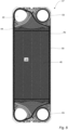
Fig. 3 is a plan view of a heat transfer plate according to the invention, -
Fig. 4 is a schematic side view of a portion of a plate pack comprised in the heat exchanger inFig. 1 , -
Fig. 5 is a plan view of a cassette according to the invention, and -
Fig. 6 is a highly schematic illustration of a portion of the heat transfer plate inFig. 3 . -
Figs. 1 and 2 show a semi-weldedplate heat exchanger 2 as described by way of introduction. It comprises aframe plate 4, apressure plate 6, a pack ofheat transfer plates 8, fluid inlets andoutlets 10, tightening means 12, anupper bar 14 and alower bar 16. - At least a majority of the
heat transfer plates 8, hereinafter also referred to as just "plates", are all similar. One of them, denoted 8a, is illustrated in further detail inFig. 3 . Theplate 8a is an essentially rectangular sheet of stainless steel. It comprises first and second opposinglong sides short sides plate 8a has a longitudinal center axis L extending parallel to, and halfway between, thelong sides short sides - The
plate 8a has a first side 30 (illustrated inFigs. 3 and4 ) and an opposing second side 32 (illustrated inFig. 4 ). Further, theplate 8a comprises anupper end part 34, a center part 36 and alower end part 38 arranged in succession along the longitudinal center axis L of theheat transfer plate 8a. Theupper end part 34 comprises afirst port hole 40, asecond port hole 42, a firstadiabatic area 39, a secondadiabatic area 41 and anupper distribution area 44. The center part 36 comprises aheat transfer area 46. Thelower end part 38 comprises athird port hole 48, afourth port hole 50, a thirdadiabatic area 49, a fourthadiabatic area 51 and alower distribution area 52. The first and third port holes 40 and 48 are arranged on one side of the longitudinal center axis L while the second and the fourth port holes 42 and 50 are arranged on the other side of the longitudinal center axis L. - The
heat transfer plate 8a is pressed, in a conventional manner, in a pressing tool, to be given a desired structure, such as different corrugation patterns within different portions of the heat transfer plate. The corrugation patterns are optimized for the specific functions of the respective plate portions. Accordingly, the upper andlower distribution areas heat transfer plate 8a. Further, theheat transfer area 46 comprises a heat transfer corrugation pattern adapted for optimized heat transfer between two fluids flowing on opposite sides of theheat transfer plate 8a. Furthermore, the first, second, third and fourthadiabatic areas plate 8a comprises anouter edge part 54 extending along anouter edge 56 of the plate. Theouter edge part 54 comprisescorrugations 58 extending in and between imaginary parallel first and second planes P1 and P2 (Fig. 4 ), which first plane P1 and second plane P2 face thefirst side 30 and thesecond side 32, respectively, of theplate 8a. Thesecorrugations 58 are arranged to abut corrugations of adjacent plates 8b and 8c in the plate pack of theplate heat exchanger 2. Similarly, with reference toFigs. 3 and4 , the heat transfer corrugation pattern comprises corrugations, more particularly alternately arrangedridges 60 andvalleys 62 as seen from thefirst side 30 of theplate 8a, extending in and between the first and second planes P1 and P2. Theseridges 60 andvalleys 62 are arranged to abut ridges and valleys of the adjacent plates 8b and 8c in the plate pack of theplate heat exchanger 2. Also the distribution corrugation pattern comprises corrugations arranged to abut corrugations of the adjacent plates in the plate pack of theplate heat exchanger 2. However, this is not further discussed herein. - Pressed into the
plate 8a, as seen from thefirst side 30 of the plate, is also a sealing groove 64 comprising a field sealing groove portion 64a, a first ring sealing groove portion 64b and a third ring sealing groove portion 64c. The sealing groove 64 is illustrated with lines inFig. 3 . The field sealing groove portion 64a encloses theheat transfer area 46 and the second and fourth port holes 42 and 50. A bottom 66a of the field sealing groove portion 64a extends in the second plane P2 (Fig. 4 ) along the complete length of the field sealing groove portion 64a. The first ring sealing groove portion 64b encloses thefirst port hole 40. A bottom 66b of the first ring sealing groove portion 64b extends in the second plane P2 along the complete length of the first ring sealing groove portion 64b. The third ring sealing groove portion 64c encloses thethird port hole 48. A bottom 66c of the third ring sealing groove portion 64c extends in the second plane P2 along the complete length of the third ring sealing groove portion 64c. - With reference to
Figs. 3 and5 , pressed into theplate 8a, as seen from thefirst side 30 of the plate, is also a gasket groove 68 for receiving a gasket 59 (comprising a field gasket portion and two ring gasket portions). The gasket groove 68 comprises a fieldgasket groove portion 68a, a second ring gasket groove portion 68b and a fourth ring gasket groove portion 68c. The fieldgasket groove portion 68a encloses theheat transfer area 46 and the first and third port holes 40 and 48. The fieldgasket groove portion 68a partly coincides with the field sealing groove portion 64a. Therefore, a bottom 70a of the fieldgasket groove portion 68a extends in the second plane P2 (Fig. 4 ) where the fieldgasket groove portion 68a coincides with the field sealing groove portion 64a. In fact, the bottom 70a of the fieldgasket groove portion 68a extends in the second plane P2 everywhere except for at twodiagonal sections 68a' of the fieldgasket groove portion 68a along which thebottom 70a extends between, here halfway between, the first plane P1 and the second plane P2. The second ring gasket groove portion 68b encloses thesecond port hole 42. A bottom 70b of the second ring gasket groove portion 68b extends between, here halfway between, the first plane P1 and the second plane P2 along the complete length of the second ring gasket groove portion 68b. The fourth ring gasket groove portion 68c encloses thefourth port hole 50. A bottom 70c of the fourth ring gasket groove portion 68c extends between, here halfway between, the first plane P1 and the second plane P2 along the complete length of the fourth ring gasket groove portion 68c. - In the plate pack of the
plate heat exchanger 2, theplates 8 are arranged with thefirst side 30 and thesecond side 32 of oneplate 8 facing the first side and the second side, respectively, of the neighboring heat transfer plates. Further, everysecond plate 8 is turned upside-down or rotated 180 degrees, in relation to a reference orientation, around a normal direction N which is normal to the figure plane ofFig. 3 . In other words, everysecond plate 8 is rotated 180 degrees around its transverse center axis.Fig. 4 illustrates the contact between thecorrugations 58 of the outer edge parts 54 (Fig.3 ) of theplate 8a and two adjacent plates 8b and 8c of the plate pack of theplate heat exchanger 2. - The
plates 8 of the plate pack are welded together in pairs,second side 32 tosecond side 32, along their respective sealing grooves 64, to formcassettes 57.Fig. 5 shows one of thecassettes 57 comprising theplate 8a illustrated inFig. 3 and the plate 8c visible inFig. 4 (but not inFig. 5 ). In the plate pack of theplate heat exchanger 2, the weldedcassettes 57 are separated bygaskets 59, at least a majority of which gaskets 59 are similar, one of thesegaskets 59 being illustrated inFig. 5 . In line with the above, thegaskets 59 are accommodated in the gasket grooves 68 of theplates 8, as is illustrated inFig. 5 . Thus, theheat exchanger 2 comprises channels of two different types; welded channels inside thecassettes 57 and gasketed channels between thecassettes 57. - Hereinafter, with reference to
Figs. 3 and6 , the first and second port holes 40 and 42 of theheat transfer plate 8a will be further described. The third and fourth port holes 48 and 50 are mirror inversions of the first and second port holes 40 and 42, respectively, and will not be separately described. - The
first port hole 40 is arranged within afirst portion 72 of theheat transfer plate 8a defined by the firstlong side 18, the firstshort side 22, the longitudinal center axis L and the transverse center axis T. Thefirst port hole 40 is illustrated, very schematically, inFig. 6 . It has a form defined by first, second and third corner points 74, 76 and 78, respectively, of an imaginary plane geometric figure 80 in the form of a triangle (dashed lines). Further, these corner points 74, 76 and 78 are connected by first, second and third thoroughlycurved lines first port hole 40. A reference point 88 of thefirst port hole 40 coincides with a center point C of a biggest imaginary circle 90 (ghost lines) that can be arranged in thefirst port hole 40. Thefirst corner point 74 is positioned closest to atransition 92 between the firstshort side 22 and the firstlong side 18 of theheat transfer plate 8a. Further, it is arranged on a first imaginarystraight line 94 extending from the reference point 88 and on a first distance d1 from the reference point 88. Thesecond corner point 76 is positioned closest to thefirst corner point 74 in the clockwise direction. Further, it is arranged on a second imaginarystraight line 96 extending from the reference point 88 and on a second distance d2 from the reference point 88. Thethird corner point 78 is positioned closest to thefirst corner point 74 in the counterclockwise direction. Further, it is arranged on a third imaginarystraight line 98 extending from the reference point 88 and on a third distance d3 from the reference point 88. - For the above first, second and third distances d1, d2 and d3 the following relationships are valid: d2 = d3 and d2 > d1. Further, a first angle α1 between the first and second imaginary
straight lines straight lines straight lines curved line 82 connecting the first and second corner points 74 and 76 is essentially uniform to the thirdcurved line 86 connecting the third and first corner points 78 and 74. In all, this means that thefirst port hole 40 is symmetric with a symmetry axis s extending through thefirst corner point 74 and the reference point 88. - As apparent from the figures and the description above, the
first port hole 40 has a non-circular form. More particularly, it has a form defined by a number of corner points, here three, of which at least one, here all, are displaced from anarc 100 of thecircle 90, and the same number of curved lines (here thus three) connecting these corner points. If thefirst port hole 40 was circular, it would preferably have a form corresponding to thecircle 90. From a pressure drop point of view, with reference to the previous discussions in this regard, an even largerfirst port hole 40 would be preferable. However, the design of the rest of theheat transfer plate 8a, limits the possible size of thefirst port hole 40. For example, a larger circularfirst port hole 40 would mean that a contour of the first port hole would be arranged closer to the firstshort side 22 and/or the firstlong side 18 which could result in strength problems of theheat transfer plate 8a. Further, with reference toFig. 5 , a larger circularfirst port hole 40 could also mean that the area between the first port hole and theupper distribution area 44 could be so narrow as to cause problems in pressing of the heat transfer plate with the above referenced corrugation patterns. Naturally, theupper distribution area 44 of theheat transfer plate 8a could be displaced further down on the heat transfer plate to make room for a largerfirst port hole 40. However, this would typically be associated with a smallerheat transfer area 46 and thus a worsened heat transfer capability of the heat transfer plate. - As described above and illustrated in the figures, the area of the
first port hole 40 can be increased without having to amend the design of the rest of the heat transfer plate. By letting thefirst port hole 40 occupy more of the first adiabatic area 39 (Fig. 3 ) of theheat transfer plate 8a than a circular first port hole with a form corresponding to thecircle 90 would do, a larger first port hole associated with a smaller pressure drop can be realized. Since it is the firstadiabatic area 39 only that is affected by this the enlargement, the distribution and heat transfer capability of theheat transfer plate 8a remains essentially unaffected. Further, since the contour of thefirst port hole 40 lacks straight portions, the bending stresses around the first port hole will be relatively low. - It should be stressed that a description corresponding to the one given above is valid also for the
third port hole 48 of theheat transfer plate 8a. - The
second port hole 42 is arranged within asecond portion 102 of theheat transfer plate 8a defined by the secondlong side 20, the firstshort side 22, the longitudinal center axis L and the transverse center axis T. Thesecond port hole 42 is circular. Thus, also thefourth port hole 50 is circular. - Since the
heat transfer plates 8 of theheat exchanger 2 comprises port holes of different forms, the ports of the heat exchanger will have different forms. More particularly, the ports for feeding a fluid into and out of the gasketed channels will have "rounded triangular" cross section which is advantageous as regards thermal performance, for instance concerning pressure drop and flow distribution inside the gasketed channels. Further, the ports for feeding a fluid into and out of the welded channels will have a circular cross section which is advantageous as regards mechanical strength. Thus, by designing the cassette with a circular port on the welded side and a non-circular port on the gasketed side, the cassette is pressure maximized for the welded side and thermally optimized for the gasketed side. - The above-described embodiment of the present invention should only be seen as an example. A person skilled in the art realizes that the embodiment discussed can be varied in a number of ways without deviating from the inventive conception.
- The heat transfer plate need not be rectangular but may have other shapes, such as circular or oval. The heat transfer plate need not comprise two non-circular portholes of rounded triangular form as described above but could instead comprise two non-circular portholes of another form. The corrugation patterns within the heat transfer area, distribution areas and adiabatic areas need not be designed as in the drawings.
- In the above-described embodiments, a majority of the plates and the gaskets between the cassettes are similar, but this is not mandatory. As an example, in a plate pack, plates of two or more different types may be combined.
- The bottom of the field gasket groove portion need not extend halfway between the first plane and the second plane at the two diagonal sections of the field gasket groove portion but may instead extend closer to one of the first and second planes. Similarly, the bottom of the second ring gasket groove portion, just like the bottom of the fourth ring gasket groove portion, need not extend halfway between the first plane and the second plane along their complete lengths but may instead, along part of their lengths or their complete lengths extend in another plane, for example closer to the first plane than the second plane. It should be stressed that the attributes front, back, upper, lower, first, second, third, etc. is used herein just to distinguish between details and not to express any kind of orientation or mutual order between the details.
- Further, it should be stressed that a description of details not relevant to the present invention has been omitted and that the figures are just schematic and not drawn according to scale. It should also be said that some of the figures have been more simplified than others. Therefore, some components may be illustrated in one figure but left out on another figure.
Claims (15)
- A heat transfer plate (8, 8a, 8b, 8c) comprising an upper end part (26), a center part (28) and a lower end part (30) arranged in succession along a longitudinal center axis (L) of the heat transfer plate (8, 8a, 8b, 8c), the upper end part (34) comprising a first port hole (40) and a second port hole (42) and the lower end part (38) comprising a third port hole (48) and a fourth port hole (50), the center part (36) comprising a heat transfer area (46) provided with a heat transfer corrugation pattern comprising ridges (60) and valleys (62) as seen from a first side (30) of the heat transfer plate (8, 8a, 8b, 8c), which ridges (60) and valleys (62) extend in and between imaginary parallel first and second planes (P1, P2), the first side (30) of the heat transfer plate (8, 8a, 8b, 8c) facing the first plane (P1) and an opposite second side (32) of the heat transfer plate (8, 8a, 8b, 8c) facing the second plane (P2), the heat transfer plate (8, 8a, 8b, 8c) further comprising, as seen from the first side (30), a sealing groove (64) comprising a field sealing groove portion (64a) enclosing the heat transfer area (46) and two of the first, second, third and fourth port holes (40, 42, 48, 50), the heat transfer plate (8, 8a, 8b, 8c) further comprising a gasket groove (68) comprising a field gasket groove portion (68a) enclosing the heat transfer area (46) and two of the first, second, third and fourth port holes (40, 42, 48, 50) which are not enclosed by the field sealing groove portion (64a), characterized in that the first port hole (40) and the third port hole (48) are non-circular and the second port hole (42), and the fourth port hole (50) are circular.
- A heat transfer plate (8, 8a, 8b, 8c) according to claim 1, wherein the first port hole (40) and the third port hole (48) are arranged on one side of the longitudinal center axis (L) of the heat transfer plate (8, 8a, 8b, 8c), and the second port hole (42) and the fourth port hole (50) are arranged on another side of the longitudinal center axis (L) of the heat transfer plate (8, 8a, 8b, 8c).
- A heat transfer plate (8, 8a, 8b, 8c) according to any of the preceding claims, wherein the field sealing groove portion (64a) encloses the second port hole (42) and the fourth port hole (50).
- A heat transfer plate (8, 8a, 8b, 8c) according to any of the preceding claims, wherein a bottom (66a) of the field sealing groove portion (64a), along at least more than half of a length of the field sealing groove portion (64a), extends in the second plane (P2).
- A heat transfer plate (8, 8a, 8b, 8c) according to any of the preceding claims, wherein the sealing groove (64) further comprises, as seen from the first side (30) of the heat transfer plate, a first ring sealing groove portion (64b) enclosing the first port hole (40) and a third ring sealing groove portion (64c) enclosing the third port hole (48), wherein a bottom (66b) of the first ring sealing groove portion (64b), along at least more than half of a length of the first ring sealing groove portion (64b), extends in the second plane (P2), and a bottom (66c) of the third ring sealing groove portion (64c), along at least more than half of a length of the third ring sealing groove portion (64c), extends in the second plane (P2).
- A heat transfer plate (8, 8a, 8b, 8c) according to any of the preceding claims, wherein the gasket groove (68) further comprises a second ring gasket groove portion (68b) enclosing the second port hole (42) and a fourth ring gasket groove portion (68c) enclosing the fourth port hole (50), wherein a bottom (70b) of the second ring gasket groove portion (68b), along at least more than half of a length of the second ring gasket groove portion (68b), extends between the first plane (P1) and the second plane (P2), and a bottom (70c) of the fourth ring gasket groove portion (68c), along at least more than half of a length of the fourth ring gasket groove portion (68c), extends between the first plane (P1) and the second plane (P2).
- A heat transfer plate (8, 8a, 8b, 8c) according to any of the preceding claims, wherein the first port hole (40) and the third port hole (48) each have only one symmetry axis (s).
- A heat transfer plate (8, 8a, 8b, 8c) according to any of claims 1-6, wherein the first port hole (40) is arranged within a first portion (72) of the heat transfer plate (8, 8a, 8b, 8c) defined by a first short side (22), a first long side (18), the longitudinal center axis (L) and a transverse center axis (T), of the heat transfer plate (8, 8a, 8b, 8c), and wherein a reference point (88) of the first port hole (40) coincides with a center point (C) of a biggest imaginary circle (90) that can be fitted into the first port hole (40), a form of the first port hole (40) being defined bya number of corner points (74, 76, 78) of an imaginary plane geometric figure (80) of which at least one is displaced from an arc (100) of the circle (90), andthe same number of curved lines (82, 84, 86) having no straight parts and connecting the corner points (74, 76, 78),wherein a first corner point (74) of the corner points (74, 76, 78) is arranged closest to a transition (92) between the first short side (22) and the first long side (18) and on a first distance (d1) from the reference point (88), a second one (76) of the corner points (74, 76, 78) is arranged closest to the first corner point (74) in a clockwise direction and on a second distance (d2) from the reference point (88) and a third one (78) of the corner points (74 76, 78) is arranged closest to the first corner point (74) in a counterclockwise direction and on a third distance (d3) from the reference point (88).
- A heat transfer plate (8, 8a, 8b, 8c) according to claim 8, wherein the first port hole (40) has one symmetry axis (s) only which extends through the first corner point (74) and the reference point (88).
- A heat transfer plate (8, 8a, 8b, 8c) according to any of claims 8-9, wherein the number of corner points (74, 76, 78) and curved lines (82, 84, 86) is equal to three.
- A heat transfer plate (8, 8a, 8b, 8c) according to any of claims 8-10, wherein the curved lines (82, 84, 86) are concave as seen from the reference point (88) of the first port hole (40).
- A heat transfer plate (8, 8a, 8b, 8c) according to any of claims 8-11, wherein the first distance (d1) between the first corner point (74) and the reference point (88) is smaller than the second distance (d2) between the second corner point (76) and the reference point (88).
- A heat exchanger plate (8, 8a, 8b, 8c) according to any of claims 8-12, wherein the first distance (d1) between the first corner point (74) and the reference point (88) is smaller than the third distance (d3) between the third corner point (78) and the reference point (88).
- A cassette (57) comprising two heat transfer plates (8, 8a, 8b, 8c) according to any of the preceding claims, wherein the second side (32) of one of the two heat transfer plates (8, 8a, 8b, 8c) faces the second side (32) of another one of the two heat transfer plates (8, 8a, 8b, 8c) and said another one of the two heat transfer plates (8, 8a, 8b, 8c) is rotated 180 degrees around a normal (N) of said another one of the two heat transfer plates (8, 8a, 8b, 8c), wherein the two heat transfer plates (8, 8a, 8b, 8c) are welded to each other along the sealing grooves (64).
- A heat exchanger (2) comprising a plurality of aligned cassettes (57) according to claim 14, further comprising gaskets (59) arranged in the gasket grooves (68) between each two adjacent ones of the cassettes (57).
Priority Applications (5)
| Application Number | Priority Date | Filing Date | Title |
|---|---|---|---|
| EP23204060.0A EP4542158A1 (en) | 2023-10-17 | 2023-10-17 | Heat transfer plate, cassette and heat exchanger |
| PCT/EP2024/077654 WO2025082740A1 (en) | 2023-10-17 | 2024-10-02 | Heat transfer plate and cassette |
| CN202480066161.2A CN122029395A (en) | 2023-10-17 | 2024-10-02 | Heat transfer plate and box |
| AU2024363285A AU2024363285A1 (en) | 2023-10-17 | 2024-10-02 | Heat transfer plate and cassette |
| TW113137743A TW202517953A (en) | 2023-10-17 | 2024-10-04 | Heat transfer plate and cassette |
Applications Claiming Priority (1)
| Application Number | Priority Date | Filing Date | Title |
|---|---|---|---|
| EP23204060.0A EP4542158A1 (en) | 2023-10-17 | 2023-10-17 | Heat transfer plate, cassette and heat exchanger |
Publications (1)
| Publication Number | Publication Date |
|---|---|
| EP4542158A1 true EP4542158A1 (en) | 2025-04-23 |
Family
ID=88416912
Family Applications (1)
| Application Number | Title | Priority Date | Filing Date |
|---|---|---|---|
| EP23204060.0A Withdrawn EP4542158A1 (en) | 2023-10-17 | 2023-10-17 | Heat transfer plate, cassette and heat exchanger |
Country Status (5)
| Country | Link |
|---|---|
| EP (1) | EP4542158A1 (en) |
| CN (1) | CN122029395A (en) |
| AU (1) | AU2024363285A1 (en) |
| TW (1) | TW202517953A (en) |
| WO (1) | WO2025082740A1 (en) |
Citations (6)
| Publication number | Priority date | Publication date | Assignee | Title |
|---|---|---|---|---|
| WO2001067021A1 (en) * | 2000-03-07 | 2001-09-13 | Alfa Laval Corporate Ab | Heat transfer plate and plate pack for use in a plate heat exchanger |
| WO2003006911A1 (en) * | 2001-07-09 | 2003-01-23 | Alfa Laval Corporate Ab | Heat transfer plate, plate pack and plate heat exchanger |
| WO2007142592A1 (en) * | 2006-06-05 | 2007-12-13 | Alfa Laval Corporate Ab | Plate and gasket for plate heat exchanger |
| WO2009082336A1 (en) | 2007-12-21 | 2009-07-02 | Alfa Laval Corporate Ab | Plate heat exchanger with guiding arrangement at the short ends |
| FR2967248A1 (en) * | 2010-11-10 | 2012-05-11 | Valeo Systemes Thermiques | HEAT EXCHANGER FLUID / FLUID |
| EP2728293A1 (en) * | 2012-10-30 | 2014-05-07 | Alfa Laval Corporate AB | Heat exchanger plate and plate heat exchanger comprising such a heat exchanger plate |
-
2023
- 2023-10-17 EP EP23204060.0A patent/EP4542158A1/en not_active Withdrawn
-
2024
- 2024-10-02 CN CN202480066161.2A patent/CN122029395A/en active Pending
- 2024-10-02 WO PCT/EP2024/077654 patent/WO2025082740A1/en active Pending
- 2024-10-02 AU AU2024363285A patent/AU2024363285A1/en active Pending
- 2024-10-04 TW TW113137743A patent/TW202517953A/en unknown
Patent Citations (6)
| Publication number | Priority date | Publication date | Assignee | Title |
|---|---|---|---|---|
| WO2001067021A1 (en) * | 2000-03-07 | 2001-09-13 | Alfa Laval Corporate Ab | Heat transfer plate and plate pack for use in a plate heat exchanger |
| WO2003006911A1 (en) * | 2001-07-09 | 2003-01-23 | Alfa Laval Corporate Ab | Heat transfer plate, plate pack and plate heat exchanger |
| WO2007142592A1 (en) * | 2006-06-05 | 2007-12-13 | Alfa Laval Corporate Ab | Plate and gasket for plate heat exchanger |
| WO2009082336A1 (en) | 2007-12-21 | 2009-07-02 | Alfa Laval Corporate Ab | Plate heat exchanger with guiding arrangement at the short ends |
| FR2967248A1 (en) * | 2010-11-10 | 2012-05-11 | Valeo Systemes Thermiques | HEAT EXCHANGER FLUID / FLUID |
| EP2728293A1 (en) * | 2012-10-30 | 2014-05-07 | Alfa Laval Corporate AB | Heat exchanger plate and plate heat exchanger comprising such a heat exchanger plate |
Also Published As
| Publication number | Publication date |
|---|---|
| AU2024363285A1 (en) | 2026-04-09 |
| WO2025082740A1 (en) | 2025-04-24 |
| TW202517953A (en) | 2025-05-01 |
| CN122029395A (en) | 2026-05-12 |
Similar Documents
| Publication | Publication Date | Title |
|---|---|---|
| EP2728293B1 (en) | Heat exchanger plate and plate heat exchanger comprising such a heat exchanger plate | |
| CN113424009A (en) | Heat exchanger | |
| EP4269925B1 (en) | Plate heat exchanger | |
| EP1405022B1 (en) | Heat transfer plate, plate pack and plate heat exchanger | |
| JP7152609B2 (en) | Heat transfer plates and cassettes for plate heat exchangers | |
| AU2022266963B2 (en) | Heat transfer plate and gasket | |
| EP3926282A1 (en) | Heat transfer plate, gasket and cassette | |
| WO2025082740A1 (en) | Heat transfer plate and cassette | |
| KR20260070224A (en) | Heat transfer plate and cassette | |
| CN112414181B (en) | Plate Heat Exchanger | |
| EP0853227A2 (en) | Heat exchanger | |
| EP4375605B1 (en) | Heat transfer plate | |
| EP4575369B1 (en) | Heat transfer plate, gasket arrangement, cassette and heat exchanger | |
| EP4675212A1 (en) | Plate set | |
| JP2022147760A (en) | Plate type heat exchanger | |
| EP4575368A1 (en) | Heat transfer plate, cassette and heat exchanger | |
| EP4215861B1 (en) | Heat exchanger construction | |
| EP4571235A1 (en) | Heat transfer plate, cassette and heat exchanger | |
| EP4343257A1 (en) | A plate heat exchanger | |
| CN113474613B (en) | Heat exchanger | |
| CN121816486A (en) | Heat exchanger plate and plate heat exchanger | |
| CN119895217A (en) | Heat exchanger | |
| CN119895219A (en) | Heat exchanger | |
| CN119907898A (en) | Heat Exchanger | |
| WO2022128387A1 (en) | Heat transfer plate |
Legal Events
| Date | Code | Title | Description |
|---|---|---|---|
| PUAI | Public reference made under article 153(3) epc to a published international application that has entered the european phase |
Free format text: ORIGINAL CODE: 0009012 |
|
| STAA | Information on the status of an ep patent application or granted ep patent |
Free format text: STATUS: THE APPLICATION HAS BEEN PUBLISHED |
|
| AK | Designated contracting states |
Kind code of ref document: A1 Designated state(s): AL AT BE BG CH CY CZ DE DK EE ES FI FR GB GR HR HU IE IS IT LI LT LU LV MC ME MK MT NL NO PL PT RO RS SE SI SK SM TR |
|
| STAA | Information on the status of an ep patent application or granted ep patent |
Free format text: STATUS: THE APPLICATION IS DEEMED TO BE WITHDRAWN |
|
| 18D | Application deemed to be withdrawn |
Effective date: 20251024 |