EP4542149A1 - Refrigerator - Google Patents
Refrigerator Download PDFInfo
- Publication number
- EP4542149A1 EP4542149A1 EP23827366.8A EP23827366A EP4542149A1 EP 4542149 A1 EP4542149 A1 EP 4542149A1 EP 23827366 A EP23827366 A EP 23827366A EP 4542149 A1 EP4542149 A1 EP 4542149A1
- Authority
- EP
- European Patent Office
- Prior art keywords
- lever
- door
- locking member
- refrigerator
- contact
- Prior art date
- Legal status (The legal status is an assumption and is not a legal conclusion. Google has not performed a legal analysis and makes no representation as to the accuracy of the status listed.)
- Pending
Links
Images







Classifications
-
- F—MECHANICAL ENGINEERING; LIGHTING; HEATING; WEAPONS; BLASTING
- F25—REFRIGERATION OR COOLING; COMBINED HEATING AND REFRIGERATION SYSTEMS; HEAT PUMP SYSTEMS; MANUFACTURE OR STORAGE OF ICE; LIQUEFACTION SOLIDIFICATION OF GASES
- F25D—REFRIGERATORS; COLD ROOMS; ICE-BOXES; COOLING OR FREEZING APPARATUS NOT OTHERWISE PROVIDED FOR
- F25D23/00—General constructional features
- F25D23/02—Doors; Covers
- F25D23/028—Details
-
- E—FIXED CONSTRUCTIONS
- E05—LOCKS; KEYS; WINDOW OR DOOR FITTINGS; SAFES
- E05D—HINGES OR SUSPENSION DEVICES FOR DOORS, WINDOWS OR WINGS
- E05D7/00—Hinges or pivots of special construction
- E05D7/08—Hinges or pivots of special construction for use in suspensions comprising two spigots placed at opposite edges of the wing, especially at the top and the bottom, e.g. trunnions
- E05D7/081—Hinges or pivots of special construction for use in suspensions comprising two spigots placed at opposite edges of the wing, especially at the top and the bottom, e.g. trunnions the pivot axis of the wing being situated near one edge of the wing, especially at the top and bottom, e.g. trunnions
-
- E—FIXED CONSTRUCTIONS
- E05—LOCKS; KEYS; WINDOW OR DOOR FITTINGS; SAFES
- E05F—DEVICES FOR MOVING WINGS INTO OPEN OR CLOSED POSITION; CHECKS FOR WINGS; WING FITTINGS NOT OTHERWISE PROVIDED FOR, CONCERNED WITH THE FUNCTIONING OF THE WING
- E05F1/00—Closers or openers for wings, not otherwise provided for in this subclass
- E05F1/08—Closers or openers for wings, not otherwise provided for in this subclass spring-actuated, e.g. for horizontally sliding wings
- E05F1/10—Closers or openers for wings, not otherwise provided for in this subclass spring-actuated, e.g. for horizontally sliding wings for swinging wings, e.g. counterbalance
- E05F1/12—Mechanisms in the shape of hinges or pivots, operated by springs
- E05F1/1207—Mechanisms in the shape of hinges or pivots, operated by springs with a coil spring parallel with the pivot axis
- E05F1/1215—Mechanisms in the shape of hinges or pivots, operated by springs with a coil spring parallel with the pivot axis with a canted-coil torsion spring
-
- E—FIXED CONSTRUCTIONS
- E05—LOCKS; KEYS; WINDOW OR DOOR FITTINGS; SAFES
- E05Y—INDEXING SCHEME ASSOCIATED WITH SUBCLASSES E05D AND E05F, RELATING TO CONSTRUCTION ELEMENTS, ELECTRIC CONTROL, POWER SUPPLY, POWER SIGNAL OR TRANSMISSION, USER INTERFACES, MOUNTING OR COUPLING, DETAILS, ACCESSORIES, AUXILIARY OPERATIONS NOT OTHERWISE PROVIDED FOR, APPLICATION THEREOF
- E05Y2201/00—Constructional elements; Accessories therefor
- E05Y2201/20—Brakes; Disengaging means; Holders; Stops; Valves; Accessories therefor
- E05Y2201/214—Disengaging means
-
- E—FIXED CONSTRUCTIONS
- E05—LOCKS; KEYS; WINDOW OR DOOR FITTINGS; SAFES
- E05Y—INDEXING SCHEME ASSOCIATED WITH SUBCLASSES E05D AND E05F, RELATING TO CONSTRUCTION ELEMENTS, ELECTRIC CONTROL, POWER SUPPLY, POWER SIGNAL OR TRANSMISSION, USER INTERFACES, MOUNTING OR COUPLING, DETAILS, ACCESSORIES, AUXILIARY OPERATIONS NOT OTHERWISE PROVIDED FOR, APPLICATION THEREOF
- E05Y2201/00—Constructional elements; Accessories therefor
- E05Y2201/20—Brakes; Disengaging means; Holders; Stops; Valves; Accessories therefor
- E05Y2201/218—Holders
- E05Y2201/22—Locks
-
- E—FIXED CONSTRUCTIONS
- E05—LOCKS; KEYS; WINDOW OR DOOR FITTINGS; SAFES
- E05Y—INDEXING SCHEME ASSOCIATED WITH SUBCLASSES E05D AND E05F, RELATING TO CONSTRUCTION ELEMENTS, ELECTRIC CONTROL, POWER SUPPLY, POWER SIGNAL OR TRANSMISSION, USER INTERFACES, MOUNTING OR COUPLING, DETAILS, ACCESSORIES, AUXILIARY OPERATIONS NOT OTHERWISE PROVIDED FOR, APPLICATION THEREOF
- E05Y2201/00—Constructional elements; Accessories therefor
- E05Y2201/20—Brakes; Disengaging means; Holders; Stops; Valves; Accessories therefor
- E05Y2201/23—Actuation thereof
- E05Y2201/232—Actuation thereof by automatically acting means
- E05Y2201/234—Actuation thereof by automatically acting means direction dependent
-
- E—FIXED CONSTRUCTIONS
- E05—LOCKS; KEYS; WINDOW OR DOOR FITTINGS; SAFES
- E05Y—INDEXING SCHEME ASSOCIATED WITH SUBCLASSES E05D AND E05F, RELATING TO CONSTRUCTION ELEMENTS, ELECTRIC CONTROL, POWER SUPPLY, POWER SIGNAL OR TRANSMISSION, USER INTERFACES, MOUNTING OR COUPLING, DETAILS, ACCESSORIES, AUXILIARY OPERATIONS NOT OTHERWISE PROVIDED FOR, APPLICATION THEREOF
- E05Y2201/00—Constructional elements; Accessories therefor
- E05Y2201/60—Suspension or transmission members; Accessories therefor
- E05Y2201/622—Suspension or transmission members elements
- E05Y2201/638—Cams; Ramps
-
- E—FIXED CONSTRUCTIONS
- E05—LOCKS; KEYS; WINDOW OR DOOR FITTINGS; SAFES
- E05Y—INDEXING SCHEME ASSOCIATED WITH SUBCLASSES E05D AND E05F, RELATING TO CONSTRUCTION ELEMENTS, ELECTRIC CONTROL, POWER SUPPLY, POWER SIGNAL OR TRANSMISSION, USER INTERFACES, MOUNTING OR COUPLING, DETAILS, ACCESSORIES, AUXILIARY OPERATIONS NOT OTHERWISE PROVIDED FOR, APPLICATION THEREOF
- E05Y2900/00—Application of doors, windows, wings or fittings thereof
- E05Y2900/30—Application of doors, windows, wings or fittings thereof for domestic appliances
- E05Y2900/31—Application of doors, windows, wings or fittings thereof for domestic appliances for refrigerators
-
- F—MECHANICAL ENGINEERING; LIGHTING; HEATING; WEAPONS; BLASTING
- F25—REFRIGERATION OR COOLING; COMBINED HEATING AND REFRIGERATION SYSTEMS; HEAT PUMP SYSTEMS; MANUFACTURE OR STORAGE OF ICE; LIQUEFACTION SOLIDIFICATION OF GASES
- F25D—REFRIGERATORS; COLD ROOMS; ICE-BOXES; COOLING OR FREEZING APPARATUS NOT OTHERWISE PROVIDED FOR
- F25D2323/00—General constructional features not provided for in other groups of this subclass
- F25D2323/02—Details of doors or covers not otherwise covered
- F25D2323/024—Door hinges
Definitions
- the present disclosure relates to a refrigerator.
- a refrigerator is a home appliance for storing food at a low temperature in a storage space that is covered by a refrigerator door.
- the refrigerator is configured to keep stored food in an optimal state by cooling the inside of the storage space using cold air generated through heat exchange with a refrigerant circulating in a refrigeration cycle.
- the refrigerator may be placed independently in a kitchen or a living room or may be accommodated in a kitchen cabinet.
- the refrigerator tends to increase in size more and more, and multi-functions are provided to the refrigerator as dietary life changes and pursues high quality, and accordingly, refrigerators of various structures in consideration of user convenience are, brought to the market.
- the refrigerator may include a cabinet defining a storage space and a door connected to the cabinet and having the storage space.
- a door storage portion for storing food may be provided in the door.
- the recent refrigerator is provided with a hinge device for automatically closing the door when the door is closed at a certain angle.
- An automatic return hinge device including a restoring device is disclosed in Korean Patent Registration No. 10-0874633 , which is a prior document.
- the hinge device may include a body, a clutch device mounted inside the body, a shaft coupled to pass through the clutch device, and a first spring that transmits restoring force to the shaft when the door is closed.
- the shaft serves to provide a rotational center of the door, and the first spring in the form of a coil spring is disposed in a direction parallel to the shaft.
- the restoration device since the restoration device is disposed in a direction parallel to the rotational center of the door, a space for positioning the restoration device as high as the height of the restoration device is required in the door, and thus, there is a restriction in installing the restoration device.
- the position of the rotational center of the door may vary according to a thickness of the door, and when the thickness of the door becomes thin, it may be impossible to install the restoration device in a direction parallel to the rotational center of the door.
- Embodiments provide a refrigerator in which a user operates an auto closing device by rotating a door at a minimum angle when the door reaches a reference angle during a closing process so that the user closes the door with little force.
- embodiments provide a refrigerator in which, when a user removes force for closing a door in a process of closing the door, an auto closing device does not operate to prevent a phenomenon, in which the door is maintained in an opened state, from occurring.
- embodiments provide a refrigerator provided with an auto closing device installed in a door regardless of a thickness of a door to provide closing force of the door.
- a refrigerator may include a cabinet having a storage space.
- the refrigerator may further include a hinge bracket coupled to the cabinet and having a contact surface.
- the refrigerator may further include a door rotatably coupled to a shaft provided in the hinge bracket and that opens or closes the storage space.
- the refrigerator may further include an auto closing device installed on the door at a position spaced apart from a rotation center C1 of the door, and that operates to automatically close the door by acting on the hinge bracket in a process of closing the door.
- the auto closing device may include a lever that rotates with respect to a rotation center C2 spaced apart from the rotation center C1 of the door.
- the auto closing device may further include an elastic member connected to the lever.
- the auto closing device may further include a locking member coupled to the lever to limit a rotation of the lever.
- the locking member is rotatable with respect to a rotation center C3 spaced apart from the rotation center C2 of the lever.
- the locking member may be coupled to the lever while an elastic force of the elastic member is accumulated or in the process of opening the door.
- the auto closing device may further include a body to rotatably support the lever.
- the elastic force of the elastic member When the door is closed, the elastic force of the elastic member may be a second elastic force. In a state in which a rotation of the lever is limited, the elastic force of the elastic member may be a first elastic force that is greater than the second elastic force. The door may be further opened while the rotation of the lever is restricted.
- the auto closing device may further include a housing coupled to the body or the door and that rotatably supports the locking member.
- the auto closing device may further include an elastic member that elastically supports the locking member within the housing.
- the lever may include a locking groove.
- the locking member may include a hook inserted into the locking groove. When the hook is inserted into the locking groove, a rotation of the lever may be restricted.
- the lever In the process of closing the door, the lever may move along the contact surface.
- the lever may include an extension portion configured to rotate the locking member in another direction while the lever is rotated in one direction with respect to the rotation center C2.
- the locking groove may be formed between the contact portion in contact with the contact surface and the extension portion in the lever.
- a distance from the rotation center C2 to an end of the extension portion may be less than a distance from the rotation center C2 to the contact portion of the lever in contact with the contact surface.
- the locking member may further include a receiving groove in which the extension portion is received in a locked state in which the rotation of the lever is restricted.
- the locking member may further include a contact protrusion that is pressed by the extension portion during a rotation of the lever in one direction.
- the receiving groove may be disposed between the rotation center C3 of the locking member and the contact protrusion.
- the auto closing device may further include a push member that pushes the lever or the locking member to unlock the lever with respect to the locking member during the process of closing the door.
- the push member pushes the lever so that the lever is rotated in one direction with respect to the rotation center C2, the locking member is rotated in another direction with respect to the rotation center C3 by the rotation of the lever in one direction, to unlock the lever.
- the contact surface may include a first surface. In the process of closing the door after the door is opened at an angle greater than a reference angle, the lever rotated by the push member may contact the first surface.
- the contact surface may further include a second surface extending to be inclined from the first surface.
- the contact surface may further include a third surface extending to be inclined from the second surface. In a state in which the door is closed, the lever may contact the third surface.
- the first surface may extend in a direction closer to the rotation center C1.
- the second surface may extend in a direction closer to the rotation center C1, and may have a different curvature from the first surface.
- the third surface may extend from the second surface in a direction away from a front surface of the cabinet. In the process of moving the lever from the first surface to the second surface, the lever may be spaced apart from the push member.
- the locking member may further include a rounded surface positioned between the hook and the contact protrusion.
- the extension portion may be in contact the rounded surface after passed the contact protrusion.
- the lever may include a rotatable roller.
- the push member may push the roller.
- the push member may be spaced apart from the contact surface in a horizontal direction. In the process of closing the door, the lever may pass through a space between the push member and the contact surface.
- the push member may be installed on the hinge bracket or the cabinet.
- a refrigerator may include a cabinet having a storage space.
- the refrigerator may include a hinge bracket coupled to the cabinet and having a contact surface.
- the refrigerator may include a door rotatably coupled to a shaft provided in the hinge bracket and that opens or closes the storage space.
- the refrigerator may further include a body installed on the door at a position spaced apart from a rotation center of the door.
- the refrigerator may further include a lever that is rotatably supported on the body and rotates with respect to a rotation center C2 spaced apart from a rotation center C1 of the door.
- the refrigerator may further include an elastic member connected to the lever.
- the refrigerator may further include a locking member rotatable with respect to a rotation center C3 spaced apart from the rotation center C2 of the lever and to limit a rotation of the lever.
- the refrigerator may further include a push member for releasing the locking of the lever by the locking member during the process of closing the door.
- the lever When the door is opened at an angle greater than a reference angle, the lever may be in a locked state in which rotation is restricted by the locking member while the elastic member accumulates elastic force. After the door is opened at an angle greater than the reference angle, the push member may push the lever or the locking member in the process of closing the door, thereby unlocking the lever.
- the elastic force accumulated in the elastic member may decrease.
- the elastic force of the elastic member acts as a closing force of the door, allowing the door to be closed.
- a refrigerator may include an auto closing device that operates to automatically close the door.
- the auto closing device may include a lever that rotates with respect to a rotation center C2 spaced apart from the rotation center C1 of the door.
- the auto closing device may include an elastic member connected to the lever.
- the auto closing device may further include a body installed on the door and that rotatably supports the lever.
- the auto closing device may further include a locking member rotatable with respect to a rotation center C3 spaced apart from the rotation center C2 of the lever. The locking member may be coupled to the lever and limit a rotation of the lever while the lever is rotated in a direction in which the elastic force of the elastic member increases during the opening of the door.
- the auto closing device may further include a housing coupled to the body or the door and that rotatably supports the locking member.
- the auto closing device may further include an elastic member that elastically supports the locking member within the housing.
- the lever may include a locking groove.
- the locking member may include a hook inserted into the locking groove. When the hook is inserted into the locking groove, a rotation of the lever may be restricted.
- the refrigerator may further include a hinge bracket that may contact the lever.
- the hinge bracket may include a contact surface that contacts the lever during the opening and closing process of the door.
- the lever rotates while the lever moves along the contact surface, and the locking member may rotate according to the rotation of the lever.
- the contact surface may include a first surface that contacts the lever when an opening angle of the door reaches a reference angle during the process of closing the door after the door is opened at an angle greater than the reference angle. While the lever moves along the first surface, the lever may be rotated in one direction with respect to the rotation center C2. The locking member may be rotated in one direction with respect the rotation center C3 by rotating the lever to unlock the lever.
- the contact surface may further include a second surface extending to be inclined from the first surface.
- the contact surface may further include a third surface extending to be inclined from the second surface and that contacts the lever in a state in which the door is closed.
- the first surface may extend in a direction away from the rotation center C1 of the door.
- the second surface may extend in a direction closer to the rotation center C1.
- the third surface may extend from the second surface in a direction away from a front surface of the cabinet.
- the lever may further include an extension portion for rotating the locking member while the lever is rotated in one direction with respect to the rotation center C2.
- the locking groove may be formed between the contact portion in contact with the contact surface in the lever and the extension portion.
- the locking member may include a receiving groove in which the extension portion is received in a locked state in which a rotation of the lever is restricted.
- the locking member may further include a contact protrusion that is pressed by the extension portion while the lever is rotated in one direction with respect to the rotation center C2. The contact protrusion may be located between the rotation center C3 and the receiving groove.
- the lever In the process of moving the lever from the first surface to the second surface, the lever is rotated in another direction with respect to the rotation center C2, and the locking member is also rotated in another direction with respect to the rotation center C3.
- the extension portion In the process of moving the lever from the first surface to the second surface, the extension portion may be received in the receiving groove of the locking member.
- the second surface may include a concave surface connected to the first surface.
- the second surface may further include a convex surface connected to the third surface.
- the lever In the process of moving the lever from the second surface to the third surface, the lever is rotated in another direction with respect to the rotation center C2, and the locking member is rotated in the one direction with respect to the rotation center C3.
- a refrigerator may include a cabinet having a storage space.
- the refrigerator may further include a hinge bracket coupled to the cabinet and having a contact surface.
- the refrigerator may further include a door rotatably coupled to a shaft provided in the hinge bracket and that opens or closes the storage space.
- the refrigerator may further include an auto closing device that is installed on the door at a position spaced apart from a rotation center of the door and operates to automatically close the door by acting on the hinge bracket during the process of closing the door.
- the auto closing device may include a lever that rotates with respect to a rotation center C2 spaced apart from the rotation center C1 of the door.
- the auto closing device may further include an elastic member connected to the lever.
- the auto closing device may further include a body installed on the door and that rotatably supports the lever.
- the auto closing device may further include a locking member rotatable with respect to a rotation center C3 spaced apart from the rotation center C2 of the lever.
- the locking member may unlock the lever by rotating in the same direction as the lever.
- a rotation angle of the lever when the lever is rotated in one direction may be different from a rotation angle when the locking member is rotated in one direction.
- a refrigerator may include an auto closing device that operates to automatically close the door by acting on a hinge bracket during the closing of the door.
- the auto closing device may include a lever that rotates with respect to a rotation center C2 spaced apart from the rotation center C1 of the door.
- the auto closing device may include an elastic member connected to the lever.
- the auto closing device may further include a locking member rotatable with respect to a rotation center C3 spaced apart from the rotation center C2 of the lever.
- an elastic force of the elastic member increases than a first elastic force and the locking of the lever by the locking member may be released. While the lever moves along another portion of the contact surface, the elastic force accumulated in the elastic member may decrease. In a section where the elastic force of the elastic member is decreased, the elastic force of the elastic member may act as a closing force of the door.
- the elastic force of the elastic member may be maintained as a second elastic force less than the first elastic force and greater than zero.
- the user when the user rotates the door at the minimum angle at a time point at which the door reaches a reference angle, since the auto closing device operates to automatically close the door, the user may close the door with the little force.
- the door In a state in which the lever is unlocked, since the lever receives the elastic force of the elastic member, the door may be automatically closed by the elastic force of the elastic member without manually closing the door by the user. Therefore, in the process of closing the door, when the user releases the door, a phenomenon in which the door is maintained in an opened state may be prevented from occurring.
- the auto closing device is disposed to be spaced apart from a rotational center line of the door, even when a thickness of the door is decreased, a closing force may be provided to the door while the door is closed.
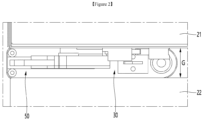
- FIG. 1 is a front view of a refrigerator according to a first embodiment of the present invention and FIG. 2 is an enlarged view illustrating a portion A of FIG. 1 .
- a refrigerator 1 may be installed independently in a kitchen or installed in an indoor furniture cabinet.
- the refrigerator 1 may be installed alone or arranged side by side with the other refrigerator.
- the refrigerator 1 may include a cabinet 10 having a storage space.
- the refrigerator 1 may include a refrigerator door 20 that opens or closes the storage space.
- the storage space may not be limited, but may be divided into an upper first space and a lower second space.
- the refrigerator door 20 may also include a first door 21 that opens and closes the first space and a second door 22 that opens and closes the second space.
- the first space may be a refrigerating compartment, and the second space may be a freezing compartment or vice versa.
- the storage space may include a first space and a second space, which are divided into left and right sides.
- the storage space may be a single space, and a single refrigerator door may open and close the storage space.
- At least one or more of the first door 21 and the second door 22 may be a rotation type door.
- the single refrigerator door 20 may be a rotation type door.
- the refrigerator door 20 may include an auto closing device 30 that provides a closing force to the refrigerator door 20 during the process of closing the refrigerator door 20.
- an auto closing device 30 is provided in the first door among the first and second doors arranged in the vertical direction. It should be noted that the position of the auto closing device 30 is not limited.
- a hinge bracket 50 is provided between the first door 21 and the second door 22.
- the hinge bracket 50 may be a common bracket that provides a rotational center of each of the first door 21 and the second door 22.
- the hinge bracket may be disposed at an upper side of the first door 21, and the hinge bracket may also be disposed at a lower side of the second door 22.
- the hinge bracket 50 may be fixed to a front surface of the cabinet 10.
- the hinge bracket 50 may include a shaft member 550 (to be described later).
- a gap G having a predetermined size may be defined between the first door 21 and the second door 22.
- a portion of the hinge bracket 50 is disposed between the first door 21 and the second door 22 so that the first door 21 and the second door 22 rotate without interfering with each other. At least a portion of the hinge bracket 50 may be spaced apart from a lower surface of the first door 21 as well as an upper surface of the second door 22.
- the auto closing device 30 may provide closing force to the first door 21 in a process of closing the first door 21 while acting with the hinge bracket 50.
- the auto closing device 30 is provided on the second door 22, it is also possible to provide closing force to the second door 22.
- the auto closing device 30 may be installed in the first door 21.
- the auto closing device 30 may be installed at a lower side of the first door 21.
- a portion of the auto closing device 30 may protrude downward from a lower surface of the first door 21.
- the auto closing device 30 may be installed at an upper side of the first door 21.
- the auto closing device 30 When the auto closing device 30 is installed at the lower side of the first door 21, the auto closing device 30 may not be well seen from the outside while the first door 21 is opened and closed.
- the auto closing device 30 may be spaced apart from an upper surface of the second door 22 so that the auto closing device 30 does not interfere with the second door 22.
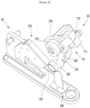
- FIG. 3 is perspective view illustrating relative positions of a hinge bracket and an auto closing device in a state in which the door is closed
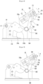
- FIG. 4 is a perspective view showing relative positions of a hinge bracket and an auto closing device in a state in which the door is opened at a reference angle
- FIG. 5 is an exploded perspective view of an auto closing device.
- FIG. 6 is a bottom view of an auto closing device and a hinge bracket showing relative positions of the hinge bracket and the auto closing device in a state in which the door is opened at a reference angle.
- the hinge bracket 50 may include a coupling portion 510 to be coupled to the cabinet 10.
- the hinge bracket 50 may further include a bracket body 520 extending in a horizontal direction from the coupling portion 510.
- the coupling portion 510 may include one or more coupling holes 512.
- a coupling member may be coupled to the cabinet 10 through the coupling hole 512.
- a shaft member 550 may be coupled to the bracket body 520.
- the shaft member 550 may include a first shaft 554 that provides a rotation center of the first door 21.
- the shaft member 550 may further include a second shaft 556 that provides a rotation center of the second door 22.
- the second shaft 556 can be omitted.
- the shaft member 550 may further include a seating portion 552 seated on the bracket body 520.
- the first shaft 554 may extend upward from the seating portion 552.
- the second shaft 556 may extend downward from the seating portion 552.
- a diameter of the seating portion 552 may be greater than a diameter of the second shaft 556.
- a hole (not shown) through which the second shaft 556 passes may be formed in the bracket body 520.
- the first door 21 may be coupled to the first shaft 554.
- the second door 22 may be coupled to the second shaft 556.
- the hinge bracket 50 may further include a cam member 570 that is detachably coupled to the bracket body 520.
- the cam member 570 may include a contact surface 576 for contacting the lever 320. When the contact surface 576 is worn, the cam member 570 may be separated from the bracket body 520 and then a new cam member 570 may be coupled to the bracket body 520. When the cam member 570 is detachably coupled to the bracket body 520, only the cam member 570 may be replaced without replacing the entire hinge bracket 50 and there is an advantage of reducing service costs.
- the cam member 570 Since the cam member 570 is detachably coupled to the bracket body 520, the cam member 570 may be separated while the first door 21 and the second door 22 are opened. Therefore, it has an advantage of being easy to service. That is, since there is no need to separate the doors, there is an advantage that the cam member may be easily replaced.
- the cam member 570 it is also possible for the cam member 570 to be formed integrally with the bracket body 520. In this case, the bracket body 520 may include a contact surface 576.
- the cam member 570 may include a first cam body 572 and a second cam body 573 coupled to the first cam body 572.
- the first cam body 572 and the second cam body 573 may be coupled by a coupling member via the bracket body 520.
- the first cam body 572 is coupled to the second cam body 573.
- the first cam body 572 may include one or more coupling holes 574.
- the second cam body 573 may include one or more coupling holes 575. A coupling hole aligned with each of the coupling holes 574 and 575 may also be formed in the bracket body 520.
- a portion of the first cam body 572 may provide a portion of the contact surface 576, and a portion of the second cam body 573 may provide another portion of the contact surface 576. Alternatively, it is possible for only one of the first cam body 572 and the second cam body 573 to provide the contact surface 576.
- the auto closing device 30 may be disposed at a position spaced apart from the first shaft 554 in the horizontal direction. That is, the auto closing device 30 may be coupled to the first door 21 at a position spaced apart from the first shaft 554. The auto closing device 30 may rotate together with the first door 21 and the auto closing device 30 may interact with the bracket body 520 in a process of closing the first door 21 to provide the closing force to the first door 21.
- the auto closing device 30 may include a body 310.
- the auto closing device 30 may further include a lever 320 rotatably coupled to the body 310.
- the auto closing device 30 may further include an elastic member 350 connected to the lever 320.
- the body 310 may define an outer appearance of the auto closing device 30.
- the lever 320 may be rotated in a horizontal direction with respect to the rotation center (C2: see FIG. 6 ). That is, a line passing through the rotation center of the first door 21 (C1: see Figure 6 ) and a line passing through the rotation center of the lever 320 (C2: see Figure 6 ) are parallel and may be spaced apart in the horizontal direction.
- the body 310 may receive a portion of the lever 320.
- the body 310 may include a first body 311 that receives a portion of the lever 320.
- the first body 311 may be provided with a slot 312 for insertion of the lever 320.
- the lever 320 In a state in which the lever 320 is inserted into the first body 311, the lever 320 may be rotated. Accordingly, the slot 312 may extend in a circumferential direction of the first body 311 to enable rotation of the lever 320.
- the body 310 may further include a second body 313 located above the first body 311.
- the second body 313 may be coupled to the first door 21.
- the second body 313 may be formed integrally with the first body 311 or may be coupled to the first body 311.
- the first body 311 may be formed in a cylindrical shape.
- the second body 313 may be formed in a rectangular parallelepiped shape.
- One or more coupling holes 314 may be formed in the second body 313.
- Each of the first body 311 and the second body 313 may include an opening penetrating in a vertical direction. The opening of the first body 311 may communicate with the opening of the second body 313.
- the body 310 may further include a third body 317 located above the second body 313.
- the third body 317 may be coupled to an upper side of the second body 313.
- the auto closing device 30 may further include a first connector 340 disposed within the body 310.
- the first connector 340 may be connected to the lever 320 inserted into the body 310.
- the first connector 340 may be connected to the lever 320 and rotated together with the lever 320.
- the first connector 340 may be received in the body 310 from an upper side of the body and coupled to the lever 310 in a state in which the lever 320 is inserted into the body 310 through the slot 312. A portion of the first connector 340 may pass through the lever 320 and be coupled to the lever 320.
- the first connector 340 may connect the elastic member 350 to the lever 320.
- the first connector 340 may include a lever coupling portion 341a.
- the lever coupling portion 341a may be coupled to the lever 320.
- the first connector 340 may include a first elastic member coupling portion 341b coupled to the elastic member 350.
- the first connector 340 may further include a partition plate 342 disposed between the lever coupling portion 341a and the first elastic member coupling portion 341b. Based on the partition plate 342, the lever coupling portion 341a may be provided at a lower side of the partition plate 342, and the first elastic member coupling portion 341b may be provided at an upper side of the partition plate 342.
- the lever coupling portion 341a may include a first rib and a second rib spaced apart in the horizontal direction. A first coupling space may be formed between the first rib and the second rib. As another example, the lever coupling portion 341a may be formed in a single rib shape or may be formed in a non-circular shape.
- the lever 320 may include a plurality of rib holes through which the first and second ribs respectively pass. The plurality of rib holes may be spaced apart from each other. When the lever coupling portion 341a includes one rib, the lever 320 may also include one rib hole of a shape corresponding to the rib.
- the first elastic member coupling portion 341b may include a third rib and a fourth rib spaced apart in the horizontal direction.
- a second coupling space may be formed between the third rib and the fourth rib.
- a portion of the elastic member 350 may be received in the coupling space.
- the lever 320 may include a first portion 321 coupled to the first connector 340.
- the first portion 321 may also be referred to as a connector coupling portion.
- a portion of the first portion 321 may pass through the slot 312 and be received in the body 310.
- Another portion of the first portion 321 may be located at the body 310.
- the rib hole may be formed in the first portion 321.
- the lever 320 may further include a second portion 322 extending from the first portion 321 in a horizontal direction.
- the second portion 322 may extend while maintaining the same height as the first portion 321.
- the lever 320 may further include a contact portion for contacting the bracket body 520.
- the contact portion may be a roller 327.
- the roller 327 may be rotatably coupled to the second portion 322 by a roller pin 326.
- the roller 327 may be disposed at lower side of the second portion 322.
- the lever 320 may further include a third portion 324 extending from the first portion 321 in a direction different from an extending direction of the second portion 322.
- the third portion 324 may function with a locking member 70, which will be described later.
- the third portion 324 may be referred to as an extension portion.
- the elastic member 350 may be, for example, a torsion spring.
- the elastic member 350 may include a body portion 352 provided by winding a wire multiple times.
- the body portion 352 may have a cylindrical or truncated cone shape.
- the elastic member 350 may include a first extension portion 354 extending in the horizontal direction from a lower end of the body portion 352.
- the first extension portion 354 may extend toward a center of the body portion 352.
- the first extension portion 354 may be coupled to the first connector 340.
- the first extension portion 354 may be inserted into the second coupling space 348 of the first elastic member coupling portion 341b.
- the first elastic member coupling portion 341b may be received into the body portion 352.
- the first extension portion 354 and the body portion 352 may be seated on the partition plate 342.
- the elastic member 350 may further include a second extension portion 356 extending in the horizontal direction from an upper end of the body portion 352.
- the auto closing device 30 may further include a second connector 360 coupled to the elastic member 350.
- the second extension portion 356 may be coupled to the second connector 360.
- the second connector 360 may include a second elastic member coupling portion 361a.
- the second connector 360 may further include a pin coupling portion 361b.
- the second connector 360 may further include a partition plate 362 disposed between the second elastic member coupling portion 361a and the pin coupling portion 361b. Based on the partition plate 362, the pin coupling portion 361b may be provided at an upper side of the partition plate 342.
- the second elastic member coupling portion 361a may be provided at a lower side of the partition plate 362.
- pin coupling portion 361b may be the same or similar to that of the second elastic member coupling portion 361a, detailed description will be omitted.
- the auto closing device 30 may further include an upper cap 370 to cover an upper opening of the body 310.
- the upper cap 374 may include a cap body 372 having a hollow 373 therein.
- the upper cap 374 may further include a flange 374 extending from an upper end of the cap body 372 in the horizontal direction.
- the upper cap 370 can be omitted.
- the cap body 372 may be inserted into the body 310.
- the flange 374 may be seated on an upper surface of the body 310.
- the pin coupling portion 361b may be inserted into the hollow 373.
- the auto closing device 30 may further include a fixing pin 380.
- the fixing pin 380 may limit a rotation of the second connector 360.
- the fixing pin 380 may fix the upper cap 370 to the body 310.
- a pair of first pin holes 318 through which the fixing pin 380 passes may be formed in the body 310.
- a pair of second pin holes 375 through which the fixing pin 380 passes may be formed in the cap body 372.
- the fixing pin 380 may be inserted into the pin coupling portion 361b. That is, after passing through one first pin hole 318 and one second pin hole 375, the fixing pin 380 may pass through the pin coupling portion 361b and pass through the other second pin hole 375 and the other first pin hole 318.
- the positions of the upper cap 370 and the second connector 360 may be fixed to the body 310 by the fixing pin 380. That is, rotation of the upper cap 370 and the second connector 360 may be restricted by the fixing pin 380.
- the second extension portion 356 of the elastic member 350 is a fixed end, and the first extension portion 354 is a movable end.
- the first extension portion 354 is rotatable together with the lever 320.
- the elastic member 350 When the first extension portion 354 of the elastic member 350 rotates in one direction while the second extension portion 356 is fixed, the elastic member 350 accumulates the elastic force.
- the elastic force accumulated by the elastic member 350 may act as the lever 320 so that the lever 320 rotates in another direction opposite to the one direction. In this manner, the elastic force accumulated by the elastic member 350 substantially acts on the first door 21 in the process of closing the first door 21 so that the first door 21 is automatically closed at a predetermined position.
- the auto closing device 30 may further include a locking unit 70.
- the locking unit 70 may limit a rotation of the lever 320 when the first door 21 is opened at an angle equal to or greater than a predetermined angle.
- the elastic force of the elastic member 350 may be accumulated, and in the process of increasing the elastic force of the elastic member 350, when the first door 21 may be opened at the predetermined angle, the locking unit 70 may be connected to the lever 320 to limit the rotation of the lever 320.
- the locking unit 70 may include a locking member 730 that is rotatable with respect to the lever 320.
- the locking member 730 may be rotated independently of the lever 320.
- the locking member 730 may be coupled to or disengaged from the lever 320.
- the locking unit 70 may further include a housing 710 to which the locking member 730 is rotatably connected.
- the housing 710 may include a hollow 715 extending in a vertical direction.
- the housing 710 may receive a portion of the locking member 730.
- the housing 710 may include a first housing 711.
- the locking member 730 may be received in the first housing 711.
- the first housing 711 may be provided with a slot 717 for insertion of the locking member 730.
- a portion of the locking member 730 that passed the slot 717 may be located in the hollow 715.
- the locking member 730 When the locking member 730 is inserted into the first housing 711, the locking member 730 may be rotated with respect to the first housing 711. Accordingly, the slot 717 may extend in a circumferential direction of the first housing 711 to enable rotation of the locking member 730.
- the housing 710 may further include a second housing 712 located above the first housing 711.
- the second housing 712 may be coupled to the first door 21 or the body 310.
- the second housing 712 is coupled to the body 310 as an example.
- the second housing 712 may include a coupling extension portion 713 extending in the horizontal direction.
- the coupling extension portion 713 may contact the body 310.
- the coupling extension portion 713 may contact an upper surface or a lower surface of the second body 313.
- a seating groove 315 for seating the coupling extension portion 713 may be recessed and formed on the upper surface of the second body 313.
- a first coupling hole 316 may be formed in the seating groove 315.
- a second coupling hole 714 aligned with the first coupling hole 316 may also be formed in the coupling extension portion 713. Accordingly, the housing 710 may be coupled to the body 310 as the coupling member passes through the coupling holes 316 and 714. It is also possible for a coupling member passing through the coupling hole 316 and 714 to be coupled to the first door.
- the locking unit 70 may further include a locking member connector 720 disposed within the housing 710.
- the locking member connector 720 may be connected to the locking member 730 inserted into the housing 710.
- the locking member connector 720 may be connected to the locking member 730 and may rotate together with the locking member 730.
- the locking member connector 720 may be received in the housing 710 from an upper side of the housing 710 and coupled to the locking member 730 in a state in which the locking member 730 is inserted into the housing 710 through the slot 717.
- a portion of the locking member connector 720 may pass through the locking member 730 and be coupled to the locking member 730.
- the locking member connector 720 may be connected to an elastic member 750, which will be described later.
- the locking member connector 720 may include a lever coupling portion 720a and an elastic member coupling portion 720b.
- the locking member 730 may include one or more rib holes 732 into which one or more ribs of the lever coupling portion 720a are inserted.
- the locking unit 70 may further include an elastic member 750.
- the elastic member 750 may be received within the housing 710. A portion of the elastic member 750 may be received in the coupling space of the elastic member coupling portion 720b.
- the elastic member 750 may be a torsion spring, for example. Since a basic structure of the elastic member 750 may be the same or similar to that of the elastic member 350 received in the body 310, detailed description will be omitted.
- the locking unit 70 may further include an elastic member connector 760 coupled to the elastic member 750. Since a basic structure of the elastic member connector 760 of this embodiment may be the same or similar to that of the second connector 360, detailed description will be omitted.
- the locking unit 70 may further include a fixing pin 780 for fixing the elastic member connector 760 to the housing 710.
- a hole 716 may be formed in the housing 710 through which the fixing pin 780 passes.
- the fixing pin 780 may be coupled to the elastic member connector 760 after passing through the pin hole 716.
- a hook 734 may be provided at an end of the locking member 730.
- a locking groove 323 into which the hook 734 is inserted may be formed in the lever 320. When the hook 734 is inserted into the locking groove 323, the rotation of the lever 320 may be restricted by the locking member 730.
- the locking member 730 may include a contact protrusion 735.
- the contact protrusion 735 may contact the lever 320.
- the contact protrusion 735 may be in contact with the third portion 324 of the lever 320.
- the contact protrusion 735 may be located in a portion of the locking member 730 where the locking member coupling portion 720a is coupled or between a rotation center C3 of the locking member 730 and the hook 734.
- the locking member 730 may further include a receiving groove 737 for receiving a portion of the lever 320 when the rotation of the lever 320 is restricted.
- the third portion 324 may be received in the receiving groove 737.
- the receiving groove 737 may be located between the contact protrusion 735 and the rotation center C3 of the locking member 730.
- the third portion 324 may be located on an opposite side of the roller 327 (which is a contact portion of the lever) with respect to the locking groove 323. That is, the locking groove 323 may be disposed between the third portion 324 and the roller 327. A distance from the rotation center C2 to an end of the third portion 324 may be less than a distance from the rotation center C2 to the roller 327 (which is the contact portion of the lever).
- the contact protrusion 735 may protrude in the horizontal direction from a side surface 736 of the locking member 730.
- the first door 21 may further include a push member 540 that operates to release the locked state of the lever 320 during the process of closing the first door 21.
- the push member 540 may push the lever 320 in the process of closing the first door 21.
- the push member 540 may be installed on the hinge bracket 50 or on the cabinet 10.
- FIG. 3 shows the push member 540 being installed on the coupling portion 510 of the hinge bracket 50.
- the push member 540 may include a coupling body 542 coupled to the coupling portion 510.
- a coupling hole 543 through which a coupling member for coupling to the coupling portion 510 passes may be formed in the coupling body 542.
- the push member 540 may further include a push body 544 extending from the coupling body 542.
- the push body 544 may extend from the coupling body 542 in the horizontal direction.
- the push body 544 may be positioned at the same height as at least a portion of the lever 320. Therefore, in the process of closing the lever 320, the lever 320 may contact the push body 544.
- the push body 544 may be positioned at the same height as the roller 327 of the lever 320.
- the contact surface 576 may also be disposed at the same height as the roller 327.
- the push body 544 may be arranged to be spaced apart from the contact surface 576 in the horizontal direction.
- the roller 327 may be disposed in a space between the contact surface 576 and the push body 544.
- the push body 544 may include a push surface 545 with which the roller 327 comes into contact.
- the push surface 545 may be an inclined surface or a rounded surface.
- the roller 327 In the process of closing the first door 21, the roller 327 may be pushed while moving along the push surface 545. In the process of moving the roller 327 along the push surface 545, the roller 327 may be pressed and the lever 320 may be rotated.
- the contact surface 576 may include a first surface 576a that the lever 320 initially contacts during the process of closing the first door 21.
- the lever 320 may not be in contact with the first surface 576a.
- the lever 320 may contact the first surface 576a.
- At least a portion of the first surface 576a may be a concave surface.
- the contact surface 576 may further include a second surface 576b extending from the first surface 576a.
- the second surface 576b may be disposed to be inclined with respect to the first surface 576a.
- a curvature of the second surface 576b may be greater than a curvature of the first surface 576a.
- the contact surface 576 may further include a third surface 576c extending from the second surface 576b.
- the third surface 576c may be disposed to be inclined with respect to the second surface 576b.
- the first surface 576a may be inclined in a direction close to an imaginary line A1 perpendicular to the coupling portion 510 and passing through the rotation center C1 of the first door 21.
- the first surface 576a may extend in a direction away from the rotation center C1.
- the third surface 576c may extend in a direction closer to the imaginary line A1 as a distance from the coupling portion 510 increases.
- the third surface 576c may extend from the second surface 576b in a direction away from the coupling portion 510 (or the front surface of the cabinet 10).
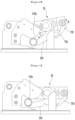
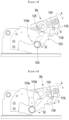
- FIG. 7 is a bottom view of an auto closing device and a hinge bracket showing relative positions of the hinge bracket and the auto closing device in a state in which the door is opened by a first angle less than the reference angle
- FIG. 8 is a bottom view of an auto closing device and a hinge bracket showing elative positions of the hinge bracket and the auto closing device in a state in which the door is opened by a second angle less than the first angle.
- FIG. 9 is a bottom view of an auto closing device and a hinge bracket showing relative positions of the hinge bracket and the auto closing device in a state in which the door is opened by a third angle less than the second angle
- FIG. 10 is a bottom view of an auto closing device and a hinge bracket showing relative positions of the hinge bracket and the auto closing device in a state in which the door is opened by a fourth angle less than the third angle.
- FIG. 11 is a bottom view of an auto closing device and a hinge bracket showing relative positions of the hinge bracket and the auto closing device when the door is closed.
- the third portion 324 of the lever 320 may be in contact with the locking member 730 and an end of the lever may be received in the receiving groove 737.
- a distance from the rotation center C2 of the lever 320 to the receiving groove 737 may be greater than a distance from the rotation center C2 of the lever 320 to the contact protrusion 735.
- the locking member 730 receives elastic force from the elastic member 750, unless an external force is applied to the lever 320 or the locking member 730, an insertion of the hook 734 of the locking member 730 into the locking groove 323 of the lever 320 may be maintained.
- a state in which the hook 734 is inserted into the locking groove 323 may be referred to as a locking state of the lever 320.
- a state in which the hook 734 is removed from the locking groove 323 may be referred to as an unlocked state of the lever 320.
- a direction in which the locking member 730 is rotated to insert the hook 734 into the locking groove 323 may be referred to as a locking direction.
- a direction in which the locking member 730 is rotated to remove the hook 734 from the locking groove 323 may be referred to as an unlocking direction.
- the lever 320 may contact the push surface 545 of the push body 544.
- the lever 320 may contact the first surface 576a.
- the lever 320 in the process of further rotating the first door 21 in THE A direction in a state in which the lever 320 is in contact with the push surface 545, the lever 320 may be pushed by the push surface 545. Then, the lever 320 may be rotated in a C direction (for example, clockwise direction based on FIG. 7 ) with respect to the rotation center C2.
- a C direction for example, clockwise direction based on FIG. 7
- the end of the third portion 324 presses the contact protrusion 735 of the locking member 730.
- the locking member 730 rotates in a B direction (for example, clockwise or unlocking direction based on FIG. 7 ) with respect to the rotation center C3. That is, the locking member 730 rotates in a direction opposite to the rotation direction of the lever 320.
- the third portion 324 serves to transmit the rotational force of the lever 320 to the locking member 730.
- the hook 734 gets out of the locking groove 323.
- the hook 734 may get out of the locking groove 323 in a state in which the opening angle of the first door 21 is a first angle less than the reference angle.
- the lever 320 may move along the first surface 576a while maintaining contact with the first surface 576a.
- the lever 320 Since the locked state of the lever 320 is released at the position shown in FIG. 7 , the lever 320 may be rotated in the C direction by the elastic force of the elastic member 350. In this state, even if the user does not provide closing force to the first door 21, the first door 21 can be automatically closed by the auto closing device 30.
- the lever 320 when the first door 21 is further rotated in the A direction, the lever 320 may be spaced apart from the push surface 545. Since the lever 320 receives the elastic force of the elastic member 350, the lever 320 can move along the first surface 576a to the second surface 576c.
- the third portion 324 gets out of the receiving groove 737 and may be in contact with the side surface 736 of the locking member 730.
- At least a portion of the side surface 736 may be a rounded surface that is rounded in a direction away from the rotation center C2.
- the lever 320 may continuously rotate in the C direction and move along the second surface 376b due to the elastic force of the elastic member 350.
- the elastic force of the elastic member 350 decreases as a cumulative rotation angle (during closing process) in the C direction of the lever 320 increases.
- the decreasing elastic force of the elastic member 350 acts as a closing force of the first door 21.
- the locking member 730 may be continuously rotated in the unlocking direction, or the rotation of the locking member 730 may be stopped just before the first door 21 is closed, or the locking member 730 may be rotated in the locking direction just before the first door 21 is closed.
- the lever 320 may substantially rotates at a predetermined angle with respect to the body 310, and thus, the elastic member 350 may be maintained to accumulate a second elastic force having a predetermined intensity.
- the second elastic force is less than the first elastic force but greater than zero.
- the elastic member 350 applies force in the direction in which the first door 21 is closed in the state in which the first door 21 is closed, the closed state of the first door 21 may be stably maintained.
- the lever 320 in a state in which the first door 21 is opened at an angle equal to or greater than the reference angle, the lever 320 may be in the locked state in a state in which the elastic member 350 accumulates the first elastic force.
- the locking of the lever 320 may be released.
- the difference between the reference angle and the first angle is not limited, but may be about 5 degrees or less.
- the first door 21 may be automatically closed by the elastic force of the elastic member 350 even if the user does not manually close the first door 21.
- the first door 21 may be prevented from being maintained in the opened state.
- the lever 320 When the first door 21 is opened while the first door 21 is closed, the lever 320 may rotate in a counterclockwise direction with respect to the body 310. When the lever 320 rotates in the counterclockwise direction with respect to the body 310, the elastic force of the elastic member 350 may increase from the second elastic force. When the opening angle of the first door 21 increases, the rotational angle of the lever 320 increases, and the elastic force of the elastic member 350 may continuously increase.
- the locking member 730 rotates in the locking direction (clockwise direction in the drawing).
- the lever 320 comes into contact with the push surface 545, and the third portion 324 may be received in the receiving groove 737 after passed the contact protrusion 735.
- the hook 734 is located adjacent to the locking groove 323.
- the hook 734 may be inserted into the locking groove 323.
- the hook 734 is inserted into the locking groove 323, and the elastic force of the elastic member 350 is accumulated as the first elastic force, and the rotation of the lever 320 may be restricted.
- the push member 540 pushes the lever 320 during the closing process of the first door 21.
- the push member 540 may push the locking member 730.
- the locking member 730 may be provided with an extension portion, and during the process of closing the first door 21, the push member 540 pushes the extension portion so that the locking member 730 may be rotated in the unlocking direction.
- FIG. 12 is a perspective view showing relative positions of a hinge bracket and an auto closing device in a state in which the door is closed according to a second embodiment of the present invention
- FIG. 13 is a perspective view showing relative positions of a hinge bracket and an auto closing device in a state in which the door is opened at a reference angle according to a second embodiment
- FIG. 14 is an exploded perspective view of an auto closing device according to a second embodiment.
- FIG. 15 is a bottom view of an auto closing device and a hinge bracket showing relative positions of the hinge bracket and the auto closing device in a state in which the door is opened at a reference angle according to a second embodiment.
- the refrigerator of this embodiment may include a hinge bracket 1500 and an auto closing device 30a.
- the hinge bracket 1500 of this embodiment may include a coupling portion 1510 for being coupled to the cabinet 10, and a bracket body 1520 extending from the coupling portion 1510 in a horizontal direction.
- the hinge bracket 1500 may further include a shaft member 1550.
- hinge bracket 1500 of this embodiment is the same or similar to the hinge bracket of the first embodiment, a detailed description will be omitted.
- the hinge bracket 1500 may further include a cam member 1570 detachably coupled to the bracket body 1520.
- the cam member 1570 may include a contact surface 1576 for contacting the lever 320.
- a basic structure of the cam member 1570 may be the same as the cam member of the first embodiment.
- the cam member 1570 may include a first cam body 1572 and a second cam body 1573 coupled to the first cam body 1572.
- the first cam body 1572 and the second cam body 1573 may be coupled by a coupling member via the bracket body 1520.
- the auto closing device 30a of this embodiment may include a body 310.
- the auto closing device 30a may further include a lever 1320 rotatably coupled to the body 310.
- the auto closing device 30a may further include an elastic member 350 connected to the lever 1320.
- the body 310 of this embodiment may be the same as the body of the first embodiment.
- the auto closing device 30a may further include a first connector 340 disposed within the body 310.
- the first connector 340 may be connected to the lever 1320 inserted into the body 310.
- the first connector 340 may connect the elastic member 350 to the lever 1320.
- the lever 1320 may include a first portion 1321 coupled to the first connector 340.
- the first portion 1321 may also be referred to as a connector coupling portion.
- the lever 1320 may further include a second portion 1322 extending from the first portion 1321 in the horizontal.
- the lever 1320 may further include a contact portion for contacting the bracket body 1520.
- the contact portion may be a roller 1327.
- the lever 1320 may further include an extension portion 1324 extending from the first portion 1321 in a direction different from that of the second portion 1322.
- the extension portion 1324 may function with a locking member 1700, which will be described later.
- the auto closing device 30a may further include a second connector 360. Since the second connector 360 of this embodiment is the same as the second connector of the first embodiment, detailed description will be omitted.
- the auto closing device 30a may further include an upper cap 370 that covers an upper opening of the body 310.
- the auto closing device 30a may further include a fixing pin 380 for fixing the upper cap 370 to the body 310.
- the auto closing device 30a may further include a locking unit 1700.
- the locking unit 1700 may limit a rotation of the lever 1320 when the first door 21 is opened at an angle equal to or greater than a predetermined angle.
- the locking unit 1700 may include a locking member 1730 that is rotatable with respect to the lever 1320.
- the locking member 1730 may be rotated independently of the lever 1320.
- the locking member 1730 may be coupled to or disengaged from the lever 1320.
- the locking member 1730 may be rotated with respect to a rotation center C3 spaced apart from the rotation center C2 of the lever 1320.
- the rotation center C2 of the lever 1320 may be disposed between the rotation center C1 of the first door 21 and the rotation center C1 of the locking member 1730.
- a rotation of the lever 1320 may be restricted.
- the lever 1320 may be rotated.
- the locking unit 1700 may further include a housing 1710 to which the locking member 1730 is rotatably connected. Since a basic structure of the housing 1710 is the same as that of the first embodiment, detailed description will be omitted.
- the housing 1710 may include a coupling extension portion 1718 extending in the horizontal direction.
- the coupling extension portion 1718 may contact the body 310.
- the coupling extension portion 1718 may contact an upper surface or a lower surface of the second body 313.
- the locking unit 1700 may further include a locking member connector 1720 disposed within the housing 1710.
- the locking member connector 1720 may be connected to the locking member 1730 and may rotate together with the locking member 1730.
- locking member connector 1720 is the same as the locking member connector of the first embodiment, detailed description will be omitted.
- the locking unit 1700 may further include an elastic member 750.
- the locking member connector 1720 may be connected to the elastic member 750.
- a basic structure of the elastic member 750 may be the same or similar to that of the elastic member 350 accommodated in the body 310.
- the locking unit 1700 may further include an elastic member connector 760 coupled to the elastic member 750.
- a basic structure of the elastic member connector 760 of this embodiment may be the same or similar to that of the second connector 360.
- the locking unit 1700 may further include a fixing pin 780 for fixing the elastic member connector 760 to the housing 1710.
- a hook 1734 may be provided at an end of the locking member 1730.
- a locking groove 1323 into which the hook 1734 is inserted may be formed in the lever 1320. In a state in which the hook 1734 is inserted into the locking groove 1323, the rotation of the lever 1320 may be restricted by the locking member 1730.
- the extension portion 1324 may be disposed at an opposite side of the roller 1327 (which is a contact portion of the lever) with respect to the locking groove 1323. That is, the locking groove 1323 may be located between the extension portion 1324 and the roller 1327.
- the locking member 1730 may include a receiving groove 1736 for receiving the extension portion 1324 of the lever 1320.
- the receiving groove 1736 may be disposed between the rotation center C3 of the locking member 1730 and the hook 1734.
- the receiving groove 1736 may be formed as one side of the locking member 1730 is depressed toward the other side.
- the depressed surface 1736a of the receiving groove 1736 (or the surface forming the receiving groove) may be rounded.
- the depressed surface 1736a may be rounded or rounded to be convex in a direction away from the rotation center C2 of the lever 1320.
- a contact protrusion 1735 may be formed in the receiving groove 1736 adjacent to the rotation center C3 of the locking member 1730. That is, the contact protrusion 1735 may be disposed between the receiving groove 1736 and the rotation center C3 of the locking member 1730.
- the locking member 1730 may be rotated when an end of the extension portion 1324 gets out of the receiving groove 1736 and comes into contact with the contact protrusion 1735.
- the contact surface 1376 may include a first surface 1576a that the lever 1320 initially contacts during the process of closing the first door 21.
- the lever 1320 When the first door 21 is opened at an angle greater than the reference angle, the lever 1320 is not in contact with the first surface 1576a.
- the first surface 1576a As the first surface 1576a approaches the coupling portion 1510 (or a front surface of the cabinet 10), the first surface 1576a may be inclined in a direction away from an imaginary line A1 perpendicular to the coupling portion 1510 and passing through the rotation center C1 of the first door 21. Alternatively, as the first surface 1576a approaches the coupling portion 1510 (or a front surface of the cabinet 10), the first surface 1576a may extend in a direction away from the rotation center C1.
- the contact surface 1576 may further include a second surface 1576b extending from the first surface 1576a.
- the second surface 1576b may be inclined with respect to the first surface 1576a. As the second surface 1576b approaches the coupling portion 1510 (or a front surface of the cabinet 10), second surface 1576b may be inclined in a direction closer to the imaginary line A1. Alternatively, as the second surface 1576b approaches the coupling portion 1510 (or a front surface of the cabinet 10), the second surface 1576b may extend in a direction closer to the rotation center C1.
- the contact surface 1576 may further include a third surface 1576e extending from the second surface 1576b.
- the third surface 1576e may be inclined with respect to the second surface 1576b.
- the third surface 1576e may be disposed to be inclined not only with the coupling portion 1510 (or the front of the cabinet 10), but also with the imaginary line A1.
- the third surface 1576e may be inclined in a direction closer to the imaginary line A1 as the distance from the coupling portion 1510 increases.
- the third surface 1576e may extend from the second surface 1576b in a direction away from the coupling portion 1510 (or the front of the cabinet 10).
- the second surface 1576b may include a concave surface 1576c and a convex surface 1576d.
- the concave surface 1576c is a surface connected to the first surface 1576a.
- the convex surface 1576c is a surface connected to the third surface 1576e.
- the lever 1320 may sequentially contact the first surface 1576a, the concave surface 1576c, and the convex surface 5176d and then contact the third surface 1576e.
- FIG. 16 a bottom view of an auto closing device and a hinge bracket showing relative positions of the hinge bracket and the auto closing device in a state in which the door is opened by a first angle less than the reference angle according to a second embodiment
- FIG. 17 is a bottom view of an auto closing device and a hinge bracket showing relative positions of the hinge bracket and the auto closing device in a state in which the door is opened by a second angle less than the first angle according to a second embodiment.
- FIG. 18 is a bottom view of an auto closing device and a hinge bracket showing relative positions of the hinge bracket and the auto closing device in a state in which the door is opened by a third angle less than the second angle according to a second embodiment
- FIG. 19 is a bottom view of an auto closing device and a hinge bracket showing relative positions of the hinge bracket and the auto closing device in a state in which the door is opened by a fourth angle less than the third angle, according to a second embodiment.
- FIG. 20 is a bottom view of an auto closing device and a hinge bracket showing relative positions of the hinge bracket and the auto closing device in a state in which the door is opened by a fifth angle less than the fourth angle according to a second embodiment.
- FIG. 21 is a bottom view of an auto closing device and a hinge bracket showing relative positions of the hinge bracket and the auto closing device in a state in which the door is closed according to a second embodiment.
- the extension portion 1324 of the lever 1320 may be received in a receiving groove 1734 of the locking member 1730.
- the locking member 1730 receives elastic force from the elastic member 750, unless an external force is applied to the lever 1320 or the locking member 1730, an insertion of the hook 1734 of the locking member 1730 into the locking groove 1323 of the lever 1320 may be maintained.
- a state in which the hook 1734 is inserted into the locking groove 1323 can be referred to as a locking state of the lever 1320.
- a state in which the hook 1734 is removed from the locking groove 1323 may be referred to as an unlocked state of the lever 1320.
- a direction in which the locking member 1730 is rotated to insert the hook 1734 into the locking groove 1323 can be referred to as a locking direction.
- a direction in which the locking member 1730 is rotated so that the hook 1734 gets out of the locking groove 1323 can be referred to as an unlocking direction.
- the extension portion 1324 of the lever 1320 gets out of the receiving groove 1736 and comes into contact with the contact protrusion 1735 to press the contact protrusion 1735.
- the locking member 1730 is rotated in a B1 direction (counterclockwise direction based on FIG. 16 ) (unlocking direction) with respect to the rotation center C3.
- the extension portion 1324 serves to transmit the rotational force of the lever 1320 to the locking member 1730.
- the hook 1734 gets out of the locking groove 1323.
- the hook 1734 may get out of the locking groove 1323 when the opening angle of the first door 21 is a first angle less than the reference angle.
- the lever 1320 When the hook 1734 gets out of the locking groove 1323, the lever 1320 may be rotatable in the D2 direction. However, since the lever 1320 is in contact with the first surface 1576a in a state in which the hook 1734 gets out of the locking groove 1723, the rotation of the lever 1320 in D2 direction may be restricted.
- the elastic force of the elastic member 350 becomes greater than the first elastic force.
- the first door 21 may be further rotated in the A direction A (when the opening angle of the first door is the second angle).
- the lever 1320 may be disposed at a boundary between the first surface 1576a and the second surface 1576b, and a distance between the hook 1734 and the locking groove 1323 may be increased.
- the elastic force of the elastic member 350 may be maximized.
- the rotation angle of the locking member 730 in the B1 direction may be greater than the rotation angle of the lever 1320 in the D1 direction. The reason is that the hook 1734 may be easily get out of the locking groove 1323 when the lever 1320 is rotated in the D1 direction.
- the reason why the lever 1320 is further rotated in the D1 direction and the locking member 1730 is further rotated in the B1 direction while the hook 1734 gest out of the locking groove 1323 is for preventing the preventing the hook 1734 of the locking member 1730 from being inserted into the locking groove 1723 when the lever 420 rotates in a direction opposite to the D1 direction (clockwise direction in the drawing) as shown in FIG. 18 to automatically close the first door 21.
- the extension portion 1324 may be received in the receiving groove 1736 of the locking member 730 again. Accordingly, since the force pressing the contact protrusion 1735 is removed, the locking member 1730 may be rotated in a B direction (clockwise direction based on FIG. 18 ), which is opposite to the B1 direction, by the elastic force of the elastic member 750
- the lever 1320 passes the boundary between the first surface 1576a and the second surface 1576b. Then, the lever 1320 and the locking member 1730 rotate in the process of moving along the concave surface 1576c. Due to the difference in speed, the hook 1734 of the locking member 1730 may be prevented from being inserted into the locking groove 1323.
- the lever 1320 Since the locked state of the lever 1320 is released at the position shown in FIG. 18 , the lever 1320 may be rotated in the D2 direction by the elastic force of the elastic member 1350. In this state, even if the user does not provide closing force to the first door 21, the first door 21 can be automatically closed by the auto closing device 30a.
- the hook 1734 of the locking member 1730 may be in contact a side surface 1325 of the lever 1320.
- the extension portion 1324 may be spaced apart from the recessed surface 1736c of the receiving groove 1736.
- the convex surface 1576d serves as a damper to reduce the rotational speed of the lever 1320.
- a rotational speed of the lever 1320 may increase while moving along the concave surface 1576c. As the rotational speed of the lever 1320 increases, a closing speed of the first door 21 may increase.
- the lever 1320 moves along the concave surface 1576c and immediately comes into contact with the third surface 1576e, noise may be generated during the closing process of the first door 21.
- the convex surface 1576d is present next to the concave surface 1576c, the rotational speed of the lever 1320 can be reduced, and thus the closing speed of the first door 21 can be reduced and Noise that may occur when the first door 21 is closed can be eliminated.
- the first door 21 may be further rotated in the A direction by the elastic force of the elastic member 350, as shown in FIG. 20 (a state where the opening angle of the first door is the fifth angle).
- the lever 1320 may be disposed at a boundary between the second surface 1576b and the third surface 1576e.
- the extension portion 1324 may contact the recessed surface 1736c of the receiving groove 1736.
- the locking member 1730 may be rotated in the B direction.
- the elastic force of the elastic member 350 decreases as the cumulative rotation angle in the D2 direction of the lever 1320 increases, and the decreasing elastic force of the elastic member 350 acts as a closing force of the first door 21.
- the first door 21 may be further rotated in the A direction by the elastic force of the elastic member 350. Then, the lever 1320 comes into contact with the third surface 1576e and the first door 21 is completely closed.
- the extension portion 1324 may press the recessed surface 1736c of the receiving groove 1736.
- the locking member 1730 may be rotated again in the B1 direction.
- the locking member 1730 may continuously rotate in the B direction or a rotation of the locking member 1730 may be stopped.
- the lever 1320 may substantially rotated at a predetermined angle with respect to the body 310, and thus, the elastic member 350 may be maintained to accumulate a second elastic force having a predetermined intensity.
- the second elastic force is less than the first elastic force but greater than zero.
- the elastic member 350 applies force in the direction in which the first door 21 is closed in the state in which the first door 21 is closed, the closed state of the first door 21 may be stably maintained.
- the lever 1320 When the first door 21 is opened while the first door 21 is closed, the lever 1320 may rotate in the D1 direction (in a counterclockwise direction) with respect to the body 1310. When the lever 1320 rotates in the D1 direction (counterclockwise direction) with respect to the body 1310, the elastic force of the elastic member 350 may increase from the second elastic force.
- the lever 1320 rotates in the D2 direction in the process of contacting the first surface 1376a, and the locking member 1730 may be rotated in the locking direction B.
- the hook 1734 may be inserted into the locking groove 1323.
- the hook 1734 is inserted into the locking groove 1323, and the rotation of the lever 1320 may be restricted while the elastic force of the elastic member 350 is accumulated to the first elastic force.
Landscapes
- Engineering & Computer Science (AREA)
- Mechanical Engineering (AREA)
- Chemical & Material Sciences (AREA)
- Combustion & Propulsion (AREA)
- Physics & Mathematics (AREA)
- Thermal Sciences (AREA)
- General Engineering & Computer Science (AREA)
- Refrigerator Housings (AREA)
Abstract
Description
- The present disclosure relates to a refrigerator.
- In general, a refrigerator is a home appliance for storing food at a low temperature in a storage space that is covered by a refrigerator door. The refrigerator is configured to keep stored food in an optimal state by cooling the inside of the storage space using cold air generated through heat exchange with a refrigerant circulating in a refrigeration cycle.
- The refrigerator may be placed independently in a kitchen or a living room or may be accommodated in a kitchen cabinet.
- The refrigerator tends to increase in size more and more, and multi-functions are provided to the refrigerator as dietary life changes and pursues high quality, and accordingly, refrigerators of various structures in consideration of user convenience are, brought to the market.
- The refrigerator may include a cabinet defining a storage space and a door connected to the cabinet and having the storage space. A door storage portion for storing food may be provided in the door. When the door storage portion is provided in the door, a lot of force is required for the user to close the door due to a weight of the food stored in the door storage portion as well as a weight of the door itself.
- In order for the user to easily close the door, the recent refrigerator is provided with a hinge device for automatically closing the door when the door is closed at a certain angle.
- An automatic return hinge device including a restoring device is disclosed in Korean Patent Registration No.
10-0874633 - The hinge device may include a body, a clutch device mounted inside the body, a shaft coupled to pass through the clutch device, and a first spring that transmits restoring force to the shaft when the door is closed.
- The shaft serves to provide a rotational center of the door, and the first spring in the form of a coil spring is disposed in a direction parallel to the shaft.
- In the case of the prior document, since the restoration device is disposed in a direction parallel to the rotational center of the door, a space for positioning the restoration device as high as the height of the restoration device is required in the door, and thus, there is a restriction in installing the restoration device.
- In addition, the position of the rotational center of the door may vary according to a thickness of the door, and when the thickness of the door becomes thin, it may be impossible to install the restoration device in a direction parallel to the rotational center of the door.
- Embodiments provide a refrigerator in which a user operates an auto closing device by rotating a door at a minimum angle when the door reaches a reference angle during a closing process so that the user closes the door with little force.
- Optionally or additionally, embodiments provide a refrigerator in which, when a user removes force for closing a door in a process of closing the door, an auto closing device does not operate to prevent a phenomenon, in which the door is maintained in an opened state, from occurring.
- Optionally or additionally, embodiments provide a refrigerator provided with an auto closing device installed in a door regardless of a thickness of a door to provide closing force of the door.
- In one embodiment, a refrigerator may include a cabinet having a storage space. The refrigerator may further include a hinge bracket coupled to the cabinet and having a contact surface. The refrigerator may further include a door rotatably coupled to a shaft provided in the hinge bracket and that opens or closes the storage space. The refrigerator may further include an auto closing device installed on the door at a position spaced apart from a rotation center C1 of the door, and that operates to automatically close the door by acting on the hinge bracket in a process of closing the door.
- The auto closing device may include a lever that rotates with respect to a rotation center C2 spaced apart from the rotation center C1 of the door. The auto closing device may further include an elastic member connected to the lever.
- The auto closing device may further include a locking member coupled to the lever to limit a rotation of the lever. The locking member is rotatable with respect to a rotation center C3 spaced apart from the rotation center C2 of the lever.
- The locking member may be coupled to the lever while an elastic force of the elastic member is accumulated or in the process of opening the door.
- The auto closing device may further include a body to rotatably support the lever.
- When the door is closed, the elastic force of the elastic member may be a second elastic force. In a state in which a rotation of the lever is limited, the elastic force of the elastic member may be a first elastic force that is greater than the second elastic force. The door may be further opened while the rotation of the lever is restricted.
- The auto closing device may further include a housing coupled to the body or the door and that rotatably supports the locking member. The auto closing device may further include an elastic member that elastically supports the locking member within the housing.
- The lever may include a locking groove. The locking member may include a hook inserted into the locking groove. When the hook is inserted into the locking groove, a rotation of the lever may be restricted.
- In the process of closing the door, the lever may move along the contact surface.
- The lever may include an extension portion configured to rotate the locking member in another direction while the lever is rotated in one direction with respect to the rotation center C2.
- The locking groove may be formed between the contact portion in contact with the contact surface and the extension portion in the lever.
- A distance from the rotation center C2 to an end of the extension portion may be less than a distance from the rotation center C2 to the contact portion of the lever in contact with the contact surface.
- The locking member may further include a receiving groove in which the extension portion is received in a locked state in which the rotation of the lever is restricted. The locking member may further include a contact protrusion that is pressed by the extension portion during a rotation of the lever in one direction. The receiving groove may be disposed between the rotation center C3 of the locking member and the contact protrusion.
- The auto closing device may further include a push member that pushes the lever or the locking member to unlock the lever with respect to the locking member during the process of closing the door. In the process of closing the door, the push member pushes the lever so that the lever is rotated in one direction with respect to the rotation center C2, the locking member is rotated in another direction with respect to the rotation center C3 by the rotation of the lever in one direction, to unlock the lever.
- The contact surface may include a first surface. In the process of closing the door after the door is opened at an angle greater than a reference angle, the lever rotated by the push member may contact the first surface. The contact surface may further include a second surface extending to be inclined from the first surface. The contact surface may further include a third surface extending to be inclined from the second surface. In a state in which the door is closed, the lever may contact the third surface.
- As the first surface approaches the front surface of the cabinet, the first surface may extend in a direction closer to the rotation center C1. As the second surface approaches the front surface of the cabinet, the second surface may extend in a direction closer to the rotation center C1, and may have a different curvature from the first surface. The third surface may extend from the second surface in a direction away from a front surface of the cabinet. In the process of moving the lever from the first surface to the second surface, the lever may be spaced apart from the push member.
- The locking member may further include a rounded surface positioned between the hook and the contact protrusion. In the process of moving the lever from the first surface to the second surface, the extension portion may be in contact the rounded surface after passed the contact protrusion.
- The lever may include a rotatable roller. In the process of closing the door, the push member may push the roller.
- The push member may be spaced apart from the contact surface in a horizontal direction. In the process of closing the door, the lever may pass through a space between the push member and the contact surface.
- The push member may be installed on the hinge bracket or the cabinet.
- In another embodiment, a refrigerator may include a cabinet having a storage space. The refrigerator may include a hinge bracket coupled to the cabinet and having a contact surface. The refrigerator may include a door rotatably coupled to a shaft provided in the hinge bracket and that opens or closes the storage space. The refrigerator may further include a body installed on the door at a position spaced apart from a rotation center of the door. The refrigerator may further include a lever that is rotatably supported on the body and rotates with respect to a rotation center C2 spaced apart from a rotation center C1 of the door. The refrigerator may further include an elastic member connected to the lever.
- The refrigerator may further include a locking member rotatable with respect to a rotation center C3 spaced apart from the rotation center C2 of the lever and to limit a rotation of the lever. The refrigerator may further include a push member for releasing the locking of the lever by the locking member during the process of closing the door.
- When the door is opened at an angle greater than a reference angle, the lever may be in a locked state in which rotation is restricted by the locking member while the elastic member accumulates elastic force. After the door is opened at an angle greater than the reference angle, the push member may push the lever or the locking member in the process of closing the door, thereby unlocking the lever.
- When the lever moves along the contact surface in a state in which the lever is unlocked, the elastic force accumulated in the elastic member may decrease. In a section where the elastic force of the elastic member is decreased, the elastic force of the elastic member acts as a closing force of the door, allowing the door to be closed.
- In further another embodiment, a refrigerator may include an auto closing device that operates to automatically close the door. The auto closing device may include a lever that rotates with respect to a rotation center C2 spaced apart from the rotation center C1 of the door. The auto closing device may include an elastic member connected to the lever. The auto closing device may further include a body installed on the door and that rotatably supports the lever. The auto closing device may further include a locking member rotatable with respect to a rotation center C3 spaced apart from the rotation center C2 of the lever. The locking member may be coupled to the lever and limit a rotation of the lever while the lever is rotated in a direction in which the elastic force of the elastic member increases during the opening of the door.
- The auto closing device may further include a housing coupled to the body or the door and that rotatably supports the locking member. The auto closing device may further include an elastic member that elastically supports the locking member within the housing.
- The lever may include a locking groove. The locking member may include a hook inserted into the locking groove. When the hook is inserted into the locking groove, a rotation of the lever may be restricted.
- The refrigerator may further include a hinge bracket that may contact the lever. The hinge bracket may include a contact surface that contacts the lever during the opening and closing process of the door.
- During the closing of the door, the lever rotates while the lever moves along the contact surface, and the locking member may rotate according to the rotation of the lever.
- The contact surface may include a first surface that contacts the lever when an opening angle of the door reaches a reference angle during the process of closing the door after the door is opened at an angle greater than the reference angle. While the lever moves along the first surface, the lever may be rotated in one direction with respect to the rotation center C2. The locking member may be rotated in one direction with respect the rotation center C3 by rotating the lever to unlock the lever.
- The contact surface may further include a second surface extending to be inclined from the first surface. The contact surface may further include a third surface extending to be inclined from the second surface and that contacts the lever in a state in which the door is closed.
- As the first surface approaches a front surface of the cabinet, the first surface may extend in a direction away from the rotation center C1 of the door. As the first surface approaches a front surface of the cabinet, the second surface may extend in a direction closer to the rotation center C1. The third surface may extend from the second surface in a direction away from a front surface of the cabinet.
- The lever may further include an extension portion for rotating the locking member while the lever is rotated in one direction with respect to the rotation center C2. The locking groove may be formed between the contact portion in contact with the contact surface in the lever and the extension portion. The locking member may include a receiving groove in which the extension portion is received in a locked state in which a rotation of the lever is restricted. The locking member may further include a contact protrusion that is pressed by the extension portion while the lever is rotated in one direction with respect to the rotation center C2. The contact protrusion may be located between the rotation center C3 and the receiving groove.
- In the process of moving the lever from the first surface to the second surface, the lever is rotated in another direction with respect to the rotation center C2, and the locking member is also rotated in another direction with respect to the rotation center C3.
- In the process of moving the lever from the first surface to the second surface, the extension portion may be received in the receiving groove of the locking member.
- The second surface may include a concave surface connected to the first surface. The second surface may further include a convex surface connected to the third surface.
- In the process of moving the lever from the second surface to the third surface, the lever is rotated in another direction with respect to the rotation center C2, and the locking member is rotated in the one direction with respect to the rotation center C3.
- In further another embodiment, a refrigerator may include a cabinet having a storage space. The refrigerator may further include a hinge bracket coupled to the cabinet and having a contact surface. The refrigerator may further include a door rotatably coupled to a shaft provided in the hinge bracket and that opens or closes the storage space. The refrigerator may further include an auto closing device that is installed on the door at a position spaced apart from a rotation center of the door and operates to automatically close the door by acting on the hinge bracket during the process of closing the door.
- The auto closing device may include a lever that rotates with respect to a rotation center C2 spaced apart from the rotation center C1 of the door. The auto closing device may further include an elastic member connected to the lever. The auto closing device may further include a body installed on the door and that rotatably supports the lever. The auto closing device may further include a locking member rotatable with respect to a rotation center C3 spaced apart from the rotation center C2 of the lever. When the door is opened at an angle greater than a reference angle, the lever may be in a locked state in which a rotation is restricted by the locking member while the elastic member accumulates elastic force. After the door is opened at an angle greater than the reference angle, in the process of closing the door, the lever contacts the contact surface to rotate the lever, and a rotational force of the lever is transmitted to the locking member to rotate the locking member, and thereby unlocking the lever.
- The locking member may unlock the lever by rotating in the same direction as the lever. To unlock the lever, a rotation angle of the lever when the lever is rotated in one direction may be different from a rotation angle when the locking member is rotated in one direction.
- In further another embodiment, a refrigerator may include an auto closing device that operates to automatically close the door by acting on a hinge bracket during the closing of the door. The auto closing device may include a lever that rotates with respect to a rotation center C2 spaced apart from the rotation center C1 of the door. The auto closing device may include an elastic member connected to the lever. The auto closing device may further include a locking member rotatable with respect to a rotation center C3 spaced apart from the rotation center C2 of the lever. When the door is opened at an angle greater than the reference angle, the lever may be in a locked state in which a rotation is restricted by the locking member while the elastic member accumulates first elastic force. In the process of closing the door after the door is opened at an angle greater than the reference angle, while the lever moves along a portion of the contact surface, an elastic force of the elastic member increases than a first elastic force and the locking of the lever by the locking member may be released. While the lever moves along another portion of the contact surface, the elastic force accumulated in the elastic member may decrease. In a section where the elastic force of the elastic member is decreased, the elastic force of the elastic member may act as a closing force of the door.
- In a state in which the door is closed, the elastic force of the elastic member may be maintained as a second elastic force less than the first elastic force and greater than zero.
- According to the proposed invention, when the user rotates the door at the minimum angle at a time point at which the door reaches a reference angle, since the auto closing device operates to automatically close the door, the user may close the door with the little force.
- In a state in which the lever is unlocked, since the lever receives the elastic force of the elastic member, the door may be automatically closed by the elastic force of the elastic member without manually closing the door by the user. Therefore, in the process of closing the door, when the user releases the door, a phenomenon in which the door is maintained in an opened state may be prevented from occurring.
- In addition, since the auto closing device is disposed to be spaced apart from a rotational center line of the door, even when a thickness of the door is decreased, a closing force may be provided to the door while the door is closed.
-
-
FIG. 1 is a front view of a refrigerator according to a first embodiment of the present invention. -
FIG. 2 is an enlarged view illustrating a portion A ofFIG. 1 . -
FIG. 3 is perspective view illustrating relative positions of a hinge bracket and an auto closing device in a state in which the door is closed. -
FIG. 4 is a perspective view showing relative positions of a hinge bracket and an auto closing device in a state in which the door is opened at a reference angle. -
FIG. 5 is an exploded perspective view of an auto closing device. -
FIG. 6 is a bottom view of an auto closing device and a hinge bracket showing relative positions of the hinge bracket and the auto closing device in a state in which the door is opened at a reference angle. -
FIG. 7 is a bottom view of an auto closing device and a hinge bracket showing relative positions of the hinge bracket and the auto closing device in a state in which the door is opened by a first angle less than the reference angle. -
FIG. 8 is a bottom view of an auto closing device and a hinge bracket showing elative positions of the hinge bracket and the auto closing device in a state in which the door is opened by a second angle less than the first angle. -
FIG. 9 is a bottom view of an auto closing device and a hinge bracket showing relative positions of the hinge bracket and the auto closing device in a state in which the door is opened by a third angle less than the second angle. -
FIG. 10 is a bottom view of an auto closing device and a hinge bracket showing relative positions of the hinge bracket and the auto closing device in a state in which the door is opened by a fourth angle less than the third angle. -
FIG. 11 is a bottom view of an auto closing device and a hinge bracket showing relative positions of the hinge bracket and the auto closing device when the door is closed. -
FIG. 12 is a perspective view showing relative positions of a hinge bracket and an auto closing device in a state in which the door is closed according to a second embodiment of the present invention. -
FIG. 13 is a perspective view showing relative positions of a hinge bracket and an auto closing device in a state in which the door is opened at a reference angle according to a second embodiment. -
FIG. 14 is an exploded perspective view of an auto closing device according to a second embodiment. -
FIG. 15 is a bottom view of an auto closing device and a hinge bracket showing relative positions of the hinge bracket and the auto closing device in a state in which the door is opened at a reference angle according to a second embodiment. -
FIG. 16 a bottom view of an auto closing device and a hinge bracket showing relative positions of the hinge bracket and the auto closing device in a state in which the door is opened by a first angle less than the reference angle according to a second embodiment. -
FIG. 17 is a bottom view of an auto closing device and a hinge bracket showing relative positions of the hinge bracket and the auto closing device in a state in which the door is opened by a second angle less than the first angle according to a second embodiment. -
FIG. 18 is a bottom view of an auto closing device and a hinge bracket showing relative positions of the hinge bracket and the auto closing device in a state in which the door is opened by a third angle less than the second angle according to a second embodiment. -
FIG. 19 is a bottom view of an auto closing device and a hinge bracket showing relative positions of the hinge bracket and the auto closing device in a state in which the door is opened by a fourth angle less than the third angle, according to a second embodiment. -
FIG. 20 is a bottom view of an auto closing device and a hinge bracket showing relative positions of the hinge bracket and the auto closing device in a state in which the door is opened by a fifth angle less than the fourth angle according to a second embodiment. -
FIG. 21 is a bottom view of an auto closing device and a hinge bracket showing relative positions of the hinge bracket and the auto closing device in a state in which the door is closed according to a second embodiment. -
FIG. 1 is a front view of a refrigerator according to a first embodiment of the present invention andFIG. 2 is an enlarged view illustrating a portion A ofFIG. 1 . - Referring to
FIGS. 1 and2 , arefrigerator 1 according to an embodiment may be installed independently in a kitchen or installed in an indoor furniture cabinet. When therefrigerator 1 is installed in the indoor furniture cabinet, therefrigerator 1 may be installed alone or arranged side by side with the other refrigerator. - The
refrigerator 1 may include acabinet 10 having a storage space. Therefrigerator 1 may include arefrigerator door 20 that opens or closes the storage space. - The storage space may not be limited, but may be divided into an upper first space and a lower second space. The
refrigerator door 20 may also include afirst door 21 that opens and closes the first space and asecond door 22 that opens and closes the second space. - The first space may be a refrigerating compartment, and the second space may be a freezing compartment or vice versa. Alternatively, the storage space may include a first space and a second space, which are divided into left and right sides. Alternatively, the storage space may be a single space, and a single refrigerator door may open and close the storage space.
- At least one or more of the
first door 21 and thesecond door 22 may be a rotation type door. Alternatively, thesingle refrigerator door 20 may be a rotation type door. - In the case of this embodiment, the
refrigerator door 20 may include anauto closing device 30 that provides a closing force to therefrigerator door 20 during the process of closing therefrigerator door 20. InFIG. 2 , for example, anauto closing device 30 is provided in the first door among the first and second doors arranged in the vertical direction. It should be noted that the position of theauto closing device 30 is not limited. - When the
first door 21 and thesecond door 22 are arranged in the vertical direction, ahinge bracket 50 is provided between thefirst door 21 and thesecond door 22. Thehinge bracket 50 may be a common bracket that provides a rotational center of each of thefirst door 21 and thesecond door 22. Alternatively, the hinge bracket may be disposed at an upper side of thefirst door 21, and the hinge bracket may also be disposed at a lower side of thesecond door 22. Thehinge bracket 50 may be fixed to a front surface of thecabinet 10. Thehinge bracket 50 may include a shaft member 550 (to be described later). - A gap G having a predetermined size may be defined between the
first door 21 and thesecond door 22. A portion of thehinge bracket 50 is disposed between thefirst door 21 and thesecond door 22 so that thefirst door 21 and thesecond door 22 rotate without interfering with each other. At least a portion of thehinge bracket 50 may be spaced apart from a lower surface of thefirst door 21 as well as an upper surface of thesecond door 22. - The
auto closing device 30 according to this embodiment may provide closing force to thefirst door 21 in a process of closing thefirst door 21 while acting with thehinge bracket 50. Of course, when theauto closing device 30 is provided on thesecond door 22, it is also possible to provide closing force to thesecond door 22. - In order for the
auto closing device 30 to provide the closing force to thefirst door 21, theauto closing device 30 may be installed in thefirst door 21. For example, theauto closing device 30 may be installed at a lower side of thefirst door 21. In order to interact with thehinge bracket 30, a portion of theauto closing device 30 may protrude downward from a lower surface of thefirst door 21. Of course, theauto closing device 30 may be installed at an upper side of thefirst door 21. - When the
auto closing device 30 is installed at the lower side of thefirst door 21, theauto closing device 30 may not be well seen from the outside while thefirst door 21 is opened and closed. Theauto closing device 30 may be spaced apart from an upper surface of thesecond door 22 so that theauto closing device 30 does not interfere with thesecond door 22. -
FIG. 3 is perspective view illustrating relative positions of a hinge bracket and an auto closing device in a state in which the door is closed,FIG. 4 is a perspective view showing relative positions of a hinge bracket and an auto closing device in a state in which the door is opened at a reference angle, andFIG. 5 is an exploded perspective view of an auto closing device. -
FIG. 6 is a bottom view of an auto closing device and a hinge bracket showing relative positions of the hinge bracket and the auto closing device in a state in which the door is opened at a reference angle. - Referring to
FIGS. 3 to 6 , thehinge bracket 50 may include acoupling portion 510 to be coupled to thecabinet 10. Thehinge bracket 50 may further include abracket body 520 extending in a horizontal direction from thecoupling portion 510. - The
coupling portion 510 may include one or more coupling holes 512. A coupling member may be coupled to thecabinet 10 through thecoupling hole 512. Ashaft member 550 may be coupled to thebracket body 520. Theshaft member 550 may include afirst shaft 554 that provides a rotation center of thefirst door 21. Theshaft member 550 may further include asecond shaft 556 that provides a rotation center of thesecond door 22. Of course, thesecond shaft 556 can be omitted. - The
shaft member 550 may further include a seating portion 552 seated on thebracket body 520. Thefirst shaft 554 may extend upward from the seating portion 552. Thesecond shaft 556 may extend downward from the seating portion 552. A diameter of the seating portion 552 may be greater than a diameter of thesecond shaft 556. A hole (not shown) through which thesecond shaft 556 passes may be formed in thebracket body 520. Thefirst door 21 may be coupled to thefirst shaft 554. Thesecond door 22 may be coupled to thesecond shaft 556. - The
hinge bracket 50 may further include acam member 570 that is detachably coupled to thebracket body 520. - The
cam member 570 may include acontact surface 576 for contacting thelever 320. When thecontact surface 576 is worn, thecam member 570 may be separated from thebracket body 520 and then anew cam member 570 may be coupled to thebracket body 520. When thecam member 570 is detachably coupled to thebracket body 520, only thecam member 570 may be replaced without replacing theentire hinge bracket 50 and there is an advantage of reducing service costs. - Since the
cam member 570 is detachably coupled to thebracket body 520, thecam member 570 may be separated while thefirst door 21 and thesecond door 22 are opened. Therefore, it has an advantage of being easy to service. That is, since there is no need to separate the doors, there is an advantage that the cam member may be easily replaced. Of course, it is also possible for thecam member 570 to be formed integrally with thebracket body 520. In this case, thebracket body 520 may include acontact surface 576. - The
cam member 570 may include afirst cam body 572 and asecond cam body 573 coupled to thefirst cam body 572. Thefirst cam body 572 and thesecond cam body 573 may be coupled by a coupling member via thebracket body 520. For example, in a state in which a portion of thefirst cam body 572 is positioned above thebracket body 520 and a portion of thesecond cam body 573 is positioned below thebracket body 520, thefirst cam body 572 is coupled to thesecond cam body 573. Thefirst cam body 572 may include one or more coupling holes 574. Thesecond cam body 573 may include one or more coupling holes 575. A coupling hole aligned with each of the coupling holes 574 and 575 may also be formed in thebracket body 520. - A portion of the
first cam body 572 may provide a portion of thecontact surface 576, and a portion of thesecond cam body 573 may provide another portion of thecontact surface 576. Alternatively, it is possible for only one of thefirst cam body 572 and thesecond cam body 573 to provide thecontact surface 576. - The
auto closing device 30 may be disposed at a position spaced apart from thefirst shaft 554 in the horizontal direction. That is, theauto closing device 30 may be coupled to thefirst door 21 at a position spaced apart from thefirst shaft 554. Theauto closing device 30 may rotate together with thefirst door 21 and theauto closing device 30 may interact with thebracket body 520 in a process of closing thefirst door 21 to provide the closing force to thefirst door 21. - Hereinafter, the
auto closing device 30 will be described in detail. - The
auto closing device 30 according to this embodiment may include abody 310. Theauto closing device 30 may further include alever 320 rotatably coupled to thebody 310. Theauto closing device 30 may further include anelastic member 350 connected to thelever 320. - The
body 310 may define an outer appearance of theauto closing device 30. Thelever 320 may be rotated in a horizontal direction with respect to the rotation center (C2: seeFIG. 6 ). That is, a line passing through the rotation center of the first door 21 (C1: seeFigure 6 ) and a line passing through the rotation center of the lever 320 (C2: seeFigure 6 ) are parallel and may be spaced apart in the horizontal direction. - The
body 310 may receive a portion of thelever 320. For example, thebody 310 may include afirst body 311 that receives a portion of thelever 320. Thefirst body 311 may be provided with aslot 312 for insertion of thelever 320. In a state in which thelever 320 is inserted into thefirst body 311, thelever 320 may be rotated. Accordingly, theslot 312 may extend in a circumferential direction of thefirst body 311 to enable rotation of thelever 320. - The
body 310 may further include asecond body 313 located above thefirst body 311. Thesecond body 313 may be coupled to thefirst door 21. Thesecond body 313 may be formed integrally with thefirst body 311 or may be coupled to thefirst body 311. - For example, the
first body 311 may be formed in a cylindrical shape. For example, thesecond body 313 may be formed in a rectangular parallelepiped shape. One or more coupling holes 314 may be formed in thesecond body 313. Each of thefirst body 311 and thesecond body 313 may include an opening penetrating in a vertical direction. The opening of thefirst body 311 may communicate with the opening of thesecond body 313. - The
body 310 may further include athird body 317 located above thesecond body 313. For example, thethird body 317 may be coupled to an upper side of thesecond body 313. - The
auto closing device 30 may further include afirst connector 340 disposed within thebody 310. Thefirst connector 340 may be connected to thelever 320 inserted into thebody 310. Thefirst connector 340 may be connected to thelever 320 and rotated together with thelever 320. Thefirst connector 340 may be received in thebody 310 from an upper side of the body and coupled to thelever 310 in a state in which thelever 320 is inserted into thebody 310 through theslot 312. A portion of thefirst connector 340 may pass through thelever 320 and be coupled to thelever 320. - The
first connector 340 may connect theelastic member 350 to thelever 320. Thefirst connector 340 may include alever coupling portion 341a. Thelever coupling portion 341a may be coupled to thelever 320. - The
first connector 340 may include a first elasticmember coupling portion 341b coupled to theelastic member 350. Thefirst connector 340 may further include a partition plate 342 disposed between thelever coupling portion 341a and the first elasticmember coupling portion 341b. Based on the partition plate 342, thelever coupling portion 341a may be provided at a lower side of the partition plate 342, and the first elasticmember coupling portion 341b may be provided at an upper side of the partition plate 342. - The
lever coupling portion 341a may include a first rib and a second rib spaced apart in the horizontal direction. A first coupling space may be formed between the first rib and the second rib. As another example, thelever coupling portion 341a may be formed in a single rib shape or may be formed in a non-circular shape. Thelever 320 may include a plurality of rib holes through which the first and second ribs respectively pass. The plurality of rib holes may be spaced apart from each other. When thelever coupling portion 341a includes one rib, thelever 320 may also include one rib hole of a shape corresponding to the rib. - The first elastic
member coupling portion 341b may include a third rib and a fourth rib spaced apart in the horizontal direction. A second coupling space may be formed between the third rib and the fourth rib. A portion of theelastic member 350 may be received in the coupling space. - The
lever 320 may include afirst portion 321 coupled to thefirst connector 340. Thefirst portion 321 may also be referred to as a connector coupling portion. A portion of thefirst portion 321 may pass through theslot 312 and be received in thebody 310. Another portion of thefirst portion 321 may be located at thebody 310. The rib hole may be formed in thefirst portion 321. - The
lever 320 may further include a second portion 322 extending from thefirst portion 321 in a horizontal direction. For example, the second portion 322 may extend while maintaining the same height as thefirst portion 321. Thelever 320 may further include a contact portion for contacting thebracket body 520. For example, the contact portion may be aroller 327. Theroller 327 may be rotatably coupled to the second portion 322 by aroller pin 326. For example, theroller 327 may be disposed at lower side of the second portion 322. - The
lever 320 may further include athird portion 324 extending from thefirst portion 321 in a direction different from an extending direction of the second portion 322. Thethird portion 324 may function with a lockingmember 70, which will be described later. Thethird portion 324 may be referred to as an extension portion. - The
elastic member 350 may be, for example, a torsion spring. Theelastic member 350 may include abody portion 352 provided by winding a wire multiple times. Thebody portion 352 may have a cylindrical or truncated cone shape. - The
elastic member 350 may include afirst extension portion 354 extending in the horizontal direction from a lower end of thebody portion 352. Thefirst extension portion 354 may extend toward a center of thebody portion 352. Thefirst extension portion 354 may be coupled to thefirst connector 340. For example, thefirst extension portion 354 may be inserted into the second coupling space 348 of the first elasticmember coupling portion 341b. When thefirst extension portion 354 is received in the second coupling space 348, the first elasticmember coupling portion 341b may be received into thebody portion 352. In a state in which thefirst extension portion 354 is received in the second coupling space 348, thefirst extension portion 354 and thebody portion 352 may be seated on the partition plate 342. Theelastic member 350 may further include asecond extension portion 356 extending in the horizontal direction from an upper end of thebody portion 352. - The
auto closing device 30 may further include asecond connector 360 coupled to theelastic member 350. Thesecond extension portion 356 may be coupled to thesecond connector 360. Thesecond connector 360 may include a second elasticmember coupling portion 361a. Thesecond connector 360 may further include apin coupling portion 361b. Thesecond connector 360 may further include apartition plate 362 disposed between the second elasticmember coupling portion 361a and thepin coupling portion 361b. Based on thepartition plate 362, thepin coupling portion 361b may be provided at an upper side of the partition plate 342. The second elasticmember coupling portion 361a may be provided at a lower side of thepartition plate 362. - Since a basic structure of the second elastic
member coupling portion 361a may be the same or similar to that of the first elasticmember coupling portion 341a, detailed description will be omitted. - Since a basic structure of the
pin coupling portion 361b may be the same or similar to that of the second elasticmember coupling portion 361a, detailed description will be omitted. - The
auto closing device 30 may further include anupper cap 370 to cover an upper opening of thebody 310. Theupper cap 374 may include acap body 372 having a hollow 373 therein. Theupper cap 374 may further include aflange 374 extending from an upper end of thecap body 372 in the horizontal direction. Of course, theupper cap 370 can be omitted. Thecap body 372 may be inserted into thebody 310. Theflange 374 may be seated on an upper surface of thebody 310. Thepin coupling portion 361b may be inserted into the hollow 373. - The
auto closing device 30 may further include a fixingpin 380. The fixingpin 380 may limit a rotation of thesecond connector 360. The fixingpin 380 may fix theupper cap 370 to thebody 310. - A pair of first pin holes 318 through which the
fixing pin 380 passes may be formed in thebody 310. A pair of second pin holes 375 through which thefixing pin 380 passes may be formed in thecap body 372. The fixingpin 380 may be inserted into thepin coupling portion 361b. That is, after passing through onefirst pin hole 318 and onesecond pin hole 375, the fixingpin 380 may pass through thepin coupling portion 361b and pass through the othersecond pin hole 375 and the otherfirst pin hole 318. - The positions of the
upper cap 370 and thesecond connector 360 may be fixed to thebody 310 by the fixingpin 380. That is, rotation of theupper cap 370 and thesecond connector 360 may be restricted by the fixingpin 380. - In this embodiment, the
second extension portion 356 of theelastic member 350 is a fixed end, and thefirst extension portion 354 is a movable end. Thus, in a state in which thesecond extension portion 356 is fixed, thefirst extension portion 354 is rotatable together with thelever 320. - When the
first extension portion 354 of theelastic member 350 rotates in one direction while thesecond extension portion 356 is fixed, theelastic member 350 accumulates the elastic force. The elastic force accumulated by theelastic member 350 may act as thelever 320 so that thelever 320 rotates in another direction opposite to the one direction. In this manner, the elastic force accumulated by theelastic member 350 substantially acts on thefirst door 21 in the process of closing thefirst door 21 so that thefirst door 21 is automatically closed at a predetermined position. - The
auto closing device 30 may further include alocking unit 70. The lockingunit 70 may limit a rotation of thelever 320 when thefirst door 21 is opened at an angle equal to or greater than a predetermined angle. - In the process of opening the
first door 21, the elastic force of theelastic member 350 may be accumulated, and in the process of increasing the elastic force of theelastic member 350, when thefirst door 21 may be opened at the predetermined angle, the lockingunit 70 may be connected to thelever 320 to limit the rotation of thelever 320. - The locking
unit 70 may include a lockingmember 730 that is rotatable with respect to thelever 320. The lockingmember 730 may be rotated independently of thelever 320. The lockingmember 730 may be coupled to or disengaged from thelever 320. - When the locking
member 730 is coupled to thelever 320, a rotation of thelever 320 may be restricted. When the lockingmember 730 is disengaged from thelever 320, thelever 320 may be rotated. - The locking
unit 70 may further include a housing 710 to which the lockingmember 730 is rotatably connected. The housing 710 may include a hollow 715 extending in a vertical direction. The housing 710 may receive a portion of the lockingmember 730. For example, the housing 710 may include afirst housing 711. The lockingmember 730 may be received in thefirst housing 711. - The
first housing 711 may be provided with aslot 717 for insertion of the lockingmember 730. A portion of the lockingmember 730 that passed theslot 717 may be located in the hollow 715. - When the locking
member 730 is inserted into thefirst housing 711, the lockingmember 730 may be rotated with respect to thefirst housing 711. Accordingly, theslot 717 may extend in a circumferential direction of thefirst housing 711 to enable rotation of the lockingmember 730. - The housing 710 may further include a
second housing 712 located above thefirst housing 711. Thesecond housing 712 may be coupled to thefirst door 21 or thebody 310. Hereinafter, thesecond housing 712 is coupled to thebody 310 as an example. Thesecond housing 712 may include acoupling extension portion 713 extending in the horizontal direction. Thecoupling extension portion 713 may contact thebody 310. For example, thecoupling extension portion 713 may contact an upper surface or a lower surface of thesecond body 313. For example, aseating groove 315 for seating thecoupling extension portion 713 may be recessed and formed on the upper surface of thesecond body 313. Afirst coupling hole 316 may be formed in theseating groove 315. Asecond coupling hole 714 aligned with thefirst coupling hole 316 may also be formed in thecoupling extension portion 713. Accordingly, the housing 710 may be coupled to thebody 310 as the coupling member passes through the coupling holes 316 and 714. It is also possible for a coupling member passing through thecoupling hole - The locking
unit 70 may further include a lockingmember connector 720 disposed within the housing 710. The lockingmember connector 720 may be connected to the lockingmember 730 inserted into the housing 710. The lockingmember connector 720 may be connected to the lockingmember 730 and may rotate together with the lockingmember 730. The lockingmember connector 720 may be received in the housing 710 from an upper side of the housing 710 and coupled to the lockingmember 730 in a state in which the lockingmember 730 is inserted into the housing 710 through theslot 717. A portion of the lockingmember connector 720 may pass through the lockingmember 730 and be coupled to the lockingmember 730. The lockingmember connector 720 may be connected to anelastic member 750, which will be described later. - Since a basic structure of the locking
member connector 720 may be the same or similar to that of the above-describedfirst connector 340, detailed description will be omitted. The lockingmember connector 720 may include alever coupling portion 720a and an elasticmember coupling portion 720b. - The locking
member 730 may include one or more rib holes 732 into which one or more ribs of thelever coupling portion 720a are inserted. - The locking
unit 70 may further include anelastic member 750. Theelastic member 750 may be received within the housing 710. A portion of theelastic member 750 may be received in the coupling space of the elasticmember coupling portion 720b. Theelastic member 750 may be a torsion spring, for example. Since a basic structure of theelastic member 750 may be the same or similar to that of theelastic member 350 received in thebody 310, detailed description will be omitted. - The locking
unit 70 may further include anelastic member connector 760 coupled to theelastic member 750. Since a basic structure of theelastic member connector 760 of this embodiment may be the same or similar to that of thesecond connector 360, detailed description will be omitted. - The locking
unit 70 may further include a fixingpin 780 for fixing theelastic member connector 760 to the housing 710. Ahole 716 may be formed in the housing 710 through which thefixing pin 780 passes. The fixingpin 780 may be coupled to theelastic member connector 760 after passing through thepin hole 716. - A
hook 734 may be provided at an end of the lockingmember 730. A lockinggroove 323 into which thehook 734 is inserted may be formed in thelever 320. When thehook 734 is inserted into the lockinggroove 323, the rotation of thelever 320 may be restricted by the lockingmember 730. - The locking
member 730 may include acontact protrusion 735. Thecontact protrusion 735 may contact thelever 320. For example, thecontact protrusion 735 may be in contact with thethird portion 324 of thelever 320. Thecontact protrusion 735 may be located in a portion of the lockingmember 730 where the lockingmember coupling portion 720a is coupled or between a rotation center C3 of the lockingmember 730 and thehook 734. - The locking
member 730 may further include a receivinggroove 737 for receiving a portion of thelever 320 when the rotation of thelever 320 is restricted. For example, thethird portion 324 may be received in the receivinggroove 737. The receivinggroove 737 may be located between thecontact protrusion 735 and the rotation center C3 of the lockingmember 730. - The
third portion 324 may be located on an opposite side of the roller 327 (which is a contact portion of the lever) with respect to the lockinggroove 323. That is, the lockinggroove 323 may be disposed between thethird portion 324 and theroller 327. A distance from the rotation center C2 to an end of thethird portion 324 may be less than a distance from the rotation center C2 to the roller 327 (which is the contact portion of the lever). For example, thecontact protrusion 735 may protrude in the horizontal direction from aside surface 736 of the lockingmember 730. When thehook 734 of the lockingmember 730 is inserted into the lockinggroove 323, thethird portion 324 may be in contact with thecontact protrusion 735. In a state in which thehook 734 of the lockingmember 730 is inserted into the lockinggroove 323, the end of thethird portion 324 may be received in the receivinggroove 737. - The
first door 21 may further include apush member 540 that operates to release the locked state of thelever 320 during the process of closing thefirst door 21. For example, thepush member 540 may push thelever 320 in the process of closing thefirst door 21. Thepush member 540 may be installed on thehinge bracket 50 or on thecabinet 10. For example,FIG. 3 shows thepush member 540 being installed on thecoupling portion 510 of thehinge bracket 50. - The
push member 540 may include acoupling body 542 coupled to thecoupling portion 510. Acoupling hole 543 through which a coupling member for coupling to thecoupling portion 510 passes may be formed in thecoupling body 542. - The
push member 540 may further include apush body 544 extending from thecoupling body 542. Thepush body 544 may extend from thecoupling body 542 in the horizontal direction. Thepush body 544 may be positioned at the same height as at least a portion of thelever 320. Therefore, in the process of closing thelever 320, thelever 320 may contact thepush body 544. For example, thepush body 544 may be positioned at the same height as theroller 327 of thelever 320. Thecontact surface 576 may also be disposed at the same height as theroller 327. Thepush body 544 may be arranged to be spaced apart from thecontact surface 576 in the horizontal direction. In the process of closing thefirst door 21, theroller 327 may be disposed in a space between thecontact surface 576 and thepush body 544. Thepush body 544 may include apush surface 545 with which theroller 327 comes into contact. Thepush surface 545 may be an inclined surface or a rounded surface. - In the process of closing the
first door 21, theroller 327 may be pushed while moving along thepush surface 545. In the process of moving theroller 327 along thepush surface 545, theroller 327 may be pressed and thelever 320 may be rotated. - The
contact surface 576 may include afirst surface 576a that thelever 320 initially contacts during the process of closing thefirst door 21. When thefirst door 21 is opened at an angle equal to or greater than a predetermined angle, thelever 320 may not be in contact with thefirst surface 576a. In the process of closing thefirst door 21, thelever 320 may contact thefirst surface 576a. At least a portion of thefirst surface 576a may be a concave surface. - The
contact surface 576 may further include asecond surface 576b extending from thefirst surface 576a. Thesecond surface 576b may be disposed to be inclined with respect to thefirst surface 576a. A curvature of thesecond surface 576b may be greater than a curvature of thefirst surface 576a. Thecontact surface 576 may further include athird surface 576c extending from thesecond surface 576b. Thethird surface 576c may be disposed to be inclined with respect to thesecond surface 576b. - As the
first surface 576a approaches the coupling portion 510 (or a front surface of the cabinet 10), thefirst surface 576a may be inclined in a direction close to an imaginary line A1 perpendicular to thecoupling portion 510 and passing through the rotation center C1 of thefirst door 21. Alternatively, as thefirst surface 576a approaches the coupling portion 510 (or a front surface of the cabinet 10), thefirst surface 576a may extend in a direction away from the rotation center C1. Thethird surface 576c may extend in a direction closer to the imaginary line A1 as a distance from thecoupling portion 510 increases. Alternatively, thethird surface 576c may extend from thesecond surface 576b in a direction away from the coupling portion 510 (or the front surface of the cabinet 10). - Hereinafter, the operation of the
auto closing device 30 will be described. -
FIG. 7 is a bottom view of an auto closing device and a hinge bracket showing relative positions of the hinge bracket and the auto closing device in a state in which the door is opened by a first angle less than the reference angle, andFIG. 8 is a bottom view of an auto closing device and a hinge bracket showing elative positions of the hinge bracket and the auto closing device in a state in which the door is opened by a second angle less than the first angle. -
FIG. 9 is a bottom view of an auto closing device and a hinge bracket showing relative positions of the hinge bracket and the auto closing device in a state in which the door is opened by a third angle less than the second angle, andFIG. 10 is a bottom view of an auto closing device and a hinge bracket showing relative positions of the hinge bracket and the auto closing device in a state in which the door is opened by a fourth angle less than the third angle. -
FIG. 11 is a bottom view of an auto closing device and a hinge bracket showing relative positions of the hinge bracket and the auto closing device when the door is closed. - In
FIGS. 6 to 11 , the door is omitted. - Referring to
FIGS. 4 to 11 , when thefirst door 21 is opened at an angle equal to or greater than the reference angle, an insertion of thehook 734 of the lockingmember 730 into the lockinggroove 323 of thelever 320 is maintained with theelastic member 350 accumulating elastic force (for example, first elastic force). In this state, a rotation of thelever 320 is restricted. - In a state in which the
hook 734 of the lockingmember 730 is inserted into the lockinggroove 323 of thelever 320, thethird portion 324 of thelever 320 may be in contact with the lockingmember 730 and an end of the lever may be received in the receivinggroove 737. - A distance from the rotation center C2 of the
lever 320 to the receivinggroove 737 may be greater than a distance from the rotation center C2 of thelever 320 to thecontact protrusion 735. - Since the locking
member 730 receives elastic force from theelastic member 750, unless an external force is applied to thelever 320 or the lockingmember 730, an insertion of thehook 734 of the lockingmember 730 into the lockinggroove 323 of thelever 320 may be maintained. - In this embodiment, a state in which the
hook 734 is inserted into the lockinggroove 323 may be referred to as a locking state of thelever 320. A state in which thehook 734 is removed from the lockinggroove 323 may be referred to as an unlocked state of thelever 320. - In this embodiment, a direction in which the locking
member 730 is rotated to insert thehook 734 into the lockinggroove 323 may be referred to as a locking direction. A direction in which the lockingmember 730 is rotated to remove thehook 734 from the lockinggroove 323 may be referred to as an unlocking direction. - Referring to
FIG. 6 , in the process of closing thefirst door 21 in a A direction (for example, clockwise direction based onFIG. 6 ), when an opening angle of thefirst door 21 reaches the reference angle, thelever 320 may contact thepush surface 545 of thepush body 544. - As the
lever 320 contacts thepush surface 545 of thepush body 544 and thelever 320 rotates, thelever 320 may contact thefirst surface 576a. - Referring to
FIG. 7 , in the process of further rotating thefirst door 21 in THE A direction in a state in which thelever 320 is in contact with thepush surface 545, thelever 320 may be pushed by thepush surface 545. Then, thelever 320 may be rotated in a C direction (for example, clockwise direction based onFIG. 7 ) with respect to the rotation center C2. - In the process of rotating the
lever 320 in the C direction, the end of thethird portion 324 presses thecontact protrusion 735 of the lockingmember 730. Then, the lockingmember 730 rotates in a B direction (for example, clockwise or unlocking direction based onFIG. 7 ) with respect to the rotation center C3. That is, the lockingmember 730 rotates in a direction opposite to the rotation direction of thelever 320. Thethird portion 324 serves to transmit the rotational force of thelever 320 to the lockingmember 730. - When the locking
member 730 rotates in the B direction, thehook 734 gets out of the lockinggroove 323. For example, thehook 734 may get out of the lockinggroove 323 in a state in which the opening angle of thefirst door 21 is a first angle less than the reference angle. - When the
hook 734 gets out of the lockinggroove 323, thelever 320 becomes rotatable in the C direction. In a state in which thehook 734 gets out of the lockinggroove 323, thelever 320 is in contact with thefirst surface 576a. - When the
first surface 576a is a concave surface and while thelever 320 is pressed and rotated by thepush surface 545, thelever 320 may move along thefirst surface 576a while maintaining contact with thefirst surface 576a. - Since the locked state of the
lever 320 is released at the position shown inFIG. 7 , thelever 320 may be rotated in the C direction by the elastic force of theelastic member 350. In this state, even if the user does not provide closing force to thefirst door 21, thefirst door 21 can be automatically closed by theauto closing device 30. - As shown in
FIG. 8 , when thefirst door 21 is further rotated in the A direction, thelever 320 may be spaced apart from thepush surface 545. Since thelever 320 receives the elastic force of theelastic member 350, thelever 320 can move along thefirst surface 576a to thesecond surface 576c. - As shown in
FIG. 8 , in the process of moving thelever 320 from thefirst surface 576a to thesecond surface 576b, thethird portion 324 gets out of the receivinggroove 737 and may be in contact with theside surface 736 of the lockingmember 730. At least a portion of theside surface 736 may be a rounded surface that is rounded in a direction away from the rotation center C2. - Referring to
FIGS. 9 to 11 , thelever 320 may continuously rotate in the C direction and move along the second surface 376b due to the elastic force of theelastic member 350. - The elastic force of the
elastic member 350 decreases as a cumulative rotation angle (during closing process) in the C direction of thelever 320 increases. The decreasing elastic force of theelastic member 350 acts as a closing force of thefirst door 21. - As shown in
FIG. 11 , when thelever 320 passes the second surface 376b and contacts the third surface 376c, thefirst door 21 is completely closed. In the process of closing thefirst door 21, the lockingmember 730 may be continuously rotated in the unlocking direction, or the rotation of the lockingmember 730 may be stopped just before thefirst door 21 is closed, or the lockingmember 730 may be rotated in the locking direction just before thefirst door 21 is closed. - As shown in
FIG. 11 , in a state in which thefirst door 21 is completely closed, thelever 320 may substantially rotates at a predetermined angle with respect to thebody 310, and thus, theelastic member 350 may be maintained to accumulate a second elastic force having a predetermined intensity. Here, the second elastic force is less than the first elastic force but greater than zero. - Therefore, since the
elastic member 350 applies force in the direction in which thefirst door 21 is closed in the state in which thefirst door 21 is closed, the closed state of thefirst door 21 may be stably maintained. - According to this embodiment, in a state in which the
first door 21 is opened at an angle equal to or greater than the reference angle, thelever 320 may be in the locked state in a state in which theelastic member 350 accumulates the first elastic force. - In this state, to close the
first door 21, when the user rotates thefirst door 21 from the reference angle by a difference between the reference angle and the first angle, the locking of thelever 320 may be released. The difference between the reference angle and the first angle is not limited, but may be about 5 degrees or less. - Therefore, if the user rotates the
first door 21 only at an angle of about 5 degrees or less from the reference angle, the user may not have to additionally apply force for closing thefirst door 21 to thefirst door 21, the user may close the first door with little force. - In the state in which the locking of the
lever 320 is released, thefirst door 21 may be automatically closed by the elastic force of theelastic member 350 even if the user does not manually close thefirst door 21. Thus, when the user releases thefirst door 21 in the process of closing thefirst door 21, thefirst door 21 may be prevented from being maintained in the opened state. - A case in which the
first door 21 is opened will be briefly described. - When the
first door 21 is opened while thefirst door 21 is closed, thelever 320 may rotate in a counterclockwise direction with respect to thebody 310. When thelever 320 rotates in the counterclockwise direction with respect to thebody 310, the elastic force of theelastic member 350 may increase from the second elastic force. When the opening angle of thefirst door 21 increases, the rotational angle of thelever 320 increases, and the elastic force of theelastic member 350 may continuously increase. - In the process of increasing the opening angle of the
first door 21, when thelever 320 is rotated, the lockingmember 730 rotates in the locking direction (clockwise direction in the drawing). When the opening angle of thefirst door 21 increases and the opening angle becomes the first angle, thelever 320 comes into contact with thepush surface 545, and thethird portion 324 may be received in the receivinggroove 737 after passed thecontact protrusion 735. In this state, thehook 734 is located adjacent to the lockinggroove 323. - In the process of increasing the opening angle of the
first door 21 from the first angle to the reference angle, thehook 734 may be inserted into the lockinggroove 323. When thefirst door 21 is opened at a reference angle, thehook 734 is inserted into the lockinggroove 323, and the elastic force of theelastic member 350 is accumulated as the first elastic force, and the rotation of thelever 320 may be restricted. - Meanwhile, in the above embodiment, it was explained that the
push member 540 pushes thelever 320 during the closing process of thefirst door 21. However, unlike this, thepush member 540 may push the lockingmember 730. In this case, the lockingmember 730 may be provided with an extension portion, and during the process of closing thefirst door 21, thepush member 540 pushes the extension portion so that the lockingmember 730 may be rotated in the unlocking direction. -
FIG. 12 is a perspective view showing relative positions of a hinge bracket and an auto closing device in a state in which the door is closed according to a second embodiment of the present invention,FIG. 13 is a perspective view showing relative positions of a hinge bracket and an auto closing device in a state in which the door is opened at a reference angle according to a second embodiment, andFIG. 14 is an exploded perspective view of an auto closing device according to a second embodiment. -
FIG. 15 is a bottom view of an auto closing device and a hinge bracket showing relative positions of the hinge bracket and the auto closing device in a state in which the door is opened at a reference angle according to a second embodiment. - This embodiment is the same as the previous embodiment in others, but there are differences in locking member and shape of the lever. Hereinafter, characterized portions according to the current embodiment will be principally described. The same components as in the first embodiment will use the same references.
- Referring to
FIGS. 12 to 15 , the refrigerator of this embodiment may include ahinge bracket 1500 and anauto closing device 30a. - The
hinge bracket 1500 of this embodiment may include acoupling portion 1510 for being coupled to thecabinet 10, and abracket body 1520 extending from thecoupling portion 1510 in a horizontal direction. Thehinge bracket 1500 may further include ashaft member 1550. - Since the
hinge bracket 1500 of this embodiment is the same or similar to the hinge bracket of the first embodiment, a detailed description will be omitted. - The
hinge bracket 1500 may further include acam member 1570 detachably coupled to thebracket body 1520. - The
cam member 1570 may include acontact surface 1576 for contacting thelever 320. A basic structure of thecam member 1570 may be the same as the cam member of the first embodiment. - The
cam member 1570 may include afirst cam body 1572 and asecond cam body 1573 coupled to thefirst cam body 1572. Thefirst cam body 1572 and thesecond cam body 1573 may be coupled by a coupling member via thebracket body 1520. - Hereinafter, the
auto closing device 30a will be described in detail. - The
auto closing device 30a of this embodiment may include abody 310. - The
auto closing device 30a may further include alever 1320 rotatably coupled to thebody 310. Theauto closing device 30a may further include anelastic member 350 connected to thelever 1320. - The
body 310 of this embodiment may be the same as the body of the first embodiment. - The
auto closing device 30a may further include afirst connector 340 disposed within thebody 310. Thefirst connector 340 may be connected to thelever 1320 inserted into thebody 310. Thefirst connector 340 may connect theelastic member 350 to thelever 1320. - The
lever 1320 may include afirst portion 1321 coupled to thefirst connector 340. Thefirst portion 1321 may also be referred to as a connector coupling portion. - The
lever 1320 may further include asecond portion 1322 extending from thefirst portion 1321 in the horizontal. Thelever 1320 may further include a contact portion for contacting thebracket body 1520. The contact portion may be aroller 1327. - The
lever 1320 may further include anextension portion 1324 extending from thefirst portion 1321 in a direction different from that of thesecond portion 1322. Theextension portion 1324 may function with a lockingmember 1700, which will be described later. - Since the
elastic member 350 of this embodiment is the same as the elastic member of the first embodiment, detailed description will be omitted. - The
auto closing device 30a may further include asecond connector 360. Since thesecond connector 360 of this embodiment is the same as the second connector of the first embodiment, detailed description will be omitted. - The
auto closing device 30a may further include anupper cap 370 that covers an upper opening of thebody 310. Theauto closing device 30a may further include a fixingpin 380 for fixing theupper cap 370 to thebody 310. - The
auto closing device 30a may further include alocking unit 1700. Thelocking unit 1700 may limit a rotation of thelever 1320 when thefirst door 21 is opened at an angle equal to or greater than a predetermined angle. - The
locking unit 1700 may include a lockingmember 1730 that is rotatable with respect to thelever 1320. The lockingmember 1730 may be rotated independently of thelever 1320. The lockingmember 1730 may be coupled to or disengaged from thelever 1320. For example, the lockingmember 1730 may be rotated with respect to a rotation center C3 spaced apart from the rotation center C2 of thelever 1320. At this time, the rotation center C2 of thelever 1320 may be disposed between the rotation center C1 of thefirst door 21 and the rotation center C1 of the lockingmember 1730. - In a state in which the locking
member 1730 is coupled to thelever 1320, a rotation of thelever 1320 may be restricted. In a state in which the lockingmember 1730 is disengaged from thelever 1320, thelever 1320 may be rotated. - The
locking unit 1700 may further include ahousing 1710 to which the lockingmember 1730 is rotatably connected. Since a basic structure of thehousing 1710 is the same as that of the first embodiment, detailed description will be omitted. - The
housing 1710 may include acoupling extension portion 1718 extending in the horizontal direction. Thecoupling extension portion 1718 may contact thebody 310. For example, thecoupling extension portion 1718 may contact an upper surface or a lower surface of thesecond body 313. - The
locking unit 1700 may further include a lockingmember connector 1720 disposed within thehousing 1710. The lockingmember connector 1720 may be connected to the lockingmember 1730 and may rotate together with the lockingmember 1730. - Since the locking
member connector 1720 is the same as the locking member connector of the first embodiment, detailed description will be omitted. - The
locking unit 1700 may further include anelastic member 750. The lockingmember connector 1720 may be connected to theelastic member 750. - A basic structure of the
elastic member 750 may be the same or similar to that of theelastic member 350 accommodated in thebody 310. - The
locking unit 1700 may further include anelastic member connector 760 coupled to theelastic member 750. A basic structure of theelastic member connector 760 of this embodiment may be the same or similar to that of thesecond connector 360. - The
locking unit 1700 may further include a fixingpin 780 for fixing theelastic member connector 760 to thehousing 1710. - A
hook 1734 may be provided at an end of the lockingmember 1730. A lockinggroove 1323 into which thehook 1734 is inserted may be formed in thelever 1320. In a state in which thehook 1734 is inserted into the lockinggroove 1323, the rotation of thelever 1320 may be restricted by the lockingmember 1730. - The
extension portion 1324 may be disposed at an opposite side of the roller 1327 (which is a contact portion of the lever) with respect to thelocking groove 1323. That is, the lockinggroove 1323 may be located between theextension portion 1324 and theroller 1327. - The locking
member 1730 may include a receivinggroove 1736 for receiving theextension portion 1324 of thelever 1320. The receivinggroove 1736 may be disposed between the rotation center C3 of the lockingmember 1730 and thehook 1734. The receivinggroove 1736 may be formed as one side of the lockingmember 1730 is depressed toward the other side. Thedepressed surface 1736a of the receiving groove 1736 (or the surface forming the receiving groove) may be rounded. For example, thedepressed surface 1736a may be rounded or rounded to be convex in a direction away from the rotation center C2 of thelever 1320. - A
contact protrusion 1735 may be formed in the receivinggroove 1736 adjacent to the rotation center C3 of the lockingmember 1730. That is, thecontact protrusion 1735 may be disposed between the receivinggroove 1736 and the rotation center C3 of the lockingmember 1730. The lockingmember 1730 may be rotated when an end of theextension portion 1324 gets out of the receivinggroove 1736 and comes into contact with thecontact protrusion 1735. - Meanwhile, the contact surface 1376 may include a
first surface 1576a that thelever 1320 initially contacts during the process of closing thefirst door 21. - When the
first door 21 is opened at an angle greater than the reference angle, thelever 1320 is not in contact with thefirst surface 1576a. As thefirst surface 1576a approaches the coupling portion 1510 (or a front surface of the cabinet 10), thefirst surface 1576a may be inclined in a direction away from an imaginary line A1 perpendicular to thecoupling portion 1510 and passing through the rotation center C1 of thefirst door 21. Alternatively, as thefirst surface 1576a approaches the coupling portion 1510 (or a front surface of the cabinet 10), thefirst surface 1576a may extend in a direction away from the rotation center C1. - The
contact surface 1576 may further include asecond surface 1576b extending from thefirst surface 1576a. Thesecond surface 1576b may be inclined with respect to thefirst surface 1576a. As thesecond surface 1576b approaches the coupling portion 1510 (or a front surface of the cabinet 10),second surface 1576b may be inclined in a direction closer to the imaginary line A1. Alternatively, as thesecond surface 1576b approaches the coupling portion 1510 (or a front surface of the cabinet 10), thesecond surface 1576b may extend in a direction closer to the rotation center C1. - The
contact surface 1576 may further include athird surface 1576e extending from thesecond surface 1576b. Thethird surface 1576e may be inclined with respect to thesecond surface 1576b. Thethird surface 1576e may be disposed to be inclined not only with the coupling portion 1510 (or the front of the cabinet 10), but also with the imaginary line A1. Thethird surface 1576e may be inclined in a direction closer to the imaginary line A1 as the distance from thecoupling portion 1510 increases. Alternatively, thethird surface 1576e may extend from thesecond surface 1576b in a direction away from the coupling portion 1510 (or the front of the cabinet 10). - The
second surface 1576b may include aconcave surface 1576c and aconvex surface 1576d. Theconcave surface 1576c is a surface connected to thefirst surface 1576a. Theconvex surface 1576c is a surface connected to thethird surface 1576e. Thelever 1320 may sequentially contact thefirst surface 1576a, theconcave surface 1576c, and the convex surface 5176d and then contact thethird surface 1576e. - Hereinafter, the operation of the
auto closing device 30a will be described. -
FIG. 16 a bottom view of an auto closing device and a hinge bracket showing relative positions of the hinge bracket and the auto closing device in a state in which the door is opened by a first angle less than the reference angle according to a second embodiment, andFIG. 17 is a bottom view of an auto closing device and a hinge bracket showing relative positions of the hinge bracket and the auto closing device in a state in which the door is opened by a second angle less than the first angle according to a second embodiment. -
FIG. 18 is a bottom view of an auto closing device and a hinge bracket showing relative positions of the hinge bracket and the auto closing device in a state in which the door is opened by a third angle less than the second angle according to a second embodiment, andFIG. 19 is a bottom view of an auto closing device and a hinge bracket showing relative positions of the hinge bracket and the auto closing device in a state in which the door is opened by a fourth angle less than the third angle, according to a second embodiment. -
FIG. 20 is a bottom view of an auto closing device and a hinge bracket showing relative positions of the hinge bracket and the auto closing device in a state in which the door is opened by a fifth angle less than the fourth angle according to a second embodiment.FIG. 21 is a bottom view of an auto closing device and a hinge bracket showing relative positions of the hinge bracket and the auto closing device in a state in which the door is closed according to a second embodiment. - In
FIGS. 15 to 21 , the door is omitted. - Referring to
FIGS. 13 to 21 , when thefirst door 21 is opened at an angle equal to or greater than the reference angle, an insertion of thehook 1734 of the lockingmember 1730 into the lockinggroove 1323 of thelever 1320 is maintained with theelastic member 350 accumulating elastic force (for example, first elastic force). In this state, a rotation of thelever 320 is restricted. - In a state in which the
hook 1734 of the lockingmember 1730 is inserted into the lockinggroove 1323 of thelever 1320, theextension portion 1324 of thelever 1320 may be received in a receivinggroove 1734 of the lockingmember 1730. - Since the locking
member 1730 receives elastic force from theelastic member 750, unless an external force is applied to thelever 1320 or the lockingmember 1730, an insertion of thehook 1734 of the lockingmember 1730 into the lockinggroove 1323 of thelever 1320 may be maintained. - In this embodiment, a state in which the
hook 1734 is inserted into the lockinggroove 1323 can be referred to as a locking state of thelever 1320. A state in which thehook 1734 is removed from the lockinggroove 1323 may be referred to as an unlocked state of thelever 1320. In this embodiment, a direction in which the lockingmember 1730 is rotated to insert thehook 1734 into the lockinggroove 1323 can be referred to as a locking direction. A direction in which the lockingmember 1730 is rotated so that thehook 1734 gets out of thelocking groove 1323 can be referred to as an unlocking direction. - Referring to
FIG. 15 , in the process of closing thefirst door 21 in a A direction (for example, clockwise direction based onFIG. 15 ), when the opening angle of thefirst door 21 reaches a reference angle, thelever 1320 is in contact with thefirst surface 1576a. - Referring to
FIG. 16 , when thefirst door 21 is further rotated in the A direction while thelever 1320 is in contact with thefirst surface 1576a, thelever 1320 rotates in a D1 direction D1 (counterclockwise direction based on 16). - In the process of rotating the
lever 1320 in the D1 direction, theextension portion 1324 of thelever 1320 gets out of the receivinggroove 1736 and comes into contact with thecontact protrusion 1735 to press thecontact protrusion 1735. Then, the lockingmember 1730 is rotated in a B1 direction (counterclockwise direction based onFIG. 16 ) (unlocking direction) with respect to the rotation center C3. - That is, the locking
member 1730 rotates in the same direction as the rotation direction of thelever 1320. Theextension portion 1324 serves to transmit the rotational force of thelever 1320 to the lockingmember 1730. - When the locking
member 1730 rotates in the B1 direction, thehook 1734 gets out of thelocking groove 1323. For example, thehook 1734 may get out of thelocking groove 1323 when the opening angle of thefirst door 21 is a first angle less than the reference angle. - When the
hook 1734 gets out of thelocking groove 1323, thelever 1320 may be rotatable in the D2 direction. However, since thelever 1320 is in contact with thefirst surface 1576a in a state in which thehook 1734 gets out of the locking groove 1723, the rotation of thelever 1320 in D2 direction may be restricted. - In the process of rotating the
lever 1320 in the D1 direction, the elastic force of theelastic member 350 becomes greater than the first elastic force. - In a state in which the
hook 1734 gest out of thelocking groove 1323 and as shown inFIG. 17 , when thelever 1320 is in contact with thefirst surface 1576a, thefirst door 21 may be further rotated in the A direction A (when the opening angle of the first door is the second angle). - Then, the
lever 1320 may be disposed at a boundary between thefirst surface 1576a and thesecond surface 1576b, and a distance between thehook 1734 and thelocking groove 1323 may be increased. - When the opening angle of the
first door 21 is the second angle, the elastic force of theelastic member 350 may be maximized. - When the
lever 1320 moves along thefirst surface 1576a, the rotation angle of the lockingmember 730 in the B1 direction may be greater than the rotation angle of thelever 1320 in the D1 direction. The reason is that thehook 1734 may be easily get out of thelocking groove 1323 when thelever 1320 is rotated in the D1 direction. - The reason why the
lever 1320 is further rotated in the D1 direction and the lockingmember 1730 is further rotated in the B1 direction while thehook 1734 gest out of thelocking groove 1323 is for preventing the preventing thehook 1734 of the lockingmember 1730 from being inserted into the locking groove 1723 when the lever 420 rotates in a direction opposite to the D1 direction (clockwise direction in the drawing) as shown inFIG. 18 to automatically close thefirst door 21. - Referring to
FIG. 18 , when thefirst door 21 is further rotated in the A direction in the state in which thelever 1320 is disposed at the boundary between thefirst surface 1576a and thesecond surface 1576b (a state where the opening angle of the first door is the third angle), thelever 1320 is rotated in the D2 direction (clockwise direction based onFIG. 18 ) and the lever 130 may be in contact with thesecond surface 1576b. At this time, the lever 3120 first contacts theconcave surface 1576c at thesecond surface 1576b. - In a state in which the
lever 1320 is in contact with thesecond surface 1576b, theextension portion 1324 may be received in the receivinggroove 1736 of the lockingmember 730 again. Accordingly, since the force pressing thecontact protrusion 1735 is removed, the lockingmember 1730 may be rotated in a B direction (clockwise direction based onFIG. 18 ), which is opposite to the B1 direction, by the elastic force of theelastic member 750 - When the
second surface 1576b adjacent to thefirst surface 1576a includes aconcave surface 1576c, thelever 1320 passes the boundary between thefirst surface 1576a and thesecond surface 1576b. Then, thelever 1320 and the lockingmember 1730 rotate in the process of moving along theconcave surface 1576c. Due to the difference in speed, thehook 1734 of the lockingmember 1730 may be prevented from being inserted into the lockinggroove 1323. - Since the locked state of the
lever 1320 is released at the position shown inFIG. 18 , thelever 1320 may be rotated in the D2 direction by the elastic force of the elastic member 1350. In this state, even if the user does not provide closing force to thefirst door 21, thefirst door 21 can be automatically closed by theauto closing device 30a. - Referring to
FIG. 19 , when thefirst door 21 is further rotated in direction A by the elastic force of theelastic member 350 while thelever 1320 is in contact with theconcave surface 1576c (a state where the opening angle of the first door is the fourth angle), thelever 1320 comes into contact with the convex surface 1573d. - In a state in which the
lever 1320 is in contact with the convex surface 1573d, thehook 1734 of the lockingmember 1730 may be in contact aside surface 1325 of thelever 1320. In a state in which thelever 1320 is in contact with the convex surface 1573d, theextension portion 1324 may be spaced apart from the recessed surface 1736c of the receivinggroove 1736. Theconvex surface 1576d serves as a damper to reduce the rotational speed of thelever 1320. - A rotational speed of the
lever 1320 may increase while moving along theconcave surface 1576c. As the rotational speed of thelever 1320 increases, a closing speed of thefirst door 21 may increase. - If the
lever 1320 moves along theconcave surface 1576c and immediately comes into contact with thethird surface 1576e, noise may be generated during the closing process of thefirst door 21. However, if theconvex surface 1576d is present next to theconcave surface 1576c, the rotational speed of thelever 1320 can be reduced, and thus the closing speed of thefirst door 21 can be reduced and Noise that may occur when thefirst door 21 is closed can be eliminated. - In a state in which the
lever 1320 is in contact with theconvex surface 1576d, thefirst door 21 may be further rotated in the A direction by the elastic force of theelastic member 350, as shown inFIG. 20 (a state where the opening angle of the first door is the fifth angle). - Then, the
lever 1320 may be disposed at a boundary between thesecond surface 1576b and thethird surface 1576e. In this state, theextension portion 1324 may contact the recessed surface 1736c of the receivinggroove 1736. - Even in the process of moving the
first door 21 from a position shown inFIG. 19 to a position shown inFIG. 20 , the lockingmember 1730 may be rotated in the B direction. - The elastic force of the
elastic member 350 decreases as the cumulative rotation angle in the D2 direction of thelever 1320 increases, and the decreasing elastic force of theelastic member 350 acts as a closing force of thefirst door 21. - Finally, as shown in
FIG. 21 , thefirst door 21 may be further rotated in the A direction by the elastic force of theelastic member 350. Then, thelever 1320 comes into contact with thethird surface 1576e and thefirst door 21 is completely closed. - At this time, when the
first door 21 is moved from a position ofFIG. 20 to a position ofFIG. 21 , theextension portion 1324 may press the recessed surface 1736c of the receivinggroove 1736. In this case, the lockingmember 1730 may be rotated again in the B1 direction. - Of course, when the
first door 21 is moved from the position ofFIG. 20 to the position ofFIG. 21 , the lockingmember 1730 may continuously rotate in the B direction or a rotation of the lockingmember 1730 may be stopped. - As shown in
FIG. 21 , when thefirst door 21 is completely closed, thelever 1320 may substantially rotated at a predetermined angle with respect to thebody 310, and thus, theelastic member 350 may be maintained to accumulate a second elastic force having a predetermined intensity. Here, the second elastic force is less than the first elastic force but greater than zero. - Therefore, since the
elastic member 350 applies force in the direction in which thefirst door 21 is closed in the state in which thefirst door 21 is closed, the closed state of thefirst door 21 may be stably maintained. - A case in which the
first door 21 is opened will be briefly described. - When the
first door 21 is opened while thefirst door 21 is closed, thelever 1320 may rotate in the D1 direction (in a counterclockwise direction) with respect to the body 1310. When thelever 1320 rotates in the D1 direction (counterclockwise direction) with respect to the body 1310, the elastic force of theelastic member 350 may increase from the second elastic force. - When the opening angle of the
first door 21 increases, the rotational angle of thelever 1320 increases, and the elastic force of theelastic member 350 may continuously increase. - In the process of increasing the opening angle of the
first door 21, when thelever 1320 is rotated, the lockingmember 1730 rotates in the unlocking direction (clockwise direction in the drawing). - As the opening angle of the
first door 21 increases, thelever 1320 rotates in the D2 direction in the process of contacting the first surface 1376a, and the lockingmember 1730 may be rotated in the locking direction B. - In the process of increasing the opening angle of the
first door 21 from the first angle to the reference angle, thehook 1734 may be inserted into the lockinggroove 1323. - In a state in which the
first door 21 is opened at a reference angle, thehook 1734 is inserted into the lockinggroove 1323, and the rotation of thelever 1320 may be restricted while the elastic force of theelastic member 350 is accumulated to the first elastic force.
Claims (15)
- A refrigerator comprising:a cabinet having a storage space;a hinge bracket coupled to the cabinet and having a contact surface;a door rotatably coupled to a shaft provided in the hinge bracket and that opens or closes the storage space;an auto closing device installed on the door at a position spaced apart from a rotation center C1 of the door and that operates to automatically close the door by acting on the hinge bracket in a process of closing the door,wherein the auto closing device includes a lever that rotates with respect to a rotation center C2 spaced apart from the rotation center C1 of the door,an elastic member connected to the lever,a body installed on the door and configured to rotatably support the lever,a locking member rotatable with respect to a rotation center C3 spaced apart from the rotation center C2 of the lever and coupled to the lever while an elastic force of the elastic member is accumulated or in the process of opening the door to limit a rotation of the lever.
- The refrigerator of claim 1,wherein when the door is closed, the elastic force of the elastic member is a second elastic force,in a state in which the rotation of the lever is limited, the elastic force of the elastic member is a first elastic force greater than the second elastic force, anthe door is opened while the rotation of the lever is restricted.
- The refrigerator of claim 1,
wherein the auto closing device further includes a housing coupled to the body or the door and that rotatably supports the locking member, and an elastic member that elastically supports the locking member within the housing. - The refrigerator of claim 1,wherein the lever includes a locking groove,the locking member includes a hook inserted into the locking groove, andwhen the hook is inserted into the locking groove, the rotation of the lever is restricted.
- The refrigerator of claim 4,wherein in the process of closing the door, the lever is configured to move along the contact surface, andthe lever includes an extension portion configured to rotate the locking member in another direction while the lever is rotated in one direction with respect to the rotation center C2.
- The refrigerator of claim 5,wherein the locking groove is defined between a contact portion in contact with the contact surface and the extension portion of the lever, anda distance from the rotation center C2 to an end of the extension portion is less than a distance from the rotation center C2 to the contact portion of the lever in contact with the contact surface.
- The refrigerator of claim 5,wherein the locking member includes a receiving groove in which the extension portion is received in a locked state in which the rotation of the lever is restricted, anda contact protrusion that is pressed by the extension portion during the rotation of the lever in one direction,wherein the receiving groove is disposed between the rotation center C3 of the locking member and the contact protrusion.
- The refrigerator of claim 5,
further comprising a push member that pushes the lever or the locking member to unlock the lever with respect to the locking member during the process of closing the door. - The refrigerator of claim 8,
wherein in the process of closing the door, the push member pushes the lever so that the lever is rotated in one direction with respect to the rotation center C2, the locking member is rotated in the other direction with respect to the rotation center C3 by the rotation of the lever in one direction to unlock the lever. - The refrigerator of claim 8,wherein the contact surface includes a first surface in contact with the lever rotated by the push member in the process of closing the door after the door is opened at an angle greater than a reference angle,a second surface extending to be inclined from the first surface, anda third surface extending to be inclined from the second surface and in contact with the lever in a state in which the door is closed.
- The refrigerator of claim 10,wherein as the first surface approaches a front surface of the cabinet, the first surface extends in a direction closer to the rotation center C1,as the second surface approaches the front surface of the cabinet, the second surface extends in a direction closer to the rotation center C1 and has a different curvature from the first surface, andthe third surface extends from the second surface in a direction away from the front surface of the cabinet.
- The refrigerator of claim 10,
wherein the lever is spaced apart from the push member in a process of moving the lever from the first surface to the second surface. - The refrigerator of claim 10,wherein the locking member includes a rounded surface positioned between the hook and the contact protrusion, andin the process of moving the lever from the first surface to the second surface, the extension portion is in contact with the rounded surface after passed the contact protrusion.
- The refrigerator of claim 8,wherein the lever includes a rotatable roller, andin the process of closing the door, the push member pushes the roller.
- The refrigerator of claim 8,wherein the push member is spaced apart from the contact surface in a horizontal direction, andin the process of closing the door, the lever passes through a space between the push member and the contact surface.
Applications Claiming Priority (3)
| Application Number | Priority Date | Filing Date | Title |
|---|---|---|---|
| KR1020220075361A KR20230174440A (en) | 2022-06-21 | 2022-06-21 | Refrigerator |
| KR1020220075360A KR20230174439A (en) | 2022-06-21 | 2022-06-21 | Refrigerator |
| PCT/KR2023/006249 WO2023249246A1 (en) | 2022-06-21 | 2023-05-09 | Refrigerator |
Publications (2)
| Publication Number | Publication Date |
|---|---|
| EP4542149A1 true EP4542149A1 (en) | 2025-04-23 |
| EP4542149A4 EP4542149A4 (en) | 2025-10-22 |
Family
ID=89380105
Family Applications (1)
| Application Number | Title | Priority Date | Filing Date |
|---|---|---|---|
| EP23827366.8A Pending EP4542149A4 (en) | 2022-06-21 | 2023-05-09 | Refrigerator |
Country Status (4)
| Country | Link |
|---|---|
| EP (1) | EP4542149A4 (en) |
| CN (1) | CN119452223A (en) |
| AU (1) | AU2023289237A1 (en) |
| WO (1) | WO2023249246A1 (en) |
Family Cites Families (10)
| Publication number | Priority date | Publication date | Assignee | Title |
|---|---|---|---|---|
| KR100436276B1 (en) * | 2002-09-04 | 2004-06-16 | 삼성전자주식회사 | Device for controlling rotary angle of reprigerator door |
| JP4249199B2 (en) * | 2006-03-23 | 2009-04-02 | シャープ株式会社 | Door self-closing device |
| KR100819849B1 (en) * | 2007-06-25 | 2008-04-08 | 곽수만 | Refrigerator door automatic return hinge |
| KR100874633B1 (en) | 2008-04-01 | 2008-12-17 | 주식회사 아이원이노텍 | Detachable automatic return hinge |
| CN106869658B (en) * | 2017-03-07 | 2018-08-07 | 希美克(广州)实业有限公司 | A kind of automatic shutoff door gear and door |
| KR102682813B1 (en) * | 2019-01-07 | 2024-07-09 | 현대자동차주식회사 | Hold open latch structure of opposing sliding doors of vehicle |
| KR20220018703A (en) * | 2020-08-07 | 2022-02-15 | 엘지전자 주식회사 | Refrigerator |
| KR20220018702A (en) * | 2020-08-07 | 2022-02-15 | 엘지전자 주식회사 | Refrigerator |
| KR20220018705A (en) * | 2020-08-07 | 2022-02-15 | 엘지전자 주식회사 | Refrigerator |
| KR20220131628A (en) * | 2021-03-22 | 2022-09-29 | 엘지전자 주식회사 | refrigerator |
-
2023
- 2023-05-09 CN CN202380048740.XA patent/CN119452223A/en active Pending
- 2023-05-09 AU AU2023289237A patent/AU2023289237A1/en active Pending
- 2023-05-09 EP EP23827366.8A patent/EP4542149A4/en active Pending
- 2023-05-09 WO PCT/KR2023/006249 patent/WO2023249246A1/en not_active Ceased
Also Published As
| Publication number | Publication date |
|---|---|
| CN119452223A (en) | 2025-02-14 |
| WO2023249246A1 (en) | 2023-12-28 |
| AU2023289237A1 (en) | 2025-01-30 |
| EP4542149A4 (en) | 2025-10-22 |
Similar Documents
| Publication | Publication Date | Title |
|---|---|---|
| EP4317871A1 (en) | Refrigerator | |
| US12313330B2 (en) | Refrigerator | |
| EP2886982B1 (en) | Refrigerator | |
| US12474111B2 (en) | Refrigerator | |
| EP2770284B1 (en) | Refrigerator | |
| EP2846117B1 (en) | Refrigerator | |
| US12480705B2 (en) | Refrigerator | |
| US12385687B2 (en) | Refrigerator | |
| US7980644B2 (en) | Damper and home-bar door apparatus for refrigerator using the same | |
| KR200459216Y1 (en) | Refrigerator | |
| EP4542149A1 (en) | Refrigerator | |
| KR20230174439A (en) | Refrigerator | |
| KR20230174440A (en) | Refrigerator | |
| KR102004446B1 (en) | Refrigerator | |
| KR20240057859A (en) | Refrigerator | |
| EP4707512A1 (en) | Home appliance | |
| CN223795540U (en) | Refrigerator with a refrigerator body | |
| KR20260035731A (en) | Home appliance | |
| CN121630169A (en) | Household electrical appliance | |
| KR20080106721A (en) | Rice refrigerator |
Legal Events
| Date | Code | Title | Description |
|---|---|---|---|
| STAA | Information on the status of an ep patent application or granted ep patent |
Free format text: STATUS: THE INTERNATIONAL PUBLICATION HAS BEEN MADE |
|
| PUAI | Public reference made under article 153(3) epc to a published international application that has entered the european phase |
Free format text: ORIGINAL CODE: 0009012 |
|
| STAA | Information on the status of an ep patent application or granted ep patent |
Free format text: STATUS: REQUEST FOR EXAMINATION WAS MADE |
|
| 17P | Request for examination filed |
Effective date: 20250118 |
|
| AK | Designated contracting states |
Kind code of ref document: A1 Designated state(s): AL AT BE BG CH CY CZ DE DK EE ES FI FR GB GR HR HU IE IS IT LI LT LU LV MC ME MK MT NL NO PL PT RO RS SE SI SK SM TR |
|
| REG | Reference to a national code |
Ref country code: DE Ref legal event code: R079 Free format text: PREVIOUS MAIN CLASS: F25D0023020000 Ipc: E05D0007081000 |
|
| DAV | Request for validation of the european patent (deleted) | ||
| DAX | Request for extension of the european patent (deleted) | ||
| A4 | Supplementary search report drawn up and despatched |
Effective date: 20250924 |
|
| RIC1 | Information provided on ipc code assigned before grant |
Ipc: E05D 7/081 20060101AFI20250918BHEP Ipc: F25D 23/02 20060101ALI20250918BHEP Ipc: E05F 1/12 20060101ALI20250918BHEP |