EP4542119A1 - Gas turbine combustor - Google Patents
Gas turbine combustor Download PDFInfo
- Publication number
- EP4542119A1 EP4542119A1 EP23824023.8A EP23824023A EP4542119A1 EP 4542119 A1 EP4542119 A1 EP 4542119A1 EP 23824023 A EP23824023 A EP 23824023A EP 4542119 A1 EP4542119 A1 EP 4542119A1
- Authority
- EP
- European Patent Office
- Prior art keywords
- shell
- liner
- radial direction
- combustor
- spacer
- Prior art date
- Legal status (The legal status is an assumption and is not a legal conclusion. Google has not performed a legal analysis and makes no representation as to the accuracy of the status listed.)
- Pending
Links
Images


Classifications
-
- F—MECHANICAL ENGINEERING; LIGHTING; HEATING; WEAPONS; BLASTING
- F23—COMBUSTION APPARATUS; COMBUSTION PROCESSES
- F23R—GENERATING COMBUSTION PRODUCTS OF HIGH PRESSURE OR HIGH VELOCITY, e.g. GAS-TURBINE COMBUSTION CHAMBERS
- F23R3/00—Continuous combustion chambers using liquid or gaseous fuel
- F23R3/42—Continuous combustion chambers using liquid or gaseous fuel characterised by the arrangement or form of the flame tubes or combustion chambers
- F23R3/60—Support structures; Attaching or mounting means
-
- F—MECHANICAL ENGINEERING; LIGHTING; HEATING; WEAPONS; BLASTING
- F23—COMBUSTION APPARATUS; COMBUSTION PROCESSES
- F23R—GENERATING COMBUSTION PRODUCTS OF HIGH PRESSURE OR HIGH VELOCITY, e.g. GAS-TURBINE COMBUSTION CHAMBERS
- F23R3/00—Continuous combustion chambers using liquid or gaseous fuel
- F23R3/007—Continuous combustion chambers using liquid or gaseous fuel constructed mainly of ceramic components
-
- F—MECHANICAL ENGINEERING; LIGHTING; HEATING; WEAPONS; BLASTING
- F05—INDEXING SCHEMES RELATING TO ENGINES OR PUMPS IN VARIOUS SUBCLASSES OF CLASSES F01-F04
- F05D—INDEXING SCHEME FOR ASPECTS RELATING TO NON-POSITIVE-DISPLACEMENT MACHINES OR ENGINES, GAS-TURBINES OR JET-PROPULSION PLANTS
- F05D2260/00—Function
- F05D2260/30—Retaining components in desired mutual position
- F05D2260/38—Retaining components in desired mutual position by a spring, i.e. spring loaded or biased towards a certain position
-
- F—MECHANICAL ENGINEERING; LIGHTING; HEATING; WEAPONS; BLASTING
- F23—COMBUSTION APPARATUS; COMBUSTION PROCESSES
- F23R—GENERATING COMBUSTION PRODUCTS OF HIGH PRESSURE OR HIGH VELOCITY, e.g. GAS-TURBINE COMBUSTION CHAMBERS
- F23R2900/00—Special features of, or arrangements for continuous combustion chambers; Combustion processes therefor
- F23R2900/00017—Assembling combustion chamber liners or subparts
-
- F—MECHANICAL ENGINEERING; LIGHTING; HEATING; WEAPONS; BLASTING
- F23—COMBUSTION APPARATUS; COMBUSTION PROCESSES
- F23R—GENERATING COMBUSTION PRODUCTS OF HIGH PRESSURE OR HIGH VELOCITY, e.g. GAS-TURBINE COMBUSTION CHAMBERS
- F23R3/00—Continuous combustion chambers using liquid or gaseous fuel
- F23R3/002—Wall structures
-
- F—MECHANICAL ENGINEERING; LIGHTING; HEATING; WEAPONS; BLASTING
- F23—COMBUSTION APPARATUS; COMBUSTION PROCESSES
- F23R—GENERATING COMBUSTION PRODUCTS OF HIGH PRESSURE OR HIGH VELOCITY, e.g. GAS-TURBINE COMBUSTION CHAMBERS
- F23R3/00—Continuous combustion chambers using liquid or gaseous fuel
- F23R3/42—Continuous combustion chambers using liquid or gaseous fuel characterised by the arrangement or form of the flame tubes or combustion chambers
- F23R3/50—Combustion chambers comprising an annular flame tube within an annular casing
Definitions
- the present disclosure relates to a combustor of a gas turbine.
- a combustion temperature in a gas turbine is increasing for the purpose of improving fuel efficiency.
- a combustor of the gas turbine Proposed as a combustor of the gas turbine is a combustor in which a liner is located inside a shell surrounding a combustion chamber and is fastened to the shell with a bolt (see PTL 1, for example).
- An object of one aspect of the present disclosure is to improve durability of a liner in a combustor of a gas turbine.
- a combustor of a gas turbine includes: a shell surrounding a combustion chamber; a liner located inside the shell and facing the combustion chamber; and a fixture by which the liner is attached to the shell.
- the fixture includes: a support including a shaft portion and a head portion, the shaft portion penetrating the shell, the head portion being connected to the shaft portion and supporting the liner from an inside of the shell in a radial direction; a fixing structure attached to the shaft portion of the support at an outside of the shell in the radial direction; a spacer interposed between the shell and the liner; and a biasing structure that biases the liner toward the inside in the radial direction to separate the liner from the shell in the radial direction and form a gap between the spacer and the shell in the radial direction.
- a combustor of a gas turbine includes: a shell surrounding a combustion chamber; a liner located inside the shell and facing the combustion chamber; a cooling space into which compressed air flows and which is located between the shell and the liner; and a fixture by which the liner is attached to the shell.
- the fixture includes: a support including a shaft portion and a head portion, the shaft portion penetrating the shell, the head portion being connected to the shaft portion and supporting the liner from an inside of the shell in a radial direction; a spacer interposed between the shell and the liner; a fixing structure attached to the shaft portion of the support at an outside of the shell in the radial direction; and a biasing structure that is located outside the shell in the radial direction and located inside the fixing structure in the radial direction and biases the fixing structure toward the outside in the radial direction such that the liner approaches the shell in the radial direction against the compressed air flowing into the cooling space.
- a combustor of a gas turbine includes: a shell surrounding a combustion chamber; liner panels located inside the shell and facing the combustion chamber; and fixtures which attach the liner panels to the shell.
- the liner panels are located in a circumferential direction of the shell, and three of the fixtures support one of the liner panels by three-point support.
- the durability of the liner in the combustor of the gas turbine can be improved.
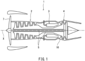
- FIG. 1 is a schematic sectional view of the gas turbine 1 of Embodiment 1.
- the gas turbine 1 includes a compressor 2, the combustor 3, a turbine 4, a rotating shaft 5, a casing 10, and a fan 7.
- air introduced into the casing 10 from an outside is compressed by the compressor 2, and the compressed air compressed by the compressor 2 is guided to the combustor 3.
- energy of a high-temperature high-pressure combustion gas obtained by combusting fuel together with the compressed air in the combustor 3 is taken out as rotational power in the turbine 4.
- the turbine 4 is coupled to the compressor 2 through the rotating shaft 5.
- the axis X of the rotating shaft 5 is the axis of the gas turbine 1.
- the fan 7 is connected to a front end portion of the rotating shaft 5.
- the rotational power generated by the turbine 4 drives the compressor 2 and the fan 7.
- a turbo fan engine drives a fan by rotational power mainly generated by a turbine and is used as an aircraft engine.
- FIG. 1 shows the turbo fan engine that is a form of the gas turbine. However, the form of the gas turbine is not limited to this.
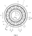
- FIG. 2 is a schematic diagram when viewed from the downstream side in the flow direction of the compressed air in the combustor 3 of the gas turbine 1 of FIG. 1 .
- the combustor 3 has a tubular shape.
- the combustor 3 is an annular combustor having an annular shape surrounding the axis X of the gas turbine 1.
- the combustor 3 may be of a type other than the annular type.
- the casing 10 includes: a tubular outer casing 11; and a tubular inner casing 12 concentrically located inside the outer casing 11.
- the outer casing 11 and the inner casing 12 define an annular internal space.
- An inside of the combustor 3 denotes an inside of the outer casing 11 in the radial direction R and an outside of the inner casing 12 in the radial direction R.
- the fuel injectors 17 that inject the fuel to the combustion chamber 16 are annularly lined up along the combustion chamber 16 at the upstream side of the combustion chamber 16.
- the fuel injectors 17 are lined up in the circumferential direction C on a virtual circle that is concentric with the shell 13.
- An ignition plug 18 is located at the shell 13.
- the ignition plug 18 generates a spark for igniting a fuel-air mixture in the combustion chamber 16 at the start of the gas turbine 1.
- a liner 20 is located in the annular internal space of the shell 13 so as to be concentric with the casing 10 and the shell 13.
- the liner 20 is made of, for example, a ceramic matrix composite (CMC).
- the liner 20 includes: a tubular outer liner 21; and a tubular inner liner 22 concentrically located inside the outer liner 21.
- the outer liner 21 covers an inner peripheral surface of the outer shell 14.
- the inner liner 22 covers an outer peripheral surface of the inner shell 15.
- the outer liner 21 may be an assembly of liner panels 31 which are adjacently lined up in the circumferential direction so as to form a tubular shape.
- the inner liner 22 may be an assembly of liner panels 32 which are adjacently lined up in the circumferential direction so as to form a tubular shape.
- One or each of the outer liner 21 and the inner liner 22 may be a tubular body integrally molded in a tubular shape without being divided into the liner panels lined up in the circumferential direction.
- each liner panel is not limited to a circular-arc plate and may be a flat plate.
- the liner including the liner panels does not have to have a cylindrical shape and may have a polygonal tubular shape.
- FIG. 3 is a sectional view taken along line III-III of the combustor 3 of FIG. 2 .
- a diffuser 8 is located at an upstream portion of the casing 10.
- the diffuser 8 takes the compressed air, generated by the compressor 2, into the casing 10.
- the fuel injectors 17 are supported by a stem 9 fixed to the casing 10.
- Part of the compressed air taken into a space S1 in the casing 10 is supplied to the fuel injectors 17 for combustion.
- the rest of the compressed air taken into the space S1 in the casing 10 cools an outer surface of the shell 13, and part of the rest of the compressed air is supplied as cooling air into the shell 13 through openings 14b (see FIG. 4 ) of the outer shell 14.
- the outer liner 21 is located so as to be spaced apart from the outer shell 14 toward the inside in the radial direction R.
- the inner liner 22 is located so as to be spaced apart from the inner shell 15 toward the outside in the radial direction R.
- the outer liner 21 and the inner liner 22 are attached to the shell 13 by fixtures 40 (see FIG. 4 ) so as to be spaced apart from the shell 13.
- the outer liner 21 and the inner liner 22 define the combustion chamber 16.
- a combustion gas in the combustion chamber 16 is discharged toward the turbine 4 (see FIG. 1 ) through the discharge port 16a defined by an end of the outer liner 21 and an end of the inner liner 22 which are located at the downstream side in the flow direction F of the compressed air in the combustion chamber 16.
- An attaching structure in which the outer liner 21 is attached to the outer shell 14 and an attaching structure in which the inner liner 22 is attached to the inner shell 15 are the same as each other. Therefore, the following will mainly describe the attaching structure in which the outer liner 21 is attached to the outer shell 14.
- FIG. 4 is a partial sectional view of the combustor 3 of FIG. 3 .
- the outer shell 14 includes through holes 14a for attachment and the openings 14b for cooling.
- Each liner panel 31 includes support holes 31a for attachment.
- the support holes 31a of the liner panel 31 are located so as to coincide with the through holes 14a of the outer shell 14 in the radial direction R.
- An inner peripheral surface of each support hole 31a has a shape corresponding to the fixture 40.
- the inner peripheral surface of the support hole 31a includes a tapered surface that increases in diameter toward the inside in the radial direction R.
- the fixtures 40 attach the liner panel 31 to the outer shell 14.
- the fixtures 40 are made of, for example, metal, but may be made of a material other than the metal.
- the fixture 40 is an assembly including a support 41, a fixing structure 42, a spacer 43, and a biasing structure 44.
- the support 41 is inserted into the support hole 31a of the liner panel 31 and the through hole 14a of the outer shell 14 from the inside in the radial direction R.
- the support 41 includes a shaft portion 41a, a head portion 41b, and an air passage 41c connected to the combustion chamber 16.
- the shaft portion 41a extends in the radial direction R and is inserted into the through hole 14a of the outer shell 14.
- a central axis Y of the shaft portion 41a extends in the radial direction R.
- a portion of an outer peripheral surface of the shaft portion 41a which is located outside the outer shell 14 in the radial direction R includes a screw or an engagement groove.
- the outer peripheral surface of the head portion 41b and the inner peripheral surface of the support hole 31a may not include the tapered surfaces, and the head portion 41b of the support 41 may be brought into contact with a surface of the liner panel 31 which is located at the inside in the radial direction R.
- the air passage 41c extends inside the support 41 along the central axis Y of the support 41 from the shaft portion 41a to the head portion 41b.
- the air passage 41c is open to the combustion chamber 16 and the space S1 which is located outside the outer shell 14 in the radial direction R.
- a portion of the air passage 41c which is located at the inside in the radial direction R has a truncated cone shape that expands toward the combustion chamber 16.
- the air passage 41c may include a swirl generator that makes the air flowing through the air passage 41c swirl.
- the swirl generator is, for example, an air inlet which is inclined relative to the central axis Y of the support 41 and through which the air is supplied to the air passage 41c.
- the support 41 may not include the air passage 41c.
- a seal structure (not shown) is located between the outer shell 14 and the liner panel 31. The seal structure prevents the cooling air from leaking from the cooling space S2.
- the support 41 includes the air passage 41c
- the compressed air in the space S1 flows through the air passage 41c and is discharged as the cooling air to the combustion chamber 16 along an inside surface of the liner panel 31.
- the fixing structure 42 is attached to the shaft portion 41a of the support 41 at the outside of the outer shell 14 in the radial direction R.
- an outer shape of the fixing structure 42 is larger than the through hole 14a of the outer shell 14.
- the fixing structure 42 is attached to the shaft portion 41a of the support 41 so as to prevent the support 41 from coming out from the outer shell 14 to the inside in the radial direction R.
- the fixing structure 42 is attached so as not to be displaceable relative to the support 41 in the direction in which the central axis Y extends.
- the fixing structure 42 is a C-shaped clip that is engaged with the engagement groove of the outer peripheral surface of the shaft portion 41a.
- the fixing structure 42 may be a nut that is threadedly engaged with the screw of the outer peripheral surface of the shaft portion 41a.
- the fixing structure 42 and the shaft portion 41a may be attached to each other by any method.
- the fixing structure 42 is directly opposed to an outer surface of the outer shell 14, another structure may be interposed between the fixing structure 42 and the outer shell 14.
- the spacer 43 is interposed between the outer shell 14 and the liner panel 31.
- the spacer 43 has a ring shape around the central axis Y.
- the spacer 43 is externally fitted to the shaft portion 41a of the support 41 with a play.
- the spacer 43 includes a main body portion 43a and a projecting portion 43b.
- the main body portion 43a is located between the outer shell 14 and the liner panel 31.
- the main body portion 43a has, for example, a ring plate shape. When viewed in the direction in which the central axis Y extends, an outer shape of the main body portion 43a is larger than the through hole 14a of the outer shell 14.
- the projecting portion 43b projects from the main body portion 43a to the outside in the radial direction R and is inserted into the through hole 14a of the outer shell 14.
- the projecting portion 43b has a tubular shape.
- the spacer 43 is displaceable relative to the outer shell 14 in a direction orthogonal to the central axis Y.
- the biasing structure 44 biases the liner panel 31 toward the inside in the radial direction R such that the liner panel 31 separates from the outer shell 14 in the radial direction R.
- the biasing structure 44 is, for example, an annular disc spring.
- the biasing structure 44 has a ring shape around the central axis Y.
- the biasing structure 44 is not limited to this, and may be, for example, a coil spring wound around the central axis Y.
- the biasing structure 44 is externally fitted to the shaft portion 41a of the support 41 with a play.
- the biasing structure 44 includes a base portion 44a and an elastic portion 44b.
- the base portion 44a is sandwiched between the spacer 43 and the liner panel 31 in the radial direction R.
- the elastic portion 44b is located outside the spacer 43 in the direction orthogonal to the central axis Y of the support 41.
- the elastic portion 44b projects from the base portion 44a toward the outer shell 14.
- the elastic portion 44b biases the outer shell 14 toward the outside in the radial direction R.
- the base portion 44a biases the liner panel 31 toward the inside in the radial direction R by reaction force applied to the elastic portion 44b from the outer shell 14.
- the liner panel 31 is displaced by the biasing structure 44 toward the inside in the radial direction R.
- the support 41, the fixing structure 42, and the spacer 43 are displaced toward the inside in the radial direction R, and this forms a gap G2 between the main body portion 43a of the spacer 43 and the outer shell 14 in the radial direction R.
- the fixing structure 42 directly presses the projecting portion 43b of the spacer 43 toward the inside in the radial direction R but may indirectly press the projecting portion 43b.
- the liner panel 31 can be displaced against the biasing force of the biasing structure 44 so as to reduce the the gap G2 between the spacer 43 and the outer shell 14, and this can reduce the stress of the liner panel 31.
- the liner panel 31 can be displaced in the gap G1 between the outer shell 14 and the spacer 43, and this can reduce the stress of the liner panel 31. Therefore, the durability of the liner panel 31 in the combustor 3 of the gas turbine 1 can be improved.
- the biasing structure 44 includes the base portion 44a and the elastic portion 44b, the biasing structure 44 that forms the gap G2 between the spacer 43 and the outer shell 14 can be easily attached by a small number of parts.
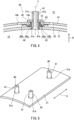
- FIG. 5 is a perspective view showing the liner panel 31 and the supports 41 in the combustor 3 of FIG. 2 .
- FIG. 5 shows the supports 41 of the fixtures 40, but the fixing structures 42, the spacers 43, and the biasing structures 44 of the fixtures 40 and the outer shell 14 are not shown.
- the liner panel 31 is supported by three fixtures 40 as three-point support.
- the liner panel 31 extends in the axial direction X of the combustor 3.
- Two fixtures 40 are located at one of longitudinal-direction portions of the liner panel 31, and one fixture 40 is located at the other longitudinal-direction portion of the liner panel 31.
- the three fixtures 40 are located at respective positions that are vertices of an isosceles triangle. The positions of the three fixtures 40 are not limited to these, and may be any positions.
- An in-plane direction of the liner panel 31 is determined by the three-point support using the three fixtures 40. Therefore, even when the thermal expansion difference is generated between the outer shell 14 and the liner panel 31, the change in the posture of the liner panel 31 can be suppressed. Moreover, since support points of the liner panel 31 are three points, binding power can be prevented from acting in an out-of-plane direction of the liner panel 31. Therefore, the durability of the liner panel 31 in the combustor 3 of the gas turbine 1 can be improved. Moreover, since the change in the posture of the liner panel 31 is suppressed, seal performance of the seal structure located between the liner panel 31 and the outer shell 14 can be easily maintained as designed.
- FIG. 6 is a partial sectional view of a combustor 103 of Embodiment 2.
- the same reference signs are used for the same components as Embodiment 1, and explanations thereof are omitted.
- the liner panel 31 is attached to the outer shell 14 by fixtures 140.
- one liner panel 31 can be attached to the outer shell 14 by three fixtures 140 as the three-point support.
- Each fixture 140 includes the support 41, a fixing structure 142, the spacer 43, a biasing structure 144, a pressing structure 145, and fasteners 146.
- the pressing structure 145 covers the fixing structure 142 from the outside in the radial direction R and is fixed to the outer shell 14 by the fasteners 146.
- the pressing structure 145 includes a recess portion 145a and a flange portion 145b.
- the recess portion 145a is recessed toward the outside in the radial direction R and is open toward the inside in the radial direction R.
- the flange portion 145b projects in the direction orthogonal to the central axis Y of the support 41 from an end portion of the recess portion 145a which is located at the inside in the radial direction R.
- the flange portion 145b of the pressing structure 145 is fixed to the outer shell 14 by the fasteners 146.
- Each fastener 146 includes, for example, a bolt 147 and a nut 148.
- the fastener 146 may be something else (rivet, for example) as long as it can fix the pressing structure 145 to the outer shell 14.
- the fixing structure 142 and the biasing structure 144 are accommodated in a space between the recess portion 145a of the pressing structure 145 and the outer shell 14.
- the fixing structure 142 is attached to the shaft portion 41a of the support 41 at the outside of the outer shell 14 in the radial direction R.
- an outer shape of the fixing structure 142 is larger than the through hole 14a of the outer shell 14.
- the fixing structure 142 is a nut that is threadedly engaged with the screw of the outer peripheral surface of the shaft portion 41a of the support 41.
- the biasing structure 144 is sandwiched between a bottom portion of the recess portion 145a of the pressing structure 145 and the fixing structure 142.
- the fixing structure 142 is a lower seat that supports the biasing structure 144 from the inside in the radial direction R
- the pressing structure 145 is an upper seat that supports the biasing structure 144 from the outside in the radial direction R.
- the biasing structure 144 presses the fixing structure 142 toward the inside in the radial direction R to bias the support 41 and the fixing structure 142 toward the inside in the radial direction R.
- the biasing structure 144 includes a coil spring wound around the central axis Y.
- the biasing structure 144 may be an elastic body (disc spring, for example) other than the coil spring.
- the recess portion 145a of the pressing structure 145 includes an insertion hole 145c.
- the shaft portion 41a of the support 41 is inserted into the insertion hole 145c of the recess portion 145a in the radial direction R.
- the shaft portion 41a does not have to be inserted into the insertion hole 145c.
- the support 41, the fixing structure 142, and the spacer 43 are displaced toward the inside in the radial direction R by the biasing structure 144.
- the liner panel 31 is pressed toward the inside in the radial direction R, and this forms the gap G2 between the main body portion 43a of the spacer 43 and the outer shell 14 in the radial direction R.
- the liner panel 31 can be displaced against the biasing force of the biasing structure 144 so as to reduce the the gap G2 between the spacer 43 and the outer shell 14, and this can reduce the stress of the liner panel 31.
- the liner panel 31 can be displaced in the gap G1 between the outer shell 14 and the spacer 43, and this can reduce the stress of the liner panel 31. Therefore, the durability of the liner panel 31 in the combustor 103 can be improved.
- the biasing structure 144 since the biasing structure 144 is located at the outside of the outer shell 14 in the radial direction R, the biasing structure 144 can be located away from the heat of the combustion chamber 16, and this can reduce a heat load of the biasing structure 144. Moreover, since the fixing structure 142 presses the projecting portion 43b of the spacer 43 toward the inside in the radial direction R, the gap G2 between the spacer 43 and the outer shell 14 can be maintained while preventing vibrations of the spacer 43. Since the other components are the same as those in Embodiment 1, explanations thereof are omitted.
- FIG. 7 is a partial sectional view of a combustor 203 of Embodiment 3.
- the same reference signs are used for the same components as Embodiment 1, and explanations thereof are omitted.
- the liner panel 31 is attached to the outer shell 14 by fixtures 240.
- one liner panel 31 can be attached to the outer shell 14 by three fixtures 240 as the three-point support.
- Each fixture 240 includes the support 41, a fixing structure 242, a spacer 243, and a biasing structure 244.
- the fixing structure 242 is attached to the shaft portion 41a of the support 41 at the outside of the outer shell 14 in the radial direction R.
- the fixing structure 242 is a nut that is threadedly engaged with the screw of the outer peripheral surface of the shaft portion 41a, but may be another structure, such as a clip.
- the biasing structure 244 is located between the fixing structure 242 and the outer shell 14 in the radial direction R.
- the biasing structure 244 is an assembly including an elastic body 250, a lower seat 251, and an upper seat 252.
- the elastic body 250 is, for example, a spring.
- the elastic body 250 is a coil spring wound around the central axis Y, but may be something else (disc spring, for example).
- the lower seat 251 is located at the inside of the elastic body 250 in the radial direction R.
- the upper seat 252 is located at the outside of the elastic body 250 in the radial direction R.
- the lower seat 251 and the upper seat 252 include respective opposing surfaces 251a and 252a which bypass the elastic body 250 and are opposed to each other in the radial direction R. Since the upper seat 252 is pressed by the biasing structure 244 toward the outside in the radial direction R, a gap G3 is formed between the opposing surface 251a of the lower seat 251 and the opposing surface 252a of the upper seat 252 in the radial direction R.
- the spacer 243 has a ring shape around the central axis Y.
- the spacer 243 includes a main body portion 243a and a projecting portion 243b.
- the main body portion 243a is sandwiched between the outer shell 14 and the liner panel 31.
- an outer shape of the main body portion 243a is larger than the through hole 14a of the outer shell 14.
- the main body portion 243a has, for example, a ring plate shape.
- the projecting portion 243b projects from the main body portion 243a toward the outside in the radial direction R, passes through the through hole 14a of the outer shell 14, and contacts the upper seat 252 from the inside in the radial direction R.
- the projecting portion 243b has, for example, a tubular shape.
- FIG. 7 shows that the operation of the gas turbine 1 is in a stop state.
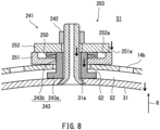
- FIG. 8 is a partial sectional view of the combustor 203 of FIG. 7 while the gas turbine is operating.
- the compressed air flowing into the space S1 from the compressor 2 flows into the cooling space S2 through the openings 14b of the outer shell 14.
- the compressed air in the cooling space S2 displaces the liner panel 31 toward the inside in the radial direction R against the biasing force of the elastic body 250.
- the support 41, the fixing structure 242, and the spacer 243 are displaced toward the inside in the radial direction R.
- the opposing surface 252a of the upper seat 252 is brought into contact with the opposing surface 251a of the lower seat 251
- the displacement of the liner panel 31 toward the inside in the radial direction R stops. This forms the gap G2 between the spacer 243 and the outer shell 14 in the radial direction R.
- the gas turbine starts, and the compressed air flowing into the cooling space S2 from the compressor 2 displaces the liner panel 31 toward the inside in the radial direction R against the biasing structure 244.
- This forms the gap G2 between the spacer 243 and the outer shell 14 in the radial direction R.
- the liner panel 31 can be displaced so as to reduce the distance between the spacer 243 and the outer shell 14, and this can reduce the stress of the liner panel 31.
- the liner panel 31 can be displaced in the gap G1 between the outer shell 14 and the spacer 243, and this can reduce the stress of the liner panel 31. Therefore, the durability of the liner panel 31 in the combustor 203 can be improved.
- the biasing structure 244 since the biasing structure 244 is located at the outside of the outer shell 14 in the radial direction R, the biasing structure 244 can be located away from the heat of the combustion chamber 16, and this can reduce the heat load of the biasing structure 244. Furthermore, since the biasing structure 244 is the above-described assembly, the fixing structure 242 can be biased toward the outside in the radial direction R by a simple configuration. Moreover, when the compressed air flowing into the cooling space S2 from the compressor 2 displaces the liner panel 31 toward the inside in the radial direction R so as to reduce the distance between the upper seat 252 and the lower seat 251, the upper seat 252 and the lower seat 251 are brought into contact with each other, and this stops the displacement. Therefore, the elastic body 250 can be protected.
- the liner panel can be displaced against the biasing force of the biasing structure so as to reduce the gap between the spacer and the shell, and this can reduce the stress of the liner panel.
- the liner panel can be displaced by the gap between the shell and the spacer, and this can reduce the stress of the liner panel. Therefore, the durability of the liner panel in the combustor of the gas turbine can be improved.
- the combustor according to the first aspect wherein the biasing structure biases the support, the fixing structure, and the spacer toward the inside in the radial direction to form the gap between the spacer and the shell in the radial direction.
- the liner panel can contract in the radial direction. Therefore, the stress of the liner panel can be reduced. Moreover, the liner panel can be displaced in the gap between the shell and the spacer, and this can reduce the stress of the liner panel. Therefore, the durability of the liner panel in the combustor of the gas turbine can be improved.
- the vibrations of the spacer can be suppressed.
- the biasing structure since the biasing structure is located outside the shell in the radial direction, the heat load applied from the combustion chamber to the biasing structure can be suppressed.
- biasing structure includes:
- the biasing structure that forms the gap between the spacer and the shell can be easily attached by a small number of parts.
- a combustor of a gas turbine including:
- the fixing structure can be biased toward the outside in the radial direction by a simple configuration.
- a combustor of a gas turbine including:
- the in-plane direction of the liner is determined by the three-point support. Therefore, even when the thermal expansion difference is generated between the shell and the liner, the change in the posture of the liner can be suppressed. Moreover, since the support points of the liner are three points, the binding power can be prevented from acting in the out-of-plane direction of the liner. Therefore, the durability of the liner in the combustor of the gas turbine can be improved.
Landscapes
- Engineering & Computer Science (AREA)
- Chemical & Material Sciences (AREA)
- Combustion & Propulsion (AREA)
- Mechanical Engineering (AREA)
- General Engineering & Computer Science (AREA)
- Ceramic Engineering (AREA)
- Turbine Rotor Nozzle Sealing (AREA)
Abstract
Description
- The present disclosure relates to a combustor of a gas turbine.
- In recent years, a combustion temperature in a gas turbine is increasing for the purpose of improving fuel efficiency. Proposed as a combustor of the gas turbine is a combustor in which a liner is located inside a shell surrounding a combustion chamber and is fastened to the shell with a bolt (see
PTL 1, for example). - PTL 1:
US 2020/0003417 A1 - While the gas turbine is operating, a thermal expansion difference is generated between the shell and the liner by a temperature difference between the shell and the liner, a difference between thermal expansion coefficients of materials, a temperature difference between front and rear surfaces of the liner, and the like. Therefore, binding power is generated at the liner through the bolt, and this may reduce the life of the liner.
- An object of one aspect of the present disclosure is to improve durability of a liner in a combustor of a gas turbine.
- A combustor of a gas turbine according to one aspect of the present disclosure includes: a shell surrounding a combustion chamber; a liner located inside the shell and facing the combustion chamber; and a fixture by which the liner is attached to the shell. The fixture includes: a support including a shaft portion and a head portion, the shaft portion penetrating the shell, the head portion being connected to the shaft portion and supporting the liner from an inside of the shell in a radial direction; a fixing structure attached to the shaft portion of the support at an outside of the shell in the radial direction; a spacer interposed between the shell and the liner; and a biasing structure that biases the liner toward the inside in the radial direction to separate the liner from the shell in the radial direction and form a gap between the spacer and the shell in the radial direction.
- A combustor of a gas turbine according to another aspect of the present disclosure includes: a shell surrounding a combustion chamber; a liner located inside the shell and facing the combustion chamber; a cooling space into which compressed air flows and which is located between the shell and the liner; and a fixture by which the liner is attached to the shell. The fixture includes: a support including a shaft portion and a head portion, the shaft portion penetrating the shell, the head portion being connected to the shaft portion and supporting the liner from an inside of the shell in a radial direction; a spacer interposed between the shell and the liner; a fixing structure attached to the shaft portion of the support at an outside of the shell in the radial direction; and a biasing structure that is located outside the shell in the radial direction and located inside the fixing structure in the radial direction and biases the fixing structure toward the outside in the radial direction such that the liner approaches the shell in the radial direction against the compressed air flowing into the cooling space.
- A combustor of a gas turbine according to yet another aspect of the present disclosure includes: a shell surrounding a combustion chamber; liner panels located inside the shell and facing the combustion chamber; and fixtures which attach the liner panels to the shell. The liner panels are located in a circumferential direction of the shell, and three of the fixtures support one of the liner panels by three-point support.
- According to one aspect of the present disclosure, the durability of the liner in the combustor of the gas turbine can be improved.
-
-
FIG. 1 is a schematic sectional view of a gas turbine according toEmbodiment 1. -
FIG. 2 is a sectional view when viewed from a downstream side in a flow direction of compressed air of a combustor of the gas turbine ofFIG. 1 . -
FIG. 3 is a sectional view taken along line III-III of the combustor ofFIG. 2 . -
FIG. 4 is a partial sectional view of the combustor ofFIG. 3 . -
FIG. 5 is a perspective view showing a liner panel and supports in the combustor ofFIG. 2 . -
FIG. 6 is a partial sectional view of the combustor ofEmbodiment 2. -
FIG. 7 is a partial sectional view of the combustor ofEmbodiment 3. -
FIG. 8 is an enlarged partial sectional view of the combustor ofFIG. 7 while the gas turbine is operating. - Hereinafter, embodiments will be described with reference to the drawings. An axis X of a
gas turbine 1 is the same as an axis of acombustor 3. A direction orthogonal to the axis X of thecombustor 3 is referred to as a radial direction R of thecombustor 3. A direction extending around the axis X is referred to as a circumferential direction C of thecombustor 3. Regarding a flow direction F of compressed air in acombustion chamber 16, a side towardfuel injectors 17 is referred to as an upstream side, and a side toward adischarge port 16a is referred to as a downstream side. -
FIG. 1 is a schematic sectional view of thegas turbine 1 ofEmbodiment 1. As shown inFIG. 1 , thegas turbine 1 includes acompressor 2, thecombustor 3, aturbine 4, arotating shaft 5, acasing 10, and a fan 7. In thegas turbine 1, air introduced into thecasing 10 from an outside is compressed by thecompressor 2, and the compressed air compressed by thecompressor 2 is guided to thecombustor 3. Then, energy of a high-temperature high-pressure combustion gas obtained by combusting fuel together with the compressed air in thecombustor 3 is taken out as rotational power in theturbine 4. - The
turbine 4 is coupled to thecompressor 2 through the rotatingshaft 5. The axis X of therotating shaft 5 is the axis of thegas turbine 1. The fan 7 is connected to a front end portion of the rotatingshaft 5. The rotational power generated by theturbine 4 drives thecompressor 2 and the fan 7. There are various types of gas turbines. A turbo fan engine drives a fan by rotational power mainly generated by a turbine and is used as an aircraft engine.FIG. 1 shows the turbo fan engine that is a form of the gas turbine. However, the form of the gas turbine is not limited to this. -
FIG. 2 is a schematic diagram when viewed from the downstream side in the flow direction of the compressed air in thecombustor 3 of thegas turbine 1 ofFIG. 1 . As shown inFIG. 2 , thecombustor 3 has a tubular shape. For example, thecombustor 3 is an annular combustor having an annular shape surrounding the axis X of thegas turbine 1. Thecombustor 3 may be of a type other than the annular type. In thecombustor 3, thecasing 10 includes: a tubularouter casing 11; and a tubularinner casing 12 concentrically located inside theouter casing 11. Theouter casing 11 and theinner casing 12 define an annular internal space. An inside of thecombustor 3 denotes an inside of theouter casing 11 in the radial direction R and an outside of theinner casing 12 in the radial direction R. - A
shell 13 as a combustion liner is located in the annular internal space of thecasing 10 so as to be concentric with thecasing 10. Theshell 13 surrounds thecombustion chamber 16. Theshell 13 is made of, for example, metal. Theshell 13 includes: a tubularouter shell 14; and a tubularinner shell 15 concentrically located inside theouter shell 14. An inside of theshell 13 denotes an inside of theouter shell 14 in the radial direction R and an outside of theinner shell 15 in the radial direction R. - The
fuel injectors 17 that inject the fuel to thecombustion chamber 16 are annularly lined up along thecombustion chamber 16 at the upstream side of thecombustion chamber 16. Thefuel injectors 17 are lined up in the circumferential direction C on a virtual circle that is concentric with theshell 13. Anignition plug 18 is located at theshell 13. Theignition plug 18 generates a spark for igniting a fuel-air mixture in thecombustion chamber 16 at the start of thegas turbine 1. Aliner 20 is located in the annular internal space of theshell 13 so as to be concentric with thecasing 10 and theshell 13. - The
liner 20 is made of, for example, a ceramic matrix composite (CMC). Theliner 20 includes: a tubularouter liner 21; and a tubularinner liner 22 concentrically located inside theouter liner 21. Theouter liner 21 covers an inner peripheral surface of theouter shell 14. Theinner liner 22 covers an outer peripheral surface of theinner shell 15. - The
outer liner 21 may be an assembly ofliner panels 31 which are adjacently lined up in the circumferential direction so as to form a tubular shape. Similarly, theinner liner 22 may be an assembly ofliner panels 32 which are adjacently lined up in the circumferential direction so as to form a tubular shape. One or each of theouter liner 21 and theinner liner 22 may be a tubular body integrally molded in a tubular shape without being divided into the liner panels lined up in the circumferential direction. Moreover, each liner panel is not limited to a circular-arc plate and may be a flat plate. The liner including the liner panels does not have to have a cylindrical shape and may have a polygonal tubular shape. -
FIG. 3 is a sectional view taken along line III-III of thecombustor 3 ofFIG. 2 . As shown inFIG. 3 , adiffuser 8 is located at an upstream portion of thecasing 10. Thediffuser 8 takes the compressed air, generated by thecompressor 2, into thecasing 10. Thefuel injectors 17 are supported by a stem 9 fixed to thecasing 10. Part of the compressed air taken into a space S1 in thecasing 10 is supplied to thefuel injectors 17 for combustion. The rest of the compressed air taken into the space S1 in thecasing 10 cools an outer surface of theshell 13, and part of the rest of the compressed air is supplied as cooling air into theshell 13 throughopenings 14b (seeFIG. 4 ) of theouter shell 14. - The
outer liner 21 is located so as to be spaced apart from theouter shell 14 toward the inside in the radial direction R. Theinner liner 22 is located so as to be spaced apart from theinner shell 15 toward the outside in the radial direction R. Theouter liner 21 and theinner liner 22 are attached to theshell 13 by fixtures 40 (seeFIG. 4 ) so as to be spaced apart from theshell 13. Theouter liner 21 and theinner liner 22 define thecombustion chamber 16. A combustion gas in thecombustion chamber 16 is discharged toward the turbine 4 (seeFIG. 1 ) through thedischarge port 16a defined by an end of theouter liner 21 and an end of theinner liner 22 which are located at the downstream side in the flow direction F of the compressed air in thecombustion chamber 16. - An attaching structure in which the
outer liner 21 is attached to theouter shell 14 and an attaching structure in which theinner liner 22 is attached to theinner shell 15 are the same as each other. Therefore, the following will mainly describe the attaching structure in which theouter liner 21 is attached to theouter shell 14. -
FIG. 4 is a partial sectional view of thecombustor 3 ofFIG. 3 . As shown inFIG. 4 , theouter shell 14 includes throughholes 14a for attachment and theopenings 14b for cooling. Eachliner panel 31 includessupport holes 31a for attachment. The support holes 31a of theliner panel 31 are located so as to coincide with the throughholes 14a of theouter shell 14 in the radial direction R. An inner peripheral surface of eachsupport hole 31a has a shape corresponding to thefixture 40. For example, the inner peripheral surface of thesupport hole 31a includes a tapered surface that increases in diameter toward the inside in the radial direction R. - The
fixtures 40 attach theliner panel 31 to theouter shell 14. Thefixtures 40 are made of, for example, metal, but may be made of a material other than the metal. Thefixture 40 is an assembly including asupport 41, a fixingstructure 42, aspacer 43, and a biasingstructure 44. - The
support 41 is inserted into thesupport hole 31a of theliner panel 31 and the throughhole 14a of theouter shell 14 from the inside in the radial direction R. Thesupport 41 includes ashaft portion 41a, ahead portion 41b, and anair passage 41c connected to thecombustion chamber 16. Theshaft portion 41a extends in the radial direction R and is inserted into the throughhole 14a of theouter shell 14. A central axis Y of theshaft portion 41a extends in the radial direction R. A portion of an outer peripheral surface of theshaft portion 41a which is located outside theouter shell 14 in the radial direction R includes a screw or an engagement groove. - The
head portion 41b is connected to an end portion of theshaft portion 41a which is located at the inside in the radial direction R. An outer diameter of thehead portion 41b is larger than an outer diameter of theshaft portion 41a. An outer peripheral surface of thehead portion 41b includes a tapered surface that increases in diameter from the outside to the inside in the radial direction R. Thehead portion 41b is located at thesupport hole 31a of theliner panel 31. The tapered surface of the outer peripheral surface of thehead portion 41b is brought into contact with the tapered surface of the inner peripheral surface of thesupport hole 31a from the inside in the radial direction R. To be specific, thehead portion 41b supports theliner panel 31 from the inside in the radial direction R. The outer peripheral surface of thehead portion 41b and the inner peripheral surface of thesupport hole 31a may not include the tapered surfaces, and thehead portion 41b of thesupport 41 may be brought into contact with a surface of theliner panel 31 which is located at the inside in the radial direction R. - The
air passage 41c extends inside thesupport 41 along the central axis Y of thesupport 41 from theshaft portion 41a to thehead portion 41b. Theair passage 41c is open to thecombustion chamber 16 and the space S1 which is located outside theouter shell 14 in the radial direction R. A portion of theair passage 41c which is located at the inside in the radial direction R has a truncated cone shape that expands toward thecombustion chamber 16. Theair passage 41c may include a swirl generator that makes the air flowing through theair passage 41c swirl. The swirl generator is, for example, an air inlet which is inclined relative to the central axis Y of thesupport 41 and through which the air is supplied to theair passage 41c. Thesupport 41 may not include theair passage 41c. - The compressed air flowing into the space S1 from the compressor 2 (see
FIG. 1 ) through the diffuser 8 (seeFIG. 3 ) flows through theopenings 14b of theouter shell 14 into a cooling space S2 between theouter shell 14 and theliner panel 31 as cooling air. A seal structure (not shown) is located between theouter shell 14 and theliner panel 31. The seal structure prevents the cooling air from leaking from the cooling space S2. Moreover, when thesupport 41 includes theair passage 41c, the compressed air in the space S1 flows through theair passage 41c and is discharged as the cooling air to thecombustion chamber 16 along an inside surface of theliner panel 31. - The fixing
structure 42 is attached to theshaft portion 41a of thesupport 41 at the outside of theouter shell 14 in the radial direction R. When viewed in a direction in which the central axis Y extends, an outer shape of the fixingstructure 42 is larger than the throughhole 14a of theouter shell 14. The fixingstructure 42 is attached to theshaft portion 41a of thesupport 41 so as to prevent thesupport 41 from coming out from theouter shell 14 to the inside in the radial direction R. The fixingstructure 42 is attached so as not to be displaceable relative to thesupport 41 in the direction in which the central axis Y extends. For example, the fixingstructure 42 is a C-shaped clip that is engaged with the engagement groove of the outer peripheral surface of theshaft portion 41a. The fixingstructure 42 may be a nut that is threadedly engaged with the screw of the outer peripheral surface of theshaft portion 41a. The fixingstructure 42 and theshaft portion 41a may be attached to each other by any method. Moreover, although the fixingstructure 42 is directly opposed to an outer surface of theouter shell 14, another structure may be interposed between the fixingstructure 42 and theouter shell 14. - The
spacer 43 is interposed between theouter shell 14 and theliner panel 31. Thespacer 43 has a ring shape around the central axis Y. However, the shape of thespacer 43 is not limited to this. Thespacer 43 is externally fitted to theshaft portion 41a of thesupport 41 with a play. Thespacer 43 includes amain body portion 43a and a projectingportion 43b. Themain body portion 43a is located between theouter shell 14 and theliner panel 31. Themain body portion 43a has, for example, a ring plate shape. When viewed in the direction in which the central axis Y extends, an outer shape of themain body portion 43a is larger than the throughhole 14a of theouter shell 14. - The projecting
portion 43b projects from themain body portion 43a to the outside in the radial direction R and is inserted into the throughhole 14a of theouter shell 14. The projectingportion 43b has a tubular shape. There is a gap G1 between the inner peripheral surface of the throughhole 14a of theouter shell 14 and the projectingportion 43b. To be specific, thespacer 43 is displaceable relative to theouter shell 14 in a direction orthogonal to the central axis Y. - The biasing
structure 44 biases theliner panel 31 toward the inside in the radial direction R such that theliner panel 31 separates from theouter shell 14 in the radial direction R. The biasingstructure 44 is, for example, an annular disc spring. The biasingstructure 44 has a ring shape around the central axis Y. The biasingstructure 44 is not limited to this, and may be, for example, a coil spring wound around the central axis Y. The biasingstructure 44 is externally fitted to theshaft portion 41a of thesupport 41 with a play. - The biasing
structure 44 includes abase portion 44a and anelastic portion 44b. Thebase portion 44a is sandwiched between thespacer 43 and theliner panel 31 in the radial direction R. Theelastic portion 44b is located outside thespacer 43 in the direction orthogonal to the central axis Y of thesupport 41. Theelastic portion 44b projects from thebase portion 44a toward theouter shell 14. Theelastic portion 44b biases theouter shell 14 toward the outside in the radial direction R. Thebase portion 44a biases theliner panel 31 toward the inside in the radial direction R by reaction force applied to theelastic portion 44b from theouter shell 14. - The
liner panel 31 is displaced by the biasingstructure 44 toward the inside in the radial direction R. Thesupport 41, the fixingstructure 42, and thespacer 43 are displaced toward the inside in the radial direction R, and this forms a gap G2 between themain body portion 43a of thespacer 43 and theouter shell 14 in the radial direction R. The fixingstructure 42 directly presses the projectingportion 43b of thespacer 43 toward the inside in the radial direction R but may indirectly press the projectingportion 43b. - According to the above-described configuration, even when a thermal expansion difference is generated between the
outer shell 14 and theliner panel 31 by a temperature difference between the shell and the liner, a difference between thermal expansion coefficients of materials, a temperature difference between front and rear surfaces of the liner, and the like, theliner panel 31 can be displaced against the biasing force of the biasingstructure 44 so as to reduce the the gap G2 between thespacer 43 and theouter shell 14, and this can reduce the stress of theliner panel 31. Moreover, theliner panel 31 can be displaced in the gap G1 between theouter shell 14 and thespacer 43, and this can reduce the stress of theliner panel 31. Therefore, the durability of theliner panel 31 in thecombustor 3 of thegas turbine 1 can be improved. - Since the biasing
structure 44 includes thebase portion 44a and theelastic portion 44b, the biasingstructure 44 that forms the gap G2 between thespacer 43 and theouter shell 14 can be easily attached by a small number of parts. -
FIG. 5 is a perspective view showing theliner panel 31 and thesupports 41 in thecombustor 3 ofFIG. 2 .FIG. 5 shows thesupports 41 of thefixtures 40, but the fixingstructures 42, thespacers 43, and the biasingstructures 44 of thefixtures 40 and theouter shell 14 are not shown. As shown inFIG. 5 , theliner panel 31 is supported by threefixtures 40 as three-point support. Theliner panel 31 extends in the axial direction X of thecombustor 3. Twofixtures 40 are located at one of longitudinal-direction portions of theliner panel 31, and onefixture 40 is located at the other longitudinal-direction portion of theliner panel 31. The threefixtures 40 are located at respective positions that are vertices of an isosceles triangle. The positions of the threefixtures 40 are not limited to these, and may be any positions. - An in-plane direction of the
liner panel 31 is determined by the three-point support using the threefixtures 40. Therefore, even when the thermal expansion difference is generated between theouter shell 14 and theliner panel 31, the change in the posture of theliner panel 31 can be suppressed. Moreover, since support points of theliner panel 31 are three points, binding power can be prevented from acting in an out-of-plane direction of theliner panel 31. Therefore, the durability of theliner panel 31 in thecombustor 3 of thegas turbine 1 can be improved. Moreover, since the change in the posture of theliner panel 31 is suppressed, seal performance of the seal structure located between theliner panel 31 and theouter shell 14 can be easily maintained as designed. -
FIG. 6 is a partial sectional view of acombustor 103 ofEmbodiment 2. The same reference signs are used for the same components asEmbodiment 1, and explanations thereof are omitted. As shown inFIG. 6 , in thecombustor 103 ofEmbodiment 2, theliner panel 31 is attached to theouter shell 14 byfixtures 140. As with the above, inEmbodiment 2, oneliner panel 31 can be attached to theouter shell 14 by threefixtures 140 as the three-point support. - Each
fixture 140 includes thesupport 41, a fixingstructure 142, thespacer 43, a biasingstructure 144, apressing structure 145, andfasteners 146. Thepressing structure 145 covers the fixingstructure 142 from the outside in the radial direction R and is fixed to theouter shell 14 by thefasteners 146. Thepressing structure 145 includes arecess portion 145a and aflange portion 145b. Therecess portion 145a is recessed toward the outside in the radial direction R and is open toward the inside in the radial direction R. Theflange portion 145b projects in the direction orthogonal to the central axis Y of thesupport 41 from an end portion of therecess portion 145a which is located at the inside in the radial direction R. Theflange portion 145b of thepressing structure 145 is fixed to theouter shell 14 by thefasteners 146. Eachfastener 146 includes, for example, abolt 147 and anut 148. Thefastener 146 may be something else (rivet, for example) as long as it can fix thepressing structure 145 to theouter shell 14. - The fixing
structure 142 and the biasingstructure 144 are accommodated in a space between therecess portion 145a of thepressing structure 145 and theouter shell 14. The fixingstructure 142 is attached to theshaft portion 41a of thesupport 41 at the outside of theouter shell 14 in the radial direction R. When viewed from the direction in which the central axis Y extends, an outer shape of the fixingstructure 142 is larger than the throughhole 14a of theouter shell 14. For example, the fixingstructure 142 is a nut that is threadedly engaged with the screw of the outer peripheral surface of theshaft portion 41a of thesupport 41. The biasingstructure 144 is sandwiched between a bottom portion of therecess portion 145a of thepressing structure 145 and the fixingstructure 142. The fixingstructure 142 is a lower seat that supports the biasingstructure 144 from the inside in the radial direction R, and thepressing structure 145 is an upper seat that supports the biasingstructure 144 from the outside in the radial direction R. - The biasing
structure 144 presses the fixingstructure 142 toward the inside in the radial direction R to bias thesupport 41 and the fixingstructure 142 toward the inside in the radial direction R. For example, the biasingstructure 144 includes a coil spring wound around the central axis Y. The biasingstructure 144 may be an elastic body (disc spring, for example) other than the coil spring. Therecess portion 145a of thepressing structure 145 includes aninsertion hole 145c. Theshaft portion 41a of thesupport 41 is inserted into theinsertion hole 145c of therecess portion 145a in the radial direction R. Theshaft portion 41a does not have to be inserted into theinsertion hole 145c. - The
support 41, the fixingstructure 142, and thespacer 43 are displaced toward the inside in the radial direction R by the biasingstructure 144. Theliner panel 31 is pressed toward the inside in the radial direction R, and this forms the gap G2 between themain body portion 43a of thespacer 43 and theouter shell 14 in the radial direction R. - According to the above-described configuration, even when the thermal expansion difference is generated between the
outer shell 14 and theliner panel 31 by a temperature difference between the shell and the liner, a difference between thermal expansion coefficients of materials, a temperature difference between front and rear surfaces of the liner, and the like, theliner panel 31 can be displaced against the biasing force of the biasingstructure 144 so as to reduce the the gap G2 between thespacer 43 and theouter shell 14, and this can reduce the stress of theliner panel 31. Moreover, theliner panel 31 can be displaced in the gap G1 between theouter shell 14 and thespacer 43, and this can reduce the stress of theliner panel 31. Therefore, the durability of theliner panel 31 in thecombustor 103 can be improved. - Moreover, since the biasing
structure 144 is located at the outside of theouter shell 14 in the radial direction R, the biasingstructure 144 can be located away from the heat of thecombustion chamber 16, and this can reduce a heat load of the biasingstructure 144. Moreover, since the fixingstructure 142 presses the projectingportion 43b of thespacer 43 toward the inside in the radial direction R, the gap G2 between thespacer 43 and theouter shell 14 can be maintained while preventing vibrations of thespacer 43. Since the other components are the same as those inEmbodiment 1, explanations thereof are omitted. -
FIG. 7 is a partial sectional view of acombustor 203 ofEmbodiment 3. The same reference signs are used for the same components asEmbodiment 1, and explanations thereof are omitted. As shown inFIG. 7 , in thecombustor 203 ofEmbodiment 3, theliner panel 31 is attached to theouter shell 14 byfixtures 240. As with the above, inEmbodiment 3, oneliner panel 31 can be attached to theouter shell 14 by threefixtures 240 as the three-point support. - Each
fixture 240 includes thesupport 41, a fixingstructure 242, aspacer 243, and a biasingstructure 244. The fixingstructure 242 is attached to theshaft portion 41a of thesupport 41 at the outside of theouter shell 14 in the radial direction R. For example, the fixingstructure 242 is a nut that is threadedly engaged with the screw of the outer peripheral surface of theshaft portion 41a, but may be another structure, such as a clip. The biasingstructure 244 is located between the fixingstructure 242 and theouter shell 14 in the radial direction R. The biasingstructure 244 is an assembly including anelastic body 250, alower seat 251, and anupper seat 252. Theelastic body 250 is, for example, a spring. Specifically, theelastic body 250 is a coil spring wound around the central axis Y, but may be something else (disc spring, for example). - The
lower seat 251 is located at the inside of theelastic body 250 in the radial direction R. Theupper seat 252 is located at the outside of theelastic body 250 in the radial direction R. Thelower seat 251 and theupper seat 252 include respective opposingsurfaces elastic body 250 and are opposed to each other in the radial direction R. Since theupper seat 252 is pressed by the biasingstructure 244 toward the outside in the radial direction R, a gap G3 is formed between the opposingsurface 251a of thelower seat 251 and the opposingsurface 252a of theupper seat 252 in the radial direction R. - The
spacer 243 has a ring shape around the central axis Y. Thespacer 243 includes amain body portion 243a and a projectingportion 243b. Themain body portion 243a is sandwiched between theouter shell 14 and theliner panel 31. When viewed from the direction in which the central axis Y extends, an outer shape of themain body portion 243a is larger than the throughhole 14a of theouter shell 14. Themain body portion 243a has, for example, a ring plate shape. The projectingportion 243b projects from themain body portion 243a toward the outside in the radial direction R, passes through the throughhole 14a of theouter shell 14, and contacts theupper seat 252 from the inside in the radial direction R. The projectingportion 243b has, for example, a tubular shape.FIG. 7 shows that the operation of thegas turbine 1 is in a stop state. -
FIG. 8 is a partial sectional view of thecombustor 203 ofFIG. 7 while the gas turbine is operating. As shown inFIG. 8 , while the gas turbine is operating, the compressed air flowing into the space S1 from the compressor 2 (seeFIG. 1 ) flows into the cooling space S2 through theopenings 14b of theouter shell 14. When this increases the pressure in the cooling space S2, the compressed air in the cooling space S2 displaces theliner panel 31 toward the inside in the radial direction R against the biasing force of theelastic body 250. - As the
liner panel 31 is displaced toward the inside in the radial direction R, thesupport 41, the fixingstructure 242, and thespacer 243 are displaced toward the inside in the radial direction R. When the opposingsurface 252a of theupper seat 252 is brought into contact with the opposingsurface 251a of thelower seat 251, the displacement of theliner panel 31 toward the inside in the radial direction R stops. This forms the gap G2 between thespacer 243 and theouter shell 14 in the radial direction R. - According to the above-described configuration, the gas turbine starts, and the compressed air flowing into the cooling space S2 from the
compressor 2 displaces theliner panel 31 toward the inside in the radial direction R against the biasingstructure 244. This forms the gap G2 between thespacer 243 and theouter shell 14 in the radial direction R. Even when the thermal expansion difference is generated between theouter shell 14 and theliner panel 31 by a temperature difference between the shell and the liner, a difference between thermal expansion coefficients of materials, a temperature difference between front and rear surfaces of the liner, and the like in a state where there is the gap G2, theliner panel 31 can be displaced so as to reduce the distance between thespacer 243 and theouter shell 14, and this can reduce the stress of theliner panel 31. Moreover, theliner panel 31 can be displaced in the gap G1 between theouter shell 14 and thespacer 243, and this can reduce the stress of theliner panel 31. Therefore, the durability of theliner panel 31 in thecombustor 203 can be improved. - Moreover, since the biasing
structure 244 is located at the outside of theouter shell 14 in the radial direction R, the biasingstructure 244 can be located away from the heat of thecombustion chamber 16, and this can reduce the heat load of the biasingstructure 244. Furthermore, since the biasingstructure 244 is the above-described assembly, the fixingstructure 242 can be biased toward the outside in the radial direction R by a simple configuration. Moreover, when the compressed air flowing into the cooling space S2 from thecompressor 2 displaces theliner panel 31 toward the inside in the radial direction R so as to reduce the distance between theupper seat 252 and thelower seat 251, theupper seat 252 and thelower seat 251 are brought into contact with each other, and this stops the displacement. Therefore, theelastic body 250 can be protected. - The foregoing has described the embodiments as examples of the technology disclosed in the present application. However, the technology in the present disclosure is not limited to these and is applicable to embodiments in which modifications, replacements, additions, omissions, and the like have been suitably made. Moreover, a new embodiment may be prepared by combining the components described in the above embodiments. For example, some of components or methods in one embodiment may be applied to another embodiment. Some components in an embodiment may be separated from the other components in the embodiment and arbitrarily extracted. Furthermore, the components shown in the attached drawings and the detailed explanations include not only components essential to solve the problems but also components for exemplifying the above technology and not essential to solve the problems.
- The following aspects disclose preferred embodiments.
- A combustor of a gas turbine,
the combustor including: - a shell surrounding a combustion chamber;
- a liner located inside the shell and facing the combustion chamber; and
- a fixture by which the liner is attached to the shell, the fixture including
- a support including a shaft portion and a head portion, the shaft portion penetrating the shell, the head portion being connected to the shaft portion and supporting the liner from an inside of the shell in a radial direction,
- a fixing structure attached to the shaft portion of the support at an outside of the shell in the radial direction,
- a spacer interposed between the shell and the liner, and
- a biasing structure that biases the liner toward the inside in the radial direction to separate the liner from the shell in the radial direction and form a gap between the spacer and the shell in the radial direction.
- According to this configuration, even when the thermal expansion difference is generated between the shell and the liner panel by the temperature difference between the shell and the liner, the difference between thermal expansion coefficients of materials, the temperature difference between front and rear surfaces of the liner, and the like, the liner panel can be displaced against the biasing force of the biasing structure so as to reduce the gap between the spacer and the shell, and this can reduce the stress of the liner panel. Moreover, the liner panel can be displaced by the gap between the shell and the spacer, and this can reduce the stress of the liner panel. Therefore, the durability of the liner panel in the combustor of the gas turbine can be improved.
- The combustor according to the first aspect, wherein the biasing structure biases the support, the fixing structure, and the spacer toward the inside in the radial direction to form the gap between the spacer and the shell in the radial direction.
- According to this configuration, there is the gap between the spacer and the shell such that when the thermal expansion difference is generated between the shell and the liner panel, the liner panel can contract in the radial direction. Therefore, the stress of the liner panel can be reduced. Moreover, the liner panel can be displaced in the gap between the shell and the spacer, and this can reduce the stress of the liner panel. Therefore, the durability of the liner panel in the combustor of the gas turbine can be improved.
- The combustor according to the first or second aspect, wherein the spacer includes:
- a main body portion located between the shell and the liner; and
- a projecting portion projecting from the main body portion toward the outside in the radial direction and penetrating the shell.
- According to this configuration, the vibrations of the spacer can be suppressed.
- The combustor according to any one of the first to third aspects, wherein:
- the fixture further includes a pressing structure that covers the fixing structure from the outside in the radial direction and is fixed to the shell; and
- the biasing structure is located between the pressing structure and the fixing structure.
- According to this configuration, since the biasing structure is located outside the shell in the radial direction, the heat load applied from the combustion chamber to the biasing structure can be suppressed.
- The combustor according to any one of the first to third aspects, wherein the biasing structure includes:
- a base portion located between the spacer and the liner in the radial direction; and
- an elastic portion that is located outside the spacer in a direction orthogonal to the radial direction and biases the shell toward the outside in the radial direction.
- According to this configuration, the biasing structure that forms the gap between the spacer and the shell can be easily attached by a small number of parts.
- A combustor of a gas turbine,
the combustor including: - a shell surrounding a combustion chamber;
- a liner located inside the shell and facing the combustion chamber;
- a cooling space into which compressed air flows and which is located between the shell and the liner; and
- a fixture by which the liner is attached to the shell, the fixture including
- a support including a shaft portion and a head portion, the shaft portion penetrating the shell, the head portion being connected to the shaft portion and supporting the liner from an inside of the shell in a radial direction,
- a spacer interposed between the shell and the liner,
- a fixing structure attached to the shaft portion of the support at an outside of the shell in the radial direction, and
- a biasing structure that is located outside the shell in the radial direction and located inside the fixing structure in the radial direction and biases the fixing structure toward the outside in the radial direction such that the liner approaches the shell in the radial direction against the compressed air flowing into the cooling space.
- According to this configuration, the gas turbine starts, and the compressed air flowing from the compressor into the cooling space between the shell and the liner displaces the liner panel toward the inside in the radial direction against the biasing structure. This forms the gap between the spacer and the outer shell in the radial direction. Even when the thermal expansion difference is generated between the shell and the liner panel by the temperature difference between the shell and the liner, the difference between thermal expansion coefficients of materials, the temperature difference between front and rear surfaces of the liner, and the like in a state where there is the gap, the liner panel can be displaced so as to reduce the distance between the spacer and the shell, and this can reduce the stress of the liner panel. Moreover, the liner panel can be displaced by the gap between the shell and the spacer, and this can reduce the stress of the liner panel. Therefore, the durability of the liner panel in the combustor can be improved.
- The combustor according to the sixth aspect, wherein the biasing structure includes:
- an elastic body;
- an upper seat located outside the elastic body in the radial direction; and
- a lower seat located inside the elastic body in the radial direction.
- According to this configuration, the fixing structure can be biased toward the outside in the radial direction by a simple configuration.
- The combustor according to the seventh aspect, wherein:
- the upper seat and the lower seat include respective opposing surfaces which bypass the elastic body and are opposed to each other in the radial direction; and
- there is a gap between the opposing surface of the upper seat and the opposing surface of the lower seat.
- According to this configuration, when the compressed air flowing from the compressor into the cooling space between the shell and the liner displaces the liner toward the inside in the radial direction so as to reduce the distance between the upper seat and the lower seat, the opposing surface of the upper seat and the opposing surface of the lower seat are brought into contact with each other, and this can protect the spring.
- A combustor of a gas turbine,
the combustor including: - a shell surrounding a combustion chamber;
- liner panels located inside the shell and facing the combustion chamber; and
- fixtures which attach the liner panels to the shell, wherein:
- the liner panels are located in a circumferential direction of the shell; and
- three of the fixtures support one of the liner panels by three-point support.
- According to this configuration, the in-plane direction of the liner is determined by the three-point support. Therefore, even when the thermal expansion difference is generated between the shell and the liner, the change in the posture of the liner can be suppressed. Moreover, since the support points of the liner are three points, the binding power can be prevented from acting in the out-of-plane direction of the liner. Therefore, the durability of the liner in the combustor of the gas turbine can be improved.
-
- 1 gas turbine
- 2 compressor
- 3, 103, 203 combustor
- 4 turbine
- 13 shell
- 14 outer shell
- 14a through hole
- 16 combustion chamber
- 20 liner
- 21 outer liner
- 31 liner panel
- 40, 140, 240 fixture
- 41 support
- 41a shaft portion
- 41b head portion
- 42, 142, 242 fixing structure
- 43, 243 spacer
- 43a, 243a main body portion
- 43b, 243b projecting portion
- 44, 144, 244 biasing structure
- 145 pressing structure
- 242 fixing structure
- 250 elastic body
- 251 lower seat
- 251a opposing surface
- 252 upper seat
- 252a opposing surface
- R radial direction
- G2 gap
- G3 gap
- S2 cooling space
Claims (9)
- A combustor of a gas turbine,
the combustor comprising:a shell surrounding a combustion chamber;a liner located inside the shell and facing the combustion chamber; anda fixture by which the liner is attached to the shell, the fixture includinga support including a shaft portion and a head portion, the shaft portion penetrating the shell, the head portion being connected to the shaft portion and supporting the liner from an inside of the shell in a radial direction,a fixing structure attached to the shaft portion of the support at an outside of the shell in the radial direction,a spacer interposed between the shell and the liner, anda biasing structure that biases the liner toward the inside in the radial direction to separate the liner from the shell in the radial direction and form a gap between the spacer and the shell in the radial direction. - The combustor according to claim 1, wherein the biasing structure biases the support, the fixing structure, and the spacer toward the inside in the radial direction to form the gap between the spacer and the shell in the radial direction.
- The combustor according to claim 1 or 2, wherein the spacer includes:a main body portion located between the shell and the liner; anda projecting portion projecting from the main body portion toward the outside in the radial direction and penetrating the shell.
- The combustor according to any one of claims 1 to 3, wherein:the fixture further includes a pressing structure that covers the fixing structure from the outside in the radial direction and is fixed to the shell; andthe biasing structure is located between the pressing structure and the fixing structure.
- The combustor according to any one of claims 1 to 3, wherein the biasing structure includes:a base portion located between the spacer and the liner in the radial direction; andan elastic portion that is located outside the spacer in a direction orthogonal to the radial direction and biases the shell toward the outside in the radial direction.
- A combustor of a gas turbine,
the combustor comprising:a shell surrounding a combustion chamber;a liner located inside the shell and facing the combustion chamber;a cooling space into which compressed air flows and which is located between the shell and the liner; anda fixture by which the liner is attached to the shell, the fixture includinga support including a shaft portion and a head portion, the shaft portion penetrating the shell, the head portion being connected to the shaft portion and supporting the liner from an inside of the shell in a radial direction,a spacer interposed between the shell and the liner,a fixing structure attached to the shaft portion of the support at an outside of the shell in the radial direction, anda biasing structure that is located outside the shell in the radial direction and located inside the fixing structure in the radial direction and biases the fixing structure toward the outside in the radial direction such that the liner approaches the shell in the radial direction against the compressed air flowing into the cooling space. - The combustor according to claim 6, wherein the biasing structure includes:an elastic body;an upper seat located outside the elastic body in the radial direction; anda lower seat located inside the elastic body in the radial direction.
- The combustor according to claim 7, wherein:the upper seat and the lower seat include respective opposing surfaces which bypass the elastic body and are opposed to each other in the radial direction; andthere is a gap between the opposing surface of the upper seat and the opposing surface of the lower seat.
- A combustor of a gas turbine,
the combustor comprising:a shell surrounding a combustion chamber;liner panels located inside the shell and facing the combustion chamber; andfixtures which attach the liner panels to the shell, wherein:the liner panels are located in a circumferential direction of the shell; andthree of the fixtures support one of the liner panels by three-point support.
Applications Claiming Priority (2)
| Application Number | Priority Date | Filing Date | Title |
|---|---|---|---|
| JP2022096971A JP2023183452A (en) | 2022-06-16 | 2022-06-16 | gas turbine combustor |
| PCT/JP2023/029157 WO2023243734A1 (en) | 2022-06-16 | 2023-08-09 | Gas turbine combustor |
Publications (2)
| Publication Number | Publication Date |
|---|---|
| EP4542119A1 true EP4542119A1 (en) | 2025-04-23 |
| EP4542119A4 EP4542119A4 (en) | 2026-08-05 |
Family
ID=89191450
Family Applications (1)
| Application Number | Title | Priority Date | Filing Date |
|---|---|---|---|
| EP23824023.8A Pending EP4542119A4 (en) | 2022-06-16 | 2023-08-09 | GAS TURBINE COMBUSTION CHAMBER |
Country Status (4)
| Country | Link |
|---|---|
| US (1) | US20250362021A1 (en) |
| EP (1) | EP4542119A4 (en) |
| JP (1) | JP2023183452A (en) |
| WO (1) | WO2023243734A1 (en) |
Family Cites Families (17)
| Publication number | Priority date | Publication date | Assignee | Title |
|---|---|---|---|---|
| GB701099A (en) * | 1950-05-22 | 1953-12-16 | Lucas Ltd Joseph | Improvements to combustion chambers |
| US4748806A (en) * | 1985-07-03 | 1988-06-07 | United Technologies Corporation | Attachment means |
| US4944151A (en) * | 1988-09-26 | 1990-07-31 | Avco Corporation | Segmented combustor panel |
| JPH087246Y2 (en) * | 1989-08-03 | 1996-03-04 | トヨタ自動車株式会社 | Assembly structure of ceramic combustor |
| US5333443A (en) * | 1993-02-08 | 1994-08-02 | General Electric Company | Seal assembly |
| DE19623300A1 (en) * | 1996-06-11 | 1997-12-18 | Siemens Ag | Heat shield arrangement, in particular for structural parts of gas turbine plants, with a layered structure |
| EP0895028B1 (en) * | 1997-07-28 | 2002-03-06 | Alstom | Ceramic lining |
| WO1999047874A1 (en) * | 1998-03-19 | 1999-09-23 | Siemens Aktiengesellschaft | Wall segment for a combustion chamber and combustion chamber |
| DE10003728A1 (en) * | 2000-01-28 | 2001-08-09 | Siemens Ag | Heat shield arrangement for a component carrying hot gas, in particular for structural parts of gas turbines |
| EP1312865A1 (en) * | 2001-11-15 | 2003-05-21 | Siemens Aktiengesellschaft | Gas turbine annular combustion chamber |
| EP1507117A1 (en) * | 2003-08-13 | 2005-02-16 | Siemens Aktiengesellschaft | Combustion chamber, in particular gas turbine combustion chamber |
| US8713945B2 (en) * | 2010-06-29 | 2014-05-06 | Nuovo Pignone S.P.A. | Liner aft end support mechanisms and spring loaded liner stop mechanisms |
| US9309833B2 (en) * | 2012-10-22 | 2016-04-12 | United Technologies Corporation | Leaf spring hanger for exhaust duct liner |
| EP3033509B1 (en) * | 2013-08-15 | 2019-05-15 | United Technologies Corporation | Gas turbine engine comprising a protective panel and frame therefor |
| US10197285B2 (en) * | 2013-12-06 | 2019-02-05 | United Technologies Corporation | Gas turbine engine wall assembly interface |
| US10041413B2 (en) * | 2015-06-05 | 2018-08-07 | General Electric Company | Igniter assembly for a gas turbine engine |
| KR102012496B1 (en) * | 2018-01-12 | 2019-09-20 | 두산중공업 주식회사 | Coupling and cooling structure of combustion duct assembly for gas turbine engine |
-
2022
- 2022-06-16 JP JP2022096971A patent/JP2023183452A/en active Pending
-
2023
- 2023-08-09 US US18/873,812 patent/US20250362021A1/en active Pending
- 2023-08-09 WO PCT/JP2023/029157 patent/WO2023243734A1/en not_active Ceased
- 2023-08-09 EP EP23824023.8A patent/EP4542119A4/en active Pending
Also Published As
| Publication number | Publication date |
|---|---|
| EP4542119A4 (en) | 2026-08-05 |
| US20250362021A1 (en) | 2025-11-27 |
| JP2023183452A (en) | 2023-12-28 |
| WO2023243734A1 (en) | 2023-12-21 |
Similar Documents
| Publication | Publication Date | Title |
|---|---|---|
| US8141370B2 (en) | Methods and apparatus for radially compliant component mounting | |
| US6334298B1 (en) | Gas turbine combustor having dome-to-liner joint | |
| EP0799399B1 (en) | LOW NOx FUEL NOZZLE ASSEMBLY | |
| US9021812B2 (en) | Combustor dome and heat-shield assembly | |
| US20100089068A1 (en) | Combustion liner damper | |
| EP3312510A1 (en) | Combustor assembly with air shield for a radial fuel injector | |
| US12313264B2 (en) | Coupling assembly for a turbine engine | |
| CN108006696A (en) | burner assembly and burner | |
| JP2017166811A (en) | Axially staged fuel injector assembly mounting | |
| CN115962486B (en) | Combustor swirler to CMC dome attachment | |
| US7752851B2 (en) | Fastening a combustion chamber inside its casing | |
| CN116490729B (en) | Combustion module for turbines | |
| US20250362021A1 (en) | Combustor of gas turbine | |
| EP4641092A1 (en) | Combustor for gas turbines | |
| CN115962485B (en) | Attachment of burner swirler to dome | |
| US10823419B2 (en) | Combustion system with deflector | |
| EP4641087A1 (en) | Combustor for gas turbine | |
| US20250060104A1 (en) | Combustor panel and gas turbine combustor including same | |
| US20250067433A1 (en) | Combustor of gas turbine | |
| KR102566946B1 (en) | Sealing assembly and turbo-machine comprising the same | |
| CN114991882A (en) | Ring segment device and gas turbine assembly including a plurality of such ring segment devices | |
| KR20190086264A (en) | Mounting structure of gas turbine combustion nozzle for improving a vibration characteristics |
Legal Events
| Date | Code | Title | Description |
|---|---|---|---|
| STAA | Information on the status of an ep patent application or granted ep patent |
Free format text: STATUS: THE INTERNATIONAL PUBLICATION HAS BEEN MADE |
|
| PUAI | Public reference made under article 153(3) epc to a published international application that has entered the european phase |
Free format text: ORIGINAL CODE: 0009012 |
|
| STAA | Information on the status of an ep patent application or granted ep patent |
Free format text: STATUS: REQUEST FOR EXAMINATION WAS MADE |
|
| 17P | Request for examination filed |
Effective date: 20241211 |
|
| AK | Designated contracting states |
Kind code of ref document: A1 Designated state(s): AL AT BE BG CH CY CZ DE DK EE ES FI FR GB GR HR HU IE IS IT LI LT LU LV MC ME MK MT NL NO PL PT RO RS SE SI SK SM TR |
|
| DAV | Request for validation of the european patent (deleted) | ||
| DAX | Request for extension of the european patent (deleted) | ||
| RIC1 | Information provided on ipc code assigned before grant |
Ipc: F23R 3/42 20060101AFI20260409BHEP Ipc: F02C 7/20 20060101ALI20260409BHEP Ipc: F23R 3/60 20060101ALI20260409BHEP Ipc: F23R 3/00 20060101ALI20260409BHEP Ipc: F23R 3/50 20060101ALI20260409BHEP |
|
| A4 | Supplementary search report drawn up and despatched |
Effective date: 20260706 |
|
| RIC1 | Information provided on ipc code assigned before grant |
Ipc: F23R 3/42 20060101AFI20260630BHEP Ipc: F02C 7/20 20060101ALI20260630BHEP Ipc: F23R 3/60 20060101ALI20260630BHEP Ipc: F23R 3/00 20060101ALI20260630BHEP Ipc: F23R 3/50 20060101ALI20260630BHEP |