EP4542104A1 - Pressure relief shipping adapter - Google Patents
Pressure relief shipping adapter Download PDFInfo
- Publication number
- EP4542104A1 EP4542104A1 EP24203007.0A EP24203007A EP4542104A1 EP 4542104 A1 EP4542104 A1 EP 4542104A1 EP 24203007 A EP24203007 A EP 24203007A EP 4542104 A1 EP4542104 A1 EP 4542104A1
- Authority
- EP
- European Patent Office
- Prior art keywords
- pressure relief
- shipping
- adapter
- disposed
- section
- Prior art date
- Legal status (The legal status is an assumption and is not a legal conclusion. Google has not performed a legal analysis and makes no representation as to the accuracy of the status listed.)
- Pending
Links
Images




Classifications
-
- F—MECHANICAL ENGINEERING; LIGHTING; HEATING; WEAPONS; BLASTING
- F17—STORING OR DISTRIBUTING GASES OR LIQUIDS
- F17C—VESSELS FOR CONTAINING OR STORING COMPRESSED, LIQUEFIED OR SOLIDIFIED GASES; FIXED-CAPACITY GAS-HOLDERS; FILLING VESSELS WITH, OR DISCHARGING FROM VESSELS, COMPRESSED, LIQUEFIED, OR SOLIDIFIED GASES
- F17C13/00—Details of vessels or of the filling or discharging of vessels
- F17C13/04—Arrangement or mounting of valves
-
- F—MECHANICAL ENGINEERING; LIGHTING; HEATING; WEAPONS; BLASTING
- F16—ENGINEERING ELEMENTS AND UNITS; GENERAL MEASURES FOR PRODUCING AND MAINTAINING EFFECTIVE FUNCTIONING OF MACHINES OR INSTALLATIONS; THERMAL INSULATION IN GENERAL
- F16K—VALVES; TAPS; COCKS; ACTUATING-FLOATS; DEVICES FOR VENTING OR AERATING
- F16K17/00—Safety valves; Equalising valves, e.g. pressure relief valves
- F16K17/02—Safety valves; Equalising valves, e.g. pressure relief valves opening on surplus pressure on one side; closing on insufficient pressure on one side
-
- F—MECHANICAL ENGINEERING; LIGHTING; HEATING; WEAPONS; BLASTING
- F17—STORING OR DISTRIBUTING GASES OR LIQUIDS
- F17C—VESSELS FOR CONTAINING OR STORING COMPRESSED, LIQUEFIED OR SOLIDIFIED GASES; FIXED-CAPACITY GAS-HOLDERS; FILLING VESSELS WITH, OR DISCHARGING FROM VESSELS, COMPRESSED, LIQUEFIED, OR SOLIDIFIED GASES
- F17C2201/00—Vessel construction, in particular geometry, arrangement or size
- F17C2201/01—Shape
- F17C2201/0104—Shape cylindrical
- F17C2201/0109—Shape cylindrical with exteriorly curved end-piece
-
- F—MECHANICAL ENGINEERING; LIGHTING; HEATING; WEAPONS; BLASTING
- F17—STORING OR DISTRIBUTING GASES OR LIQUIDS
- F17C—VESSELS FOR CONTAINING OR STORING COMPRESSED, LIQUEFIED OR SOLIDIFIED GASES; FIXED-CAPACITY GAS-HOLDERS; FILLING VESSELS WITH, OR DISCHARGING FROM VESSELS, COMPRESSED, LIQUEFIED, OR SOLIDIFIED GASES
- F17C2201/00—Vessel construction, in particular geometry, arrangement or size
- F17C2201/05—Size
- F17C2201/056—Small (<1 m3)
-
- F—MECHANICAL ENGINEERING; LIGHTING; HEATING; WEAPONS; BLASTING
- F17—STORING OR DISTRIBUTING GASES OR LIQUIDS
- F17C—VESSELS FOR CONTAINING OR STORING COMPRESSED, LIQUEFIED OR SOLIDIFIED GASES; FIXED-CAPACITY GAS-HOLDERS; FILLING VESSELS WITH, OR DISCHARGING FROM VESSELS, COMPRESSED, LIQUEFIED, OR SOLIDIFIED GASES
- F17C2205/00—Vessel construction, in particular mounting arrangements, attachments or identifications means
- F17C2205/01—Mounting arrangements
- F17C2205/0153—Details of mounting arrangements
- F17C2205/0157—Details of mounting arrangements for transport
-
- F—MECHANICAL ENGINEERING; LIGHTING; HEATING; WEAPONS; BLASTING
- F17—STORING OR DISTRIBUTING GASES OR LIQUIDS
- F17C—VESSELS FOR CONTAINING OR STORING COMPRESSED, LIQUEFIED OR SOLIDIFIED GASES; FIXED-CAPACITY GAS-HOLDERS; FILLING VESSELS WITH, OR DISCHARGING FROM VESSELS, COMPRESSED, LIQUEFIED, OR SOLIDIFIED GASES
- F17C2205/00—Vessel construction, in particular mounting arrangements, attachments or identifications means
- F17C2205/03—Fluid connections, filters, valves, closure means or other attachments
- F17C2205/0302—Fittings, valves, filters, or components in connection with the gas storage device
- F17C2205/0323—Valves
- F17C2205/0332—Safety valves or pressure relief valves
-
- F—MECHANICAL ENGINEERING; LIGHTING; HEATING; WEAPONS; BLASTING
- F17—STORING OR DISTRIBUTING GASES OR LIQUIDS
- F17C—VESSELS FOR CONTAINING OR STORING COMPRESSED, LIQUEFIED OR SOLIDIFIED GASES; FIXED-CAPACITY GAS-HOLDERS; FILLING VESSELS WITH, OR DISCHARGING FROM VESSELS, COMPRESSED, LIQUEFIED, OR SOLIDIFIED GASES
- F17C2205/00—Vessel construction, in particular mounting arrangements, attachments or identifications means
- F17C2205/03—Fluid connections, filters, valves, closure means or other attachments
- F17C2205/0302—Fittings, valves, filters, or components in connection with the gas storage device
- F17C2205/0382—Constructional details of valves, regulators
-
- F—MECHANICAL ENGINEERING; LIGHTING; HEATING; WEAPONS; BLASTING
- F17—STORING OR DISTRIBUTING GASES OR LIQUIDS
- F17C—VESSELS FOR CONTAINING OR STORING COMPRESSED, LIQUEFIED OR SOLIDIFIED GASES; FIXED-CAPACITY GAS-HOLDERS; FILLING VESSELS WITH, OR DISCHARGING FROM VESSELS, COMPRESSED, LIQUEFIED, OR SOLIDIFIED GASES
- F17C2205/00—Vessel construction, in particular mounting arrangements, attachments or identifications means
- F17C2205/03—Fluid connections, filters, valves, closure means or other attachments
- F17C2205/0388—Arrangement of valves, regulators, filters
-
- F—MECHANICAL ENGINEERING; LIGHTING; HEATING; WEAPONS; BLASTING
- F17—STORING OR DISTRIBUTING GASES OR LIQUIDS
- F17C—VESSELS FOR CONTAINING OR STORING COMPRESSED, LIQUEFIED OR SOLIDIFIED GASES; FIXED-CAPACITY GAS-HOLDERS; FILLING VESSELS WITH, OR DISCHARGING FROM VESSELS, COMPRESSED, LIQUEFIED, OR SOLIDIFIED GASES
- F17C2221/00—Handled fluid, in particular type of fluid
- F17C2221/01—Pure fluids
- F17C2221/011—Oxygen
-
- F—MECHANICAL ENGINEERING; LIGHTING; HEATING; WEAPONS; BLASTING
- F17—STORING OR DISTRIBUTING GASES OR LIQUIDS
- F17C—VESSELS FOR CONTAINING OR STORING COMPRESSED, LIQUEFIED OR SOLIDIFIED GASES; FIXED-CAPACITY GAS-HOLDERS; FILLING VESSELS WITH, OR DISCHARGING FROM VESSELS, COMPRESSED, LIQUEFIED, OR SOLIDIFIED GASES
- F17C2223/00—Handled fluid before transfer, i.e. state of fluid when stored in the vessel or before transfer from the vessel
- F17C2223/01—Handled fluid before transfer, i.e. state of fluid when stored in the vessel or before transfer from the vessel characterised by the phase
- F17C2223/0107—Single phase
- F17C2223/0123—Single phase gaseous, e.g. CNG, GNC
-
- F—MECHANICAL ENGINEERING; LIGHTING; HEATING; WEAPONS; BLASTING
- F17—STORING OR DISTRIBUTING GASES OR LIQUIDS
- F17C—VESSELS FOR CONTAINING OR STORING COMPRESSED, LIQUEFIED OR SOLIDIFIED GASES; FIXED-CAPACITY GAS-HOLDERS; FILLING VESSELS WITH, OR DISCHARGING FROM VESSELS, COMPRESSED, LIQUEFIED, OR SOLIDIFIED GASES
- F17C2223/00—Handled fluid before transfer, i.e. state of fluid when stored in the vessel or before transfer from the vessel
- F17C2223/03—Handled fluid before transfer, i.e. state of fluid when stored in the vessel or before transfer from the vessel characterised by the pressure level
- F17C2223/036—Very high pressure (>80 bar)
-
- F—MECHANICAL ENGINEERING; LIGHTING; HEATING; WEAPONS; BLASTING
- F17—STORING OR DISTRIBUTING GASES OR LIQUIDS
- F17C—VESSELS FOR CONTAINING OR STORING COMPRESSED, LIQUEFIED OR SOLIDIFIED GASES; FIXED-CAPACITY GAS-HOLDERS; FILLING VESSELS WITH, OR DISCHARGING FROM VESSELS, COMPRESSED, LIQUEFIED, OR SOLIDIFIED GASES
- F17C2260/00—Purposes of gas storage and gas handling
- F17C2260/02—Improving properties related to fluid or fluid transfer
- F17C2260/021—Avoiding over pressurising
-
- F—MECHANICAL ENGINEERING; LIGHTING; HEATING; WEAPONS; BLASTING
- F17—STORING OR DISTRIBUTING GASES OR LIQUIDS
- F17C—VESSELS FOR CONTAINING OR STORING COMPRESSED, LIQUEFIED OR SOLIDIFIED GASES; FIXED-CAPACITY GAS-HOLDERS; FILLING VESSELS WITH, OR DISCHARGING FROM VESSELS, COMPRESSED, LIQUEFIED, OR SOLIDIFIED GASES
- F17C2260/00—Purposes of gas storage and gas handling
- F17C2260/04—Reducing risks and environmental impact
- F17C2260/042—Reducing risk of explosion
-
- F—MECHANICAL ENGINEERING; LIGHTING; HEATING; WEAPONS; BLASTING
- F17—STORING OR DISTRIBUTING GASES OR LIQUIDS
- F17C—VESSELS FOR CONTAINING OR STORING COMPRESSED, LIQUEFIED OR SOLIDIFIED GASES; FIXED-CAPACITY GAS-HOLDERS; FILLING VESSELS WITH, OR DISCHARGING FROM VESSELS, COMPRESSED, LIQUEFIED, OR SOLIDIFIED GASES
- F17C2270/00—Applications
- F17C2270/01—Applications for fluid transport or storage
- F17C2270/0186—Applications for fluid transport or storage in the air or in space
-
- F—MECHANICAL ENGINEERING; LIGHTING; HEATING; WEAPONS; BLASTING
- F17—STORING OR DISTRIBUTING GASES OR LIQUIDS
- F17C—VESSELS FOR CONTAINING OR STORING COMPRESSED, LIQUEFIED OR SOLIDIFIED GASES; FIXED-CAPACITY GAS-HOLDERS; FILLING VESSELS WITH, OR DISCHARGING FROM VESSELS, COMPRESSED, LIQUEFIED, OR SOLIDIFIED GASES
- F17C2270/00—Applications
- F17C2270/07—Applications for household use
- F17C2270/079—Respiration devices for rescuing
Definitions
- This disclosure generally relates to pressure reduction devices, and more specifically, to a pressure relief shipping adapter for reducing an internal pressure of a container prior to transportation.
- Pressurized containers of oxygen gas are supplied to aircraft to be used in urgent situations.
- a pressure relief shipping adapter includes: a body including a first portion, a transitional portion, and a second portion, wherein the transitional portion is disposed between the first portion and the second portion, wherein: the first portion includes: a set of protrusions and a hole disposed through the set of protrusions; and an inlet disposed at a first end of the body; the second portion includes an outlet disposed at a second end of the body, wherein the outlet is concentric with the inlet; an internal chamber within the body including a first section, a second section, and a third section, wherein the first section corresponds to the first portion of the body, wherein the second section corresponds to the transitional portion of the body, and wherein the third section corresponds to the second portion of the body; and a pressure relief valve disposed at the second end of the body and coupled to the outlet.
- a pressure relief shipping adapter further includes a valve depressor disposed within the internal chamber.
- a pressure relief shipping adapter further includes a first seal and a second seal disposed within the internal chamber proximate to the inlet.
- a pressure relief shipping adapter further includes a first groove configured to receive the first seal and a second groove configured to receive the second seal.
- the third section includes a larger volume than the first section.
- the second portion includes a larger diameter than the first portion.
- the first section includes a cylindrical volume, wherein the second section includes a truncated cone volume, and wherein the third section includes a cylindrical volume.
- a method of using a pressure relief shipping adapter including: coupling the pressure relief shipping adapter to a bottle head assembly, wherein the bottle head assembly is coupled to a container containing a pressurized gas; reducing an internal pressure of the container by displacing a valve of the bottle head assembly into a valve depressor, the valve depressor disposed within an internal chamber defined by a body of the pressure relief shipping adapter; and discharging the pressurized gas from the container, through the body of the pressure relief shipping adapter, and out an outlet of the body.
- coupling the pressure relief shipping adapter to a bottle head assembly includes inserting a pin through a hole in a set of protrusions of the pressure shipping adapter.
- a method further includes aligning a hole of a portion of the bottle head assembly disposed between the set of protrusions with the hole of the set of protrusions to be concentric.
- valve of the bottle head assembly is sealed within the internal chamber of the pressure relief shipping adapter.
- a pressure relief valve is disposed at an end of the body of the pressure relief shipping adapter, wherein the internal pressure of the container is reduced by venting the pressurized gas through the pressure relief valve.
- a container pressure system includes: a bottle head assembly coupled to a container, wherein the container includes a pressurized gas and the bottle head assembly includes a valve; and a pressure relief shipping adapter coupled to the bottle head assembly, the pressure relief shipping adapter including: a body including a first portion, a transitional portion, and a second portion, wherein the transitional portion is disposed between the first portion and the second portion, wherein: the first portion includes: a set of protrusions and a hole disposed through the set of protrusions; and an inlet disposed at a first end of the body; the second portion includes an outlet disposed at a second end of the body, wherein the outlet is concentric with the inlet; an internal chamber within the body including a first section, a second section, and a third section, wherein the first section corresponds to the first portion of the body, wherein the second section corresponds to the transitional portion of the body, and where
- the first section includes a cylindrical volume
- the second section includes a truncated cone volume
- the third section includes a cylindrical volume.
- the pressure relief shipping adapter further includes a valve depressor disposed within the internal chamber, and wherein the valve of the bottle head assembly is inserted into a first end of the body via the inlet.
- the pressure relief shipping adapter further includes a first seal and a second seal disposed within the internal chamber proximate to the inlet.
- the pressure relief shipping adapter further includes a first groove configured to receive the first seal and a second groove configured to receive the second seal.
- the third section includes a larger volume than the first section.
- the second portion includes a larger diameter than the first portion.
- a hole of a portion of the bottle head assembly disposed between the set of protrusions is aligned with the hole of the set of protrusions to be concentric and to receive a pin.
- FIGs. 1 through 8 where like numbers are used to indicate like and corresponding parts.
- FIGs. 1 and 2 illustrates a perspective view of an exemplary pressure relief shipping adapter 100 and a bottle head assembly 110 coupled to a container 105, according to certain embodiments.
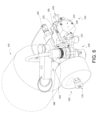
- FIGs. 6 and 8 illustrates another exemplary pressure relief shipping adapter 100 and a bottle head assembly 110 coupled to a container 105, according to certain embodiments.
- the pressure relief shipping adapter 100 may be configured to reduce the internal pressure of the container 105 to a predetermined value.
- the container 105 may be a pressure vessel configured to store a gas at a predetermined pressure.
- the container 105 may contain a volume of oxygen gas.
- the container 105 may be any suitable size, height, shape, and combinations thereof.
- the container 105 may generally be a cylindrical tank.
- the container 105 may comprise any suitable materials configured to withstand a predetermined internal pressure.
- the suitable materials may be metals, nonmetals, composites, and any combinations thereof.
- a bottle head assembly 110 may be disposed on top of and coupled to the container 105.
- the bottle head assembly 110 may be any suitable size, height, shape, and combinations thereof, and the bottle head assembly 110 may comprise any suitable materials.
- the suitable materials may be metals, nonmetals, composites, polymers, and any combinations thereof.
- the pressure relief shipping adapter 100 may be coupled to the container 105 through the bottle head assembly 110.
- the bottle head assembly 110 may be configured to seal the container 105, to pressurize the container 105, to depressurize the container 105, and any combinations thereof.
- the bottle head assembly 110 may comprise a servicing port 200 and a mechanical switch 205.
- the servicing port 200 may be disposed about any suitable location on the bottle head assembly 110.
- the servicing port 200 may be configured to couple to an external source and allow the flow of a gas (for example, oxygen), into the interior of the container 105.
- the servicing port 200 may be configured to only allow the flow of the gas one way, such as into the container 105.
- the mechanical switch 205 may be disposed near a top end 210 of the bottle head assembly 110. As shown, the mechanical switch 205 may be coupled to opposing sides of the bottle head assembly 110 near the top end 210 so as to be at least partially disposed around the bottle head assembly 110. In other embodiments, the mechanical switch 205 may be disposed about any suitable location on the bottle head assembly 110. The mechanical switch 205 may be configured to actuate between a first position and a second position, wherein switching between the first position and the second position may subsequently affect other components of the bottle head assembly 110. In embodiments, the mechanical switch 205 may be any suitable size, height, shape, and combinations thereof. The mechanical switch 205 may comprise any suitable materials such as metals, nonmetals, composites, and any combinations thereof.
- the mechanical switch 205 may comprise a lateral bar 215, a set of coupling bars 220, and a set of hinges 225.
- the set of coupling bars 220 may be disposed at opposite sides of the lateral bar 215.
- the set of coupling bars 220 may be perpendicular to the lateral bar 215.
- Each of the hinges 225 may be disposed at distal ends of each of the coupling bars 220 opposite from where the coupling bars 220 are connected to the lateral bar 215.
- the set of hinges 225 may couple the distal ends of the set of coupling bars 220 to the top end 210 of the bottle head assembly 110 and may provide a means of rotation for the mechanical switch 205, wherein the mechanical switch 205 may rotate about the set of hinges 225.
- the mechanical switch 205 may rotate any suitable degree range from the first position to the second position. In embodiments, the mechanical switch 205 may rotate within a degree range from about 0° to about 270°.
- the pressure relief shipping adapter 100 may be coupled to the bottle head assembly 110 and may interact with components of the bottle head assembly 110. As previously described, the pressure relief shipping adapter 100 may be configured to reduce the internal pressure of the container 105 to a predetermined value.
- the pressure relief shipping adapter 100 may comprise a body 230, a pressure relief valve 235, and a set of protrusions 250.
- the body 230 may be any suitable size, height, shape, and combinations thereof.
- the body 230 may comprise any suitable materials such as metals, nonmetals, composites, and any combinations thereof.
- the body 230 may be configured to house, contain, accommodate, and any combinations thereof any of the other components of the pressure relief shipping adapter 100 and/or of the bottle head assembly 110.
- the body 230 may comprise a first portion 255.
- the first portion 255 of the body 230 may generally be cylindrical in shape and may comprise a through-bore (as schematically illustrated in FIGs. 3 , 7B , and 8 ).
- the pressure relief valve 235 may be disposed about the first portion 255 of the body 230. As disclosed, the pressure relief valve 235 may be disposed about one end of the through-bore of the first portion 255, wherein the bottle head assembly 110 may be coupled to the opposing end of the through-bore. Without limitations, any suitable pressure relief valve may be used as the disclosed pressure relief valve 235. In embodiments, the pressure relief valve 235 may be set to a predetermined threshold value. The pressure relief valve 235 may be operable to reduce an internal pressure of the container 105 to the predetermined value of the pressure relief valve 235, based, at least in part, on the operation of the mechanical switch 205.
- the pressure relief shipping adapter 100 may comprise a first bore 240 and an interlocking component 245.
- the body 230 may comprise a second portion 260 disposed adjacent to the first portion 255.
- second portion 260 may generally have a rectangular shape.
- the first bore 240 may be disposed about the second portion 260 of the body 230, wherein the direction of the first bore 240 may be perpendicular to a central axis of the bottle head assembly 110.
- the first bore 240 may fully extend through the second portion 260.
- the first bore 240 may not be fully enclosed but may be partially open.
- the radial gap 265 may have a uniform arc length along the length of the radial gap 265, wherein the arc length is the distance between two opposing points along a section of a curve (for example, the portion of the second portion 260 designated as the radial gap 265).
- the arc length may be greater than the arc length along the length of the radial gap 265.
- the central angle used to calculate the arc length at the ends 270 may be greater than the central angle used to calculate the arc length along the length of the radial gap 265.
- the arc length of the first end 270a may be determined, at least in part, on the first point 275a, and the arc length of the second end 270b may be determined, at least in part, on the second point 275b.
- the arc lengths of the first end 270a and the second end 270b may be disposed in opposing tangential directions from each other.
- the first bore 240 may be configured to receive and at least partially contain the interlocking component 245.
- the interlocking component 245 may be any suitable size, height, shape, and combinations thereof.
- the interlocking component 245 may generally be in the shape of a rod or an elongated cylinder.
- the interlocking component 245 may comprise any suitable materials such as metals, nonmetals, composites, and any combinations thereof.
- the interlocking component 245 may be configured to interact with the mechanical switch 205 of the bottle head assembly 110.
- the interlocking component 245 may comprise a first tab 280a and a second tab 280b (collectively referred to herein as the "tabs 280"). Both the first tab 280a and the second tab 280b may be structures disposed along the length of the interlocking component 245 and extend outwards from the interlocking component 245. In embodiments, both tabs 280 may comprise the same size, height, shape, and combinations thereof. Both tabs 280 further may be disposed in the same direction parallel to each other. During operations, the interlocking component 245 may be configured to translate at least partially along the first bore 240, wherein the first tab 280a may be confined by the radial gap 265.
- the set of protrusions 250 may be utilized.
- the set of protrusions 250 may be disposed about the first portion 255 of the body 230.
- the set of protrusions 250 may comprise a hole 285 configured to receive a pin 288 to fix the pressure relief shipping adapter 100 to the bottle head assembly 110.
- the hole 285 may be located at the same position on each of the protrusions 250 to where there is a single, concentric hole as hole 285.
- a portion of the bottle head assembly 110 may be disposed between the set of protrusions 250, wherein that portion may also have a hole.
- the hole of the portion of the bottle head assembly 110 may be aligned with the hole 285, wherein the pin 288 may be disposed through the hole 285 and the hole in the portion of the bottle head assembly 110.
- any suitable fasteners may be used with or in replacement of the pin 288 to secure the set of protrusions 250 to the portion of the bottle head assembly 110, thereby coupling the pressure relief shipping adapter 100 to the bottle head assembly 110.
- FIG. 3 illustrates a side view of the pressure relief shipping adapter 100, according to certain embodiments.
- a bore 300 may be defined as the through-channel of the first portion 255 of the body 230 along a corresponding longitudinal axis of body 230.
- the pressure relief valve 235 may be disposed at one end of the bore 300 and the bottle head assembly 110 may be coupled to the opposite end of the bore 300.
- the through-channel defining the bore 300 may comprise a through-bore having a uniform cross-sectional shape and area taken along the full length of the corresponding longitudinal axis.
- the through-channel defining the bore 300 may not have a uniform cross-sectional shape or uniform cross-sectional area taken along the full length of the corresponding longitudinal axis.
- valve depressor 305 disposed within the bore 300 configured to actuate a valve (shown on FIGs. 5 , 7A , and 8 ) on the bottle head assembly 110.
- the valve depressor 305 may be disposed at any suitable position along the length of the bore 300.
- the valve depressor 305 may be disposed about the middle of the bore 300, near one end of the bore 300, or near the opposing end of the bore 300.
- the valve depressor 305 may be any suitable size, height, shape, and combinations thereof.
- the valve depressor 305 may generally comprise a circular shape with one or more extensions extending outwards towards a wall defining the bore 300.
- the valve depressor 305 may further comprise any suitable materials such as metals, nonmetals, composites, and any combinations thereof. During operations, a force may be applied to push the valve of the bottle head assembly 110 into the valve depressor 305 to open a channel providing communication from within the container 105 (referring to FIGs. 1 , 5 , and 8 ) to outside the container 105, wherein this communication may provide gas to flow out of the container 105.
- FIGs. 4A-4B illustrate perspective views of the pressure relief shipping adapter 100 coupled to the bottle head assembly 110 in different positions, according to certain embodiments.
- FIG. 4A illustrates the exemplary pressure relief shipping adapter 100 in a first position
- FIG. 4B illustrates the exemplary pressure relief shipping adapter 100 in a second position, according to certain embodiments provided with an interlocking arrangement illustrated in FIGs. 4A and 4B .
- the pressure relief shipping adapter 100 may be coupled to the bottle head assembly 110 while in the first position, wherein the first tab 280a of the interlocking component 245 may be disposed in the first end 270a of the radial gap 265.
- the second tab 280b may be disposed adjacent to the body 230 between the pressure relief shipping adapter 100 and the bottle head assembly 110.
- the pressure relief shipping adapter 100 may be at the first position
- the mechanical switch 205 may be at the first position.
- the first position of the mechanical switch 205 may be where the mechanical switch 205 is disposed against a surface of the bottle head assembly 110 perpendicular to the top end 210.
- the mechanical switch 205 may be actuated to rotate about the set of hinges 225 (referring to FIG. 2 ) to a second position, wherein as the mechanical switch 205 rotates, there is no physical interference from the interlocking component 245.
- a pin 410 may be actuated (for example, pushed or pulled) in order to remove any inhibiting structure of the mechanical switch 205.
- rotating the mechanical switch 205 from the first position to the second position may actuate the valve 510 (as illustrated in FIGs. 5 and 8 ) of the bottle head assembly 110 to vent any contents held within the container 105 (referring to FIGs. 1 and 8 ).
- the pressure relief shipping adapter 100 may be operable to change to the second position, as illustrated in FIG. 4B .
- the first tab 280a may rotate about a central axis of the interlocking component 245 to align with the length of the radial gap 265. Once aligned, the first tab 280a may translate along the length of the radial gap 265. After translating along the length of the radial gap 265, the first tab 280a may be rotated along the arc length of the second end 270b of the radial gap 265.
- a front surface 400 of both the tabs 280 may convey information to an operator.
- the front surface 400 may indicate to the operator that the container 105 associated with the pressure relief shipping adapter 100 is not ready for transportation or shipment between locations.
- the container 105 may not be ready when the internal pressure of the container 105 has not been vented or reduced to a predetermined value.
- the front surface 400 may comprise any suitable data, such as numbers and/or letters, a specific color, or combinations thereof.
- a back surface 405 of both the tabs 280 may indicate to the operator that the container 105 associated with the pressure relief shipping adapter 100 is ready for transportation or shipment between locations. Similar to the front surface 400, the back surface 405 may comprise any suitable data, such as numbers and/or letters, a specific color, or combinations thereof.
- FIGs. 5 and 8 illustrate a cross-sectional views of the pressure relief shipping adapter 100 coupled to the bottle head assembly 110.
- the pressure relief valve 235 may be disposed at a first end 500 of the bore 300 and the bottle head assembly 110 may be coupled to a second end 505 of the bore 300 opposite from the first end 500.
- a valve 510 of the bottle head assembly 110 may be at least partially inserted into the second bore 300.
- the valve 510 may be operable to vent and/or relieve the contents of the container 105 as the bottle head assembly 110 is placed in fluid communication with the interior of the container 105.
- the valve 510 may be actuated when depressed by an external structure.
- valve 510 As the valve 510 is inserted into the second bore 300, the valve 510 may be actuated by the valve depressor 305. In other embodiments, the valve 510 may be disposed adjacent to and abut the valve depressor 305, when inserted into the second bore 300, and there may be actuation through the mechanical switch 205 (such as illustrated in FIGs. 2 and 6 ). As illustrated, there may be one or more seals 515 disposed in the bore 300 configured to seal the valve 510 or the bottle head assembly 110 against the pressure relief shipping adapter 100. By way of example and not limitation, FIG. 5 illustrates a single seal 515. By way of example and not limitation, FIG. 8 illustrates a multiple seals 515.
- each of the seals 515 may be provided with one or more grooves to receive the corresponding seal.
- the seals 515 may prevent any gas released by the valve 510 from escaping through the coupling of the bottle head assembly 110 to the pressure relief shipping adapter 100.
- at least a portion of the released gas from the valve 510 into the bore 30 may be expelled from the pressure relief shipping adapter 100 through the pressure relief valve 235, wherein the pressure relief valve 235 may provide communication to an external environment until the predetermined threshold value of the pressure relief valve 235 is met.
- pressure relief valve 235 may experience fluctuating conditions of rapid and/or repeated opening and closing.
- valve fluctuation or instability can generate undesirable heat, increase mechanical and component stresses, and/or decrease operating lifespans.
- an increased volume of bore 300 can mitigate or prevent valve instability and/or oscillation, such as by providing a damping volume for an intermediate gas volume in the pressure relief shipping adapter 100.
- FIGs. 6-8 illustrate certain embodiments of pressure relief shipping adapter 100 provided with an internal chamber 290 to provide such an increased volume of bore 300.
- internal chamber 290 may comprise a first section corresponding to first portion 255 of body 230, which may be provided with an initial cross-sectional shape and/or area of bore 300.
- internal chamber 290 may comprise a second section corresponding to a transitional portion 310, which may be provided to increase an initial cross-sectional area of bore 300 at first portion 255 to a larger cross-sectional area of internal chamber 290 at a third section 315.
- internal chamber 290 may comprise a third section 315 comprising a larger internal cross-sectional area and/or internal volume than provided at first portion 255 or transitional portion 310.
- the third section may comprise an outlet 295.
- Pressure relief valve 235 may be coupled to outlet 295.
- first portion 255 may comprise a cylindrical volume
- transitional portion 310 may comprise a truncated cone volume
- third section 315 may comprise a cylindrical volume.
- third section 315 may comprise a larger internal and/or external volume than first portion 255 or transitional portion 310.
- references in the appended claims to an apparatus or system or a component of an apparatus or system being adapted to, arranged to, capable of, configured to, enabled to, operable to, or operative to perform a particular function encompasses that apparatus, system, component, whether or not it or that particular function is activated, turned on, or unlocked, as long as that apparatus, system, or component is so adapted, arranged, capable, configured, enabled, operable, or operative. Additionally, although this disclosure describes or illustrates particular embodiments as providing particular advantages, particular embodiments may provide none, some, or all of these advantages.
Landscapes
- Engineering & Computer Science (AREA)
- General Engineering & Computer Science (AREA)
- Mechanical Engineering (AREA)
- Filling Or Discharging Of Gas Storage Vessels (AREA)
Abstract
Description
- This disclosure generally relates to pressure reduction devices, and more specifically, to a pressure relief shipping adapter for reducing an internal pressure of a container prior to transportation.
- Pressurized containers of oxygen gas are supplied to aircraft to be used in urgent situations. There is currently no tool, system, or method capable of verifying a safe condition of contents of these containers by reducing the internal pressure to a predetermined threshold value prior to transportation to the aircraft.
- In particular embodiments, a pressure relief shipping adapter is disclosed that includes: a body including a first portion, a transitional portion, and a second portion, wherein the transitional portion is disposed between the first portion and the second portion, wherein: the first portion includes: a set of protrusions and a hole disposed through the set of protrusions; and an inlet disposed at a first end of the body; the second portion includes an outlet disposed at a second end of the body, wherein the outlet is concentric with the inlet; an internal chamber within the body including a first section, a second section, and a third section, wherein the first section corresponds to the first portion of the body, wherein the second section corresponds to the transitional portion of the body, and wherein the third section corresponds to the second portion of the body; and a pressure relief valve disposed at the second end of the body and coupled to the outlet.
- In particular embodiments, which may combine the features of some or all of the above embodiments, a pressure relief shipping adapter further includes a valve depressor disposed within the internal chamber. In particular embodiments, which may combine the features of some or all of the above embodiments, a pressure relief shipping adapter further includes a first seal and a second seal disposed within the internal chamber proximate to the inlet. In particular embodiments, which may combine the features of some or all of the above embodiments, a pressure relief shipping adapter further includes a first groove configured to receive the first seal and a second groove configured to receive the second seal.
- In particular embodiments, which may combine the features of some or all of the above embodiments, the third section includes a larger volume than the first section. In particular embodiments, which may combine the features of some or all of the above embodiments, the second portion includes a larger diameter than the first portion. In particular embodiments, which may combine the features of some or all of the above embodiments, the first section includes a cylindrical volume, wherein the second section includes a truncated cone volume, and wherein the third section includes a cylindrical volume.
- In particular embodiments, which may combine the features of some or all of the above embodiments, a method of using a pressure relief shipping adapter is disclosed, including: coupling the pressure relief shipping adapter to a bottle head assembly, wherein the bottle head assembly is coupled to a container containing a pressurized gas; reducing an internal pressure of the container by displacing a valve of the bottle head assembly into a valve depressor, the valve depressor disposed within an internal chamber defined by a body of the pressure relief shipping adapter; and discharging the pressurized gas from the container, through the body of the pressure relief shipping adapter, and out an outlet of the body.
- In particular embodiments, which may combine the features of some or all of the above embodiments, coupling the pressure relief shipping adapter to a bottle head assembly includes inserting a pin through a hole in a set of protrusions of the pressure shipping adapter. In particular embodiments, which may combine the features of some or all of the above embodiments, a method further includes aligning a hole of a portion of the bottle head assembly disposed between the set of protrusions with the hole of the set of protrusions to be concentric.
- In particular embodiments, which may combine the features of some or all of the above embodiments, the valve of the bottle head assembly is sealed within the internal chamber of the pressure relief shipping adapter. In particular embodiments, which may combine the features of some or all of the above embodiments, a pressure relief valve is disposed at an end of the body of the pressure relief shipping adapter, wherein the internal pressure of the container is reduced by venting the pressurized gas through the pressure relief valve.
- In particular embodiments, which may combine the features of some or all of the above embodiments, a container pressure system is disclosed that includes: a bottle head assembly coupled to a container, wherein the container includes a pressurized gas and the bottle head assembly includes a valve; and a pressure relief shipping adapter coupled to the bottle head assembly, the pressure relief shipping adapter including: a body including a first portion, a transitional portion, and a second portion, wherein the transitional portion is disposed between the first portion and the second portion, wherein: the first portion includes: a set of protrusions and a hole disposed through the set of protrusions; and an inlet disposed at a first end of the body; the second portion includes an outlet disposed at a second end of the body, wherein the outlet is concentric with the inlet; an internal chamber within the body including a first section, a second section, and a third section, wherein the first section corresponds to the first portion of the body, wherein the second section corresponds to the transitional portion of the body, and wherein the third section corresponds to the second portion of the body; and a pressure relief valve disposed at the second end of the body and coupled to the outlet.
- In particular embodiments, which may combine the features of some or all of the above embodiments, the first section includes a cylindrical volume, wherein the second section includes a truncated cone volume, and wherein the third section includes a cylindrical volume. In particular embodiments, which may combine the features of some or all of the above embodiments, the pressure relief shipping adapter further includes a valve depressor disposed within the internal chamber, and wherein the valve of the bottle head assembly is inserted into a first end of the body via the inlet. In particular embodiments, which may combine the features of some or all of the above embodiments, the pressure relief shipping adapter further includes a first seal and a second seal disposed within the internal chamber proximate to the inlet. In particular embodiments, which may combine the features of some or all of the above embodiments, the pressure relief shipping adapter further includes a first groove configured to receive the first seal and a second groove configured to receive the second seal.
- In particular embodiments, which may combine the features of some or all of the above embodiments, the third section includes a larger volume than the first section. In particular embodiments, which may combine the features of some or all of the above embodiments, the second portion includes a larger diameter than the first portion. In particular embodiments, which may combine the features of some or all of the above embodiments, a hole of a portion of the bottle head assembly disposed between the set of protrusions is aligned with the hole of the set of protrusions to be concentric and to receive a pin.
- To assist in understanding the present disclosure, reference is now made to the following description taken in conjunction with the accompanying drawings, in which:
-
FIG. 1 illustrates an example pressure relief shipping adapter and an example container, according to certain embodiments; -
FIG. 2 illustrates an example perspective view of the pressure relief shipping adapter inFIG. 1 coupled to an example bottle head assembly, according to certain embodiments; -
FIG. 3 illustrates an example side view of the pressure relief shipping adapter inFIG. 1 , according to certain embodiments; -
FIG. 4A illustrates an example perspective view of the pressure relief shipping adapter inFIG. 1 in a first position, according to certain embodiments; -
FIG. 4B illustrates an example perspective view of the pressure relief shipping adapter inFIG. 1 in a second position, according to certain embodiments; -
FIG. 5 illustrates an example cross-section view of the pressure relief shipping adapter inFIG. 1 coupled to the example bottle head assembly inFIG. 2 , according to certain embodiments; -
FIG. 6 illustrates a perspective view of another example pressure relief shipping adapter coupled to an example bottle head assembly, according to certain embodiments; -
FIG. 7A illustrates an example cross-section view of the pressure relief shipping adapter inFIG. 6 , according to certain embodiments; -
FIG. 7B illustrates an example perspective view of the pressure relief shipping adapter inFIG. 6 , according to certain embodiments; and -
FIG. 8 illustrates an example cross-section view of the pressure relief shipping adapter inFIG. 6 coupled to the example bottle head assembly, according to certain embodiments. - To facilitate a better understanding of the present disclosure, the following examples of certain embodiments are given. The following examples are not to be read to limit or define the scope of the disclosure. Embodiments of the present disclosure and its advantages are best understood by referring to
FIGs. 1 through 8 , where like numbers are used to indicate like and corresponding parts. - Described herein are various systems, tools, and methods that provide for a structure to reduce the pressure within a pressurized container of oxygen gas prior to shipping and/or transportation.
FIGs. 1 and2 illustrates a perspective view of an exemplary pressurerelief shipping adapter 100 and abottle head assembly 110 coupled to acontainer 105, according to certain embodiments.FIGs. 6 and8 illustrates another exemplary pressurerelief shipping adapter 100 and abottle head assembly 110 coupled to acontainer 105, according to certain embodiments. The pressurerelief shipping adapter 100 according to one or more certain embodiments may be configured to reduce the internal pressure of thecontainer 105 to a predetermined value. In one or more embodiments, thecontainer 105 may be a pressure vessel configured to store a gas at a predetermined pressure. Without limitations, thecontainer 105 may contain a volume of oxygen gas. In embodiments, thecontainer 105 may be any suitable size, height, shape, and combinations thereof. Without limitations, thecontainer 105 may generally be a cylindrical tank. Thecontainer 105 may comprise any suitable materials configured to withstand a predetermined internal pressure. Without limitations, the suitable materials may be metals, nonmetals, composites, and any combinations thereof. - As illustrated herein, a
bottle head assembly 110 may be disposed on top of and coupled to thecontainer 105. In embodiments, there may be an opening through the top of thecontainer 105 to allow for fluid communication between an interior and an exterior of thecontainer 105 of a given gas. As thebottle head assembly 110 is coupled to the top of thecontainer 105, the interior of thecontainer 105 may effectively be sealed. In embodiments, thebottle head assembly 110 may be any suitable size, height, shape, and combinations thereof, and thebottle head assembly 110 may comprise any suitable materials. Without limitations, the suitable materials may be metals, nonmetals, composites, polymers, and any combinations thereof. In one or more embodiments, the pressurerelief shipping adapter 100 may be coupled to thecontainer 105 through thebottle head assembly 110. - The
bottle head assembly 110 may be configured to seal thecontainer 105, to pressurize thecontainer 105, to depressurize thecontainer 105, and any combinations thereof. In certain embodiments, thebottle head assembly 110 may comprise aservicing port 200 and amechanical switch 205. Theservicing port 200 may be disposed about any suitable location on thebottle head assembly 110. Theservicing port 200 may be configured to couple to an external source and allow the flow of a gas (for example, oxygen), into the interior of thecontainer 105. Theservicing port 200 may be configured to only allow the flow of the gas one way, such as into thecontainer 105. There may be other suitable components, such as valves, used within thebottle head assembly 110 to preserve the gas within thecontainer 105. As the volume of gas flowing into thecontainer 105 increases, the pressure within thecontainer 105 may increase accordingly. - As illustrated in
FIGs. 2 and6 , themechanical switch 205 may be disposed near atop end 210 of thebottle head assembly 110. As shown, themechanical switch 205 may be coupled to opposing sides of thebottle head assembly 110 near thetop end 210 so as to be at least partially disposed around thebottle head assembly 110. In other embodiments, themechanical switch 205 may be disposed about any suitable location on thebottle head assembly 110. Themechanical switch 205 may be configured to actuate between a first position and a second position, wherein switching between the first position and the second position may subsequently affect other components of thebottle head assembly 110. In embodiments, themechanical switch 205 may be any suitable size, height, shape, and combinations thereof. Themechanical switch 205 may comprise any suitable materials such as metals, nonmetals, composites, and any combinations thereof. - In certain embodiments, the
mechanical switch 205 may comprise alateral bar 215, a set of coupling bars 220, and a set ofhinges 225. The set of coupling bars 220 may be disposed at opposite sides of thelateral bar 215. In embodiments the set of coupling bars 220 may be perpendicular to thelateral bar 215. Each of thehinges 225 may be disposed at distal ends of each of the coupling bars 220 opposite from where the coupling bars 220 are connected to thelateral bar 215. The set ofhinges 225 may couple the distal ends of the set ofcoupling bars 220 to thetop end 210 of thebottle head assembly 110 and may provide a means of rotation for themechanical switch 205, wherein themechanical switch 205 may rotate about the set ofhinges 225. Without limitations, themechanical switch 205 may rotate any suitable degree range from the first position to the second position. In embodiments, themechanical switch 205 may rotate within a degree range from about 0° to about 270°. - The pressure
relief shipping adapter 100 may be coupled to thebottle head assembly 110 and may interact with components of thebottle head assembly 110. As previously described, the pressurerelief shipping adapter 100 may be configured to reduce the internal pressure of thecontainer 105 to a predetermined value. The pressurerelief shipping adapter 100 may comprise abody 230, apressure relief valve 235, and a set ofprotrusions 250. In embodiments, thebody 230 may be any suitable size, height, shape, and combinations thereof. Thebody 230 may comprise any suitable materials such as metals, nonmetals, composites, and any combinations thereof. Thebody 230 may be configured to house, contain, accommodate, and any combinations thereof any of the other components of the pressurerelief shipping adapter 100 and/or of thebottle head assembly 110. Thebody 230 may comprise afirst portion 255. Thefirst portion 255 of thebody 230 may generally be cylindrical in shape and may comprise a through-bore (as schematically illustrated inFIGs. 3 ,7B , and8 ). - The
pressure relief valve 235 may be disposed about thefirst portion 255 of thebody 230. As disclosed, thepressure relief valve 235 may be disposed about one end of the through-bore of thefirst portion 255, wherein thebottle head assembly 110 may be coupled to the opposing end of the through-bore. Without limitations, any suitable pressure relief valve may be used as the disclosedpressure relief valve 235. In embodiments, thepressure relief valve 235 may be set to a predetermined threshold value. Thepressure relief valve 235 may be operable to reduce an internal pressure of thecontainer 105 to the predetermined value of thepressure relief valve 235, based, at least in part, on the operation of themechanical switch 205. - In certain embodiments, such as illustrated in
FIGs. 2-5 , the pressurerelief shipping adapter 100 may comprise afirst bore 240 and aninterlocking component 245. In certain embodiments, such as illustrated inFIGs. 2-5 , thebody 230 may comprise asecond portion 260 disposed adjacent to thefirst portion 255. In embodiments,second portion 260 may generally have a rectangular shape. - In certain embodiments, such as illustrated in
FIGs. 2-5 , thefirst bore 240 may be disposed about thesecond portion 260 of thebody 230, wherein the direction of thefirst bore 240 may be perpendicular to a central axis of thebottle head assembly 110. Thefirst bore 240 may fully extend through thesecond portion 260. In embodiments, thefirst bore 240 may not be fully enclosed but may be partially open. As illustrated inFIGs. 4A-4B , there may be aradial gap 265 disposed through a portion of thesecond portion 260 of thebody 230 that exposes thefirst bore 240 to an external environment. Theradial gap 265 may have a uniform arc length along the length of theradial gap 265, wherein the arc length is the distance between two opposing points along a section of a curve (for example, the portion of thesecond portion 260 designated as the radial gap 265). At each of afirst end 270a and asecond end 270b (collectively referred to herein as the "ends 270") of theradial gap 265, the arc length may be greater than the arc length along the length of theradial gap 265. For example, the central angle used to calculate the arc length at the ends 270 may be greater than the central angle used to calculate the arc length along the length of theradial gap 265. In embodiments, the arc length at both of the ends 270 may be equivalent. While the arc length at the ends 270 may be greater than that along the length of theradial gap 265, each of thefirst end 270a and thesecond end 270b may share a common point used in determining the arc length with the section along the length of theradial gap 265. For example, the arc length along the length of theradial gap 265 may be determined from afirst point 275a and a second point 275b of a portion of the circumference of the first portion. The arc length of thefirst end 270a may be determined, at least in part, on thefirst point 275a, and the arc length of thesecond end 270b may be determined, at least in part, on the second point 275b. As such, the arc lengths of thefirst end 270a and thesecond end 270b may be disposed in opposing tangential directions from each other. - In certain embodiments, such as illustrated in
FIGs. 2-5 , and as illustrated inFIG. 2 , thefirst bore 240 may be configured to receive and at least partially contain the interlockingcomponent 245. In embodiments, the interlockingcomponent 245 may be any suitable size, height, shape, and combinations thereof. The interlockingcomponent 245 may generally be in the shape of a rod or an elongated cylinder. The interlockingcomponent 245 may comprise any suitable materials such as metals, nonmetals, composites, and any combinations thereof. The interlockingcomponent 245 may be configured to interact with themechanical switch 205 of thebottle head assembly 110. The interlockingcomponent 245 may comprise afirst tab 280a and asecond tab 280b (collectively referred to herein as the "tabs 280"). Both thefirst tab 280a and thesecond tab 280b may be structures disposed along the length of the interlockingcomponent 245 and extend outwards from the interlockingcomponent 245. In embodiments, both tabs 280 may comprise the same size, height, shape, and combinations thereof. Both tabs 280 further may be disposed in the same direction parallel to each other. During operations, the interlockingcomponent 245 may be configured to translate at least partially along thefirst bore 240, wherein thefirst tab 280a may be confined by theradial gap 265. - To couple the pressure
relief shipping adapter 100 to thebottle head assembly 110, the set ofprotrusions 250 may be utilized. In embodiments, as illustrated inFIGs. 2 ,3 ,6 , and7B , the set ofprotrusions 250 may be disposed about thefirst portion 255 of thebody 230. The set ofprotrusions 250 may comprise ahole 285 configured to receive apin 288 to fix the pressurerelief shipping adapter 100 to thebottle head assembly 110. Thehole 285 may be located at the same position on each of theprotrusions 250 to where there is a single, concentric hole ashole 285. In embodiments, a portion of thebottle head assembly 110 may be disposed between the set ofprotrusions 250, wherein that portion may also have a hole. The hole of the portion of thebottle head assembly 110 may be aligned with thehole 285, wherein thepin 288 may be disposed through thehole 285 and the hole in the portion of thebottle head assembly 110. In one or more embodiments, any suitable fasteners may be used with or in replacement of thepin 288 to secure the set ofprotrusions 250 to the portion of thebottle head assembly 110, thereby coupling the pressurerelief shipping adapter 100 to thebottle head assembly 110. -
FIG. 3 illustrates a side view of the pressurerelief shipping adapter 100, according to certain embodiments. As illustrated, abore 300 may be defined as the through-channel of thefirst portion 255 of thebody 230 along a corresponding longitudinal axis ofbody 230. As previously disclosed, in certain embodiments, such as illustrated inFIGs. 2 and8 , thepressure relief valve 235 may be disposed at one end of thebore 300 and thebottle head assembly 110 may be coupled to the opposite end of thebore 300. In certain embodiments, such as illustrated inFIG. 2 without limitations, the through-channel defining thebore 300 may comprise a through-bore having a uniform cross-sectional shape and area taken along the full length of the corresponding longitudinal axis. In certain embodiments, such as illustrated inFIGs. 7A and8 without limitations, the through-channel defining thebore 300 may not have a uniform cross-sectional shape or uniform cross-sectional area taken along the full length of the corresponding longitudinal axis. - There may be a
valve depressor 305 disposed within thebore 300 configured to actuate a valve (shown onFIGs. 5 ,7A , and8 ) on thebottle head assembly 110. In embodiments, thevalve depressor 305 may be disposed at any suitable position along the length of thebore 300. Thevalve depressor 305 may be disposed about the middle of thebore 300, near one end of thebore 300, or near the opposing end of thebore 300. In embodiments, thevalve depressor 305 may be any suitable size, height, shape, and combinations thereof. Thevalve depressor 305 may generally comprise a circular shape with one or more extensions extending outwards towards a wall defining thebore 300. Thevalve depressor 305 may further comprise any suitable materials such as metals, nonmetals, composites, and any combinations thereof. During operations, a force may be applied to push the valve of thebottle head assembly 110 into thevalve depressor 305 to open a channel providing communication from within the container 105 (referring toFIGs. 1 ,5 , and8 ) to outside thecontainer 105, wherein this communication may provide gas to flow out of thecontainer 105. - In certain embodiments, one or more interlocking systems may be provided to prevent inadvertent actuation of gas flow.
FIGs. 4A-4B illustrate perspective views of the pressurerelief shipping adapter 100 coupled to thebottle head assembly 110 in different positions, according to certain embodiments.FIG. 4A illustrates the exemplary pressurerelief shipping adapter 100 in a first position, andFIG. 4B illustrates the exemplary pressurerelief shipping adapter 100 in a second position, according to certain embodiments provided with an interlocking arrangement illustrated inFIGs. 4A and4B . As illustrated, the pressurerelief shipping adapter 100 may be coupled to thebottle head assembly 110 while in the first position, wherein thefirst tab 280a of the interlockingcomponent 245 may be disposed in thefirst end 270a of theradial gap 265. Thesecond tab 280b may be disposed adjacent to thebody 230 between the pressurerelief shipping adapter 100 and thebottle head assembly 110. At this stage, the pressurerelief shipping adapter 100 may be at the first position, and themechanical switch 205 may be at the first position. The first position of themechanical switch 205 may be where themechanical switch 205 is disposed against a surface of thebottle head assembly 110 perpendicular to thetop end 210. During operations, themechanical switch 205 may be actuated to rotate about the set of hinges 225 (referring toFIG. 2 ) to a second position, wherein as themechanical switch 205 rotates, there is no physical interference from the interlockingcomponent 245. - In certain embodiments, such as illustrated in
FIGs. 4A ,4B , and6 , before themechanical switch 205 is rotated, apin 410 may be actuated (for example, pushed or pulled) in order to remove any inhibiting structure of themechanical switch 205. In embodiments, rotating themechanical switch 205 from the first position to the second position may actuate the valve 510 (as illustrated inFIGs. 5 and8 ) of thebottle head assembly 110 to vent any contents held within the container 105 (referring toFIGs. 1 and8 ). - Returning to the exemplary embodiments of
FIGs. 4A-4B provided with a specific interlocking arrangement, without limitations, once themechanical switch 205 is in the second position, the pressurerelief shipping adapter 100 may be operable to change to the second position, as illustrated inFIG. 4B . Thefirst tab 280a may rotate about a central axis of the interlockingcomponent 245 to align with the length of theradial gap 265. Once aligned, thefirst tab 280a may translate along the length of theradial gap 265. After translating along the length of theradial gap 265, thefirst tab 280a may be rotated along the arc length of thesecond end 270b of theradial gap 265. As thefirst tab 280a rotates and translates, thesecond tab 280b rotates and translates accordingly as they are connected through the interlockingcomponent 245. This may be designated as the second position of the exemplarypressure shipping adapter 100 featuring an interlocking arrangement illustrated inFIGs. 4A-4B . Prior to rotation, afront surface 400 of both the tabs 280 may convey information to an operator. For example, thefront surface 400 may indicate to the operator that thecontainer 105 associated with the pressurerelief shipping adapter 100 is not ready for transportation or shipment between locations. Thecontainer 105 may not be ready when the internal pressure of thecontainer 105 has not been vented or reduced to a predetermined value. Without limitations, thefront surface 400 may comprise any suitable data, such as numbers and/or letters, a specific color, or combinations thereof. After rotation, aback surface 405 of both the tabs 280 may indicate to the operator that thecontainer 105 associated with the pressurerelief shipping adapter 100 is ready for transportation or shipment between locations. Similar to thefront surface 400, theback surface 405 may comprise any suitable data, such as numbers and/or letters, a specific color, or combinations thereof. -
FIGs. 5 and8 illustrate a cross-sectional views of the pressurerelief shipping adapter 100 coupled to thebottle head assembly 110. As illustrated, thepressure relief valve 235 may be disposed at afirst end 500 of thebore 300 and thebottle head assembly 110 may be coupled to asecond end 505 of thebore 300 opposite from thefirst end 500. Avalve 510 of thebottle head assembly 110 may be at least partially inserted into thesecond bore 300. Thevalve 510 may be operable to vent and/or relieve the contents of thecontainer 105 as thebottle head assembly 110 is placed in fluid communication with the interior of thecontainer 105. In embodiments, thevalve 510 may be actuated when depressed by an external structure. As thevalve 510 is inserted into thesecond bore 300, thevalve 510 may be actuated by thevalve depressor 305. In other embodiments, thevalve 510 may be disposed adjacent to and abut thevalve depressor 305, when inserted into thesecond bore 300, and there may be actuation through the mechanical switch 205 (such as illustrated inFIGs. 2 and6 ). As illustrated, there may be one ormore seals 515 disposed in thebore 300 configured to seal thevalve 510 or thebottle head assembly 110 against the pressurerelief shipping adapter 100. By way of example and not limitation,FIG. 5 illustrates asingle seal 515. By way of example and not limitation,FIG. 8 illustrates a multiple seals 515. In certain embodiments, each of theseals 515 may be provided with one or more grooves to receive the corresponding seal. Theseals 515 may prevent any gas released by thevalve 510 from escaping through the coupling of thebottle head assembly 110 to the pressurerelief shipping adapter 100. In embodiments, at least a portion of the released gas from thevalve 510 into the bore 30 may be expelled from the pressurerelief shipping adapter 100 through thepressure relief valve 235, wherein thepressure relief valve 235 may provide communication to an external environment until the predetermined threshold value of thepressure relief valve 235 is met. - In certain embodiments and under particular conditions,
pressure relief valve 235 may experience fluctuating conditions of rapid and/or repeated opening and closing. By way of example and not limitation, valve fluctuation or instability can generate undesirable heat, increase mechanical and component stresses, and/or decrease operating lifespans. In certain embodiments, an increased volume ofbore 300 can mitigate or prevent valve instability and/or oscillation, such as by providing a damping volume for an intermediate gas volume in the pressurerelief shipping adapter 100.FIGs. 6-8 illustrate certain embodiments of pressurerelief shipping adapter 100 provided with aninternal chamber 290 to provide such an increased volume ofbore 300. - By way of example and not limitation,
internal chamber 290 may comprise a first section corresponding tofirst portion 255 ofbody 230, which may be provided with an initial cross-sectional shape and/or area ofbore 300. By way of example and not limitation,internal chamber 290 may comprise a second section corresponding to atransitional portion 310, which may be provided to increase an initial cross-sectional area ofbore 300 atfirst portion 255 to a larger cross-sectional area ofinternal chamber 290 at athird section 315. By way of example and not limitation,internal chamber 290 may comprise athird section 315 comprising a larger internal cross-sectional area and/or internal volume than provided atfirst portion 255 ortransitional portion 310. In certain embodiments, the third section may comprise anoutlet 295.Pressure relief valve 235 may be coupled tooutlet 295. - In certain embodiments,
first portion 255 may comprise a cylindrical volume,transitional portion 310 may comprise a truncated cone volume, and/orthird section 315 may comprise a cylindrical volume. In certain embodiments,third section 315 may comprise a larger internal and/or external volume thanfirst portion 255 ortransitional portion 310. - The present disclosure may provide numerous advantages, such as the various technical advantages that have been described with respective to various embodiments and examples disclosed herein. Other technical advantages will be readily apparent to one skilled in the art from the following figures, descriptions, and claims. Moreover, while specific advantages have been enumerated in this disclosure, various embodiments may include all, some, or none of the enumerated advantages.
- Herein, "or" is inclusive and not exclusive, unless expressly indicated otherwise or indicated otherwise by context. Therefore, herein, "A or B" means "A, B, or both," unless expressly indicated otherwise or indicated otherwise by context. Moreover, "and" is both joint and several, unless expressly indicated otherwise or indicated otherwise by context. Therefore, herein, "A and B" means "A and B, jointly or severally," unless expressly indicated otherwise or indicated otherwise by context.
- Unless indicated to the contrary, the numerical parameters set forth in the specification and attached claims are approximations that may vary depending upon the desired properties sought to be obtained by the embodiments of the present disclosure. At the very least, and not as an attempt to limit the application of the doctrine of equivalents to the scope of the claim, each numerical parameter should at least be construed in light of the number of reported significant digits and by applying ordinary rounding techniques.
- The scope of this disclosure encompasses all changes, substitutions, variations, alterations, and modifications to the example embodiments described or illustrated herein that a person having ordinary skill in the art would comprehend. The scope of this disclosure is not limited to the example embodiments described or illustrated herein. Moreover, although this disclosure describes and illustrates respective embodiments herein as including particular components, elements, feature, functions, operations, or steps, any of these embodiments may include any combination or permutation of any of the components, elements, features, functions, operations, or steps described or illustrated anywhere herein that a person having ordinary skill in the art would comprehend. Furthermore, reference in the appended claims to an apparatus or system or a component of an apparatus or system being adapted to, arranged to, capable of, configured to, enabled to, operable to, or operative to perform a particular function encompasses that apparatus, system, component, whether or not it or that particular function is activated, turned on, or unlocked, as long as that apparatus, system, or component is so adapted, arranged, capable, configured, enabled, operable, or operative. Additionally, although this disclosure describes or illustrates particular embodiments as providing particular advantages, particular embodiments may provide none, some, or all of these advantages.
Claims (15)
- A pressure relief shipping adapter, comprising:a body comprising a first portion, a transitional portion, and a second portion, wherein the transitional portion is disposed between the first portion and the second portion, wherein:the first portion comprises:a set of protrusions and a hole disposed through the set of protrusions; andan inlet disposed at a first end of the body;the second portion comprises an outlet disposed at a second end of the body, wherein the outlet is concentric with the inlet;an internal chamber within the body comprising a first section, a second section, and a third section, wherein the first section corresponds to the first portion of the body, wherein the second section corresponds to the transitional portion of the body, and wherein the third section corresponds to the second portion of the body; anda pressure relief valve disposed at the second end of the body and coupled to the outlet.
- The pressure relief shipping adapter of claim 1, further comprising a valve depressor disposed within the internal chamber.
- The pressure relief shipping adapter of claim 1 or claim 2, further comprising a first seal and a second seal disposed within the internal chamber proximate to the inlet; and optionally or preferably further comprising a first groove configured to receive the first seal and a second groove configured to receive the second seal.
- The pressure relief shipping adapter of any preceding claim, wherein the third section comprises a larger volume than the first section.
- The pressure relief shipping adapter of any preceding claim, wherein the second portion comprises a larger diameter than the first portion.
- The pressure relief shipping adapter of any preceding claim, wherein the first section comprises a cylindrical volume, wherein the second section comprises a truncated cone volume, and wherein the third section comprises a cylindrical volume.
- A method of using a pressure relief shipping adapter, comprising:coupling the pressure relief shipping adapter to a bottle head assembly, wherein the bottle head assembly is coupled to a container containing a pressurized gas;reducing an internal pressure of the container by displacing a valve of the bottle head assembly into a valve depressor, the valve depressor disposed within an internal chamber defined by a body of the pressure relief shipping adapter; anddischarging the pressurized gas from the container, through the body of the pressure relief shipping adapter, and out an outlet of the body.
- The method of claim 7, wherein coupling the pressure relief shipping adapter to a bottle head assembly comprises inserting a pin through a hole in a set of protrusions of the pressure shipping adapter; and optionally further comprising aligning a hole of a portion of the bottle head assembly disposed between the set of protrusions with the hole of the set of protrusions to be concentric.
- The method of claim 7 or claim 8, wherein the valve of the bottle head assembly is sealed within the internal chamber of the pressure relief shipping adapter.
- The method of any of claims 7 to 9, wherein a pressure relief valve is disposed at an end of the body of the pressure relief shipping adapter, wherein the internal pressure of the container is reduced by venting the pressurized gas through the pressure relief valve.
- A container pressure system, comprising:a bottle head assembly coupled to a container, wherein the container comprises a pressurized gas and the bottle head assembly comprises a valve; anda pressure relief shipping adapter coupled to the bottle head assembly, the pressure relief shipping adapter comprising:a body comprising a first portion, a transitional portion, and a second portion, wherein the transitional portion is disposed between the first portion and the second portion, wherein:the first portion comprises:a set of protrusions and a hole disposed through the set of protrusions; andan inlet disposed at a first end of the body;the second portion comprises an outlet disposed at a second end of the body, wherein the outlet is concentric with the inlet;an internal chamber within the body comprising a first section, a second section, and a third section, wherein the first section corresponds to the first portion of the body, wherein the second section corresponds to the transitional portion of the body, and wherein the third section corresponds to the second portion of the body; anda pressure relief valve disposed at the second end of the body and coupled to the outlet.
- The container pressure system of claim 11, wherein the first section comprises a cylindrical volume, wherein the second section comprises a truncated cone volume, and wherein the third section comprises a cylindrical volume.
- The container pressure system of claim 11 or 12, wherein the pressure relief shipping adapter further comprises a valve depressor disposed within the internal chamber, and wherein the valve of the bottle head assembly is inserted into a first end of the body via the inlet.
- The container pressure system of claim 12 or claim 13, wherein the pressure relief shipping adapter further comprises a first seal and a second seal disposed within the internal chamber proximate to the inlet; and optionally wherein the pressure relief shipping adapter further comprises a first groove configured to receive the first seal and a second groove configured to receive the second seal.
- The container pressure system of any of claims 12 to 14, wherein the third section comprises a larger volume than the first section; and/orwherein the second portion comprises a larger diameter than the first portion; and/orwherein a hole of a portion of the bottle head assembly disposed between the set of protrusions is aligned with the hole of the set of protrusions to be concentric and to receive a pin.
Applications Claiming Priority (1)
| Application Number | Priority Date | Filing Date | Title |
|---|---|---|---|
| US18/489,221 US20250129894A1 (en) | 2023-10-18 | 2023-10-18 | Pressure relief shipping adapter |
Publications (1)
| Publication Number | Publication Date |
|---|---|
| EP4542104A1 true EP4542104A1 (en) | 2025-04-23 |
Family
ID=92926164
Family Applications (1)
| Application Number | Title | Priority Date | Filing Date |
|---|---|---|---|
| EP24203007.0A Pending EP4542104A1 (en) | 2023-10-18 | 2024-09-26 | Pressure relief shipping adapter |
Country Status (2)
| Country | Link |
|---|---|
| US (1) | US20250129894A1 (en) |
| EP (1) | EP4542104A1 (en) |
Citations (2)
| Publication number | Priority date | Publication date | Assignee | Title |
|---|---|---|---|---|
| US2465095A (en) * | 1944-12-30 | 1949-03-22 | Raymond W Harvey | Safety device for fluid containers |
| US11692672B2 (en) * | 2020-12-17 | 2023-07-04 | Lockheed Martin Corporation | Pressure relief shipping adapter for a bottle head assembly |
Family Cites Families (24)
| Publication number | Priority date | Publication date | Assignee | Title |
|---|---|---|---|---|
| US2288642A (en) * | 1940-12-17 | 1942-07-07 | Edwin L Powell | Automatic bleeder valve |
| US2871877A (en) * | 1953-12-16 | 1959-02-03 | Beaton & Cadwell Mfg Co | Pressure relief valve |
| US2810527A (en) * | 1954-02-03 | 1957-10-22 | Erich W Work | Temperature and pressure relief valve |
| US2844165A (en) * | 1954-11-29 | 1958-07-22 | Gen Electric | Pressure vacuum relief valve |
| US2972998A (en) * | 1956-07-02 | 1961-02-28 | Robert L Detwiler | Explosive operated valve |
| US3209773A (en) * | 1963-08-15 | 1965-10-05 | Dover Corp | Safety arrangement for fuel dispensers |
| US3459218A (en) * | 1967-03-02 | 1969-08-05 | Stile Craft Mfg Inc | Audio relief valve |
| US4444214A (en) * | 1981-05-18 | 1984-04-24 | Continental Disc Corporation | Replaceable rupture disc cartridge arrangement |
| US4420013A (en) * | 1981-11-12 | 1983-12-13 | Cedious, Incorporated | Regulator guard |
| US4441357A (en) * | 1982-03-04 | 1984-04-10 | Meadox Instruments, Inc. | Pressure monitoring and leak detection method and apparatus |
| US4499914A (en) * | 1983-04-14 | 1985-02-19 | Litton Systems, Inc. | Selector valve for an aircraft on board oxygen generation system with high pressure oxygen backup |
| US4651728A (en) * | 1984-09-28 | 1987-03-24 | The Boeing Company | Breathing system for high altitude aircraft |
| US4766763A (en) * | 1987-05-05 | 1988-08-30 | Kulite Semiconductor Products, Inc. | Gas leak detection apparatus and methods |
| US4880134A (en) * | 1988-07-01 | 1989-11-14 | Wood Jr Theodore N | Protective cap assembly |
| US5282493A (en) * | 1993-01-07 | 1994-02-01 | Contemporary Products, Inc. | High pressure fluid valve |
| JPH1194197A (en) * | 1997-09-19 | 1999-04-09 | Neriki:Kk | Valve device for gas cylinder and pressure reducing valve thereof |
| US6357465B1 (en) * | 2000-06-29 | 2002-03-19 | Kelsey-Hayes Company | Shipping cap for evacuation valve |
| DK1320738T3 (en) * | 2000-09-26 | 2009-06-15 | Martin Lehmann | Method and apparatus for leakage testing of closed containers |
| US6955194B2 (en) * | 2003-03-06 | 2005-10-18 | Linde Aktiengesellschaft | Protected integral cylinder valve, gas pressure regulator and flow meter, and method for refilling a gas cylinder so equipped |
| JP2006038309A (en) * | 2004-07-26 | 2006-02-09 | Tgk Co Ltd | Refrigerant relief device |
| US20080289700A1 (en) * | 2007-05-24 | 2008-11-27 | Masingale Levi D | High pressure safety valve, system and method |
| US9939072B2 (en) * | 2014-09-19 | 2018-04-10 | Engineered Controls International, Llc | Noise reduction relief valve for cryogenic liquid containers |
| FR3092643B1 (en) * | 2019-02-11 | 2021-06-18 | Air Liquide | Pressurized fluid supply device and pressurized fluid storage assembly (s) comprising such a device |
| US11604179B2 (en) * | 2020-02-24 | 2023-03-14 | Saudi Arabian Oil Company | Gas sensor testing system and method |
-
2023
- 2023-10-18 US US18/489,221 patent/US20250129894A1/en active Pending
-
2024
- 2024-09-26 EP EP24203007.0A patent/EP4542104A1/en active Pending
Patent Citations (2)
| Publication number | Priority date | Publication date | Assignee | Title |
|---|---|---|---|---|
| US2465095A (en) * | 1944-12-30 | 1949-03-22 | Raymond W Harvey | Safety device for fluid containers |
| US11692672B2 (en) * | 2020-12-17 | 2023-07-04 | Lockheed Martin Corporation | Pressure relief shipping adapter for a bottle head assembly |
Also Published As
| Publication number | Publication date |
|---|---|
| US20250129894A1 (en) | 2025-04-24 |
Similar Documents
| Publication | Publication Date | Title |
|---|---|---|
| DE202020005565U1 (en) | Adapter for a cartridge filling system | |
| US4562852A (en) | Safety valve | |
| US6138709A (en) | Overfill protection device | |
| US4606367A (en) | Apparatus and method for relieving pressure within a high pressure tank | |
| US11692672B2 (en) | Pressure relief shipping adapter for a bottle head assembly | |
| US20250129894A1 (en) | Pressure relief shipping adapter | |
| CA2161676A1 (en) | Apparatus and methods for removing hazardous contents from compressed gas cylinders | |
| JP2018513330A (en) | Cylinder exclusive connection | |
| US2738796A (en) | Combined vent and pressure relief valve unit | |
| WO1999039121A1 (en) | Tank transport pressure relief valve assembly | |
| CA2598826C (en) | Pressure control fill valve | |
| US9353870B2 (en) | Valve for a subsea pressure canister | |
| US5797285A (en) | Device for locking rotatable shafts having stop plates | |
| US20080289700A1 (en) | High pressure safety valve, system and method | |
| EP3118510B1 (en) | Device for controlling the release of gas from a pressurised container | |
| US9211944B2 (en) | Actuator for gas-operated emergency opening of an openable element of an aircraft, having means for venting the gas | |
| WO2004005788A1 (en) | Air conditioner access and service fittings | |
| EP2925634A1 (en) | Pressure control fill valve | |
| EP1131574B1 (en) | Shut-off device for the filling device of a pressure tank | |
| EP3228558A1 (en) | Self-extracting stopper | |
| US9851016B2 (en) | Pressure relief valve for railroad tank cars | |
| EP3559520B1 (en) | Aviation valve with status indicator | |
| US7152617B1 (en) | High pressure release safety valve assembly | |
| RU2485377C2 (en) | Compact flap valve | |
| EP3792085B1 (en) | Tyre pressure sensor and assembly comprising a tyre valve and a tyre pressure sensor |
Legal Events
| Date | Code | Title | Description |
|---|---|---|---|
| PUAI | Public reference made under article 153(3) epc to a published international application that has entered the european phase |
Free format text: ORIGINAL CODE: 0009012 |
|
| STAA | Information on the status of an ep patent application or granted ep patent |
Free format text: STATUS: THE APPLICATION HAS BEEN PUBLISHED |
|
| AK | Designated contracting states |
Kind code of ref document: A1 Designated state(s): AL AT BE BG CH CY CZ DE DK EE ES FI FR GB GR HR HU IE IS IT LI LT LU LV MC ME MK MT NL NO PL PT RO RS SE SI SK SM TR |
|
| STAA | Information on the status of an ep patent application or granted ep patent |
Free format text: STATUS: REQUEST FOR EXAMINATION WAS MADE |
|
| 17P | Request for examination filed |
Effective date: 20250808 |
|
| GRAP | Despatch of communication of intention to grant a patent |
Free format text: ORIGINAL CODE: EPIDOSNIGR1 |
|
| STAA | Information on the status of an ep patent application or granted ep patent |
Free format text: STATUS: GRANT OF PATENT IS INTENDED |
|
| INTG | Intention to grant announced |
Effective date: 20260413 |