EP4542061A1 - Quick release end point attachment - Google Patents
Quick release end point attachment Download PDFInfo
- Publication number
- EP4542061A1 EP4542061A1 EP24207103.3A EP24207103A EP4542061A1 EP 4542061 A1 EP4542061 A1 EP 4542061A1 EP 24207103 A EP24207103 A EP 24207103A EP 4542061 A1 EP4542061 A1 EP 4542061A1
- Authority
- EP
- European Patent Office
- Prior art keywords
- shaft
- collar assembly
- assembly
- groove
- load carrying
- Prior art date
- Legal status (The legal status is an assumption and is not a legal conclusion. Google has not performed a legal analysis and makes no representation as to the accuracy of the status listed.)
- Pending
Links
Images



Classifications
-
- F—MECHANICAL ENGINEERING; LIGHTING; HEATING; WEAPONS; BLASTING
- F16—ENGINEERING ELEMENTS AND UNITS; GENERAL MEASURES FOR PRODUCING AND MAINTAINING EFFECTIVE FUNCTIONING OF MACHINES OR INSTALLATIONS; THERMAL INSULATION IN GENERAL
- F16B—DEVICES FOR FASTENING OR SECURING CONSTRUCTIONAL ELEMENTS OR MACHINE PARTS TOGETHER, e.g. NAILS, BOLTS, CIRCLIPS, CLAMPS, CLIPS OR WEDGES; JOINTS OR JOINTING
- F16B7/00—Connections of rods or tubes, e.g. of non-circular section, mutually, including resilient connections
- F16B7/04—Clamping or clipping connections
- F16B7/0406—Clamping or clipping connections for rods or tubes being coaxial
- F16B7/0426—Clamping or clipping connections for rods or tubes being coaxial for rods or for tubes without using the innerside thereof
-
- B—PERFORMING OPERATIONS; TRANSPORTING
- B66—HOISTING; LIFTING; HAULING
- B66C—CRANES; LOAD-ENGAGING ELEMENTS OR DEVICES FOR CRANES, CAPSTANS, WINCHES, OR TACKLES
- B66C1/00—Load-engaging elements or devices attached to lifting or lowering gear of cranes or adapted for connection therewith for transmitting lifting forces to articles or groups of articles
- B66C1/10—Load-engaging elements or devices attached to lifting or lowering gear of cranes or adapted for connection therewith for transmitting lifting forces to articles or groups of articles by mechanical means
- B66C1/42—Gripping members engaging only the external or internal surfaces of the articles
-
- F—MECHANICAL ENGINEERING; LIGHTING; HEATING; WEAPONS; BLASTING
- F16—ENGINEERING ELEMENTS AND UNITS; GENERAL MEASURES FOR PRODUCING AND MAINTAINING EFFECTIVE FUNCTIONING OF MACHINES OR INSTALLATIONS; THERMAL INSULATION IN GENERAL
- F16B—DEVICES FOR FASTENING OR SECURING CONSTRUCTIONAL ELEMENTS OR MACHINE PARTS TOGETHER, e.g. NAILS, BOLTS, CIRCLIPS, CLAMPS, CLIPS OR WEDGES; JOINTS OR JOINTING
- F16B2/00—Friction-grip releasable fastenings
- F16B2/02—Clamps, i.e. with gripping action effected by positive means other than the inherent resistance to deformation of the material of the fastening
- F16B2/06—Clamps, i.e. with gripping action effected by positive means other than the inherent resistance to deformation of the material of the fastening external, i.e. with contracting action
- F16B2/10—Clamps, i.e. with gripping action effected by positive means other than the inherent resistance to deformation of the material of the fastening external, i.e. with contracting action using pivoting jaws
-
- F—MECHANICAL ENGINEERING; LIGHTING; HEATING; WEAPONS; BLASTING
- F16—ENGINEERING ELEMENTS AND UNITS; GENERAL MEASURES FOR PRODUCING AND MAINTAINING EFFECTIVE FUNCTIONING OF MACHINES OR INSTALLATIONS; THERMAL INSULATION IN GENERAL
- F16B—DEVICES FOR FASTENING OR SECURING CONSTRUCTIONAL ELEMENTS OR MACHINE PARTS TOGETHER, e.g. NAILS, BOLTS, CIRCLIPS, CLAMPS, CLIPS OR WEDGES; JOINTS OR JOINTING
- F16B21/00—Means for preventing relative axial movement of a pin, spigot, shaft or the like and a member surrounding it; Stud-and-socket releasable fastenings
- F16B21/06—Releasable fastening devices with snap-action
- F16B21/065—Releasable fastening devices with snap-action with an additional locking element
-
- F—MECHANICAL ENGINEERING; LIGHTING; HEATING; WEAPONS; BLASTING
- F16—ENGINEERING ELEMENTS AND UNITS; GENERAL MEASURES FOR PRODUCING AND MAINTAINING EFFECTIVE FUNCTIONING OF MACHINES OR INSTALLATIONS; THERMAL INSULATION IN GENERAL
- F16B—DEVICES FOR FASTENING OR SECURING CONSTRUCTIONAL ELEMENTS OR MACHINE PARTS TOGETHER, e.g. NAILS, BOLTS, CIRCLIPS, CLAMPS, CLIPS OR WEDGES; JOINTS OR JOINTING
- F16B21/00—Means for preventing relative axial movement of a pin, spigot, shaft or the like and a member surrounding it; Stud-and-socket releasable fastenings
- F16B21/10—Means for preventing relative axial movement of a pin, spigot, shaft or the like and a member surrounding it; Stud-and-socket releasable fastenings by separate parts
- F16B21/16—Means for preventing relative axial movement of a pin, spigot, shaft or the like and a member surrounding it; Stud-and-socket releasable fastenings by separate parts with grooves or notches in the pin or shaft
Definitions
- the present invention relates generally to the field of material handling devices, and more particularly to a quick release end point attachment assembly.
- the assembly (10) includes a first shaft (13) having a first groove (28), a second groove (31), and a third groove (97) defined therein.
- a collar assembly (22) has a central opening (43) configured to receive the first shaft (13).
- the collar assembly (22) is configured to slide relative to the first shaft (13) in the direction of the longitudinal axis of the first shaft (13).
- the collar assembly (22) has an opening for receiving a locking pin (25).
- the opening (50) is configured such that when the collar assembly (22) is disposed in an open position the locking pin (25) can be inserted into the first groove (28) of the first shaft (13) to lock the collar assembly (22) relative to the first shaft (13) in the open position.
- the opening (50) is configured such that when the collar assembly (22) is disposed in a closed position the locking pin (25) can be inserted into the second groove (31) on the first shaft (13) to lock the collar assembly (22) relative to the first shaft (13) in the closed position.
- a second shaft (19) has a first groove (103) defined therein.
- the second shaft (19) is configured to be arranged end-to-end relative to the first shaft (13).
- One or more load carrying fingers (34) have a first end and a second end.
- the one or more load carrying fingers (34) are disposed between the first and second shafts (13, 19) and the collar assembly (22) when the first and second shafts (13, 19) are disposed in the end-to-end configuration.
- the one or more load carrying fingers (34) have an inner surface with two or more protrusions defined therein.
- the first protrusion (94) is configured to engage with the third groove (97) on the first shaft (13).
- the second protrusion (100) is configured to engage with the first groove (103) on the second shaft (19).
- the collar assembly (22) has an internal profile (70) disposed on an inner surface of the collar assembly (22).
- the internal profile (70) is configured to engage with a mating profile on an outer surface of the one or more load carrying fingers (34).
- the inside surface of the collar assembly (22) engages with the outside surface of the one or more load carrying fingers (34) to cause the first and second protrusions (94, 100) to engage with the grooves (97, 103) in the first and second shaft (13, 19) to prevent relative movement between the first and second shafts (13, 19).
- the collar assembly (22) moves relative to the one or more load carrying fingers (34) such that second protrusion (100) exits from the first groove (103) on the second shaft (19) releasing the second shaft (19) from the quick release end point attachment assembly (10).
- the one or more load carrying fingers (34) have an outer surface with a groove (40) defined therein for receiving a garter spring (88).
- the garter spring (88) engages with the groove (40) on the outer surface of the load carrying fingers (34) to hold the first protrusion (94) in the third groove (97) on the first shaft (13) during installation.
- the second protrusion (100) on the one or more load carrying fingers (34) is biased in the open position.
- the terms “horizontal”, “vertical”, “left”, “right”, “up” and “down”, as well as adjectival and adverbial derivatives thereof, simply refer to the orientation of the illustrated structure as the particular drawing figure faces the reader.
- the terms “inwardly” and “outwardly” generally refer to the orientation of a surface relative to its axis of elongation, or of rotation, as appropriate.
- the assembly 10 may include a first shaft 13 extending upward.
- the first shaft 13 may be connected to a material handling device such as a hoist or the like.
- the first shaft 13 may be provided with external threads 16 for engaging with the material handling device.
- a second shaft 19 extends downward from the bottom of the assembly 10 and may be configured to support suspension/rigging components such as, but not limited to, hooks, wire grips, eyelets, dynamometers, or the like.
- a collar assembly 22 surrounds the junction of the first and second shafts 13, 19 as will be described in greater detail herein.
- the collar assembly 22 may include a channel for receiving a locking pin 25.
- the locking pin 25 may be configured to secure the assembly 10 in the open or closed position as described in greater detail below.
- the first shaft 13 is shown in greater detail with the collar assembly 22 removed for clarity.
- the first shaft 13 may be provided with a first groove 28 located below the threads 16.
- a second groove 31 may be provided below the first groove 28.
- the grooves 28, 31 extend around the circumference of a cylindrical shaft.
- one or more load carrying fingers 34 may be provided below the second groove 31, one or more load carrying fingers 34 may be provided.
- the load carrying fingers 34 surround the first shaft 13 and the second shaft 19 and connect the shafts 13 and 19 together as described in greater detail below.
- the outer surface 37 of the load carrying finger 34 may be provided with a groove 40 disposed in a midportion of the load carrying finger 34.
- the collar assembly 22 may be provided with a top member 41 that has a central opening 43 that is configured to receive the first shaft 13.
- the top member 41 may also be formed with an extended portion 46 having a cylindrical channel 49 defined therein. As shown, the midportion of the extended portion 46 may have a cutaway section that intersects with the central opening 43.
- the second groove 31 is disposed in registry with the cylindrical channel 49 such that the locking pin 25 extends through both ends of the extended portion 46 and in the middle it extends through a round opening 50 formed by the second groove 31 and a portion of the cylindrical channel 49.
- the first shaft 13 is inserted as shown in FIG. 3
- the second groove 31 and the cylindrical channel 49 combine to form a circular opening 50.
- the locking pin 25 is inserted through the opening 50, it is held in position between the wall of the shaft 13 forming the second groove 31 and the inner wall of the cylindrical channel 49 defining opening 50. In this position, the locking pin 25 prevents the collar assembly 22 from movement relative to the first shaft 13.
- the load carrying fingers 34 surround the first and second shafts 13 and 19.
- the groove 40 on the outer surface 37 of the load carrying fingers 34 is configured to receive a garter spring 88.
- the garter spring 88 is configured to provide an inward radial force to hold the load carrying fingers 34 in position during installation.
- the profile 70 on the inner surface of the collar assembly 22 extends inward such that it bears against the outer surface 37 of the load carrying finger 34.
- the bottom of the profile 70 on the collar assembly 22 engages with the bottom of the load carrying fingers 34 and causes the second protrusion 100 to bear against the first groove 103 disposed on the second shaft 19.
- the collar assembly 22 When the collar assembly 22 is disposed around the load carrying fingers 34, it provides a radial force holding the load carrying fingers 34 against the shafts 13, 19.
- the assembly 10 can be moved from the closed position of FIG. 3 to the open position of FIG. 4 .
- the collar assembly 22 has been slid upward such that the opening 50 in the cylindrical channel 49 aligns with the first groove 28 on the first shaft 13.
- the bottom of the collar assembly 22 has been moved upward relative to the end of the load carrying fingers 34.
- the load carrying fingers 34 remain in the same position under the radial force of the collar assembly 22 which causes the first protrusion 94 to remain engaged with the third groove 97 on the first shaft 13.
- the load carrying fingers 34 spread out at the bottom and move away from the second shaft 19.
Landscapes
- Engineering & Computer Science (AREA)
- General Engineering & Computer Science (AREA)
- Mechanical Engineering (AREA)
- Hooks, Suction Cups, And Attachment By Adhesive Means (AREA)
- Load-Engaging Elements For Cranes (AREA)
- Clamps And Clips (AREA)
- Snaps, Bayonet Connections, Set Pins, And Snap Rings (AREA)
Abstract
Description
- The present invention relates generally to the field of material handling devices, and more particularly to a quick release end point attachment assembly.
- There is a need for a quick release endpoint attachment for connecting a material handling device such as a hoist or the like to suspension/rigging components such as, but not limited to, hooks, wire grips, eyelets, dynamometers, or the like.
- With parenthetical reference to the corresponding parts, portions or surfaces of the disclosed embodiment, merely for the purposes of illustration and not by way of limitation, the present invention meets the above described need by providing a quick release end point attachment assembly (10). The assembly (10) includes a first shaft (13) having a first groove (28), a second groove (31), and a third groove (97) defined therein.
- A collar assembly (22) has a central opening (43) configured to receive the first shaft (13). The collar assembly (22) is configured to slide relative to the first shaft (13) in the direction of the longitudinal axis of the first shaft (13). The collar assembly (22) has an opening for receiving a locking pin (25). The opening (50) is configured such that when the collar assembly (22) is disposed in an open position the locking pin (25) can be inserted into the first groove (28) of the first shaft (13) to lock the collar assembly (22) relative to the first shaft (13) in the open position. The opening (50) is configured such that when the collar assembly (22) is disposed in a closed position the locking pin (25) can be inserted into the second groove (31) on the first shaft (13) to lock the collar assembly (22) relative to the first shaft (13) in the closed position.
- A second shaft (19) has a first groove (103) defined therein. The second shaft (19) is configured to be arranged end-to-end relative to the first shaft (13).
- One or more load carrying fingers (34) have a first end and a second end. The one or more load carrying fingers (34) are disposed between the first and second shafts (13, 19) and the collar assembly (22) when the first and second shafts (13, 19) are disposed in the end-to-end configuration. The one or more load carrying fingers (34) have an inner surface with two or more protrusions defined therein. The first protrusion (94) is configured to engage with the third groove (97) on the first shaft (13). The second protrusion (100) is configured to engage with the first groove (103) on the second shaft (19).
- The collar assembly (22) has an internal profile (70) disposed on an inner surface of the collar assembly (22). The internal profile (70) is configured to engage with a mating profile on an outer surface of the one or more load carrying fingers (34).
- When the collar assembly (22) is moved from the open to the closed position, the inside surface of the collar assembly (22) engages with the outside surface of the one or more load carrying fingers (34) to cause the first and second protrusions (94, 100) to engage with the grooves (97, 103) in the first and second shaft (13, 19) to prevent relative movement between the first and second shafts (13, 19). When the collar assembly (22) is moved from the closed to the open position, the collar assembly (22) moves relative to the one or more load carrying fingers (34) such that second protrusion (100) exits from the first groove (103) on the second shaft (19) releasing the second shaft (19) from the quick release end point attachment assembly (10).
- In another aspect of the invention, the one or more load carrying fingers (34) have an outer surface with a groove (40) defined therein for receiving a garter spring (88).
- In another aspect of the invention, the garter spring (88) engages with the groove (40) on the outer surface of the load carrying fingers (34) to hold the first protrusion (94) in the third groove (97) on the first shaft (13) during installation.
- In another aspect of the invention, the second protrusion (100) on the one or more load carrying fingers (34) is biased in the open position.
-
-
FIG. 1 is a perspective view of the quick release endpoint attachment assembly of the present invention. -
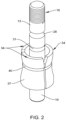
FIG. 2 is a perspective view of the assembly ofFIG. 1 with the collar assembly removed for clarity. -
FIG. 3 is a sectional elevation view of the quick release endpoint attachment assembly in the closed position. -
FIG. 4 is a sectional elevation view of the quick release endpoint attachment assembly in the open position. - At the outset, it should be clearly understood that like reference numerals are intended to identify the same structural elements, portions or surfaces consistently throughout the several drawing figures, as such elements, portions or surfaces may be further described or explained by the entire written specification, of which this detailed description is an integral part. Unless otherwise indicated, the drawings are intended to be read (e.g., cross-hatching, arrangement of parts, proportion, debris, etc.) together with the specification, and are to be considered a portion of the entire written description of this invention. As used in the following description, the terms "horizontal", "vertical", "left", "right", "up" and "down", as well as adjectival and adverbial derivatives thereof, (e.g., "horizontally", "rightwardly", "upwardly", etc.), simply refer to the orientation of the illustrated structure as the particular drawing figure faces the reader. Similarly, the terms "inwardly" and "outwardly" generally refer to the orientation of a surface relative to its axis of elongation, or of rotation, as appropriate.
- Referring now to the drawings, and more particularly to
FIG. 1 thereof, this invention provides a quick releaseendpoint attachment assembly 10. Theassembly 10 may include afirst shaft 13 extending upward. Thefirst shaft 13 may be connected to a material handling device such as a hoist or the like. Thefirst shaft 13 may be provided withexternal threads 16 for engaging with the material handling device. Asecond shaft 19 extends downward from the bottom of theassembly 10 and may be configured to support suspension/rigging components such as, but not limited to, hooks, wire grips, eyelets, dynamometers, or the like. - A
collar assembly 22 surrounds the junction of the first andsecond shafts collar assembly 22 may include a channel for receiving alocking pin 25. Thelocking pin 25 may be configured to secure theassembly 10 in the open or closed position as described in greater detail below. - Turning to
FIG. 2 , thefirst shaft 13 is shown in greater detail with thecollar assembly 22 removed for clarity. Thefirst shaft 13 may be provided with afirst groove 28 located below thethreads 16. Asecond groove 31 may be provided below thefirst groove 28. As shown thegrooves second groove 31, one or moreload carrying fingers 34 may be provided. Theload carrying fingers 34 surround thefirst shaft 13 and thesecond shaft 19 and connect theshafts outer surface 37 of theload carrying finger 34 may be provided with agroove 40 disposed in a midportion of theload carrying finger 34. - Turning to
FIGS. 3 and4 , the quick releaseendpoint attachment assembly 10 is shown in the closed position. Thecollar assembly 22 may be provided with atop member 41 that has acentral opening 43 that is configured to receive thefirst shaft 13. Thetop member 41 may also be formed with an extendedportion 46 having acylindrical channel 49 defined therein. As shown, the midportion of the extendedportion 46 may have a cutaway section that intersects with thecentral opening 43. When thefirst shaft 13 is inserted through thecentral opening 43, the first orsecond grooves cylindrical channel 49 as shown. In the closed position, thesecond groove 31 is disposed in registry with thecylindrical channel 49 such that thelocking pin 25 extends through both ends of theextended portion 46 and in the middle it extends through around opening 50 formed by thesecond groove 31 and a portion of thecylindrical channel 49. When thefirst shaft 13 is inserted as shown inFIG. 3 , thesecond groove 31 and thecylindrical channel 49 combine to form acircular opening 50. When thelocking pin 25 is inserted through the opening 50, it is held in position between the wall of theshaft 13 forming thesecond groove 31 and the inner wall of thecylindrical channel 49 defining opening 50. In this position, thelocking pin 25 prevents thecollar assembly 22 from movement relative to thefirst shaft 13. - The
locking pin 25 is positioned inside thecylindrical channel 49 formed in the top of thecollar assembly 10. In the position shown, thechannel 49 aligns with thesecond groove 31. - The
top member 41 of thecollar assembly 22 may be provided with a pair ofopposed members top member 41. Thetop member 41 may support a downward extending roundmember 61 that has anouter surface 64 and aninner surface 67. Theinner surface 67 has an internal profile 70 (FIG. 4 ) that is configured to engage with the one or moreload carrying fingers 34 when thecollar assembly 10 slides over the first andsecond shaft profile 70 extends downward along astraight section 73. From thestraight section 73, theprofile 70 has an inwardangled section 76. From aninnermost point 79, theprofile 70 has an outward angledsection 82. The outwardangled section 82 extends to anotherstraight section 85. Theinnermost point 79 of theprofile 70 engages with theouter surface 37 of theload carrying fingers 34. - The
load carrying fingers 34 surround the first andsecond shafts groove 40 on theouter surface 37 of theload carrying fingers 34 is configured to receive agarter spring 88. Thegarter spring 88 is configured to provide an inward radial force to hold theload carrying fingers 34 in position during installation. - The
load carrying fingers 34 have aninner surface 91 that engages with the first andsecond shafts inner surface 91 has afirst protrusion 94 and asecond protrusion 100. Thefirst protrusion 94 is configured to align with athird groove 97 on thefirst shaft 13. Thesecond protrusion 100 is configured to align with afirst groove 103 disposed on thesecond shaft 19. Thegroove 40 on the outside of theload carrying fingers 34 may be aligned with thefirst protrusion 94. During installation, when thespring 88 is engaged around theload carrying fingers 34, the force of thespring 88 causes thefirst protrusion 94 to bear against thethird groove 97 on thefirst shaft 13. - From the bottom of the
spring 88 to the bottom of theload carrying fingers 34, theouter surface 37 of theload carrying fingers 34 is biased outward away from engagement with thefirst groove 103 disposed on thesecond shaft 19. - The
profile 70 on the inner surface of thecollar assembly 22 extends inward such that it bears against theouter surface 37 of theload carrying finger 34. In the closed position shown inFIG. 3 , the bottom of theprofile 70 on thecollar assembly 22 engages with the bottom of theload carrying fingers 34 and causes thesecond protrusion 100 to bear against thefirst groove 103 disposed on thesecond shaft 19. When thecollar assembly 22 is disposed around theload carrying fingers 34, it provides a radial force holding theload carrying fingers 34 against theshafts - With the
collar assembly 22 in the position shown inFIG. 3 , theassembly 10 is in the closed position and thesecond shaft 19 is securely connected to theassembly 10. - Turning to
FIG. 4 , with thepin 25 removed from thechannel 49, theassembly 10 can be moved from the closed position ofFIG. 3 to the open position ofFIG. 4 . As shown thecollar assembly 22 has been slid upward such that theopening 50 in thecylindrical channel 49 aligns with thefirst groove 28 on thefirst shaft 13. In this position, the bottom of thecollar assembly 22 has been moved upward relative to the end of theload carrying fingers 34. Theload carrying fingers 34 remain in the same position under the radial force of thecollar assembly 22 which causes thefirst protrusion 94 to remain engaged with thethird groove 97 on thefirst shaft 13. With theinner profile 70 of thecollar assembly 70 removed from engagement with the bottom of theload carrying fingers 34, theload carrying fingers 34 spread out at the bottom and move away from thesecond shaft 19. Accordingly, thesecond protrusions 100 exit from thefirst groove 103 disposed on thesecond shaft 19. With thesecond shaft 19 no longer engaged by theload carrying fingers 34, thesecond shaft 19 is released from theassembly 10. As a result, thesecond shaft 19 can be quickly replaced by another suspension/rigging component without the use of tools. - The present invention contemplates that many changes and modifications may be made. Therefore, while the presently-preferred form of the quick release endpoint attachment assembly has been shown and described, and several modifications and alternatives discussed, persons skilled in this art will readily appreciate that various additional changes and modifications may be made without departing from the spirit of the invention, as defined and differentiated by the following claims.
Claims (17)
- A quick release end point attachment assembly, comprising:a first shaft having a first groove, a second groove, and a third groove defined therein;a collar assembly having a central opening configured to receive the first shaft,the collar assembly configured to slide relative to the first shaft in the direction of a longitudinal axis of the first shaft;a second shaft having a first groove defined therein, the second shaft configured to be arranged end-to-end relative to the first shaft;one or more load carrying fingers having a first end and a second end, the one or more load carrying fingers disposed between the first and/or second shafts and the collar assembly, the one or more load carrying fingers having an inner surface with two or more protrusions defined therein, the first protrusion configured to engage with the third groove on the first shaft, the second protrusion configured to engage with the first groove on the second shaft;wherein the collar assembly has an internal profile disposed on an inner surface of the collar assembly, the internal profile configured to engage with a mating profile on an outer surface of the one or more load carrying fingers;wherein when the collar assembly is moved in the direction of the longitudinal axis of the first shaft from the open to the closed position, the inner surface of the collar assembly engages with the outer surface of the one or more load carrying fingers to cause the first and second protrusions to engage with the grooves in the first and second shaft to prevent relative movement between the first and second shafts and when the collar assembly is moved in the direction of the longitudinal axis of the first shaft from the closed to the open position, the collar assembly moves relative to the one or more load carrying fingers such that second protrusion exits from the first groove on the second shaft releasing the second shaft from the quick release end point attachment assembly.
- The assembly set forth in claim 1, the one or more load carrying fingers having an outer surface with a groove defined therein for receiving a garter spring.
- The assembly set forth in claim 2, wherein the garter spring engages with the groove on the outer surface of the load carrying fingers to hold the first protrusion in the third groove on the first shaft during installation.
- The assembly set forth in claim 1, wherein the second protrusion on the one or more load carrying fingers is biased in the open position.
- The assembly set forth in claim 1, wherein the collar assembly has an opening defined therein for receiving a locking pin, the opening configured such that when the collar assembly is disposed in an open position the locking pin can be inserted through the opening in the collar assembly into the first groove of the first shaft to lock the collar assembly relative to the first shaft in the open position and the opening configured such that when the collar assembly is disposed in an closed position the locking pin can be inserted through the opening in the collar assembly into the second groove on the first shaft to lock the collar assembly relative to the first shaft in the closed position.
- The assembly set forth in claim 1, wherein the first and second shafts are disposed in an end-to-end configuration.
- The assembly set forth in claim 1, wherein the first shaft is cylindrical.
- The assembly set forth in claim 1, wherein the second shaft is cylindrical.
- The assembly set forth in claim 1, wherein the first shaft has a threaded section.
- The assembly set forth in claim 1, wherein the second end of the load carrying fingers is biased in an open position.
- The assembly set forth in claim 1, wherein the collar assembly has a top member with a shoulder formed therein for receiving a downward extending member.
- The assembly set forth in claim 11, wherein the downward extending member has an inner surface with a profile having at least one section extending inward toward the load carrying fingers when the collar assembly is installed on the shafts.
- A quick release end point attachment assembly, comprising:a first shaft having a first groove, a second groove, and a third groove defined therein;a collar assembly having a central opening configured to receive the first shaft,the collar assembly configured to slide relative to the first shaft in the direction of a longitudinal axis of the first shaft;a second shaft having a first groove defined therein, the second shaft configured to be arranged end-to-end relative to the first shaft;one or more load carrying fingers having a first end and a second end, the one or more load carrying fingers disposed between the first and/or second shafts and the collar assembly, the one or more load carrying fingers having an inner surface with two or more protrusions defined therein, the first protrusion configured to engage with the third groove on the first shaft, the second protrusion configured to engage with the first groove on the second shaft;wherein the collar assembly has an internal profile disposed on an inner surface of the collar assembly, the internal profile configured to engage with a mating profile on an outer surface of the one or more load carrying fingers;wherein when the collar assembly is moved in the direction of the longitudinal axis of the first shaft from the open to the closed position, the inner surface of the collar assembly engages with the outer surface of the one or more load carrying fingers to cause the first and second protrusions to engage with the grooves in the first and second shaft to prevent relative movement between the first and second shafts and when the collar assembly is moved in the direction of the longitudinal axis of the first shaft from the closed to the open position, the collar assembly moves relative to the one or more load carrying fingers such that second protrusion exits from the first groove on the second shaft releasing the second shaft from the quick release end point attachment assembly; and,wherein the collar assembly has an opening defined therein for receiving a locking pin, the opening configured such that when the collar assembly is disposed in an open position the locking pin can be inserted through the opening in the collar assembly into the first groove of the first shaft to lock the collar assembly relative to the first shaft in the open position and the opening configured such that when the collar assembly is disposed in an closed position the locking pin can be inserted through the opening in the collar assembly into the second groove on the first shaft to lock the collar assembly relative to the first shaft in the closed position.
- The assembly set forth in claim 13, the one or more load carrying fingers having an outer surface with a groove defined therein for receiving a garter spring.
- The assembly set forth in claim 14, wherein the garter spring engages with the groove on the outer surface of the load carrying fingers to hold the first protrusion in the third groove on the first shaft during installation.
- The assembly set forth in claim 13, wherein the second protrusion on the one or more load carrying fingers is biased in the open position.
- A quick release end point attachment assembly, comprising:a first shaft having at least one groove defined therein;a collar assembly having a central opening configured to receive the first shaft,the collar assembly configured to slide relative to the first shaft in the direction of a longitudinal axis of the first shaft;a second shaft having at least one groove defined therein, the second shaft configured to be arranged end-to-end relative to the first shaft;one or more load carrying fingers having a first end and a second end, the one or more load carrying fingers disposed between the first and/or second shafts and the collar assembly, the one or more load carrying fingers having an inner surface with two or more protrusions defined therein, the first protrusion configured to engage with the at least one groove on the first shaft, the second protrusion configured to engage with the at least one groove on the second shaft;wherein the collar assembly has an internal profile disposed on an inner surface of the collar assembly, the internal profile configured to engage with a mating profile on an outer surface of the one or more load carrying fingers;wherein when the collar assembly is moved in the direction of the longitudinal axis of the first shaft from the open to the closed position, the inner surface of the collar assembly engages with the outer surface of the one or more load carrying fingers to cause the first and second protrusions to engage with the grooves in the first and second shaft to prevent relative movement between the first and second shafts and when the collar assembly is moved in the direction of the longitudinal axis of the first shaft from the closed to the open position, the collar assembly moves relative to the one or more load carrying fingers such that second protrusion exits from the first groove on the second shaft releasing the second shaft from the quick release end point attachment assembly
Applications Claiming Priority (1)
| Application Number | Priority Date | Filing Date | Title |
|---|---|---|---|
| US18/381,675 US20250128916A1 (en) | 2023-10-19 | 2023-10-19 | Quick Release End Point Attachment |
Publications (1)
| Publication Number | Publication Date |
|---|---|
| EP4542061A1 true EP4542061A1 (en) | 2025-04-23 |
Family
ID=93154527
Family Applications (1)
| Application Number | Title | Priority Date | Filing Date |
|---|---|---|---|
| EP24207103.3A Pending EP4542061A1 (en) | 2023-10-19 | 2024-10-17 | Quick release end point attachment |
Country Status (4)
| Country | Link |
|---|---|
| US (1) | US20250128916A1 (en) |
| EP (1) | EP4542061A1 (en) |
| CA (1) | CA3247571A1 (en) |
| MX (1) | MX2024012854A (en) |
Citations (1)
| Publication number | Priority date | Publication date | Assignee | Title |
|---|---|---|---|---|
| WO2021074616A1 (en) * | 2019-10-17 | 2021-04-22 | Jcco 330 Limited | Improvements in and relating to couplings |
-
2023
- 2023-10-19 US US18/381,675 patent/US20250128916A1/en active Pending
-
2024
- 2024-10-03 CA CA3247571A patent/CA3247571A1/en active Pending
- 2024-10-17 MX MX2024012854A patent/MX2024012854A/en unknown
- 2024-10-17 EP EP24207103.3A patent/EP4542061A1/en active Pending
Patent Citations (1)
| Publication number | Priority date | Publication date | Assignee | Title |
|---|---|---|---|---|
| WO2021074616A1 (en) * | 2019-10-17 | 2021-04-22 | Jcco 330 Limited | Improvements in and relating to couplings |
Also Published As
| Publication number | Publication date |
|---|---|
| CA3247571A1 (en) | 2025-06-02 |
| MX2024012854A (en) | 2025-05-02 |
| US20250128916A1 (en) | 2025-04-24 |
Similar Documents
| Publication | Publication Date | Title |
|---|---|---|
| CN102364132B (en) | Captive panel fastener assembly | |
| US9903440B2 (en) | Shackle with captured pin assembly | |
| KR20200085227A (en) | Grommet removal assemblies and methods | |
| EP3356698B1 (en) | Shackle pin split nut assembly | |
| US20090245924A1 (en) | Small Handling Pole Locking Assembly | |
| US6561720B2 (en) | Axial securing device for two components by means of a locking ring | |
| WO1996002730A1 (en) | Quick connect coupling | |
| US5588188A (en) | Swaged cable swivel hook assembly and swivel hook therefor | |
| EP0380195A1 (en) | Safety connection into passages in a tubular body | |
| US5460418A (en) | Shackle bolt safety retainer | |
| EP4542061A1 (en) | Quick release end point attachment | |
| EP3939928B1 (en) | Safety latch for a hook | |
| KR20190116487A (en) | Fastening Device and Fastening Assembly | |
| US12269714B2 (en) | Connection device for coupling a load to a lifting lug by means of a support bolt | |
| DE20305677U1 (en) | Cable channel especially for use with robots, has enclosure member with position changing closure part relative to cable guide | |
| DE20305680U1 (en) | Cable guideway of hinged links, each angled in several directions and open at front, fitted behind each other in longitudinal direction of guideway | |
| CN215763692U (en) | Anti-loosening steel belt type hoop | |
| US7354217B2 (en) | Fastening device and method for attaching an object to a support structure | |
| DE102011054148B4 (en) | Load-receiving means, in particular load hooks | |
| US10294980B2 (en) | Control cable quick disconnect | |
| US12540655B2 (en) | Shackle | |
| KR20250088382A (en) | Carabiner | |
| EP3267053A1 (en) | Carabiners | |
| HK40065430B (en) | Safety latch for a hook | |
| KR20170003146U (en) | Unit for connecting rope |
Legal Events
| Date | Code | Title | Description |
|---|---|---|---|
| PUAI | Public reference made under article 153(3) epc to a published international application that has entered the european phase |
Free format text: ORIGINAL CODE: 0009012 |
|
| STAA | Information on the status of an ep patent application or granted ep patent |
Free format text: STATUS: THE APPLICATION HAS BEEN PUBLISHED |
|
| AK | Designated contracting states |
Kind code of ref document: A1 Designated state(s): AL AT BE BG CH CY CZ DE DK EE ES FI FR GB GR HR HU IE IS IT LI LT LU LV MC ME MK MT NL NO PL PT RO RS SE SI SK SM TR |
|
| STAA | Information on the status of an ep patent application or granted ep patent |
Free format text: STATUS: REQUEST FOR EXAMINATION WAS MADE |
|
| 17P | Request for examination filed |
Effective date: 20251020 |
|
| GRAP | Despatch of communication of intention to grant a patent |
Free format text: ORIGINAL CODE: EPIDOSNIGR1 |
|
| STAA | Information on the status of an ep patent application or granted ep patent |
Free format text: STATUS: GRANT OF PATENT IS INTENDED |
|
| INTG | Intention to grant announced |
Effective date: 20260305 |
|
| RIN1 | Information on inventor provided before grant (corrected) |
Inventor name: GODBEY, JARED BENJAMIN |