EP4542055A1 - Pressurization device - Google Patents
Pressurization device Download PDFInfo
- Publication number
- EP4542055A1 EP4542055A1 EP23823994.1A EP23823994A EP4542055A1 EP 4542055 A1 EP4542055 A1 EP 4542055A1 EP 23823994 A EP23823994 A EP 23823994A EP 4542055 A1 EP4542055 A1 EP 4542055A1
- Authority
- EP
- European Patent Office
- Prior art keywords
- pressure
- tubular body
- piston
- diameter portion
- applying device
- Prior art date
- Legal status (The legal status is an assumption and is not a legal conclusion. Google has not performed a legal analysis and makes no representation as to the accuracy of the status listed.)
- Pending
Links
Images


Classifications
-
- B—PERFORMING OPERATIONS; TRANSPORTING
- B22—CASTING; POWDER METALLURGY
- B22D—CASTING OF METALS; CASTING OF OTHER SUBSTANCES BY THE SAME PROCESSES OR DEVICES
- B22D17/00—Pressure die casting or injection die casting, i.e. casting in which the metal is forced into a mould under high pressure
- B22D17/20—Accessories: Details
- B22D17/32—Controlling equipment
-
- F—MECHANICAL ENGINEERING; LIGHTING; HEATING; WEAPONS; BLASTING
- F15—FLUID-PRESSURE ACTUATORS; HYDRAULICS OR PNEUMATICS IN GENERAL
- F15B—SYSTEMS ACTING BY MEANS OF FLUIDS IN GENERAL; FLUID-PRESSURE ACTUATORS, e.g. SERVOMOTORS; DETAILS OF FLUID-PRESSURE SYSTEMS, NOT OTHERWISE PROVIDED FOR
- F15B15/00—Fluid-actuated devices for displacing a member from one position to another; Gearing associated therewith
- F15B15/08—Characterised by the construction of the motor unit
-
- B—PERFORMING OPERATIONS; TRANSPORTING
- B22—CASTING; POWDER METALLURGY
- B22D—CASTING OF METALS; CASTING OF OTHER SUBSTANCES BY THE SAME PROCESSES OR DEVICES
- B22D17/00—Pressure die casting or injection die casting, i.e. casting in which the metal is forced into a mould under high pressure
- B22D17/20—Accessories: Details
- B22D17/2015—Means for forcing the molten metal into the die
- B22D17/2069—Exerting after-pressure on the moulding material
-
- F—MECHANICAL ENGINEERING; LIGHTING; HEATING; WEAPONS; BLASTING
- F15—FLUID-PRESSURE ACTUATORS; HYDRAULICS OR PNEUMATICS IN GENERAL
- F15B—SYSTEMS ACTING BY MEANS OF FLUIDS IN GENERAL; FLUID-PRESSURE ACTUATORS, e.g. SERVOMOTORS; DETAILS OF FLUID-PRESSURE SYSTEMS, NOT OTHERWISE PROVIDED FOR
- F15B1/00—Installations or systems with accumulators; Supply reservoir or sump assemblies
- F15B1/02—Installations or systems with accumulators
- F15B1/04—Accumulators
- F15B1/045—Dead weight accumulators
-
- F—MECHANICAL ENGINEERING; LIGHTING; HEATING; WEAPONS; BLASTING
- F15—FLUID-PRESSURE ACTUATORS; HYDRAULICS OR PNEUMATICS IN GENERAL
- F15B—SYSTEMS ACTING BY MEANS OF FLUIDS IN GENERAL; FLUID-PRESSURE ACTUATORS, e.g. SERVOMOTORS; DETAILS OF FLUID-PRESSURE SYSTEMS, NOT OTHERWISE PROVIDED FOR
- F15B15/00—Fluid-actuated devices for displacing a member from one position to another; Gearing associated therewith
- F15B15/20—Other details, e.g. assembly with regulating devices
- F15B15/204—Control means for piston speed or actuating force without external control, e.g. control valve inside the piston
-
- F—MECHANICAL ENGINEERING; LIGHTING; HEATING; WEAPONS; BLASTING
- F15—FLUID-PRESSURE ACTUATORS; HYDRAULICS OR PNEUMATICS IN GENERAL
- F15B—SYSTEMS ACTING BY MEANS OF FLUIDS IN GENERAL; FLUID-PRESSURE ACTUATORS, e.g. SERVOMOTORS; DETAILS OF FLUID-PRESSURE SYSTEMS, NOT OTHERWISE PROVIDED FOR
- F15B15/00—Fluid-actuated devices for displacing a member from one position to another; Gearing associated therewith
- F15B15/08—Characterised by the construction of the motor unit
- F15B15/14—Characterised by the construction of the motor unit of the straight-cylinder type
- F15B15/1423—Component parts; Constructional details
- F15B15/1457—Piston rods
- F15B15/1461—Piston rod sealings
-
- F—MECHANICAL ENGINEERING; LIGHTING; HEATING; WEAPONS; BLASTING
- F15—FLUID-PRESSURE ACTUATORS; HYDRAULICS OR PNEUMATICS IN GENERAL
- F15B—SYSTEMS ACTING BY MEANS OF FLUIDS IN GENERAL; FLUID-PRESSURE ACTUATORS, e.g. SERVOMOTORS; DETAILS OF FLUID-PRESSURE SYSTEMS, NOT OTHERWISE PROVIDED FOR
- F15B15/00—Fluid-actuated devices for displacing a member from one position to another; Gearing associated therewith
- F15B15/08—Characterised by the construction of the motor unit
- F15B15/14—Characterised by the construction of the motor unit of the straight-cylinder type
- F15B15/1423—Component parts; Constructional details
- F15B15/1471—Guiding means other than in the end cap
-
- F—MECHANICAL ENGINEERING; LIGHTING; HEATING; WEAPONS; BLASTING
- F15—FLUID-PRESSURE ACTUATORS; HYDRAULICS OR PNEUMATICS IN GENERAL
- F15B—SYSTEMS ACTING BY MEANS OF FLUIDS IN GENERAL; FLUID-PRESSURE ACTUATORS, e.g. SERVOMOTORS; DETAILS OF FLUID-PRESSURE SYSTEMS, NOT OTHERWISE PROVIDED FOR
- F15B15/00—Fluid-actuated devices for displacing a member from one position to another; Gearing associated therewith
- F15B15/20—Other details, e.g. assembly with regulating devices
- F15B15/24—Other details, e.g. assembly with regulating devices for restricting the stroke
-
- F—MECHANICAL ENGINEERING; LIGHTING; HEATING; WEAPONS; BLASTING
- F15—FLUID-PRESSURE ACTUATORS; HYDRAULICS OR PNEUMATICS IN GENERAL
- F15B—SYSTEMS ACTING BY MEANS OF FLUIDS IN GENERAL; FLUID-PRESSURE ACTUATORS, e.g. SERVOMOTORS; DETAILS OF FLUID-PRESSURE SYSTEMS, NOT OTHERWISE PROVIDED FOR
- F15B2201/00—Accumulators
- F15B2201/30—Accumulator separating means
- F15B2201/31—Accumulator separating means having rigid separating means, e.g. pistons
-
- F—MECHANICAL ENGINEERING; LIGHTING; HEATING; WEAPONS; BLASTING
- F15—FLUID-PRESSURE ACTUATORS; HYDRAULICS OR PNEUMATICS IN GENERAL
- F15B—SYSTEMS ACTING BY MEANS OF FLUIDS IN GENERAL; FLUID-PRESSURE ACTUATORS, e.g. SERVOMOTORS; DETAILS OF FLUID-PRESSURE SYSTEMS, NOT OTHERWISE PROVIDED FOR
- F15B2201/00—Accumulators
- F15B2201/30—Accumulator separating means
- F15B2201/31—Accumulator separating means having rigid separating means, e.g. pistons
- F15B2201/312—Sealings therefor, e.g. piston rings
-
- F—MECHANICAL ENGINEERING; LIGHTING; HEATING; WEAPONS; BLASTING
- F15—FLUID-PRESSURE ACTUATORS; HYDRAULICS OR PNEUMATICS IN GENERAL
- F15B—SYSTEMS ACTING BY MEANS OF FLUIDS IN GENERAL; FLUID-PRESSURE ACTUATORS, e.g. SERVOMOTORS; DETAILS OF FLUID-PRESSURE SYSTEMS, NOT OTHERWISE PROVIDED FOR
- F15B2215/00—Fluid-actuated devices for displacing a member from one position to another
- F15B2215/30—Constructional details thereof
Definitions
- the present invention relates to a pressure applying device, for example, a pressure applying device that applies pressure to a working object.
- a cylinder device used as a pressure applying device that applies pressure to a working object using the pressure of a fluid
- a piston can apply pressure to the working object by receiving the pressure of the fluid and moving inside a cylinder.
- a pressure applying device of Patent Citation 1 includes a cylinder device, a pump, and an accumulator.
- a pressurized fluid is supplied to the cylinder device from the pump or the accumulator, a piston moves relative to a cylinder inside the cylinder to apply pressure to a working object.
- Patent Citation 1 JP 2021-20224 A (Page 5, FIG. 1 )
- the present invention has been made in view of such problems, and an object of the present invention is to provide a pressure applying device capable of applying pressure to a working object with a substantially constant force through a compact structure.
- a pressure applying device includes a pressure accumulating portion; a piston including a small-diameter portion inserted into a cylinder portion on a pressure accumulating portion side, and a large-diameter portion disposed close toa working object; and a tubular body extending from the large-diameter portion to the cylinder portion, wherein a lubricating fluid is held inside the tubular body.
- the pressure of the pressure accumulating portion acting on the small-diameter portion is dispersed in the large-diameter portion and is transmitted to an object to be acted upon, a change in the pressure applied to the object to be acted upon within the stroke range of the piston can be reduced with a compact structure in which an accumulator, a pump, or the like is not used. Further, the stroke of the piston can be smoothly performed due to the lubricating fluid held inside the tubular body.
- the cylinder portion and the tubular body are slidable on each other. According to this preferable configuration, since the movement of the piston is guided by the small-diameter portion inside the cylinder portion and the tubular body outside the cylinder portion, the stroke of the piston is stabilized.
- a breathing hole is formed at an upper portion of the tubular body. According to this preferable configuration, since an increase or a decrease in the pressure in the tubular body due to the breathing hole when the piston moves can be suppressed, the piston moves smoothly.
- the breathing hole is provided at a position where the breathing hole is not closed when the tubular body is inserted the furthest into the cylinder portion. According to this preferable configuration, the piston moves smoothly throughout the entire stroke of the piston.
- the pressure applying device further includes a movement restricting portion that restricts a movement of the tubular body in an insertion direction.
- the movement of the tubular body in the insertion direction is restricted by the movement restricting portion, so that the breathing hole is reliably prevented from being closed.
- the lubricating fluid is held such that a liquid level is at least at a height position of the small-diameter portion when the tubular body is inserted the furthest into the cylinder portion. According to this preferable configuration, since the lubricating fluid is supplied to a gap between the cylinder portion and the small-diameter portion, the piston moves smoothly.
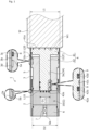
- a pressure applying device according to a first embodiment of the present invention will be described with reference to FIGS. 1 and 2 .
- the description will be made based on the assumption that the left side of the drawing sheet of FIG. 1 is a left side of the pressure applying device and the right side of the drawing sheet of FIG. 1 is a right side of the pressure applying device.
- a pressure applying device 1 applies pressure to a working object W using the pressure of a fluid.
- the description will be made based on the assumption that the working object W of the present embodiment is disposed on the right side of the pressure applying device 1 and the position of a pressure applied surface W1 changes in an axial direction, namely, a left-right direction of the drawing sheet of FIG. 1 depending on the state of use.
- the pressure applying device 1 mainly includes a casing 2, a connecting body 3 as a cylinder portion, a piston 4 as a pressure transmitting body, and a tubular body 5 as a guide body.
- the casing 2 has a tubular shape.
- a right end portion of an outer peripheral surface of the casing 2 has a smaller diameter than a left end portion.
- a step portion 2a serving as a movement restricting portion is formed in an annular shape on the outer peripheral surface of the casing 2.
- a lid member 6 is connected to an inner peripheral surface of the left end portion of the casing 2 in a sealed manner by screwing.
- a through-hole 6a is formed at a central portion of the lid member 6.
- a plug 7 is attached to the through-hole 6a.
- the casing 2 and the lid member 6 may be integrally formed from the same member.
- the connecting body 3 has a stepped tubular shape having a through-hole 3A.
- a left end portion of the connecting body 3 is screwed and connected to an inner peripheral surface of the right end portion of the casing 2 in a sealed manner.
- a mode in which the casing 2 and the connecting body 3 are separate bodies has been provided as an example; however, the casing 2 and the connecting body 3 may be integrally formed from the same member.
- Annular recessed portions 3c and 3d recessed in a radially inward direction are provided spaced apart from each other in the axial direction on an outer peripheral surface 3b of a flange of a right end portion of the connecting body 3, the flange extending in a radially outward direction.
- a seal ring 8 is fitted and disposed in the annular recessed portion 3c on the right side.
- the annular recessed portion 3d on the left side is shallower than the annular recessed portion 3c, and the seal ring 8 is not fitted into the annular recessed portion 3d.
- the piston 4 includes a large-diameter portion 41 and a small-diameter portion 42.
- the large-diameter portion 41 has a disk shape.
- the small-diameter portion 42 has a columnar shape, and extends from a central portion of the large-diameter portion 41 toward the left side.
- a diameter L1 of the large-diameter portion 41 is larger than a diameter L2 of the small-diameter portion 42, and in the present embodiment, is a dimension of approximately three times the diameter L2.
- the diameter L1 of the large-diameter portion 41 may be larger than the diameter L2 of the small-diameter portion 42, and preferably, the diameter L1 of the large-diameter portion 41 may be a dimension of approximately 2 to 5 times the diameter L2 of the small-diameter portion 42.
- the large-diameter portion 41 has a flat end surface 41a on the right side.
- the end surface 41a is disposed to be able to come into direct contact with and separate from the working object W. Specifically, the end surface 41a comes into surface contact with the pressure applied surface W1 of the working object W. Incidentally, the end surface 41a may be stuck to the pressure applied surface W1 of the working object W, and move integrally with the working object W.
- the small-diameter portion 42 is inserted and disposed in the through-hole 3A of the connecting body 3 to be slidable on an inner peripheral surface 3a of the connecting body 3.
- Four annular recessed portions 42a to 42d recessed in the radially inward direction are provided spaced apart from each other in the axial direction on the left side of an outer peripheral surface of the small-diameter portion 42.
- the leftmost annular recessed portion 42a and the third annular recessed portion 42c from the left side are formed to be shallower than the second annular recessed portion 42b from the left side and the rightmost annular recessed portion 42d.
- a seal ring 9 is fitted and disposed in each of the annular recessed portion 42b and the annular recessed portion 42d. Incidentally, the seal rings 9 are not fitted into the annular recessed portions 42a and 42c.
- seal ring 9 An X-ring has been described as an example of the seal ring 9; however, the seal ring 9 may be of any type such as an O-ring and a lip seal. Further, since a plurality of the seal rings 9, specifically, two seal rings 9 are disposed in the axial direction, there is almost no oil leakage to a pressure accumulating portion 10, and the piston 4 is less likely to tilt during movement.
- annular recessed portions 42a and 42c have a gas reservoir function and an oil reservoir function, and can prevent gas leakage and allow smooth sliding.
- the seal rings 9 are slidable in the axial direction with respect to the inner peripheral surface 3a of the connecting body 3, and restrict movement of the fluid in the axial direction.
- the pressure accumulating portion 10 is formed on the left side of the pressure applying device 1. Specifically, the pressure accumulating portion 10 is a space surrounded by the casing 2, the connecting body 3, the piston 4, and the lid member 6. The capacity of the pressure accumulating portion 10 changes as the piston 4 moves as will be described later (refer to FIG. 2 ).
- High-pressure gas G from the outside through a gas introduction port (not illustrated) of the plug 7 is sealed in the pressure accumulating portion 10.
- the pressure accumulating portion 10 is a cylinder-shaped gas chamber.
- a diameter D1 of the through-hole 3A of the connecting body 3 is smaller than a diameter D2 of the pressure accumulating portion 10, and in the present embodiment, is a dimension of approximately 1/3 times the diameter D2 (D1 ⁇ D2).
- the diameter D1 of the through-hole 3A may be smaller than the diameter D2 of the pressure accumulating portion 10, and preferably, the diameter D1 of the through-hole 3A is a dimension of approximately 1/2 to 1/5 times the diameter D2 of the pressure accumulating portion 10.
- a right end portion of the tubular body 5 is screwed and connected to an outer peripheral surface of the large-diameter portion 41 in a sealed manner, and the tubular body 5 is integrated with the piston 4.
- a right end surface of the tubular body 5 is disposed to be substantially flush with the end surface 41a on the right side of the large-diameter portion 41 or on the left side with respect to the end surface 41a. According to this configuration, the tubular body 5 does not hinder surface contact between the end surface 41a of the large-diameter portion 41 and the pressure applied surface W1 of the working object W.
- tubular body 5 is externally inserted to the connecting body 3, and an inner peripheral surface 5a of the tubular body 5 is slidable in the axial direction with respect to the outer peripheral surface 3b of the right end portion of the connecting body 3.
- the seal ring 8 restricts movement of the fluid in the axial direction between the inner peripheral surface 5a of the tubular body 5 and the outer peripheral surface 3b of the connecting body 3.
- a space portion 11 is formed on the right side of the pressure applying device 1 by the connecting body 3, the large-diameter portion 41 of the piston 4, and the tubular body 5. Oil F as a lubricating fluid is held in the space portion 11. The capacity of the space portion 11 changes as the piston 4 moves as will be described later (refer to FIG. 2 ).
- a breathing hole 51 is formed at an upper right portion of the tubular body 5. Namely, the space portion 11 communicates with the external atmospheric space through the breathing hole 51.
- an end portion 5b on the left side of the tubular body 5 projects toward a radially inner side.
- the piston 4 and the tubular body 5 have moved to a leftmost position, in other words, when the tubular body 5 is inserted the furthest into the connecting body 3, the end portion 5b comes into contact with the step portion 2a of the casing 2.
- the casing 2 is fixed to a fixed body (not illustrated), and is immovable at least in the axial direction, namely, the left-right direction.
- the pressure applying device 1 in a state where the working object W is disposed at the leftmost position, the pressure applying device 1 is in the contracted state where the piston 4 and the tubular body 5 have moved to the leftmost position.
- the pressure applying device 1 is in the contracted state, the end portion 5b on the left side of the tubular body 5 comes into contact with the step portion 2a of the casing 2, and the movement of the piston 4 and the tubular body 5 toward the left side is restricted.
- the pressure applying device 1 When the pressure applying device 1 is in the contracted state, the capacity of the pressure accumulating portion 10 is at its smallest within the stroke range of the piston 4, and the gas G is in the most compressed state. The movement of the gas G toward the space portion 11 on the right side is restricted by the seal rings 9 and 9.
- the annular recessed portions 42a and 42c function as gas reservoirs, so that the leakage of the gas G can be suppressed.
- the pressure of the gas G in the pressure accumulating portion 10 acts on a left surface 42e of the small-diameter portion 42 (refer to arrow L10).
- the pressure of the gas G acting on the left surface 42e of the small-diameter portion 42 is transmitted to the working object W, as stress dispersed in the large-diameter portion 41 (refer to arrow L20).
- the breathing hole 51 of the tubular body 5 is disposed on the right side with respect to the connecting body 3. Namely, the breathing hole 51 is not closed.
- a water-repellent ventilation sheet 51s is installed to close the breathing hole 51, and allows gas to flow while preventing water from entering the space portion 11 from the outside.
- the liquid level of the oil F is located in the vicinity of a bottom of the breathing hole 51. Accordingly, the oil F is supplied to a gap between the outer peripheral surface of the small-diameter portion 42 of the piston 4 and the inner peripheral surface 3a of the connecting body 3, and the oil F does not leak from the breathing hole 51 to the atmospheric space.
- the pressure applying device 1 in a state where the pressure applied surface W1 of the working object W is disposed at a rightmost position, the pressure applying device 1 is in the extended state where the piston 4 and the tubular body 5 have moved to the rightmost position.
- the end portion 5b on the left side of the tubular body 5 comes into contact with a step portion 3e of the connecting body 3, and the movement of the piston 4 and the tubular body 5 toward the right side is restricted.
- the breathing hole 51 moves in a direction separated from the connecting body 3, namely, toward the right side compared to when the pressure applying device 1 is in the contracted state, so that the breathing hole 51 is not closed.
- the liquid level of the oil F is located below the through-hole 3A of the connecting body 3.
- the required capacity of the pressure accumulating portion 10 can be made smaller than, for example, when the piston has the same single diameter and the gas G is at a low pressure (the same pressure as in the space portion 11 or the like).
- the stroke of the piston 4 becomes smooth due to the oil F supplied to the gap between the outer peripheral surface of the small-diameter portion 42 of the piston 4 and the inner peripheral surface 3a of the connecting body 3. Incidentally, some of the oil F remaining in the gap between the outer peripheral surface of the small-diameter portion 42 and the inner peripheral surface 3a of the connecting body 3 flows into the annular recessed portions 42a and 42c, and contributes to lubricity of the stroke of the piston 4.
- the oil F in the space portion 11 enters a gap between the outer peripheral surface 3b of the connecting body 3 and the inner peripheral surface 5a of the tubular body 5 when the tubular body 5 moves toward the left side as will be described later, and the movement of the tubular body 5 becomes smooth due to the oil F remaining in the gap.
- the stroke of the piston 4 can be smoothly performed due to the oil F remaining in the gap between the outer peripheral surface of the small-diameter portion 42 and the inner peripheral surface 3a of the connecting body 3.
- the oil F in the space portion 11 enters the gap between the outer peripheral surface 3b of the connecting body 3 and the inner peripheral surface 5a of the tubular body 5, and the movement of the tubular body 5 also becomes smooth. Some of the oil F remaining in the gap between the outer peripheral surface 3b of the connecting body 3 and the inner peripheral surface 5a of the tubular body 5 flows into the annular recessed portion 3d , and contributes to the lubricity of the stroke of the tubular body 5.
- the breathing hole 51 is not closed throughout the entire stroke of the piston 4, the pressure in the space portion 11 can be prevented from increasing, and the piston 4 can be stably stroked.
- the pressure of the pressure accumulating portion 10 acting on the small-diameter portion 42 is dispersed in the large-diameter portion 41 and is transmitted to the working object W, a change in the pressure applied to the working object W within the stroke range of the piston 4 can be reduced with a compact structure in which an accumulator, a pump, or the like is not used. Further, the oil F is held in the space portion 11 inside the tubular body 5, and the stroke of the piston 4 can be smoothly performed due to the oil F.
- the tubular body 5 is slidable with respect to the outer peripheral surface 3b of the connecting body 3. According to this configuration, since the piston 4 is guided in the movement direction by the small-diameter portion 42 inside the connecting body 3 and the tubular body 5 outside the connecting body 3, the stroke of the piston 4 is stabilized.
- the breathing hole 51 is formed at an upper portion of the tubular body 5. According to this configuration, since an increase or a decrease in the pressure in the space portion 11 due to the breathing hole 51 when the piston 4 moves can be suppressed, the piston 4 moves smoothly.
- the breathing hole 51 is provided at a position where the breathing hole 51 is not closed when the tubular body 5 is inserted the furthest into the connecting body 3. According to this configuration, since the breathing hole 51 is not closed throughout the entire stroke of the piston 4, the pressure in the space portion 11 can be prevented from increasing due to the stroke of the piston 4.
- the tubular body 5 when the tubular body 5 is inserted the furthest into the connecting body 3, the tubular body 5 comes into contact with the step portion 2a of the casing 2, and the movement of the tubular body 5 in an insertion direction is restricted, so that the breathing hole 51 is reliably prevented from being closed.
- the oil F is held such that the liquid level of the oil F is at least at the height position of the small-diameter portion 42 when the tubular body 5 is inserted the furthest into the connecting body 3. According to this configuration, since the oil F is supplied to the gap between the connecting body 3 and the small-diameter portion 42, the piston 4 moves smoothly.
- the pressure applying device 1 is short in total length and is compact.
- a pressure applying device according to a second embodiment of the present invention will be described with reference to FIGS. 3 and 4 . Incidentally, the description of configurations that are the same as and overlap with the configurations of the first embodiment will be omitted.
- a left end portion of a tubular body 50 is connected to a right end portion of a connecting body 30 in a sealed manner by screwing.
- the connecting body 30 and the tubular body 50 may be integrally formed from the same member.
- a breathing hole 510 of the tubular body 50 is provided at an upper left portion of the tubular body 50, and is closed by a water-repellent ventilation sheet 510s.
- a lid body 520 having an annular shape is attached to a right end portion of the tubular body 50.
- a piston 40 includes a large-diameter portion 410, a small-diameter portion 420, and a medium-diameter portion 430.
- the medium-diameter portion 430 has a columnar shape, and extends from a central portion of the large-diameter portion 410 toward the right side.
- the medium-diameter portion 430 has a smaller diameter than the large-diameter portion 410, and has a larger diameter than the small-diameter portion 420.
- the medium-diameter portion 430 is inserted into a through-hole 520A of the lid body 520.
- a right end portion of the medium-diameter portion 430 is disposed at a right position with respect to the lid body 520, and a locking member 12 having a U shape in a cross-sectional view and serving as a movement restricting portion is fitted and fixed to the right end portion.
- a flat right surface 12a of the locking member 12 is in surface contact with the pressure applied surface W1 of the working object W.
- the breathing hole 510 of the tubular body 50 is disposed on the left side with respect to the large-diameter portion 410 of the piston 40.
- the oil F can be supplied to a gap between the small-diameter portion 420 and the connecting body 30.
- the breathing hole 510 is not closed throughout the entire stroke of the piston 40, the pressure in a space portion 110 can be prevented from increasing due to the stroke of the piston 40.
- the oil F enters a gap between an inner peripheral surface of the tubular body 50 and an outer peripheral surface of the large-diameter portion 410, so that the stroke of the piston 40 can be smoothly performed.
- a mode in which the gas is pressurized and accumulated in the pressure accumulating portion has been provided as an example; however, a liquid such as oil or a mixture of a liquid and a gas may be sealed in the pressure accumulating portion.
- a mode in which the stroke of the piston is guided by the tubular body and the small-diameter portion has been provided as an example; however, the present invention is not limited thereto, and a separate guide body other than the tubular body and the small-diameter portion may be provided.
- the stroke of the piston may be guided by providing a guide hole in the cylinder portion, providing a guide pin in the piston, and sliding the guide hole and the guide pin in a stroke direction.
- the tubular body is guided by an outer periphery of the casing of the pressure accumulating portion has been described; however, the tubular body may be guided by an outer periphery of the connecting body.
- the large-diameter portion of the piston is in direct contact with the working object; however, a separate member may be interposed between the large-diameter portion of the piston and the working object.
- a mode in which the breathing holes 51 and 510 are provided in the tubular bodies 5 and 50, respectively, has been provided as an example; however, the breathing holes 51 and 510 may not be provided, and in addition to a change in the pressure of the pressure accumulating portion 10, a change in the pressure of the space portion 11 may also be used.
- annular recessed portion 3d and the annular recessed portions 42a and 42c are fluid reservoir spaces
- a component having a bearing function, a component that enhances lubricity, and a component that suppresses eccentricity may be inserted into the spaces.
Landscapes
- Engineering & Computer Science (AREA)
- Mechanical Engineering (AREA)
- Physics & Mathematics (AREA)
- Fluid Mechanics (AREA)
- General Engineering & Computer Science (AREA)
- Actuator (AREA)
Abstract
Description
- The present invention relates to a pressure applying device, for example, a pressure applying device that applies pressure to a working object.
- There is a cylinder device used as a pressure applying device that applies pressure to a working object using the pressure of a fluid, and a piston can apply pressure to the working object by receiving the pressure of the fluid and moving inside a cylinder.
- For example, a pressure applying device of Patent Citation 1 includes a cylinder device, a pump, and an accumulator. When a pressurized fluid is supplied to the cylinder device from the pump or the accumulator, a piston moves relative to a cylinder inside the cylinder to apply pressure to a working object.
- Patent Citation 1:
JP 2021-20224 A Page 5,FIG. 1 ) - However, in the pressure applying device of Patent Citation 1, in order to apply a substantially constant applied pressure to the working object, it is necessary to supply an appropriate fluid to the cylinder at any time using the pump and the accumulator, and the size of the pressure applying device is increased, which is a problem.
- The present invention has been made in view of such problems, and an object of the present invention is to provide a pressure applying device capable of applying pressure to a working object with a substantially constant force through a compact structure.
- In order to solve the foregoing problems, a pressure applying device according to the present invention includes a pressure accumulating portion; a piston including a small-diameter portion inserted into a cylinder portion on a pressure accumulating portion side, and a large-diameter portion disposed close toa working object; and a tubular body extending from the large-diameter portion to the cylinder portion, wherein a lubricating fluid is held inside the tubular body. According to the aforesaid feature of the present invention, since the pressure of the pressure accumulating portion acting on the small-diameter portion is dispersed in the large-diameter portion and is transmitted to an object to be acted upon, a change in the pressure applied to the object to be acted upon within the stroke range of the piston can be reduced with a compact structure in which an accumulator, a pump, or the like is not used. Further, the stroke of the piston can be smoothly performed due to the lubricating fluid held inside the tubular body.
- It may be preferable that the cylinder portion and the tubular body are slidable on each other. According to this preferable configuration, since the movement of the piston is guided by the small-diameter portion inside the cylinder portion and the tubular body outside the cylinder portion, the stroke of the piston is stabilized.
- It may be preferable that a breathing hole is formed at an upper portion of the tubular body. According to this preferable configuration, since an increase or a decrease in the pressure in the tubular body due to the breathing hole when the piston moves can be suppressed, the piston moves smoothly.
- It may be preferable that the breathing hole is provided at a position where the breathing hole is not closed when the tubular body is inserted the furthest into the cylinder portion. According to this preferable configuration, the piston moves smoothly throughout the entire stroke of the piston.
- It may be preferable that the pressure applying device further includes a movement restricting portion that restricts a movement of the tubular body in an insertion direction. According to this preferable configuration, the movement of the tubular body in the insertion direction is restricted by the movement restricting portion, so that the breathing hole is reliably prevented from being closed.
- It may be preferable that the lubricating fluid is held such that a liquid level is at least at a height position of the small-diameter portion when the tubular body is inserted the furthest into the cylinder portion. According to this preferable configuration, since the lubricating fluid is supplied to a gap between the cylinder portion and the small-diameter portion, the piston moves smoothly.
-
-
FIG. 1 is a longitudinal sectional view illustrating a contracted state of a pressure applying device according to a first embodiment of the present invention. -
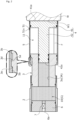
FIG. 2 is a longitudinal sectional view illustrating an extended state of the pressure applying device in the first embodiment. -
FIG. 3 is a longitudinal sectional view illustrating a contracted state of a pressure applying device according to a second embodiment of the present invention. -
FIG. 4 is a longitudinal sectional view illustrating an extended state of the pressure applying device in the second embodiment. - Modes for implementing a pressure applying device according to the present invention will be described below based on embodiments.
- A pressure applying device according to a first embodiment of the present invention will be described with reference to
FIGS. 1 and2 . Hereinafter, the description will be made based on the assumption that the left side of the drawing sheet ofFIG. 1 is a left side of the pressure applying device and the right side of the drawing sheet ofFIG. 1 is a right side of the pressure applying device. - As illustrated in
FIG. 1 , apressure applying device 1 applies pressure to a working object W using the pressure of a fluid. The description will be made based on the assumption that the working object W of the present embodiment is disposed on the right side of thepressure applying device 1 and the position of a pressure applied surface W1 changes in an axial direction, namely, a left-right direction of the drawing sheet ofFIG. 1 depending on the state of use. - The
pressure applying device 1 mainly includes acasing 2, a connectingbody 3 as a cylinder portion, apiston 4 as a pressure transmitting body, and atubular body 5 as a guide body. - The
casing 2 has a tubular shape. A right end portion of an outer peripheral surface of thecasing 2 has a smaller diameter than a left end portion. Namely, astep portion 2a serving as a movement restricting portion is formed in an annular shape on the outer peripheral surface of thecasing 2. - In addition, a
lid member 6 is connected to an inner peripheral surface of the left end portion of thecasing 2 in a sealed manner by screwing. A through-hole 6a is formed at a central portion of thelid member 6. Aplug 7 is attached to the through-hole 6a. Incidentally, thecasing 2 and thelid member 6 may be integrally formed from the same member. - The connecting
body 3 has a stepped tubular shape having a through-hole 3A. A left end portion of the connectingbody 3 is screwed and connected to an inner peripheral surface of the right end portion of thecasing 2 in a sealed manner. Incidentally, in the present embodiment, a mode in which thecasing 2 and the connectingbody 3 are separate bodies has been provided as an example; however, thecasing 2 and theconnecting body 3 may be integrally formed from the same member. - Annular recessed
portions peripheral surface 3b of a flange of a right end portion of the connectingbody 3, the flange extending in a radially outward direction. Aseal ring 8 is fitted and disposed in the annular recessedportion 3c on the right side. The annular recessedportion 3d on the left side is shallower than the annular recessedportion 3c, and theseal ring 8 is not fitted into the annular recessedportion 3d. - An O-ring has been described as an example of the
seal ring 8; however, theseal ring 8 may be of any type such as an X-ring and a lip seal. In addition, the annular recessedportion 3d has an oil reservoir function, and allows smooth sliding. Incidentally, the annular recessedportion 3d may be provided at any axial position on the outerperipheral surface 3b of the flange as long as the annular recessedportion 3d can enhance slidability. - The
piston 4 includes a large-diameter portion 41 and a small-diameter portion 42. The large-diameter portion 41 has a disk shape. The small-diameter portion 42 has a columnar shape, and extends from a central portion of the large-diameter portion 41 toward the left side. - A diameter L1 of the large-
diameter portion 41 is larger than a diameter L2 of the small-diameter portion 42, and in the present embodiment, is a dimension of approximately three times the diameter L2. Incidentally, the diameter L1 of the large-diameter portion 41 may be larger than the diameter L2 of the small-diameter portion 42, and preferably, the diameter L1 of the large-diameter portion 41 may be a dimension of approximately 2 to 5 times the diameter L2 of the small-diameter portion 42. - The large-
diameter portion 41 has aflat end surface 41a on the right side. Theend surface 41a is disposed to be able to come into direct contact with and separate from the working object W. Specifically, theend surface 41a comes into surface contact with the pressure applied surface W1 of the working object W. Incidentally, theend surface 41a may be stuck to the pressure applied surface W1 of the working object W, and move integrally with the working object W. - The small-
diameter portion 42 is inserted and disposed in the through-hole 3A of the connectingbody 3 to be slidable on an innerperipheral surface 3a of the connectingbody 3. Four annular recessedportions 42a to 42d recessed in the radially inward direction are provided spaced apart from each other in the axial direction on the left side of an outer peripheral surface of the small-diameter portion 42. - The leftmost annular
recessed portion 42a and the third annularrecessed portion 42c from the left side are formed to be shallower than the second annularrecessed portion 42b from the left side and the rightmost annularrecessed portion 42d. In addition, aseal ring 9 is fitted and disposed in each of the annular recessedportion 42b and the annular recessedportion 42d. Incidentally, the seal rings 9 are not fitted into the annular recessedportions - An X-ring has been described as an example of the
seal ring 9; however, theseal ring 9 may be of any type such as an O-ring and a lip seal. Further, since a plurality of the seal rings 9, specifically, twoseal rings 9 are disposed in the axial direction, there is almost no oil leakage to apressure accumulating portion 10, and thepiston 4 is less likely to tilt during movement. - In addition, the annular recessed
portions - The seal rings 9 are slidable in the axial direction with respect to the inner
peripheral surface 3a of the connectingbody 3, and restrict movement of the fluid in the axial direction. - By inserting the small-
diameter portion 42 into the through-hole 3A of the connectingbody 3, thepressure accumulating portion 10 is formed on the left side of thepressure applying device 1. Specifically, thepressure accumulating portion 10 is a space surrounded by thecasing 2, the connectingbody 3, thepiston 4, and thelid member 6. The capacity of thepressure accumulating portion 10 changes as thepiston 4 moves as will be described later (refer toFIG. 2 ). - High-pressure gas G from the outside through a gas introduction port (not illustrated) of the
plug 7 is sealed in thepressure accumulating portion 10. In other words, thepressure accumulating portion 10 is a cylinder-shaped gas chamber. - A diameter D1 of the through-
hole 3A of the connectingbody 3 is smaller than a diameter D2 of thepressure accumulating portion 10, and in the present embodiment, is a dimension of approximately 1/3 times the diameter D2 (D1 < D2). Incidentally, the diameter D1 of the through-hole 3A may be smaller than the diameter D2 of thepressure accumulating portion 10, and preferably, the diameter D1 of the through-hole 3A is a dimension of approximately 1/2 to 1/5 times the diameter D2 of thepressure accumulating portion 10. - A right end portion of the
tubular body 5 is screwed and connected to an outer peripheral surface of the large-diameter portion 41 in a sealed manner, and thetubular body 5 is integrated with thepiston 4. A right end surface of thetubular body 5 is disposed to be substantially flush with theend surface 41a on the right side of the large-diameter portion 41 or on the left side with respect to theend surface 41a. According to this configuration, thetubular body 5 does not hinder surface contact between theend surface 41a of the large-diameter portion 41 and the pressure applied surface W1 of the working object W. - In addition, the
tubular body 5 is externally inserted to the connectingbody 3, and an innerperipheral surface 5a of thetubular body 5 is slidable in the axial direction with respect to the outerperipheral surface 3b of the right end portion of the connectingbody 3. Theseal ring 8 restricts movement of the fluid in the axial direction between the innerperipheral surface 5a of thetubular body 5 and the outerperipheral surface 3b of the connectingbody 3. - A
space portion 11 is formed on the right side of thepressure applying device 1 by the connectingbody 3, the large-diameter portion 41 of thepiston 4, and thetubular body 5. Oil F as a lubricating fluid is held in thespace portion 11. The capacity of thespace portion 11 changes as thepiston 4 moves as will be described later (refer toFIG. 2 ). - A
breathing hole 51 is formed at an upper right portion of thetubular body 5. Namely, thespace portion 11 communicates with the external atmospheric space through thebreathing hole 51. - In addition, an
end portion 5b on the left side of thetubular body 5 projects toward a radially inner side. As will be described later, when thepiston 4 and thetubular body 5 have moved to a leftmost position, in other words, when thetubular body 5 is inserted the furthest into the connectingbody 3, theend portion 5b comes into contact with thestep portion 2a of thecasing 2. - Next, the contracted state and the extended state of the
pressure applying device 1 will be described usingFIGS. 1 and2 . Incidentally, thecasing 2 is fixed to a fixed body (not illustrated), and is immovable at least in the axial direction, namely, the left-right direction. - As illustrated in
FIG. 1 , in a state where the working object W is disposed at the leftmost position, thepressure applying device 1 is in the contracted state where thepiston 4 and thetubular body 5 have moved to the leftmost position. When thepressure applying device 1 is in the contracted state, theend portion 5b on the left side of thetubular body 5 comes into contact with thestep portion 2a of thecasing 2, and the movement of thepiston 4 and thetubular body 5 toward the left side is restricted. - When the
pressure applying device 1 is in the contracted state, the capacity of thepressure accumulating portion 10 is at its smallest within the stroke range of thepiston 4, and the gas G is in the most compressed state. The movement of the gas G toward thespace portion 11 on the right side is restricted by the seal rings 9 and 9. In addition, the annular recessedportions - The pressure of the gas G in the
pressure accumulating portion 10 acts on aleft surface 42e of the small-diameter portion 42 (refer to arrow L10). The pressure of the gas G acting on theleft surface 42e of the small-diameter portion 42 is transmitted to the working object W, as stress dispersed in the large-diameter portion 41 (refer to arrow L20). - In addition, when the
pressure applying device 1 is in the contracted state, thebreathing hole 51 of thetubular body 5 is disposed on the right side with respect to the connectingbody 3. Namely, thebreathing hole 51 is not closed. - Further, a water-
repellent ventilation sheet 51s is installed to close thebreathing hole 51, and allows gas to flow while preventing water from entering thespace portion 11 from the outside. - In addition, the liquid level of the oil F is located in the vicinity of a bottom of the
breathing hole 51. Accordingly, the oil F is supplied to a gap between the outer peripheral surface of the small-diameter portion 42 of thepiston 4 and the innerperipheral surface 3a of the connectingbody 3, and the oil F does not leak from thebreathing hole 51 to the atmospheric space. - As illustrated in
FIG. 2 , in a state where the pressure applied surface W1 of the working object W is disposed at a rightmost position, thepressure applying device 1 is in the extended state where thepiston 4 and thetubular body 5 have moved to the rightmost position. When thepressure applying device 1 is in the extended state, theend portion 5b on the left side of thetubular body 5 comes into contact with astep portion 3e of the connectingbody 3, and the movement of thepiston 4 and thetubular body 5 toward the right side is restricted. - When the
pressure applying device 1 is in the extended state, the capacity of thepressure accumulating portion 10 is at its largest within the stroke range of thepiston 4, and the pressure of the gas G has decreased. - In addition, when the
pressure applying device 1 is in the extended state, thebreathing hole 51 moves in a direction separated from the connectingbody 3, namely, toward the right side compared to when thepressure applying device 1 is in the contracted state, so that thebreathing hole 51 is not closed. In addition, the liquid level of the oil F is located below the through-hole 3A of the connectingbody 3. - A description will be given of when the
piston 4 moves toward the right side from the contracted state of thepressure applying device 1 inFIG. 1 to the extended state of thepressure applying device 1 inFIG. 2 . Since the diameter D1 of the through-hole 3A of the connectingbody 3 is smaller than the diameter D2 of thepressure accumulating portion 10, the pressure of the gas G is prevented from decreasing rapidly as thepiston 4 moves toward the right side. - In other words, since in addition to the pressure of the gas G decreasing gently as the
piston 4 moves toward the right side, the pressure of the gas G is dispersed as small stress in the large-diameter portion 41 and is transmitted to the working object W, a change in the pressure applied to the working object W within the stroke range of thepiston 4, namely, a force applied to the working object W can be reduced. Therefore, pressure can be applied to the working object W with a substantially constant force within the stroke range of thepiston 4 without supplying the fluid from the outside using an accumulator, a pump, or the like, so that thepressure applying device 1 can be compactly configured. Namely, since the diameter L2 is smaller than the diameter L1 in thepiston 4 having a stepped shape, and the pressure of the small-diameter portion 42 is a high pressure, does not change significantly, and is maintained at a high pressure, the required capacity of thepressure accumulating portion 10 can be made smaller than, for example, when the piston has the same single diameter and the gas G is at a low pressure (the same pressure as in thespace portion 11 or the like). - In addition, the stroke of the
piston 4 becomes smooth due to the oil F supplied to the gap between the outer peripheral surface of the small-diameter portion 42 of thepiston 4 and the innerperipheral surface 3a of the connectingbody 3. Incidentally, some of the oil F remaining in the gap between the outer peripheral surface of the small-diameter portion 42 and the innerperipheral surface 3a of the connectingbody 3 flows into the annular recessedportions piston 4. - In addition, the oil F in the
space portion 11 enters a gap between the outerperipheral surface 3b of the connectingbody 3 and the innerperipheral surface 5a of thetubular body 5 when thetubular body 5 moves toward the left side as will be described later, and the movement of thetubular body 5 becomes smooth due to the oil F remaining in the gap. - In addition, since the
piston 4 is guided in a movement direction by the small-diameter portion 42 inside the connectingbody 3 and thetubular body 5 outside the connectingbody 3, the stroke of thepiston 4 is stabilized. According to this configuration, in a state where theend surface 41a of the large-diameter portion 41 is in surface contact with the pressure applied surface W1 of the working object W, pressure can be applied to the working object W straight toward the right side by thepiston 4, so that the working object W can be smoothly deformed or moved. - In addition, when the
piston 4 moves toward the left side from the extended state of thepressure applying device 1 inFIG. 2 toward the contracted state of thepressure applying device 1 inFIG. 1 , as thepiston 4 moves toward the left side, the capacity of thepressure accumulating portion 10 decreases, namely, the pressure of the gas G increases according to the product of an area of theleft surface 42e of the small-diameter portion 42 and a movement distance of thepiston 4. - When stress acting on the
end surface 41a of the large-diameter portion 41 from the working object W becomes larger than in the state ofFIG. 2 , the pressure of the gas G increases as thepiston 4 moves toward the left side, so that a force pushing thepiston 4 toward the right side and a force pushing thepiston 4 toward the left side are balanced. Namely, the stroke amount of thepiston 4 can be secured without discharging the gas G to the outside. - In addition, the stroke of the
piston 4 can be smoothly performed due to the oil F remaining in the gap between the outer peripheral surface of the small-diameter portion 42 and the innerperipheral surface 3a of the connectingbody 3. - In addition, when the capacity of the
space portion 11 decreases gradually and the liquid level of the oil F reaches the through-hole 3A of the connectingbody 3, the oil F is supplied to the gap between the outer peripheral surface of the small-diameter portion 42 of thepiston 4 and the innerperipheral surface 3a of the connectingbody 3. - In addition, the oil F in the
space portion 11 enters the gap between the outerperipheral surface 3b of the connectingbody 3 and the innerperipheral surface 5a of thetubular body 5, and the movement of thetubular body 5 also becomes smooth. Some of the oil F remaining in the gap between the outerperipheral surface 3b of the connectingbody 3 and the innerperipheral surface 5a of thetubular body 5 flows into the annular recessedportion 3d, and contributes to the lubricity of the stroke of thetubular body 5. - In addition, since the
breathing hole 51 is not closed throughout the entire stroke of thepiston 4, the pressure in thespace portion 11 can be prevented from increasing, and thepiston 4 can be stably stroked. - As described above, since the pressure of the
pressure accumulating portion 10 acting on the small-diameter portion 42 is dispersed in the large-diameter portion 41 and is transmitted to the working object W, a change in the pressure applied to the working object W within the stroke range of thepiston 4 can be reduced with a compact structure in which an accumulator, a pump, or the like is not used. Further, the oil F is held in thespace portion 11 inside thetubular body 5, and the stroke of thepiston 4 can be smoothly performed due to the oil F. - In addition, the
tubular body 5 is slidable with respect to the outerperipheral surface 3b of the connectingbody 3. According to this configuration, since thepiston 4 is guided in the movement direction by the small-diameter portion 42 inside the connectingbody 3 and thetubular body 5 outside the connectingbody 3, the stroke of thepiston 4 is stabilized. - In addition, the
breathing hole 51 is formed at an upper portion of thetubular body 5. According to this configuration, since an increase or a decrease in the pressure in thespace portion 11 due to thebreathing hole 51 when thepiston 4 moves can be suppressed, thepiston 4 moves smoothly. - In addition, the
breathing hole 51 is provided at a position where thebreathing hole 51 is not closed when thetubular body 5 is inserted the furthest into the connectingbody 3. According to this configuration, since thebreathing hole 51 is not closed throughout the entire stroke of thepiston 4, the pressure in thespace portion 11 can be prevented from increasing due to the stroke of thepiston 4. - In addition, when the
tubular body 5 is inserted the furthest into the connectingbody 3, thetubular body 5 comes into contact with thestep portion 2a of thecasing 2, and the movement of thetubular body 5 in an insertion direction is restricted, so that thebreathing hole 51 is reliably prevented from being closed. - In addition, the oil F is held such that the liquid level of the oil F is at least at the height position of the small-
diameter portion 42 when thetubular body 5 is inserted the furthest into the connectingbody 3. According to this configuration, since the oil F is supplied to the gap between the connectingbody 3 and the small-diameter portion 42, thepiston 4 moves smoothly. - In addition, since the
tubular body 5 is attached to the large-diameter portion 41, and extends parallel to the small-diameter portion 42 toward the left side, thepressure applying device 1 is short in total length and is compact. - A pressure applying device according to a second embodiment of the present invention will be described with reference to
FIGS. 3 and4 . Incidentally, the description of configurations that are the same as and overlap with the configurations of the first embodiment will be omitted. - As illustrated in
FIG. 3 , in apressure applying device 100 of the second embodiment, a left end portion of atubular body 50 is connected to a right end portion of a connectingbody 30 in a sealed manner by screwing. Incidentally, the connectingbody 30 and thetubular body 50 may be integrally formed from the same member. - A
breathing hole 510 of thetubular body 50 is provided at an upper left portion of thetubular body 50, and is closed by a water-repellent ventilation sheet 510s. In addition, alid body 520 having an annular shape is attached to a right end portion of thetubular body 50. - A
piston 40 includes a large-diameter portion 410, a small-diameter portion 420, and a medium-diameter portion 430. The medium-diameter portion 430 has a columnar shape, and extends from a central portion of the large-diameter portion 410 toward the right side. The medium-diameter portion 430 has a smaller diameter than the large-diameter portion 410, and has a larger diameter than the small-diameter portion 420. - The medium-
diameter portion 430 is inserted into a through-hole 520A of thelid body 520. A right end portion of the medium-diameter portion 430 is disposed at a right position with respect to thelid body 520, and a lockingmember 12 having a U shape in a cross-sectional view and serving as a movement restricting portion is fitted and fixed to the right end portion. - A flat
right surface 12a of the lockingmember 12 is in surface contact with the pressure applied surface W1 of the working object W. - When the
pressure applying device 100 is in a contracted state illustrated inFIG. 3 , the lockingmember 12 comes into contact with thelid body 520, and the movement of thepiston 40 toward the left side is restricted. - In addition, the
breathing hole 510 of thetubular body 50 is disposed on the left side with respect to the large-diameter portion 410 of thepiston 40. - In addition, since the liquid level of the oil F is located above a through-
hole 30A of the connectingbody 30, the oil F can be supplied to a gap between the small-diameter portion 420 and the connectingbody 30. - When the
pressure applying device 100 is in an extended state illustrated inFIG. 4 , thepiston 40 moves toward the right side compared to when thepressure applying device 100 is in the contracted state, so that thebreathing hole 510 is not closed by the large-diameter portion 410 of thepiston 40. - Namely, since the
breathing hole 510 is not closed throughout the entire stroke of thepiston 40, the pressure in aspace portion 110 can be prevented from increasing due to the stroke of thepiston 40. - In addition, when the
piston 40 moves leftward and rightward, the oil F enters a gap between an inner peripheral surface of thetubular body 50 and an outer peripheral surface of the large-diameter portion 410, so that the stroke of thepiston 40 can be smoothly performed. - The embodiments of the present invention have been described above with reference to the drawings; however, the specific configurations are not limited to the embodiments, and changes or additions that are made without departing from the scope of the present invention are included in the present invention.
- In addition, in the first and second embodiments, a mode in which the gas is pressurized and accumulated in the pressure accumulating portion has been provided as an example; however, a liquid such as oil or a mixture of a liquid and a gas may be sealed in the pressure accumulating portion.
- In addition, in the first and second embodiments, a mode in which the stroke of the piston is guided by the tubular body and the small-diameter portion has been provided as an example; however, the present invention is not limited thereto, and a separate guide body other than the tubular body and the small-diameter portion may be provided. For example, the stroke of the piston may be guided by providing a guide hole in the cylinder portion, providing a guide pin in the piston, and sliding the guide hole and the guide pin in a stroke direction. Further, an example in which the tubular body is guided by an outer periphery of the casing of the pressure accumulating portion has been described; however, the tubular body may be guided by an outer periphery of the connecting body.
- In addition, in the first and second embodiments, the large-diameter portion of the piston is in direct contact with the working object; however, a separate member may be interposed between the large-diameter portion of the piston and the working object.
- In addition, in the first and second embodiments, a mode in which the breathing holes 51 and 510 are provided in the
tubular bodies pressure accumulating portion 10, a change in the pressure of thespace portion 11 may also be used. - In addition, in the first and second embodiments, a mode in which the annular recessed
portion 3d and the annular recessedportions -
- 1
- Pressure applying device
- 2a
- Step portion (movement restricting portion)
- 3
- Connecting body (cylinder portion)
- 4
- Piston (pressure transmitting body)
- 5
- Tubular body
- 10
- Pressure accumulating portion
- 11
- Space portion
- 12
- Locking member (movement restricting portion)
- 30
- Connecting body (cylinder portion)
- 40
- Piston (pressure transmitting body)
- 41
- Large-diameter portion
- 42
- Small-diameter portion
- 50
- Tubular body
- 51
- Breathing hole
- 100
- Pressure applying device
- 110
- Space portion
- 410
- Large-diameter portion
- 420
- Small-diameter portion
- 430
- Medium-diameter portion
- 510
- Breathing hole
- F
- Oil
- G
- Gas
- W
- Working object
Claims (6)
- A pressure applying device, comprising:a pressure accumulating portion;a piston including a small-diameter portion inserted into a cylinder portion on a pressure accumulating portion side, and a large-diameter portion disposed close to a working object; anda tubular body extending from the large-diameter portion to the cylinder portion,wherein a lubricating fluid is held inside the tubular body.
- The pressure applying device according to claim 1,
wherein the cylinder portion and the tubular body are slidable on each other. - The pressure applying device according to claim 1,
wherein a breathing hole is formed at an upper portion of the tubular body. - The pressure applying device according to claim 3,
wherein the breathing hole is provided at a position where the breathing hole is not closed when the tubular body is inserted the furthest into the cylinder portion. - The pressure applying device according to claim 4, further comprising:
a movement restricting portion that restricts a movement of the tubular body in an insertion direction. - The pressure applying device according to claim 1,
wherein the lubricating fluid is held such that a liquid level is at least at a height position of the small-diameter portion when the tubular body is inserted the furthest into the cylinder portion.
Applications Claiming Priority (2)
| Application Number | Priority Date | Filing Date | Title |
|---|---|---|---|
| JP2022098429 | 2022-06-17 | ||
| PCT/JP2023/022372 WO2023243704A1 (en) | 2022-06-17 | 2023-06-16 | Pressurization device |
Publications (2)
| Publication Number | Publication Date |
|---|---|
| EP4542055A1 true EP4542055A1 (en) | 2025-04-23 |
| EP4542055A4 EP4542055A4 (en) | 2026-03-11 |
Family
ID=89191464
Family Applications (1)
| Application Number | Title | Priority Date | Filing Date |
|---|---|---|---|
| EP23823994.1A Pending EP4542055A4 (en) | 2022-06-17 | 2023-06-16 | PRESSURE OVERLOAD DEVICE |
Country Status (5)
| Country | Link |
|---|---|
| US (1) | US12480536B2 (en) |
| EP (1) | EP4542055A4 (en) |
| JP (1) | JPWO2023243704A1 (en) |
| CN (1) | CN119325536A (en) |
| WO (1) | WO2023243704A1 (en) |
Family Cites Families (14)
| Publication number | Priority date | Publication date | Assignee | Title |
|---|---|---|---|---|
| FR1024818A (en) * | 1950-09-22 | 1953-04-07 | Air shock absorber with pneumatically braked rebound | |
| US4122759A (en) * | 1976-12-13 | 1978-10-31 | Textron Inc. | Jam-proof actuator structure |
| GB9314145D0 (en) * | 1993-07-08 | 1993-08-18 | Savair Ltd | Pneumatic cylinder and control valve therefor |
| JP3034293U (en) * | 1996-08-01 | 1997-02-14 | セイコーエプソン株式会社 | Air cylinder |
| GB2395693A (en) * | 2002-11-28 | 2004-06-02 | Autoliv Dev | A motor vehicle bonnet lifting device |
| NO320025B1 (en) * | 2003-06-23 | 2005-10-10 | Per Jorgen Myrhe | Device at an excavator |
| DE102011119011A1 (en) * | 2011-11-14 | 2013-05-16 | Hydac Technology Gmbh | Gas cylinder, in particular high-pressure gas cylinder |
| US8944157B2 (en) * | 2012-07-11 | 2015-02-03 | Jacob MAIL | Hydro pneumatic lifting system and method |
| US9964124B2 (en) * | 2015-09-02 | 2018-05-08 | Deere & Company | Piston accumulator with integrated cylinder rod |
| CN105545858B (en) * | 2016-02-03 | 2017-06-23 | 山东科技大学 | A kind of special Pneumatic valve of pneumohydraulic pressure-cylinder and pneumohydraulic pressure-cylinder |
| JP6698199B1 (en) | 2019-07-24 | 2020-05-27 | 芝浦機械株式会社 | Local pressure device |
| EP4163523B1 (en) * | 2020-06-04 | 2025-10-08 | Eagle Industry Co., Ltd. | Fluid control device |
| US11493062B1 (en) * | 2021-10-08 | 2022-11-08 | L3Harris Technologies, Inc. | Submersible actuator |
| NL2034145B1 (en) * | 2023-02-14 | 2024-09-03 | Ampelmann Holding B V | A hydraulic actuator and a method |
-
2023
- 2023-06-16 CN CN202380045545.1A patent/CN119325536A/en active Pending
- 2023-06-16 WO PCT/JP2023/022372 patent/WO2023243704A1/en not_active Ceased
- 2023-06-16 EP EP23823994.1A patent/EP4542055A4/en active Pending
- 2023-06-16 US US18/872,725 patent/US12480536B2/en active Active
- 2023-06-16 JP JP2024528965A patent/JPWO2023243704A1/ja active Pending
Also Published As
| Publication number | Publication date |
|---|---|
| US20250347300A1 (en) | 2025-11-13 |
| WO2023243704A1 (en) | 2023-12-21 |
| US12480536B2 (en) | 2025-11-25 |
| EP4542055A4 (en) | 2026-03-11 |
| JPWO2023243704A1 (en) | 2023-12-21 |
| CN119325536A (en) | 2025-01-17 |
Similar Documents
| Publication | Publication Date | Title |
|---|---|---|
| US6923215B2 (en) | Piston-type accumulator | |
| CN108757811B (en) | hydraulic damper | |
| US10451137B2 (en) | Gas cylinder, in particular high-pressure gas cylinder | |
| CN108291419A (en) | Cylinder-piston unit with compensating sealing elements | |
| JP6518064B2 (en) | Sliding seal structure | |
| US20110296827A1 (en) | Master Cylinder | |
| EP2037148A2 (en) | Gas spring with guide | |
| CN108779859A (en) | Sealing structure | |
| US5349894A (en) | Locking hydraulic actuator | |
| US20250361887A1 (en) | Pressure applying device | |
| EP0353703A2 (en) | Sealing structure of an accumulator | |
| US12480536B2 (en) | Pressure applying device | |
| US20150144216A1 (en) | Piston accumulator | |
| WO2018056216A1 (en) | Shock absorber | |
| CN110392788B (en) | accumulator | |
| US9835260B2 (en) | Spool valve | |
| CN108223488B (en) | Fluid pressure cylinder | |
| US5431014A (en) | Master cylinder | |
| EP4628294A1 (en) | Pressurizing device | |
| EP3002464A1 (en) | Hydraulic valve | |
| JP6749499B2 (en) | Master cylinder | |
| US10626893B2 (en) | Hydraulic cylinder | |
| CN109372818B (en) | Spool valve for hydraulic control valve unit | |
| EP3354929A1 (en) | Shock absorber | |
| US9938770B2 (en) | Slide valve, percussion device and method |
Legal Events
| Date | Code | Title | Description |
|---|---|---|---|
| STAA | Information on the status of an ep patent application or granted ep patent |
Free format text: STATUS: THE INTERNATIONAL PUBLICATION HAS BEEN MADE |
|
| PUAI | Public reference made under article 153(3) epc to a published international application that has entered the european phase |
Free format text: ORIGINAL CODE: 0009012 |
|
| STAA | Information on the status of an ep patent application or granted ep patent |
Free format text: STATUS: REQUEST FOR EXAMINATION WAS MADE |
|
| 17P | Request for examination filed |
Effective date: 20241213 |
|
| AK | Designated contracting states |
Kind code of ref document: A1 Designated state(s): AL AT BE BG CH CY CZ DE DK EE ES FI FR GB GR HR HU IE IS IT LI LT LU LV MC ME MK MT NL NO PL PT RO RS SE SI SK SM TR |
|
| DAV | Request for validation of the european patent (deleted) | ||
| DAX | Request for extension of the european patent (deleted) | ||
| REG | Reference to a national code |
Ref country code: DE Ref legal event code: R079 Free format text: PREVIOUS MAIN CLASS: F15B0003000000 Ipc: B22D0017320000 |
|
| A4 | Supplementary search report drawn up and despatched |
Effective date: 20260210 |
|
| RIC1 | Information provided on ipc code assigned before grant |
Ipc: B22D 17/32 20060101AFI20260204BHEP Ipc: B22D 17/20 20060101ALI20260204BHEP |