EP4542043A1 - Internal gear pump - Google Patents
Internal gear pump Download PDFInfo
- Publication number
- EP4542043A1 EP4542043A1 EP23823955.2A EP23823955A EP4542043A1 EP 4542043 A1 EP4542043 A1 EP 4542043A1 EP 23823955 A EP23823955 A EP 23823955A EP 4542043 A1 EP4542043 A1 EP 4542043A1
- Authority
- EP
- European Patent Office
- Prior art keywords
- ring gear
- oil path
- teeth
- transmission oil
- pressure
- Prior art date
- Legal status (The legal status is an assumption and is not a legal conclusion. Google has not performed a legal analysis and makes no representation as to the accuracy of the status listed.)
- Pending
Links
Images



Classifications
-
- F—MECHANICAL ENGINEERING; LIGHTING; HEATING; WEAPONS; BLASTING
- F04—POSITIVE - DISPLACEMENT MACHINES FOR LIQUIDS; PUMPS FOR LIQUIDS OR ELASTIC FLUIDS
- F04C—ROTARY-PISTON, OR OSCILLATING-PISTON, POSITIVE-DISPLACEMENT MACHINES FOR LIQUIDS; ROTARY-PISTON, OR OSCILLATING-PISTON, POSITIVE-DISPLACEMENT PUMPS
- F04C2/00—Rotary-piston machines or pumps
- F04C2/08—Rotary-piston machines or pumps of intermeshing-engagement type, i.e. with engagement of co-operating members similar to that of toothed gearing
- F04C2/10—Rotary-piston machines or pumps of intermeshing-engagement type, i.e. with engagement of co-operating members similar to that of toothed gearing of internal-axis type with the outer member having more teeth or tooth-equivalents, e.g. rollers, than the inner member
- F04C2/101—Rotary-piston machines or pumps of intermeshing-engagement type, i.e. with engagement of co-operating members similar to that of toothed gearing of internal-axis type with the outer member having more teeth or tooth-equivalents, e.g. rollers, than the inner member with a crescent-shaped filler element, located between the inner and outer intermeshing members
-
- F—MECHANICAL ENGINEERING; LIGHTING; HEATING; WEAPONS; BLASTING
- F04—POSITIVE - DISPLACEMENT MACHINES FOR LIQUIDS; PUMPS FOR LIQUIDS OR ELASTIC FLUIDS
- F04C—ROTARY-PISTON, OR OSCILLATING-PISTON, POSITIVE-DISPLACEMENT MACHINES FOR LIQUIDS; ROTARY-PISTON, OR OSCILLATING-PISTON, POSITIVE-DISPLACEMENT PUMPS
- F04C15/00—Component parts, details or accessories of machines, pumps or pumping installations, not provided for in groups F04C2/00 - F04C14/00
- F04C15/0042—Systems for the equilibration of forces acting on the machines or pump
- F04C15/0046—Internal leakage control
-
- F—MECHANICAL ENGINEERING; LIGHTING; HEATING; WEAPONS; BLASTING
- F04—POSITIVE - DISPLACEMENT MACHINES FOR LIQUIDS; PUMPS FOR LIQUIDS OR ELASTIC FLUIDS
- F04C—ROTARY-PISTON, OR OSCILLATING-PISTON, POSITIVE-DISPLACEMENT MACHINES FOR LIQUIDS; ROTARY-PISTON, OR OSCILLATING-PISTON, POSITIVE-DISPLACEMENT PUMPS
- F04C2/00—Rotary-piston machines or pumps
- F04C2/08—Rotary-piston machines or pumps of intermeshing-engagement type, i.e. with engagement of co-operating members similar to that of toothed gearing
- F04C2/10—Rotary-piston machines or pumps of intermeshing-engagement type, i.e. with engagement of co-operating members similar to that of toothed gearing of internal-axis type with the outer member having more teeth or tooth-equivalents, e.g. rollers, than the inner member
- F04C2/102—Rotary-piston machines or pumps of intermeshing-engagement type, i.e. with engagement of co-operating members similar to that of toothed gearing of internal-axis type with the outer member having more teeth or tooth-equivalents, e.g. rollers, than the inner member the two members rotating simultaneously around their respective axes
Definitions
- the technique disclosed herein relates to an internal gear pump.
- Patent Document 1 discloses an internal gear pump (1).
- This internal gear pump (1) includes a separation member (7) (a so-called “crescent").
- the tips of teeth of an internal gear (2) and the tips of teeth of a pinion (3) abut onto the separation member (7).
- the separation member (7) includes an inner part (13), an outer part (14), and a spring (16).
- the spring (16) presses the inner part (13) onto the tips of the teeth of the pinion (3), and presses the outer part (14) onto the tips of the teeth of the internal gear (2).
- the separation member (7) has a movable structure. The movable separation member (7) reduces leakage flow in the internal gear pump (1) and increases the pump efficiency.
- the separation member (7) also includes a middle space (17) between the inner part (13) and the outer part (14).
- the middle space (17) communicates with a pressurization region (9) of the internal gear pump (1).
- the inner part (13) and the outer part (14) have a penetration part (19).
- the penetration part (19) radially penetrates the inner part (13) and the outer part (14), and allows the middle space (17) to communicate with the spaces between the teeth of the pinion (3) and the teeth of the internal gear (2).
- the pressure of the middle space (17) is the same as that of the pressurization region (9), and thus the pressure of the spaces between the teeth of the pinion (3) and the teeth of the internal gear (2) increase through the penetration part (19).
- the high pressure of the spaces between the teeth reduces rapid pressure changes at the pump discharge part and then reduces noise of the internal gear pump (1).
- Patent Document 1 Japanese Patent No. 6297277
- the penetration part (19) of the internal gear pump (1) of Patent Document 1 supplies liquid from the pump discharge part to both the gap between the separation member (7) and the pinion (3) and the gap between the separation member (7) and the internal gear (2) in order to reduce noise.
- this supply of liquid increases leakage flow in the internal gear pump (1).
- a conventional internal gear pump produces less noise but operates less efficiently.
- the internal gear pump achieves both less noise and less reduction in its efficiency.
- the internal gear pump (1) of Patent Document 1 includes a crescent having a movable structure. Unlike this, internal gear pumps including a crescent with an immovable structure are known.
- the inventors of the present invention studied and newly found that if the crescent has an immovable structure, the pressure of the spaces between the teeth of the pinion gear is relatively high. This seems because the wall of the crescent is not pressed onto the external teeth of the pinion gear so that minute gaps are present between the teeth of the pinion gear and the wall of the crescent. The minute gaps allow leakage flow from the discharge port, and this leakage flow raises the pressure of the spaces between the teeth of the pinion gear.
- the internal gear pump Even if, for the purpose of noise reduction, the internal gear pump has an extra structure for supplying operation oil from the discharge port to the spaces between the teeth of the pinion gear, this only leads to more leakage flow and less pump efficiency, and the internal gear pump substantially fails to reduce noise.
- the inventors of the present invention decided to provide in the housing only the pressure transmission oil path extending from the discharge port to the spaces between the teeth of the ring gear in the internal gear pump including a crescent with an immovable structure.
- This internal gear pump includes: a pinion gear including external teeth; a ring gear including internal teeth that mesh with the external teeth; a housing including a suction port and a discharge port and configured to rotatably house the pinion gear and the ring gear; and a crescent located at a position where the pinion gear and the ring gear are disengaged from each other, and including a first arc wall onto which the external teeth abut and a second arc wall onto which the internal teeth abut, wherein the first arc wall and the second arc wall are both fixed walls that do not move toward the external teeth and the internal teeth; in the housing, a pressure transmission oil path extending from the discharge port is formed only in a region closer to the ring gear, which is one of a region closer to the pinion gear and the region closer to the ring gear that sandwich the crescent; and the pressure transmission oil path allows the discharge port and spaces between the teeth of the ring gear to communicate with each other.
- the space between the teeth of the ring gear is a space between teeth adjacent to each other of the ring gear.
- This internal gear pump includes a crescent with an immovable structure. As described above, the pressure of the spaces between the teeth of the pinion gears is relatively high.
- the pressure transmission oil path is formed only in a region closer to the ring gear, which is one of a region closer to the pinion gear and the region closer to the ring gear that sandwich the crescent.
- the pressure transmission oil path extending from the discharge port distributes part of the operation oil from the discharge port to the low pressure side.
- the pressure transmission oil path allows the discharge port and the spaces between the teeth of the ring gear to communicate with each other, and thus part of the high-pressure operation oil in the discharge port flows into the spaces between the teeth of the ring gear.
- the pressure of the spaces between the teeth of the ring gear increases.
- the high pressure of the spaces between the teeth reduces rapid pressure changes at the discharge port.
- the pressure of the spaces between the teeth of the pinion gear is high even if the pressure transmission oil path is absent. Also, in the region closer to the pinion gear, rapid pressure changes at the discharge port are reduced.
- the internal gear pump produces less noise.
- the pressure transmission oil path promotes leakage flow of the internal gear pump, but the pressure transmission oil path is formed only in the region closer to the ring gear and is not formed in the region closer to the pinion gear.
- the internal gear pump achieves less increase in the leakage flow. Accordingly, the pump efficiency is less reduced.
- the internal gear pump achieves both less noise and less reduction in its efficiency.
- the housing may have a sliding surface on which an outer circumferential surface of the ring gear slides
- the internal gear pump may include a high-pressure oil supply portion configured to supply high-pressure operation oil to a gap between the outer circumferential surface and the sliding surface through an inlet that is open to the sliding surface, and the inlet may be located opposite the crescent with the ring gear sandwiched therebetween.
- the high-pressure oil supply portion supplies high-pressure operation oil to the gap between the outer circumferential surface of the ring gear and the sliding surface of the housing.
- the supplied high-pressure operation oil presses the ring gear toward the rotation axis of the ring gear. Since the inlet is located opposite the crescent with the ring gear sandwiched therebetween, the internal teeth of the ring gear are pressed onto the second arc wall of the crescent. Then, less operation oil leaks from a gap between the internal teeth and the second arc wall.
- the high-pressure oil supply portion increases the pump efficiency of the internal gear pump.
- the internal teeth of the ring gear being pressed onto the second arc wall of the crescent increases the pump efficiency, but reduces a pressure increase in the spaces between the teeth of the ring gear due to leakage flow from the discharge port. If the pressure of the spaces between the teeth of the ring gear is low, the internal gear pump produces more noise.
- the internal gear pump includes the pressure transmission oil path formed only in the region closer to the ring gear in the housing. As described above, the pressure transmission oil path raises the pressure of the spaces between the teeth of the ring gear. Combination of the high-pressure oil supply portion and the pressure transmission oil path closer to the ring gear enables the internal gear pump to achieve both less noise and less reduction in its efficiency at a high level.
- the housing may include a first support surface and a second support surface, each supporting a respective one of two side surfaces of the ring gear, where the two side surfaces of the ring gear are orthogonal to a rotation axis, the discharge port may be formed in each of the first support surface and the second support surface, the pressure transmission oil path may be formed as a recess from the first support surface, the second support surface, or both the first support surface and the second support surface, and the pressure transmission oil path may overlap the spaces between the teeth of the ring gear when viewed in a direction of the rotation axis.
- the pressure transmission oil path formed on the first support surface and/or the second support surface overlaps the spaces between the teeth of the ring gear when viewed in the direction of the rotation axis, which enables the operation oil to be supplied from the discharge port to the spaces between the teeth of the ring gear.
- the pressure of the spaces between the teeth of the ring gear increases.
- the transverse section of the pressure transmission oil path formed on the first support surface and/or the second support surface may be triangular.
- the transverse section of the pressure transmission oil path formed on the first support surface and/or the second support surface may be quadrangular.
- the pressure transmission oil path may be a groove formed on the first support surface and/or the second support surface.
- the pressure transmission oil path may be straight.
- the pressure transmission oil path may be curved.
- the pressure transmission oil path may be formed as a recess from the second arc wall of the crescent.
- the pressure transmission oil path may be formed by cutting out the surface of the crescent.
- the pressure transmission oil path formed on the second arc wall of the crescent communicates with the spaces between the teeth of the ring gear.
- the pressure transmission oil path can supply the operation oil from the discharge port to the spaces between the teeth of the ring gear.
- the pressure of the spaces between the teeth of the ring gear increases.
- the depth of the pressure transmission oil path may be gradually shallower as its distance from the discharge port is longer.
- the depth of the pressure transmission oil path may be constant.
- the width of the pressure transmission oil path may be gradually narrower as its distance from the discharge port is longer.
- the width of the pressure transmission oil path may be constant.
- a tip end of the pressure transmission oil path may be located away from an edge of the discharge port by an angle ⁇ 1 or more with respect to a rotation axis of the ring gear, where the angle ⁇ 1 is equivalent to a tooth width of the ring gear; and also be located within a range of an angle ⁇ 2 or less formed from the discharge port to a middle position of the crescent extending to the discharge port.
- the pressure transmission oil path having an appropriate length enables the internal gear pump to achieve both less noise and less reduction in its efficiency at a high level.
- the pressure transmission oil path is too short. That is, the pressure transmission oil path that is too short cannot raise the pressure of the spaces between the teeth of the ring gear before the spaces turn open to the discharge port.
- tip end of the pressure transmission oil path is located within a range of the angle of ⁇ 1 or more and ⁇ 2 or less, both less noise and less reduction in the pump efficiency can be achieved.
- the internal gear pump achieves both less noise and less reduction in its efficiency.
- FIGS. 1 and 2 show an internal gear pump 1.
- the internal gear pump 1 includes a shaft 2, a pinion gear 3, a ring gear 4, a gear housing 5, and a front cover 6.
- the gear housing 5 and the front cover 6 constitute a housing 10 of the internal gear pump 1.
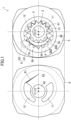
- FIG. 1 is an exploded view where the front cover 6 is removed from the gear housing 5.
- the shaft 2 extends laterally in FIG. 2 .
- the shaft 2 includes a first shaft 21 and a second shaft 22.
- the first shaft 21 and the second shaft 22 are coaxially coupled and integrally rotated.
- the second shaft 22 protrudes from the housing 10 and is connected to a prime mover (not shown).
- the prime mover is, for example, an electric motor.
- the pinion gear 3 is integrally formed in a middle position of the first shaft 21.
- the pinion gear 3 and the shaft 2 are coaxial.
- the pinion gear 3 rotates together with the shaft 2.
- the pinion gear 3 includes external teeth 31.
- the ring gear 4 meshes with the pinion gear 3.
- the ring gear 4 is eccentric to the shaft 2.
- C1 represents the rotation axis of the pinion gear 3
- C2 represents the rotation axis of the ring gear 4.
- the ring gear 4 has the inner circumferential surface provided with internal teeth 41. In the right area of the right figure of FIG. 1 , part of the external teeth 31 of the pinion gear 3 mesh with part of the internal teeth 41 of the ring gear 4.
- the gear housing 5 houses the pinion gear 3 and the ring gear 4.
- the gear housing 5 has an inner hole 53. An end of the first shaft 21 is located in the inner hole 53.
- the pinion gear 3 and the ring gear 4 are rotatably housed in the gear housing 5.
- the gear housing 5 has a sliding surface 51 on which the outer circumferential surface 42 of the ring gear 4 slides.
- the outer circumferential surface 42 of the ring gear 4 has a circular transverse section.
- the sliding surface 51 of the gear housing 5 also has a circular transverse section.
- the sliding surface 51 is eccentric to the shaft 2.
- the gear housing 5 has a first support surface 52 orthogonal to the sliding surface 51.
- the sliding surface 51 and the first support surface 52 form a space 50 that houses the pinion gear 3 and the ring gear 4.
- the space 50 is open to the left in FIG. 2 .
- a first side surface 32 of the pinion gear 3 and a first side surface 43 of the ring gear 4 are supported by the first support surface 52 of the gear housing 5 and slide on the first support surface 52.
- the first side surface 32 of the pinion gear 3 is orthogonal to the rotation axis C1 of the pinion gear 3 and is the right side surface in FIG. 2 .
- the first side surface 43 of the ring gear 4 is orthogonal to the rotation axis C2 of the ring gear 4 and is the right side surface in FIG. 2 .
- the front cover 6 is adjacent to the gear housing 5.
- the front cover 6 and the gear housing 5 are fixed together, thereby being integrated together.
- the front cover 6 includes a second support surface 61 which is in contact with the gear housing 5 and which closes the space 50.
- a second side surface 33 of the pinion gear 3 and a second side surface 44 of the ring gear 4 are supported by the second support surface 61 of the front cover 6 and slide on the second support surface 61.
- the second side surface 33 of the pinion gear 3 is orthogonal to the rotation axis C1 of the pinion gear 3 and is the left side surface in FIG. 2 .
- the second side surface 44 of the ring gear 4 is orthogonal to the rotation axis C2 of the ring gear 4 and is the left side surface in FIG. 2 .
- the front cover 6 has a support hole 62 which the shaft 2 passes though.
- the shaft 2 is rotatably supported by the front cover 6 and the gear housing 5 via a bearing 63 and a support member 64.
- the opening of the support hole 62 is closed by a sealing member 621.
- the front cover 6 and the gear housing 5 also have a discharge port 12.
- the discharge port 12 is a port for discharging the operation oil from the space 50 inside the housing 10. As shown in FIG. 2 , the outlet of the discharge port 12 is open to the outer circumferential surface of the gear housing 5.
- the inlet of the suction port 11 and the outlet of the discharge port 12 may have different orientations as shown in FIG. 2 , or may have the same orientation although not shown.
- the inlet of the discharge port 12 is open to each of the second support surface 61 of the front cover 6 and the first support surface 52 of the gear housing 5. As shown in FIG. 1 , the inlet of the discharge port 12 is opposite the suction port 11 with the shaft 2 sandwiched therebetween, and extends in the circumferential direction along the direction of rotation of the shaft 2.
- the gear housing 5 includes a crescent 54.
- the crescent 54 is located at a place where the pinion gear 3 and the ring gear 4 are disengaged from each other.
- the crescent 54 separates a second region and a first region, which will be described later.
- the crescent 54 extends in the circumferential direction in a predetermined angle range along the direction of rotation of the shaft 2. As shown in FIG. 1 , the crescent 54 is in a crescent shape when viewed along the axis of the shaft 2.
- the crescent 54 has two arc walls, namely, a first arc wall 541 and a second arc wall 542, each standing on the first support surface 52 of the gear housing 5.
- the tips of the external teeth 31 of the pinion gear 3 substantially abut onto the first arc wall 541 of the crescent 54.
- the tips of the internal teeth 41 of the ring gear 4 substantially abut onto the second arc wall 542 of the crescent 54.
- Both the first arc wall 541 and the second arc wall 542 are fixed walls that do not move toward the external teeth 31 and the internal teeth 41.
- the inside of the housing 10 can be divided into a first region in which the suction port 11 is open, a second region in which the discharge port 12 is open, and a third region between the first region and the second region in which the crescent 54 is provided, where the three regions are provided in the circumferential direction about the rotation axis C2 of the ring gear 4.
- the first region is a low-pressure region
- the second region is a high-pressure region.
- the operation oil is sucked from the suction port 11 into the spaces between the external teeth 31 and the internal teeth 41.
- the sucked operation oil is carried from the first region to the second region through the third region in accordance with the rotation of the pinion gear 3 and the ring gear 4.
- the internal gear pump 1 includes a high-pressure oil supply portion 8.
- the high-pressure oil supply portion 8 supplies high-pressure operation oil to the gap between the outer circumferential surface 42 of the ring gear 4 and the sliding surface 51 of the gear housing 5.
- the high-pressure oil supply portion 8 is shown in FIG. 1 only.
- the high-pressure oil supply portion 8 supplies the high-pressure operation oil to press and move the ring gear 4 from the outer periphery of the third region toward the rotation axis C2.
- the tips of the of tooth of the ring gear 4 are pressed onto the second arc wall 542 of the crescent 54, and thus operation oil leaks less from the high pressure side to the low pressure side in the housing 10.
- the high-pressure oil supply portion 8 includes an inlet 81 that is open to the sliding surface 51 and a supply passage 82 that connects the discharge port 12 and the inlet 81.
- the inlet 81 is located in the third region. More specifically, the inlet 81 faces the crescent 54 in the radial direction with the ring gear 4 sandwiched therebetween.
- the inlet 81 introduces part of the high-pressure operation oil discharged from the discharge port 12 into the housing 10.
- the inlet 81 is preferably located to face the crescent 54.
- the inlet 81 is preferably located in the high-pressure region, which is one of two equally divided regions, the low-pressure region and the high-pressure region, of the third region.
- the supply passage 82 is formed in the gear housing 5.
- the supply passage 82 connects the discharge port 12 that is open to the first support surface 52 of the gear housing 5 with the inlet 81.
- the supply passage may be formed in the front cover 6 and the gear housing 5 so as to connect the discharge port 12 that is open to the second support surface 61 of the front cover 6 with the inlet 81.
- the supply passage may connect the discharge port 12 that is open to the first support surface 52 with the inlet 81, and also may connect the discharge port 12 that is open to the second support surface 61 with the inlet 81.
- part of the high-pressure operation oil in the discharge port 12 is introduced into the gap between the outer circumferential surface of the ring gear 4 and the sliding surface 51 of the gear housing 5 through the supply passage 82 and the inlet 81.
- the high-pressure operation oil presses the ring gear 4 from the outer periphery of the third region toward the rotation axis C2.
- the tips of the teeth of the ring gear 4 are pressed onto the second arc wall 542 of the crescent 54.
- the operation oil leaks less from the high pressure side to the low pressure side through the gap between the tips of the teeth of the ring gear 4 and the second arc wall 542 of the crescent 54.
- the reduction in leakage flow in the housing 10 improves the pump efficiency of the internal gear pump 1.
- the high-pressure oil supply portion 8 may include an orifice in the middle of the supply passage 82.
- the orifice adjusts the pressure of the operation oil introduced into the gap between the outer circumferential surface of the ring gear 4 and the sliding surface 51 of the gear housing 5.
- the high-pressure oil supply portion 8 may be omitted.
- the high-pressure oil supply portion 8 is not an essential element of the internal gear pump 1.
- the internal gear pump 1 When the spaces between the teeth of the pinion gear 3 and the spaces between the teeth of the ring gear 4 pass through the third region and then turn open to the discharge port 12, the internal gear pump 1 produces noise due to the pressure difference between the pressure of the discharge port 12 and the pressure of the spaces between the teeth. As the pressure difference between the pressure of the discharge port 12 and the pressure of the spaces between the teeth is larger, the pressure fluctuation is larger when the spaces between the teeth are open to the discharge port 12, and thus the internal gear pump produces larger noise.
- the internal gear pump 1 has a pressure transmission oil path 91 for reducing the noise.
- the pressure transmission oil path 91 raises in advance in the third region, the pressure of the operation oil confined in the spaces between the teeth, thereby reducing the pressure difference between the pressure of the discharge port 12 and the pressure of the spaces between the teeth. If the pressure difference is small, the pressure fluctuation is small when the spaces between the teeth are open to the discharge port 12, and thus the internal gear pump produces less noise.
- the pressure transmission oil path 91 is formed as a recess from the second support surface 61 of the front cover 6.
- the pressure transmission oil path 91 formed in the front cover 6 is shown by a long-dashed double-short-dashed line, where the pressure transmission oil path 91 is projected onto the gear housing 5 to clearly describe the positional relationship among the pressure transmission oil path 91, the ring gear 4, and the crescent 54.
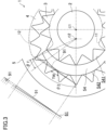
- the pressure transmission oil path 91 is a groove formed on the second support surface 61. As shown in FIG. 3 , the shape of the transverse section of the pressure transmission oil path 91 is triangular. The shape of the transverse section of the pressure transmission oil path 91 is not necessarily triangular. The shape of the transverse section may be quadrangular, for example.
- the pressure transmission oil path 91 extends straight from the edge of the discharge port 12 toward the low pressure side of the third region. As shown in FIG. 3 , the depth of the pressure transmission oil path 91 is gradually shallower as its distance from the discharge port 12 is longer, and the width of the pressure transmission oil path 91 is gradually narrower as its distance from the discharge port 12 is longer.
- the depth of the pressure transmission oil path may be constant, and the width of the pressure transmission oil path may be constant.
- the pressure transmission oil path 91 overlaps the spaces between the teeth of the ring gear 4 when viewed in the direction of the rotation axis C2 of the ring gear 4, in other words, when viewed in the right figure of FIG. 1 or FIG. 3 .
- the pressure transmission oil path 91 is straight, whereas the crescent 54 is crescent.
- the base end of the pressure transmission oil path 91 i.e., the end of the pressure transmission oil path 91 that is connected with the discharge port 12
- the middle portion of the pressure transmission oil path 91 is located near the second arc wall 542 of the crescent 54.
- the tip end of the pressure transmission oil path 91 is located away from the second arc wall 542 of the crescent 54.
- the pressure transmission oil path 91 can extend without being interfered with by the crescent 54.
- the spaces between the teeth of the ring gear 4 are closed because the tips of the teeth of the ring gear 4 are pressed onto the second arc wall 542 of the crescent 54.
- the pressure transmission oil path 91 communicates with the spaces between teeth of the ring gear 4 in the direction orthogonal to the plane of FIG. 1 or 3 . Part of the high-pressure operation oil in the discharge port 12 flows into the spaces between the teeth of the ring gear 4 through the pressure transmission oil path 91, thereby raising the pressure of those spaces.
- the inventors of the present invention measured the real pressure in the housing 10, confirming that if the pressure transmission oil path 91 is absent, the pressure of the spaces between the teeth of the ring gear 4 decreases with respect to the discharge pressure in the region closer to the ring gear 4, which is one of the region closer to the pinion gear 3 and the region closer to the ring gear 4 that sandwich the crescent 54 in the third region, whereas if the pressure transmission oil path 91 is present, the pressure of the same spaces increases. Since the pressure of the spaces between the teeth of the ring gear 4 increases in advance in the third region, the pressure difference between the pressure of the discharge port 12 and the pressure of the spaces between the teeth decreases. Since the pressure fluctuation is smaller when those spaces are open to the discharge port 12, the internal gear pump 1 produces less noise. The inventors of the present invention studied and confirmed that the pressure transmission oil path 91 contributes to decrease in the noise level and that, as the discharge pressure of the internal gear pump 1 is higher, the noise level is more improved.
- the internal gear pump 1 is formed only in the region closer to the ring gear 4, which is one of the region closer to the pinion gear 3 and the region closer to the ring gear 4 that sandwich the crescent 54 in the third region.
- the pressure transmission oil path is not formed in the region closer to the pinion gear 3.
- the inventors of the present invention studied and found that the pressure of the spaces between the teeth of the pinion gear 3 is relatively high even if the pressure transmission oil path is absent, and that the pressure is higher than or equal to the pressure in the region closer the ring gear 4 where the pressure transmission oil path 91 is present.
- the pressure fluctuation is relatively small when the spaces between the teeth of the pinion gear 3 are open to the discharge port 12. This is because the crescent 54 is configured so that the first arc wall 541 and the second arc wall 542 are not movable, and because there are minute gaps between the tips of the teeth of the pinion gear 3 and the first arc wall 541. In the region closer to the pinion gear 3, those gaps allow leakage flow from the discharge port 12 to the spaces between the teeth of the pinion gear 3. As a result, in the third region, the pressure of the spaces between the teeth of the pinion gear 3 is relatively high.
- the pressure of the spaces between the teeth of the pinion gear 3 is relatively high, the pressure of the space does not increase any more even if the pressure transmission oil path is present in the region closer to the pinion gear 3. Thus, the internal gear pump 1 is unlikely to reduce noise. On the other hand, if the pressure transmission oil path is present, the leakage flow increases accordingly. Thus, the pump efficiency of the internal gear pump 1 might be lowered.
- the pressure transmission oil path 91 is present only in the region closer to the ring gear 4 in the housing, whereas the pressure transmission oil path is absent in the region closer to the pinion gear 3.
- the internal gear pump 1 achieves both less noise and higher pump efficiency.
- the length of the pressure transmission oil path 91 is determined by considering at which position of the third region in the housing 10 the tip end of the pressure transmission oil path 91 is located.
- the length referred to herein of the pressure transmission oil path 91 is not the length along the straight pressure transmission oil path 91.
- the pressure transmission oil path 91 has a function of raising the pressure of the spaces between the teeth of the ring gear 4 before those spaces communicate with the discharge port 12. If the pressure transmission oil path 91 is too short, it is difficult to raise in advance the pressure of the spaces between the teeth of the ring gear 4 before those spaces communicate with the discharge port 12. There is the minimum length of the pressure transmission oil path 91 that allows the pressure transmission oil path 91 to perform that function.
- the tip end of the pressure transmission oil path 91 is located away from the edge of the discharge port 12 by an angle ⁇ 1 or more with respect to the rotation axis C2 of the ring gear 4, where the angle ⁇ 1 is equivalent to the tooth width TW of the ring gear 4. If the pressure transmission oil path 91 extends to a position of the angle ⁇ 1 or more, the pressure transmission oil path 91 allows the discharge port 12 and the spaces between the teeth to communicate with each other beyond at least one of the teeth of the ring gear 4.
- the pressure transmission oil path 91 can supply the high-pressure operation oil into the spaces between the teeth before those spaces reach the discharge port 12. That is, the pressure transmission oil path 91 can raise in advance the pressure of the spaces between the teeth of the ring gear 4 before those spaces communicate with the discharge port 12.
- Lengthening the pressure transmission oil path 91 is advantageous in raising the pressure of the spaces between the teeth of the ring gear 4.
- the pressure transmission oil path 91 that is lengthened to a certain degree or more cannot raise the pressure of the spaces between the teeth.
- leakage flow in the housing 10 increases.
- the tip end of the pressure transmission oil path 91 is located within a range of an angle ⁇ 2 or less formed from the edge of the discharge port 12 to the middle position of the crescent 54. In the drawing, the tip end of the pressure transmission oil path 91 is located in the middle position of the crescent 54.
- the middle position of the crescent 54 is a circumferentially middle position of the crescent 54 extending in the circumferential direction from the discharge port 12 to the suction port 11.
- the pressure transmission oil path 91 that is not too long can sufficiently raise the pressure of the spaces between the teeth of the ring gear 4 and can reduce an increase in the leakage flow.
- the pressure transmission oil path 91 is formed on the second support surface 61 of the front cover 6.
- the pressure transmission oil path 91 may be formed as a recess from the first support surface 52 of the gear housing 5.
- the pressure transmission oil path 91 may be formed on both the second support surface 61 of the front cover 6 and the first support surface 52 of the gear housing 5.
- FIG. 4 shows a pressure transmission oil path 92 that is curved. Similarly to the pressure transmission oil path 91, the pressure transmission oil path 92 is formed on the second support surface 61 of the front cover 6. In FIG. 4 , similarly to FIG. 3 , the pressure transmission oil path 92 formed in the front cover 6 is also projected onto the gear housing 5.
- the pressure transmission oil path 92 extends in an arc shape along the curve of the second arc wall 542 of the crescent 54. When viewed in the direction of the rotation axis C2 of the ring gear 4, the pressure transmission oil path 92 overlaps the spaces between the teeth of the ring gear 4. The pressure transmission oil path 92 communicates with the spaces between the teeth of the ring gear 4. Since the pressure of the spaces between the teeth of the ring gear 4 increases in the third region, the pressure difference between the pressure of the discharge port 12 and the pressure of the spaces between the teeth is small when the spaces are open to the discharge port 12. Thus, the internal gear pump 1 produces less noise.
- the arc shape of the pressure transmission oil path 92 of FIG. 4 is a mere example.
- the curved pressure transmission oil path 92 is not limited to an arc shape.
- the depth of the pressure transmission oil path 92 may be gradually shallower as its distance from the discharge port 12 is longer, or may be constant.
- the width of the pressure transmission oil path 92 may be gradually narrower as its distance from the discharge port 12 is longer, or may be constant.
- the location of the tip end of the pressure transmission oil path 92 can be set within the above-described range of ⁇ 1 or more and ⁇ 2 or less as necessary.
- the pressure transmission oil path 92 may be formed on the first support surface 52 of the gear housing 5.
- the pressure transmission oil path formed on the first support surface 52 and/or the second support surface 61 may be bent at its middle position.
- FIG. 5 is a perspective view of the internal gear pump 1 where the front cover 6 is removed.
- This internal gear pump 1 includes a pressure transmission oil path 93 formed on the crescent 54.
- the pressure transmission oil path 93 is formed on the upper end of the second arc wall 542 of the crescent 54.
- the pressure transmission oil path 93 is formed by cutting out the surface of the crescent 54.
- the upper end referred to herein is the end of the crescent 54 that stands on the first support surface 52 of the gear housing 5, where the end is located opposite the first support surface 52.
- the upper end of the second arc wall 542 is the end abutting on the second support surface 61 of the front cover 6.
- the pressure transmission oil path 93 extends from the end of the crescent 54 on the high pressure side (i.e., the left end in FIG. 5 ) to the middle position of the crescent 54.
- the pressure transmission oil path 93 communicates with the discharge port 12 that is open to the second support surface 61 of the front cover 6.
- the length of the pressure transmission oil path 93 can be set within the above-described range of ⁇ 1 or more and ⁇ 2 or less as necessary.
- the width and depth of the pressure transmission oil path 93 are gradually narrower and shallower, respectively, as its distance from the discharge port 12 is longer.
- the width and depth of the pressure transmission oil path 93 may be constant.
- the pressure transmission oil path 93 formed on the crescent 54 also allows the spaces between the teeth of the ring gear 4 and the discharge port 12 to communicate with each other. Since the pressure of the spaces between the teeth of the ring gear 4 increases in the third region, the pressure difference between the pressure of the discharge port 12 and the pressure of the spaces between the teeth is small when the spaces are open to the discharge port 12. Then the pressure fluctuation is reduced, and thus the internal gear pump 1 produces less noise.
- the pressure transmission oil path formed on the crescent 54 is not necessarily formed on the upper end of the crescent 54.
- the pressure transmission oil path may be formed on a vertically middle position of the second arc wall 542 of the crescent 54.
- the pressure transmission oil path may be formed on the lower end of the crescent 54.
Landscapes
- Engineering & Computer Science (AREA)
- Mechanical Engineering (AREA)
- General Engineering & Computer Science (AREA)
- Rotary Pumps (AREA)
Abstract
Description
- The technique disclosed herein relates to an internal gear pump.
-
Patent Document 1 discloses an internal gear pump (1). This internal gear pump (1) includes a separation member (7) (a so-called "crescent"). The tips of teeth of an internal gear (2) and the tips of teeth of a pinion (3) abut onto the separation member (7). - The separation member (7) includes an inner part (13), an outer part (14), and a spring (16). The spring (16) presses the inner part (13) onto the tips of the teeth of the pinion (3), and presses the outer part (14) onto the tips of the teeth of the internal gear (2). The separation member (7) has a movable structure. The movable separation member (7) reduces leakage flow in the internal gear pump (1) and increases the pump efficiency.
- The separation member (7) also includes a middle space (17) between the inner part (13) and the outer part (14). The middle space (17) communicates with a pressurization region (9) of the internal gear pump (1). The inner part (13) and the outer part (14) have a penetration part (19). The penetration part (19) radially penetrates the inner part (13) and the outer part (14), and allows the middle space (17) to communicate with the spaces between the teeth of the pinion (3) and the teeth of the internal gear (2). When the internal gear pump (1) is operated, the pressure of the middle space (17) is the same as that of the pressurization region (9), and thus the pressure of the spaces between the teeth of the pinion (3) and the teeth of the internal gear (2) increase through the penetration part (19). The high pressure of the spaces between the teeth reduces rapid pressure changes at the pump discharge part and then reduces noise of the internal gear pump (1).
- Patent Document 1:
Japanese Patent No. 6297277 - The penetration part (19) of the internal gear pump (1) of
Patent Document 1 supplies liquid from the pump discharge part to both the gap between the separation member (7) and the pinion (3) and the gap between the separation member (7) and the internal gear (2) in order to reduce noise. However, this supply of liquid increases leakage flow in the internal gear pump (1). A conventional internal gear pump produces less noise but operates less efficiently. - According to the technique disclosed herein, the internal gear pump achieves both less noise and less reduction in its efficiency.
- The internal gear pump (1) of
Patent Document 1 includes a crescent having a movable structure. Unlike this, internal gear pumps including a crescent with an immovable structure are known. - The inventors of the present invention studied and newly found that if the crescent has an immovable structure, the pressure of the spaces between the teeth of the pinion gear is relatively high. This seems because the wall of the crescent is not pressed onto the external teeth of the pinion gear so that minute gaps are present between the teeth of the pinion gear and the wall of the crescent. The minute gaps allow leakage flow from the discharge port, and this leakage flow raises the pressure of the spaces between the teeth of the pinion gear.
- Even if, for the purpose of noise reduction, the internal gear pump has an extra structure for supplying operation oil from the discharge port to the spaces between the teeth of the pinion gear, this only leads to more leakage flow and less pump efficiency, and the internal gear pump substantially fails to reduce noise.
- Thus, the inventors of the present invention decided to provide in the housing only the pressure transmission oil path extending from the discharge port to the spaces between the teeth of the ring gear in the internal gear pump including a crescent with an immovable structure.
- Specifically, the technique disclosed herein relates to an internal gear pump. This internal gear pump includes: a pinion gear including external teeth; a ring gear including internal teeth that mesh with the external teeth; a housing including a suction port and a discharge port and configured to rotatably house the pinion gear and the ring gear; and a crescent located at a position where the pinion gear and the ring gear are disengaged from each other, and including a first arc wall onto which the external teeth abut and a second arc wall onto which the internal teeth abut, wherein the first arc wall and the second arc wall are both fixed walls that do not move toward the external teeth and the internal teeth; in the housing, a pressure transmission oil path extending from the discharge port is formed only in a region closer to the ring gear, which is one of a region closer to the pinion gear and the region closer to the ring gear that sandwich the crescent; and the pressure transmission oil path allows the discharge port and spaces between the teeth of the ring gear to communicate with each other.
- The space between the teeth of the ring gear is a space between teeth adjacent to each other of the ring gear.
- This internal gear pump includes a crescent with an immovable structure. As described above, the pressure of the spaces between the teeth of the pinion gears is relatively high.
- In the housing, the pressure transmission oil path is formed only in a region closer to the ring gear, which is one of a region closer to the pinion gear and the region closer to the ring gear that sandwich the crescent. The pressure transmission oil path extending from the discharge port distributes part of the operation oil from the discharge port to the low pressure side. The pressure transmission oil path allows the discharge port and the spaces between the teeth of the ring gear to communicate with each other, and thus part of the high-pressure operation oil in the discharge port flows into the spaces between the teeth of the ring gear. The pressure of the spaces between the teeth of the ring gear increases. The high pressure of the spaces between the teeth reduces rapid pressure changes at the discharge port.
- The pressure of the spaces between the teeth of the pinion gear is high even if the pressure transmission oil path is absent. Also, in the region closer to the pinion gear, rapid pressure changes at the discharge port are reduced.
- The pressure transmission oil path formed only in the region closer to the ring gear, which is one of the regions that sandwich the crescent with an immovable structure, reduces rapid pressure changes at the discharge port in both the region closer to the ring gear and the region closer to the pinion gear. Thus, the internal gear pump produces less noise.
- The pressure transmission oil path promotes leakage flow of the internal gear pump, but the pressure transmission oil path is formed only in the region closer to the ring gear and is not formed in the region closer to the pinion gear. Thus, the internal gear pump achieves less increase in the leakage flow. Accordingly, the pump efficiency is less reduced.
- Thus, the internal gear pump achieves both less noise and less reduction in its efficiency.
- The housing may have a sliding surface on which an outer circumferential surface of the ring gear slides, the internal gear pump may include a high-pressure oil supply portion configured to supply high-pressure operation oil to a gap between the outer circumferential surface and the sliding surface through an inlet that is open to the sliding surface, and the inlet may be located opposite the crescent with the ring gear sandwiched therebetween.
- The high-pressure oil supply portion supplies high-pressure operation oil to the gap between the outer circumferential surface of the ring gear and the sliding surface of the housing. The supplied high-pressure operation oil presses the ring gear toward the rotation axis of the ring gear. Since the inlet is located opposite the crescent with the ring gear sandwiched therebetween, the internal teeth of the ring gear are pressed onto the second arc wall of the crescent. Then, less operation oil leaks from a gap between the internal teeth and the second arc wall. Thus, the high-pressure oil supply portion increases the pump efficiency of the internal gear pump.
- The internal teeth of the ring gear being pressed onto the second arc wall of the crescent increases the pump efficiency, but reduces a pressure increase in the spaces between the teeth of the ring gear due to leakage flow from the discharge port. If the pressure of the spaces between the teeth of the ring gear is low, the internal gear pump produces more noise.
- The internal gear pump includes the pressure transmission oil path formed only in the region closer to the ring gear in the housing. As described above, the pressure transmission oil path raises the pressure of the spaces between the teeth of the ring gear. Combination of the high-pressure oil supply portion and the pressure transmission oil path closer to the ring gear enables the internal gear pump to achieve both less noise and less reduction in its efficiency at a high level.
- The housing may include a first support surface and a second support surface, each supporting a respective one of two side surfaces of the ring gear, where the two side surfaces of the ring gear are orthogonal to a rotation axis, the discharge port may be formed in each of the first support surface and the second support surface, the pressure transmission oil path may be formed as a recess from the first support surface, the second support surface, or both the first support surface and the second support surface, and the pressure transmission oil path may overlap the spaces between the teeth of the ring gear when viewed in a direction of the rotation axis.
- The pressure transmission oil path formed on the first support surface and/or the second support surface overlaps the spaces between the teeth of the ring gear when viewed in the direction of the rotation axis, which enables the operation oil to be supplied from the discharge port to the spaces between the teeth of the ring gear. Thus, the pressure of the spaces between the teeth of the ring gear increases.
- The transverse section of the pressure transmission oil path formed on the first support surface and/or the second support surface may be triangular. The transverse section of the pressure transmission oil path formed on the first support surface and/or the second support surface may be quadrangular.
- The pressure transmission oil path may be a groove formed on the first support surface and/or the second support surface.
- The pressure transmission oil path may be straight. The pressure transmission oil path may be curved.
- The pressure transmission oil path may be formed as a recess from the second arc wall of the crescent.
- The pressure transmission oil path may be formed by cutting out the surface of the crescent.
- The pressure transmission oil path formed on the second arc wall of the crescent communicates with the spaces between the teeth of the ring gear. The pressure transmission oil path can supply the operation oil from the discharge port to the spaces between the teeth of the ring gear. Thus, the pressure of the spaces between the teeth of the ring gear increases.
- The depth of the pressure transmission oil path may be gradually shallower as its distance from the discharge port is longer. The depth of the pressure transmission oil path may be constant. The width of the pressure transmission oil path may be gradually narrower as its distance from the discharge port is longer. The width of the pressure transmission oil path may be constant.
a tip end of the pressure transmission oil path may be located away from an edge of the discharge port by an angle θ1 or more with respect to a rotation axis of the ring gear, where the angle θ1 is equivalent to a tooth width of the ring gear; and also be located within a range of an angle θ2 or less formed from the discharge port to a middle position of the crescent extending to the discharge port. - The pressure transmission oil path having an appropriate length enables the internal gear pump to achieve both less noise and less reduction in its efficiency at a high level.
- If the tip end of the pressure transmission oil path is located at a position of the angle θ1 or less, the pressure transmission oil path is too short. That is, the pressure transmission oil path that is too short cannot raise the pressure of the spaces between the teeth of the ring gear before the spaces turn open to the discharge port.
- Even if the tip end of the pressure transmission oil path is located at a position of the angle of over θ2, noise is reduced at substantially the same level as if the angle θ2 or less. On the other hand, the pressure transmission oil path that is too long leads to more leakage flow of the operation oil and less pump efficiency.
- If the tip end of the pressure transmission oil path is located within a range of the angle of θ1 or more and θ2 or less, both less noise and less reduction in the pump efficiency can be achieved.
- The internal gear pump achieves both less noise and less reduction in its efficiency.
-
-
FIG. 1 is an exploded view of an internal gear pump. -
FIG. 2 is a cross-sectional view of the internal gear pump. -
FIG. 3 shows a pressure transmission oil path. -
FIG. 4 is a variation of the pressure transmission oil path. -
FIG. 5 is another variation of the pressure transmission oil path. - An embodiment of an internal gear pump will be described with reference to the drawings. The internal gear pump described herein is a mere example.
-
FIGS. 1 and2 show aninternal gear pump 1. Theinternal gear pump 1 includes ashaft 2, apinion gear 3, aring gear 4, agear housing 5, and afront cover 6. Thegear housing 5 and thefront cover 6 constitute ahousing 10 of theinternal gear pump 1.FIG. 1 is an exploded view where thefront cover 6 is removed from thegear housing 5. - The
shaft 2 extends laterally inFIG. 2 . Theshaft 2 includes afirst shaft 21 and asecond shaft 22. Thefirst shaft 21 and thesecond shaft 22 are coaxially coupled and integrally rotated. Thesecond shaft 22 protrudes from thehousing 10 and is connected to a prime mover (not shown). The prime mover is, for example, an electric motor. - The
pinion gear 3 is integrally formed in a middle position of thefirst shaft 21. Thepinion gear 3 and theshaft 2 are coaxial. Thepinion gear 3 rotates together with theshaft 2. Thepinion gear 3 includesexternal teeth 31. - The
ring gear 4 meshes with thepinion gear 3. Thering gear 4 is eccentric to theshaft 2. InFIG. 1 , C1 represents the rotation axis of thepinion gear 3, and C2 represents the rotation axis of thering gear 4. Thering gear 4 has the inner circumferential surface provided withinternal teeth 41. In the right area of the right figure ofFIG. 1 , part of theexternal teeth 31 of thepinion gear 3 mesh with part of theinternal teeth 41 of thering gear 4. - The
gear housing 5 houses thepinion gear 3 and thering gear 4. Thegear housing 5 has aninner hole 53. An end of thefirst shaft 21 is located in theinner hole 53. - The
pinion gear 3 and thering gear 4 are rotatably housed in thegear housing 5. Thegear housing 5 has a slidingsurface 51 on which the outercircumferential surface 42 of thering gear 4 slides. The outercircumferential surface 42 of thering gear 4 has a circular transverse section. The slidingsurface 51 of thegear housing 5 also has a circular transverse section. The slidingsurface 51 is eccentric to theshaft 2. - The
gear housing 5 has afirst support surface 52 orthogonal to the slidingsurface 51. The slidingsurface 51 and thefirst support surface 52 form aspace 50 that houses thepinion gear 3 and thering gear 4. Thespace 50 is open to the left inFIG. 2 . Afirst side surface 32 of thepinion gear 3 and afirst side surface 43 of thering gear 4 are supported by thefirst support surface 52 of thegear housing 5 and slide on thefirst support surface 52. Thefirst side surface 32 of thepinion gear 3 is orthogonal to the rotation axis C1 of thepinion gear 3 and is the right side surface inFIG. 2 . Thefirst side surface 43 of thering gear 4 is orthogonal to the rotation axis C2 of thering gear 4 and is the right side surface inFIG. 2 . - The
front cover 6 is adjacent to thegear housing 5. Thefront cover 6 and thegear housing 5 are fixed together, thereby being integrated together. Thefront cover 6 includes asecond support surface 61 which is in contact with thegear housing 5 and which closes thespace 50. Asecond side surface 33 of thepinion gear 3 and asecond side surface 44 of thering gear 4 are supported by thesecond support surface 61 of thefront cover 6 and slide on thesecond support surface 61. Thesecond side surface 33 of thepinion gear 3 is orthogonal to the rotation axis C1 of thepinion gear 3 and is the left side surface inFIG. 2 . Thesecond side surface 44 of thering gear 4 is orthogonal to the rotation axis C2 of thering gear 4 and is the left side surface inFIG. 2 . - The
front cover 6 has asupport hole 62 which theshaft 2 passes though. Theshaft 2 is rotatably supported by thefront cover 6 and thegear housing 5 via abearing 63 and asupport member 64. The opening of thesupport hole 62 is closed by a sealingmember 621. - The
front cover 6 and thegear housing 5 have asuction port 11. Thesuction port 11 is a port for sucking the operation oil into thespace 50 inside thehousing 10. As shown inFIG. 2 , an inlet of thesuction port 11 is open to the outer circumferential surface of thefront cover 6. As shown inFIGS. 1 and2 , the outlet of thesuction port 11 is open to each of thesecond support surface 61 of thefront cover 6 and thefirst support surface 52 of thegear housing 5. The outlet of thesuction port 11 also extends in the circumferential direction along the direction of rotation of theshaft 2. - The
front cover 6 and thegear housing 5 also have adischarge port 12. Thedischarge port 12 is a port for discharging the operation oil from thespace 50 inside thehousing 10. As shown inFIG. 2 , the outlet of thedischarge port 12 is open to the outer circumferential surface of thegear housing 5. The inlet of thesuction port 11 and the outlet of thedischarge port 12 may have different orientations as shown inFIG. 2 , or may have the same orientation although not shown. - The inlet of the
discharge port 12 is open to each of thesecond support surface 61 of thefront cover 6 and thefirst support surface 52 of thegear housing 5. As shown inFIG. 1 , the inlet of thedischarge port 12 is opposite thesuction port 11 with theshaft 2 sandwiched therebetween, and extends in the circumferential direction along the direction of rotation of theshaft 2. - The
gear housing 5 includes acrescent 54. Thecrescent 54 is located at a place where thepinion gear 3 and thering gear 4 are disengaged from each other. Thecrescent 54 separates a second region and a first region, which will be described later. - The
crescent 54 extends in the circumferential direction in a predetermined angle range along the direction of rotation of theshaft 2. As shown inFIG. 1 , thecrescent 54 is in a crescent shape when viewed along the axis of theshaft 2. Thecrescent 54 has two arc walls, namely, afirst arc wall 541 and asecond arc wall 542, each standing on thefirst support surface 52 of thegear housing 5. - The tips of the
external teeth 31 of thepinion gear 3 substantially abut onto thefirst arc wall 541 of thecrescent 54. The tips of theinternal teeth 41 of thering gear 4 substantially abut onto thesecond arc wall 542 of thecrescent 54. Both thefirst arc wall 541 and thesecond arc wall 542 are fixed walls that do not move toward theexternal teeth 31 and theinternal teeth 41. - The inside of the
housing 10 can be divided into a first region in which thesuction port 11 is open, a second region in which thedischarge port 12 is open, and a third region between the first region and the second region in which thecrescent 54 is provided, where the three regions are provided in the circumferential direction about the rotation axis C2 of thering gear 4. The first region is a low-pressure region, and the second region is a high-pressure region. - Next, operation of the
internal gear pump 1 will be described briefly. When the prime mover makes theshaft 2 rotated clockwise in the right figure ofFIG. 1 , thepinion gear 3 and thering gear 4 each rotate in the direction from the first region to the second region through the third region. - In the first region in the
housing 10, as theexternal teeth 31 of thepinion gear 3 and theinternal teeth 41 of thering gear 4 having meshed with each other are separated from each other, the operation oil is sucked from thesuction port 11 into the spaces between theexternal teeth 31 and theinternal teeth 41. The sucked operation oil is carried from the first region to the second region through the third region in accordance with the rotation of thepinion gear 3 and thering gear 4. - In the second region in the
housing 10, theexternal teeth 31 of thepinion gear 3 and theinternal teeth 41 of thering gear 4 having been separated from each other gradually approach each other and eventually mesh with each other. Accordingly, the operation oil is discharged from the gap between theexternal teeth 31 and theinternal teeth 41 through thedischarge port 12. - The
internal gear pump 1 includes a high-pressureoil supply portion 8. The high-pressureoil supply portion 8 supplies high-pressure operation oil to the gap between the outercircumferential surface 42 of thering gear 4 and the slidingsurface 51 of thegear housing 5. The high-pressureoil supply portion 8 is shown inFIG. 1 only. - The high-pressure
oil supply portion 8 supplies the high-pressure operation oil to press and move thering gear 4 from the outer periphery of the third region toward the rotation axis C2. The tips of the of tooth of thering gear 4 are pressed onto thesecond arc wall 542 of thecrescent 54, and thus operation oil leaks less from the high pressure side to the low pressure side in thehousing 10. - The high-pressure
oil supply portion 8 includes aninlet 81 that is open to the slidingsurface 51 and asupply passage 82 that connects thedischarge port 12 and theinlet 81. - As shown in
FIG. 1 , theinlet 81 is located in the third region. More specifically, theinlet 81 faces thecrescent 54 in the radial direction with thering gear 4 sandwiched therebetween. Theinlet 81 introduces part of the high-pressure operation oil discharged from thedischarge port 12 into thehousing 10. In order to efficiently press the tips of the teeth of thering gear 4 onto thecrescent 54, theinlet 81 is preferably located to face thecrescent 54. For the high-pressure operation oil introduced into thehousing 10 to flow less into the low-pressure first region, theinlet 81 is preferably located in the high-pressure region, which is one of two equally divided regions, the low-pressure region and the high-pressure region, of the third region. - The
supply passage 82 is formed in thegear housing 5. Thesupply passage 82 connects thedischarge port 12 that is open to thefirst support surface 52 of thegear housing 5 with theinlet 81. The supply passage may be formed in thefront cover 6 and thegear housing 5 so as to connect thedischarge port 12 that is open to thesecond support surface 61 of thefront cover 6 with theinlet 81. The supply passage may connect thedischarge port 12 that is open to thefirst support surface 52 with theinlet 81, and also may connect thedischarge port 12 that is open to thesecond support surface 61 with theinlet 81. - As described above, when the
internal gear pump 1 is operated, part of the high-pressure operation oil in thedischarge port 12 is introduced into the gap between the outer circumferential surface of thering gear 4 and the slidingsurface 51 of thegear housing 5 through thesupply passage 82 and theinlet 81. The high-pressure operation oil presses thering gear 4 from the outer periphery of the third region toward the rotation axis C2. The tips of the teeth of thering gear 4 are pressed onto thesecond arc wall 542 of thecrescent 54. In the third region, the operation oil leaks less from the high pressure side to the low pressure side through the gap between the tips of the teeth of thering gear 4 and thesecond arc wall 542 of thecrescent 54. The reduction in leakage flow in thehousing 10 improves the pump efficiency of theinternal gear pump 1. - The high-pressure
oil supply portion 8 may include an orifice in the middle of thesupply passage 82. The orifice adjusts the pressure of the operation oil introduced into the gap between the outer circumferential surface of thering gear 4 and the slidingsurface 51 of thegear housing 5. - In the
internal gear pump 1, the high-pressureoil supply portion 8 may be omitted. The high-pressureoil supply portion 8 is not an essential element of theinternal gear pump 1. - When the spaces between the teeth of the
pinion gear 3 and the spaces between the teeth of thering gear 4 pass through the third region and then turn open to thedischarge port 12, theinternal gear pump 1 produces noise due to the pressure difference between the pressure of thedischarge port 12 and the pressure of the spaces between the teeth. As the pressure difference between the pressure of thedischarge port 12 and the pressure of the spaces between the teeth is larger, the pressure fluctuation is larger when the spaces between the teeth are open to thedischarge port 12, and thus the internal gear pump produces larger noise. Theinternal gear pump 1 has a pressuretransmission oil path 91 for reducing the noise. - By using the high pressure of the
discharge port 12, the pressuretransmission oil path 91 raises in advance in the third region, the pressure of the operation oil confined in the spaces between the teeth, thereby reducing the pressure difference between the pressure of thedischarge port 12 and the pressure of the spaces between the teeth. If the pressure difference is small, the pressure fluctuation is small when the spaces between the teeth are open to thedischarge port 12, and thus the internal gear pump produces less noise. - In the
internal gear pump 1 ofFIGS. 1 and3 , the pressuretransmission oil path 91 is formed as a recess from thesecond support surface 61 of thefront cover 6. In the right figure ofFIG. 1 andFIG. 3 , the pressuretransmission oil path 91 formed in thefront cover 6 is shown by a long-dashed double-short-dashed line, where the pressuretransmission oil path 91 is projected onto thegear housing 5 to clearly describe the positional relationship among the pressuretransmission oil path 91, thering gear 4, and thecrescent 54. - The pressure
transmission oil path 91 is a groove formed on thesecond support surface 61. As shown inFIG. 3 , the shape of the transverse section of the pressuretransmission oil path 91 is triangular. The shape of the transverse section of the pressuretransmission oil path 91 is not necessarily triangular. The shape of the transverse section may be quadrangular, for example. - The pressure
transmission oil path 91 extends straight from the edge of thedischarge port 12 toward the low pressure side of the third region. As shown inFIG. 3 , the depth of the pressuretransmission oil path 91 is gradually shallower as its distance from thedischarge port 12 is longer, and the width of the pressuretransmission oil path 91 is gradually narrower as its distance from thedischarge port 12 is longer. The depth of the pressure transmission oil path may be constant, and the width of the pressure transmission oil path may be constant. - The pressure
transmission oil path 91 overlaps the spaces between the teeth of thering gear 4 when viewed in the direction of the rotation axis C2 of thering gear 4, in other words, when viewed in the right figure ofFIG. 1 orFIG. 3 . The pressuretransmission oil path 91 is straight, whereas thecrescent 54 is crescent. Thus, the base end of the pressure transmission oil path 91 (i.e., the end of the pressuretransmission oil path 91 that is connected with the discharge port 12) is located near the radially outermost edge of thedischarge port 12. The middle portion of the pressuretransmission oil path 91 is located near thesecond arc wall 542 of thecrescent 54. The tip end of the pressuretransmission oil path 91 is located away from thesecond arc wall 542 of thecrescent 54. The pressuretransmission oil path 91 can extend without being interfered with by thecrescent 54. - In the third region, the spaces between the teeth of the
ring gear 4 are closed because the tips of the teeth of thering gear 4 are pressed onto thesecond arc wall 542 of thecrescent 54. The pressuretransmission oil path 91 communicates with the spaces between teeth of thering gear 4 in the direction orthogonal to the plane ofFIG. 1 or3 . Part of the high-pressure operation oil in thedischarge port 12 flows into the spaces between the teeth of thering gear 4 through the pressuretransmission oil path 91, thereby raising the pressure of those spaces. The inventors of the present invention measured the real pressure in thehousing 10, confirming that if the pressuretransmission oil path 91 is absent, the pressure of the spaces between the teeth of thering gear 4 decreases with respect to the discharge pressure in the region closer to thering gear 4, which is one of the region closer to thepinion gear 3 and the region closer to thering gear 4 that sandwich thecrescent 54 in the third region, whereas if the pressuretransmission oil path 91 is present, the pressure of the same spaces increases. Since the pressure of the spaces between the teeth of thering gear 4 increases in advance in the third region, the pressure difference between the pressure of thedischarge port 12 and the pressure of the spaces between the teeth decreases. Since the pressure fluctuation is smaller when those spaces are open to thedischarge port 12, theinternal gear pump 1 produces less noise. The inventors of the present invention studied and confirmed that the pressuretransmission oil path 91 contributes to decrease in the noise level and that, as the discharge pressure of theinternal gear pump 1 is higher, the noise level is more improved. - In the
housing 10, theinternal gear pump 1 is formed only in the region closer to thering gear 4, which is one of the region closer to thepinion gear 3 and the region closer to thering gear 4 that sandwich thecrescent 54 in the third region. The pressure transmission oil path is not formed in the region closer to thepinion gear 3. - The inventors of the present invention studied and found that the pressure of the spaces between the teeth of the
pinion gear 3 is relatively high even if the pressure transmission oil path is absent, and that the pressure is higher than or equal to the pressure in the region closer thering gear 4 where the pressuretransmission oil path 91 is present. The pressure fluctuation is relatively small when the spaces between the teeth of thepinion gear 3 are open to thedischarge port 12. This is because thecrescent 54 is configured so that thefirst arc wall 541 and thesecond arc wall 542 are not movable, and because there are minute gaps between the tips of the teeth of thepinion gear 3 and thefirst arc wall 541. In the region closer to thepinion gear 3, those gaps allow leakage flow from thedischarge port 12 to the spaces between the teeth of thepinion gear 3. As a result, in the third region, the pressure of the spaces between the teeth of thepinion gear 3 is relatively high. - Since the pressure of the spaces between the teeth of the
pinion gear 3 is relatively high, the pressure of the space does not increase any more even if the pressure transmission oil path is present in the region closer to thepinion gear 3. Thus, theinternal gear pump 1 is unlikely to reduce noise. On the other hand, if the pressure transmission oil path is present, the leakage flow increases accordingly. Thus, the pump efficiency of theinternal gear pump 1 might be lowered. - Thus, in the
internal gear pump 1, the pressuretransmission oil path 91 is present only in the region closer to thering gear 4 in the housing, whereas the pressure transmission oil path is absent in the region closer to thepinion gear 3. Thus, theinternal gear pump 1 achieves both less noise and higher pump efficiency. - Next, a preferable length of the pressure
transmission oil path 91 will be studied. Here, the length of the pressuretransmission oil path 91 is determined by considering at which position of the third region in thehousing 10 the tip end of the pressuretransmission oil path 91 is located. The length referred to herein of the pressuretransmission oil path 91 is not the length along the straight pressuretransmission oil path 91. - As described above, the pressure
transmission oil path 91 has a function of raising the pressure of the spaces between the teeth of thering gear 4 before those spaces communicate with thedischarge port 12. If the pressuretransmission oil path 91 is too short, it is difficult to raise in advance the pressure of the spaces between the teeth of thering gear 4 before those spaces communicate with thedischarge port 12. There is the minimum length of the pressuretransmission oil path 91 that allows the pressuretransmission oil path 91 to perform that function. - Specifically, as shown in
FIG. 3 , the tip end of the pressuretransmission oil path 91 is located away from the edge of thedischarge port 12 by an angle θ1 or more with respect to the rotation axis C2 of thering gear 4, where the angle θ1 is equivalent to the tooth width TW of thering gear 4. If the pressuretransmission oil path 91 extends to a position of the angle θ1 or more, the pressuretransmission oil path 91 allows thedischarge port 12 and the spaces between the teeth to communicate with each other beyond at least one of the teeth of thering gear 4. The pressuretransmission oil path 91 can supply the high-pressure operation oil into the spaces between the teeth before those spaces reach thedischarge port 12. That is, the pressuretransmission oil path 91 can raise in advance the pressure of the spaces between the teeth of thering gear 4 before those spaces communicate with thedischarge port 12. - Lengthening the pressure
transmission oil path 91 is advantageous in raising the pressure of the spaces between the teeth of thering gear 4. However, the pressuretransmission oil path 91 that is lengthened to a certain degree or more cannot raise the pressure of the spaces between the teeth. On the other hand, as the pressuretransmission oil path 91 is more lengthened, leakage flow in thehousing 10 increases. Thus, the tip end of the pressuretransmission oil path 91 is located within a range of an angle θ2 or less formed from the edge of thedischarge port 12 to the middle position of thecrescent 54. In the drawing, the tip end of the pressuretransmission oil path 91 is located in the middle position of thecrescent 54. The middle position of thecrescent 54 is a circumferentially middle position of thecrescent 54 extending in the circumferential direction from thedischarge port 12 to thesuction port 11. The pressuretransmission oil path 91 that is not too long can sufficiently raise the pressure of the spaces between the teeth of thering gear 4 and can reduce an increase in the leakage flow. - In the
internal gear pump 1 ofFIG. 1 , the pressuretransmission oil path 91 is formed on thesecond support surface 61 of thefront cover 6. The pressuretransmission oil path 91 may be formed as a recess from thefirst support surface 52 of thegear housing 5. The pressuretransmission oil path 91 may be formed on both thesecond support surface 61 of thefront cover 6 and thefirst support surface 52 of thegear housing 5. - The pressure transmission oil path is not necessarily straight.
FIG. 4 shows a pressuretransmission oil path 92 that is curved. Similarly to the pressuretransmission oil path 91, the pressuretransmission oil path 92 is formed on thesecond support surface 61 of thefront cover 6. InFIG. 4 , similarly toFIG. 3 , the pressuretransmission oil path 92 formed in thefront cover 6 is also projected onto thegear housing 5. - The pressure
transmission oil path 92 extends in an arc shape along the curve of thesecond arc wall 542 of thecrescent 54. When viewed in the direction of the rotation axis C2 of thering gear 4, the pressuretransmission oil path 92 overlaps the spaces between the teeth of thering gear 4. The pressuretransmission oil path 92 communicates with the spaces between the teeth of thering gear 4. Since the pressure of the spaces between the teeth of thering gear 4 increases in the third region, the pressure difference between the pressure of thedischarge port 12 and the pressure of the spaces between the teeth is small when the spaces are open to thedischarge port 12. Thus, theinternal gear pump 1 produces less noise. - The arc shape of the pressure
transmission oil path 92 ofFIG. 4 is a mere example. The curved pressuretransmission oil path 92 is not limited to an arc shape. The depth of the pressuretransmission oil path 92 may be gradually shallower as its distance from thedischarge port 12 is longer, or may be constant. The width of the pressuretransmission oil path 92 may be gradually narrower as its distance from thedischarge port 12 is longer, or may be constant. The location of the tip end of the pressuretransmission oil path 92 can be set within the above-described range of θ1 or more and θ2 or less as necessary. Instead of or in addition to being formed on thesecond support surface 61 of thefront cover 6, the pressuretransmission oil path 92 may be formed on thefirst support surface 52 of thegear housing 5. - The pressure transmission oil path formed on the
first support surface 52 and/or thesecond support surface 61 may be bent at its middle position. - The pressure transmission oil path is not necessarily formed on the
first support surface 52 and/or thesecond support surface 61.FIG. 5 is a perspective view of theinternal gear pump 1 where thefront cover 6 is removed. Thisinternal gear pump 1 includes a pressuretransmission oil path 93 formed on thecrescent 54. - The pressure
transmission oil path 93 is formed on the upper end of thesecond arc wall 542 of thecrescent 54. The pressuretransmission oil path 93 is formed by cutting out the surface of thecrescent 54. The upper end referred to herein is the end of thecrescent 54 that stands on thefirst support surface 52 of thegear housing 5, where the end is located opposite thefirst support surface 52. The upper end of thesecond arc wall 542 is the end abutting on thesecond support surface 61 of thefront cover 6. - The pressure
transmission oil path 93 extends from the end of thecrescent 54 on the high pressure side (i.e., the left end inFIG. 5 ) to the middle position of thecrescent 54. The pressuretransmission oil path 93 communicates with thedischarge port 12 that is open to thesecond support surface 61 of thefront cover 6. The length of the pressuretransmission oil path 93 can be set within the above-described range of θ1 or more and θ2 or less as necessary. In the exemplary configuration ofFIG. 5 , the width and depth of the pressuretransmission oil path 93 are gradually narrower and shallower, respectively, as its distance from thedischarge port 12 is longer. The width and depth of the pressuretransmission oil path 93 may be constant. - Similarly to the pressure
transmission oil paths transmission oil path 93 formed on thecrescent 54 also allows the spaces between the teeth of thering gear 4 and thedischarge port 12 to communicate with each other. Since the pressure of the spaces between the teeth of thering gear 4 increases in the third region, the pressure difference between the pressure of thedischarge port 12 and the pressure of the spaces between the teeth is small when the spaces are open to thedischarge port 12. Then the pressure fluctuation is reduced, and thus theinternal gear pump 1 produces less noise. - The pressure transmission oil path formed on the
crescent 54 is not necessarily formed on the upper end of thecrescent 54. The pressure transmission oil path may be formed on a vertically middle position of thesecond arc wall 542 of thecrescent 54. The pressure transmission oil path may be formed on the lower end of thecrescent 54. -
- 1
- Internal Gear Pump
- 10
- Housing
- 11
- Suction Port
- 12
- Discharge Port
- 3
- Pinion Gear
- 31
- External Teeth
- 4
- Ring Gear
- 41
- Internal Teeth
- 42
- Outer Circumferential Surface
- 43
- First Side Surface
- 44
- Second Side Surface
- 5
- Gear Housing (Housing)
- 51
- Sliding Surface
- 52
- First Support Surface
- 54
- Crescent
- 541
- First Arc Wall
- 542
- Second Arc Wall
- 6
- Front Cover (Housing)
- 61
- Second Support Surface
- 8
- High-Pressure Oil Supply Portion
- 81
- Inlet
- 91
- Pressure Transmission Oil Path
- 92
- Pressure Transmission Oil Path
- 93
- Pressure Transmission Oil Path
- C2
- Rotation Axis
Claims (5)
- An internal gear pump comprising:a pinion gear including external teeth;a ring gear including internal teeth that mesh with the external teeth;a housing including a suction port and a discharge port and configured to rotatably house the pinion gear and the ring gear; anda crescent located at a position where the pinion gear and the ring gear are disengaged from each other, and including a first arc wall onto which the external teeth abut and a second arc wall onto which the internal teeth abut,whereinthe first arc wall and the second arc wall are both fixed walls that do not move toward the external teeth and the internal teeth,in the housing, a pressure transmission oil path extending from the discharge port is formed only in a region closer to the ring gear, which is one of a region closer to the pinion gear and the region closer to the ring gear that sandwich the crescent, andthe pressure transmission oil path allows the discharge port and spaces between the teeth of the ring gear to communicate with each other.
- The internal gear pump of claim 1, whereinthe housing has a sliding surface on which an outer circumferential surface of the ring gear slides,the internal gear pump includes a high-pressure oil supply portion configured to supply high-pressure operation oil to a gap between the outer circumferential surface and the sliding surface through an inlet that is open to the sliding surface, andthe inlet is located opposite the crescent with the ring gear sandwiched therebetween.
- The internal gear pump of claim 1 or 2, whereinthe housing includes a first support surface and a second support surface, each supporting a respective one of two side surfaces of the ring gear, where the two side surfaces of the ring gear are orthogonal to a rotation axis of the ring gear,the discharge port is formed in each of the first support surface and the second support surface,the pressure transmission oil path is formed as a recess from the first support surface, the second support surface, or both the first support surface and the second support surface, andthe pressure transmission oil path overlaps the spaces between the teeth of the ring gear when viewed in a direction of the rotation axis.
- The internal gear pump of claim 1 or 2, wherein
the pressure transmission oil path is formed as a recess from the second arc wall of the crescent. - The internal gear pump of claim 1 or 2, wherein
a tip end of the pressure transmission oil path is located away from an edge of the discharge port by an angle θ1 or more with respect to a rotation axis of the ring gear, where the angle θ1 is equivalent to a tooth width of the ring gear; and also is located within a range of an angle θ2 or less formed from the discharge port to a middle position of the crescent extending to the discharge port.
Applications Claiming Priority (2)
| Application Number | Priority Date | Filing Date | Title |
|---|---|---|---|
| JP2022097648A JP7857170B2 (en) | 2022-06-16 | 2022-06-16 | Internal gear pump |
| PCT/JP2023/022105 WO2023243665A1 (en) | 2022-06-16 | 2023-06-14 | Internal gear pump |
Publications (2)
| Publication Number | Publication Date |
|---|---|
| EP4542043A1 true EP4542043A1 (en) | 2025-04-23 |
| EP4542043A4 EP4542043A4 (en) | 2025-10-08 |
Family
ID=89191402
Family Applications (1)
| Application Number | Title | Priority Date | Filing Date |
|---|---|---|---|
| EP23823955.2A Pending EP4542043A4 (en) | 2022-06-16 | 2023-06-14 | INTERNAL GEAR PUMP |
Country Status (4)
| Country | Link |
|---|---|
| EP (1) | EP4542043A4 (en) |
| JP (1) | JP7857170B2 (en) |
| CN (1) | CN117597515A (en) |
| WO (1) | WO2023243665A1 (en) |
Family Cites Families (7)
| Publication number | Priority date | Publication date | Assignee | Title |
|---|---|---|---|---|
| DE1553014A1 (en) | 1963-03-04 | 1969-08-21 | Otto Eckerle | Equipment on pumps to reduce the development of noise |
| JPS61179385U (en) * | 1985-04-26 | 1986-11-08 | ||
| JPH04203373A (en) * | 1990-11-29 | 1992-07-23 | Shimadzu Corp | Inscribed gear pump or motor |
| DE19854155B4 (en) * | 1997-12-03 | 2012-04-26 | Schaeffler Technologies Gmbh & Co. Kg | Hydraulic gear machine |
| DE102011006842A1 (en) * | 2011-04-06 | 2012-10-11 | Robert Bosch Gmbh | Internal gear pump |
| DE102012001462A1 (en) * | 2012-01-25 | 2013-07-25 | Robert Bosch Gmbh | Internal gear pump comprises control bevel, which is provided in area of sealing segment side facing hollow wheel, and is extended out in peripheral direction of hollow wheel and broadens opening area of control groove |
| DE102012213775A1 (en) | 2012-08-03 | 2014-02-06 | Robert Bosch Gmbh | Internal gear pump |
-
2022
- 2022-06-16 JP JP2022097648A patent/JP7857170B2/en active Active
-
2023
- 2023-06-14 CN CN202380011294.5A patent/CN117597515A/en active Pending
- 2023-06-14 EP EP23823955.2A patent/EP4542043A4/en active Pending
- 2023-06-14 WO PCT/JP2023/022105 patent/WO2023243665A1/en not_active Ceased
Also Published As
| Publication number | Publication date |
|---|---|
| CN117597515A (en) | 2024-02-23 |
| WO2023243665A1 (en) | 2023-12-21 |
| JP2023183867A (en) | 2023-12-28 |
| EP4542043A4 (en) | 2025-10-08 |
| JP7857170B2 (en) | 2026-05-12 |
Similar Documents
| Publication | Publication Date | Title |
|---|---|---|
| EP3828415B1 (en) | Internal gear pump | |
| JP5199951B2 (en) | Scroll compressor | |
| CN103502646B (en) | Scroll compressor | |
| JP4065447B2 (en) | Oil supply device for scroll compressor | |
| US20170175741A1 (en) | Vane pump device | |
| EP2980406B1 (en) | Compressor | |
| KR20180121476A (en) | Vane pump with vane receiving less than one constraint | |
| CN107709781A (en) | pump device | |
| CN104704238B (en) | Variable-capacity vane pump | |
| CN102667162A (en) | Lubricating oil supply structure of vane-type compressor | |
| US9885356B2 (en) | Variable displacement pump | |
| US11022121B2 (en) | Scroll compressor | |
| CN112673176B (en) | Vane Pump Unit | |
| KR20020062129A (en) | Scroll compressor | |
| JP7857170B2 (en) | Internal gear pump | |
| JP2017015058A (en) | Scroll compressor | |
| JP2008255924A (en) | Fluid machinery | |
| US11333147B2 (en) | Scroll compressor including an orbiting scroll having an orbiting end plate provided with a rear concave portion | |
| JP2013124616A (en) | Fluid machine | |
| JP2017031950A (en) | Scroll compressor | |
| JP4671830B2 (en) | Scroll type fluid machine | |
| JP3183180B2 (en) | Internal gear pump | |
| JPH08312539A (en) | Internal gear pump | |
| JP7360907B2 (en) | gear pump | |
| KR20130080291A (en) | Scroll compressor with shaft inserting portion and manufacturing method thereof |
Legal Events
| Date | Code | Title | Description |
|---|---|---|---|
| STAA | Information on the status of an ep patent application or granted ep patent |
Free format text: STATUS: THE INTERNATIONAL PUBLICATION HAS BEEN MADE |
|
| PUAI | Public reference made under article 153(3) epc to a published international application that has entered the european phase |
Free format text: ORIGINAL CODE: 0009012 |
|
| STAA | Information on the status of an ep patent application or granted ep patent |
Free format text: STATUS: REQUEST FOR EXAMINATION WAS MADE |
|
| 17P | Request for examination filed |
Effective date: 20250115 |
|
| AK | Designated contracting states |
Kind code of ref document: A1 Designated state(s): AL AT BE BG CH CY CZ DE DK EE ES FI FR GB GR HR HU IE IS IT LI LT LU LV MC ME MK MT NL NO PL PT RO RS SE SI SK SM TR |
|
| DAV | Request for validation of the european patent (deleted) | ||
| DAX | Request for extension of the european patent (deleted) | ||
| A4 | Supplementary search report drawn up and despatched |
Effective date: 20250908 |
|
| RIC1 | Information provided on ipc code assigned before grant |
Ipc: F04C 2/10 20060101AFI20250902BHEP |
|
| GRAP | Despatch of communication of intention to grant a patent |
Free format text: ORIGINAL CODE: EPIDOSNIGR1 |
|
| STAA | Information on the status of an ep patent application or granted ep patent |
Free format text: STATUS: GRANT OF PATENT IS INTENDED |