EP4542020A1 - Internal combustion engine control device - Google Patents
Internal combustion engine control device Download PDFInfo
- Publication number
- EP4542020A1 EP4542020A1 EP22946849.1A EP22946849A EP4542020A1 EP 4542020 A1 EP4542020 A1 EP 4542020A1 EP 22946849 A EP22946849 A EP 22946849A EP 4542020 A1 EP4542020 A1 EP 4542020A1
- Authority
- EP
- European Patent Office
- Prior art keywords
- value
- pressure
- flow
- rate
- fuel pump
- Prior art date
- Legal status (The legal status is an assumption and is not a legal conclusion. Google has not performed a legal analysis and makes no representation as to the accuracy of the status listed.)
- Pending
Links
Images



Classifications
-
- F—MECHANICAL ENGINEERING; LIGHTING; HEATING; WEAPONS; BLASTING
- F02—COMBUSTION ENGINES; HOT-GAS OR COMBUSTION-PRODUCT ENGINE PLANTS
- F02D—CONTROLLING COMBUSTION ENGINES
- F02D41/00—Electrical control of supply of combustible mixture or its constituents
- F02D41/30—Controlling fuel injection
- F02D41/38—Controlling fuel injection of the high pressure type
- F02D41/3809—Common rail control systems
- F02D41/3836—Controlling the fuel pressure
- F02D41/3845—Controlling the fuel pressure by controlling the flow into the common rail, e.g. the amount of fuel pumped
-
- F—MECHANICAL ENGINEERING; LIGHTING; HEATING; WEAPONS; BLASTING
- F02—COMBUSTION ENGINES; HOT-GAS OR COMBUSTION-PRODUCT ENGINE PLANTS
- F02D—CONTROLLING COMBUSTION ENGINES
- F02D41/00—Electrical control of supply of combustible mixture or its constituents
- F02D41/02—Circuit arrangements for generating control signals
- F02D41/14—Introducing closed-loop corrections
- F02D41/1401—Introducing closed-loop corrections characterised by the control or regulation method
-
- F—MECHANICAL ENGINEERING; LIGHTING; HEATING; WEAPONS; BLASTING
- F02—COMBUSTION ENGINES; HOT-GAS OR COMBUSTION-PRODUCT ENGINE PLANTS
- F02D—CONTROLLING COMBUSTION ENGINES
- F02D41/00—Electrical control of supply of combustible mixture or its constituents
- F02D41/02—Circuit arrangements for generating control signals
- F02D41/14—Introducing closed-loop corrections
- F02D41/1401—Introducing closed-loop corrections characterised by the control or regulation method
- F02D2041/1409—Introducing closed-loop corrections characterised by the control or regulation method using at least a proportional, integral or derivative controller
-
- F—MECHANICAL ENGINEERING; LIGHTING; HEATING; WEAPONS; BLASTING
- F02—COMBUSTION ENGINES; HOT-GAS OR COMBUSTION-PRODUCT ENGINE PLANTS
- F02D—CONTROLLING COMBUSTION ENGINES
- F02D2250/00—Engine control related to specific problems or objectives
- F02D2250/31—Control of the fuel pressure
-
- F—MECHANICAL ENGINEERING; LIGHTING; HEATING; WEAPONS; BLASTING
- F02—COMBUSTION ENGINES; HOT-GAS OR COMBUSTION-PRODUCT ENGINE PLANTS
- F02M—SUPPLYING COMBUSTION ENGINES IN GENERAL WITH COMBUSTIBLE MIXTURES OR CONSTITUENTS THEREOF
- F02M59/00—Pumps specially adapted for fuel-injection and not provided for in groups F02M39/00 -F02M57/00, e.g. rotary cylinder-block type of pumps
- F02M59/20—Varying fuel delivery in quantity or timing
- F02M59/36—Varying fuel delivery in quantity or timing by variably-timed valves controlling fuel passages to pumping elements or overflow passages
- F02M59/366—Valves being actuated electrically
Definitions
- the present disclosure relates to a control device for an internal combustion engine.
- a control device for an internal combustion engine controls an internal combustion engine including an engine-driven high-pressure fuel pump that supplies high-pressure fuel from a fuel tank to a fuel injection means (paragraph 0014 and claim 1).
- the high-pressure fuel pump is driven by a cam of the internal combustion engine.
- an on-off valve on an inlet side of the high-pressure fuel pump is closed at a desired timing based on an angle of a shaft that drives the cam, a desired discharge amount of high-pressure fuel is discharged.
- the conventional control device includes a means for detecting the number of revolutions of the internal combustion engine, a means for detecting a pressure of the high-pressure fuel, and a control means for performing feedback control of the high-pressure fuel pump so that the detected pressure of the high-pressure fuel is equal to a target pressure.
- the control means includes a means for calculating a deviation between the detected pressure of the high-pressure fuel and the target pressure, a means for calculating an amount of feedback operation on the basis of the deviation, and a calculation means for calculating a required discharge amount of the high-pressure fuel pump on the basis of the amount of feedback operation.
- control means includes a means for calculating an angle of the shaft satisfying the required discharge amount in consideration of the number of revolutions of the internal combustion engine and the detected pressure of the high-pressure fuel, and a means for controlling the on-off valve such that the on-off valve is closed when an angle of the shaft becomes equal to the calculated angle.
- control device further includes a means for detecting a sudden change in the target pressure, and a holding means for holding a parameter of the feedback control such that the parameter is not changed when the sudden change is detected.
- the integral term of the feedback control is held without being updated, so that a discharge pressure of the high-pressure fuel pump can be prevented from considerably overshooting the target pressure value.
- the conventional control device for the internal combustion engine there is a possibility of reduction of responsiveness of the discharge pressure of the high-pressure fuel pump, to the target pressure value.
- the present disclosure provides a control device for an internal combustion engine that can simultaneously improve stability and responsiveness of a transient response of a discharge pressure of a high-pressure fuel pump, to a target pressure value.
- One aspect of the present disclosure is directed to a control device for an internal combustion engine, for controlling a discharge pressure of fuel discharged from a high-pressure fuel pump to a fuel injection device that injects the fuel to a combustion chamber of the internal combustion engine, the high-pressure fuel pump including a pressurization chamber into which the fuel is introduced from a fuel tank via a low-pressure fuel pump, an electromagnetic valve that opens and closes a flow path through which the fuel is introduced into the pressurization chamber, and a plunger that pressurizes the fuel introduced into the pressurization chamber, the control device including: a feedback control unit configured to receive a detected pressure value provided from a pressure sensor for the fuel discharged from the high-pressure fuel pump to the fuel injection device, and a target pressure value of the discharge pressure, and configured to output a pressure deviation between the detected pressure value and the target pressure value, and a target flow-rate value of a discharge flow-rate of the high-pressure fuel pump; a flow-rate limiting unit configured to receive the pressure deviation and the target flow-rate value and
- control device for an internal combustion engine that can simultaneously improve stability and responsiveness of a transient response of a discharge pressure of a high-pressure fuel pump, to a target pressure value.
- FIG. 1 is a block diagram illustrating an embodiment of a control device for an internal combustion engine according to the present disclosure.
- the control device for the internal combustion engine of the present embodiment includes, for example, an electronic control unit (ECU) 100 that is a part of an engine system 1 mounted on a vehicle.
- the engine system 1 includes, for example, an engine 2 that is an internal combustion engine, a fuel tank 3, a low-pressure fuel pump 4, a high-pressure fuel pump 5, a fuel injection device 6, an accelerator opening sensor 7, and the ECU 100.
- ECU electronice control unit
- the engine 2 includes, for example, an intake pipe, a throttle body, a throttle valve, an intake manifold, an intake port, a cylinder, a spark plug, a piston, a crankshaft, a camshaft, an exhaust port, an exhaust pipe, and the like that are not illustrated.
- the engine 2 takes in intake air to the intake pipe in accordance with, for example, an operation of the piston.
- a flow rate of the intake air taken in to the intake pipe is controlled by the throttle valve provided in the throttle body while the intake air is passing through the throttle body.
- the intake air that has passed through the throttle body passes through the intake manifold, is further mixed with fuel injected from an injector 62 provided in the intake port, and is guided to a combustion chamber of the cylinder in a state of air-fuel mixture.
- the spark plug explosively burns the air-fuel mixture in the combustion chamber by spark ignition, to generate mechanical energy, and rotates the crankshaft and the camshaft connected to the piston.
- the gas generated by the burning is discharged from the combustion chamber of the cylinder to the exhaust pipe via the exhaust port, and is discharged as exhaust gas through the exhaust pipe to the outside of the vehicle.
- liquid fuel such as gasoline, light oil, and ethanol is stored.
- the low-pressure fuel pump 4 is provided, for example, in the middle of a fuel supply pipe 8 connecting the fuel tank 3 and the high-pressure fuel pump 5, and pumps fuel from the fuel tank 3 to the high-pressure fuel pump 5 through the fuel supply pipe 8.
- the high-pressure fuel pump 5 pressurizes fuel supplied through the fuel supply pipe 8 and discharges the fuel to a common rail 61 of the fuel injection device 6.
- a discharge pressure of fuel in low-pressure fuel pump 4 is lower than a discharge pressure of fuel in the high-pressure fuel pump 5, and a discharge pressure of fuel in the high-pressure fuel pump 5 is higher than a discharge pressure of fuel in the low-pressure fuel pump 4. That is, "low pressure” and "high pressure” regarding the low-pressure fuel pump 4 and the high-pressure fuel pump 5 represent a relative relationship between discharge pressures of the respective fuel pumps, and do not define a specific pressure range.
- the high-pressure fuel pump 5 includes, for example, a suction port 51, an electromagnetic valve 52, a pressurization chamber 53, a plunger 54, a discharge valve 55, and a discharge port 56.
- the suction port 51 is connected to, for example, the fuel supply pipe 8, and fuel pumped by the low-pressure fuel pump 4 is introduced thereinto.
- the electromagnetic valve 52 is provided, for example, in the middle of a flow path 57 for supplying fuel from the suction port 51 to the pressurization chamber 53, and is opened or closed under the control of the ECU 100, to open and close the flow path 57 for supplying fuel to the pressurization chamber 53.
- the high-pressure fuel pump 5 may include, for example, a pulsation reduction unit 58 that reduces pulsation of a pressure of fuel that is sucked through the suction port 51 and is discharged through the discharge port 56.
- the plunger 54 pressurizes fuel introduced into the pressurization chamber 53.
- the plunger 54 is housed in, for example, a cylinder 59, and defines the pressurization chamber 53, together with the cylinder 59.
- the plunger 54 is provided so that it can be axially reciprocated by a drive mechanism (not illustrated).
- the drive mechanism causes the plunger 54 to axially reciprocate by, for example, rotation of a cam attached to the camshaft of the engine 2.
- a phase of reciprocation of the plunger 54 is detected by, for example, a cam angle sensor that detects a rotation angle of the camshaft, and is input to the ECU 100. That is, the cam angle sensor functions as an angle sensor that detects, for example, a phase of the plunger 54 of the high-pressure fuel pump 5, and a detected phase value ⁇ d of reciprocation of the plunger 54 can be calculated on the basis of a cam angle ⁇ cam detected by the cam angle sensor.
- the discharge valve 55 is provided between the pressurization chamber 53 and the discharge port 56. While there is no pressure difference between fuel in the pressurization chamber 53 and fuel on a downstream side of the discharge valve 55, a valve body of the discharge valve 55 comes into contact with a seat surface of a seat member by a biasing force of a spring, so that the valve is closed. When a pressure of fuel in the pressurization chamber 53 becomes higher than a pressure of fuel on the downstream side of the discharge valve 55 and the pressure difference therebetween exceeds the biasing force of the spring, the valve body is separated from the seat surface of the seat member and the valve is opened.
- the discharge port 56 is connected to, for example, the common rail 61 of the fuel injection device 6, and discharges high-pressure fuel pressurized in the pressurization chamber 53, to the common rail 61.
- the fuel injection device 6 includes, for example, the common rail 61, the injector 62, and a pressure sensor 63.
- the common rail 61 stores therein high-pressure fuel supplied from the high-pressure fuel pump 5, and distributes the high-pressure fuel to the plurality of injectors 62.
- Each injector 62 injects, for example, high-pressure fuel supplied via the common rail 61 into the cylinder of the engine 2.
- the pressure sensor 63 detects a pressure of high-pressure fuel discharged from the high-pressure fuel pump 5 to the common rail 61, and outputs a result of detection of the pressure, to the ECU 100 via a signal line.
- the accelerator opening sensor 7 is connected to, for example, the ECU 100 via a signal line, detects an amount of stepping on an accelerator pedal by a driver of the vehicle, as an accelerator opening, and outputs the detected accelerator opening to the ECU 100.
- the ECU 100 includes, for example, one or more microcontrollers, is connected to the low-pressure fuel pump 4, the high-pressure fuel pump 5, and the fuel injection device 6 via signal lines, and controls the low-pressure fuel pump 4, the high-pressure fuel pump 5, and the fuel injection device 6.
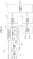
- FIG. 2 is a block diagram illustrating an example of a configuration of the ECU 100 in FIG. 1 .
- the ECU 100 that is the control device for the internal combustion engine of the present embodiment controls a discharge pressure of fuel discharged from the high-pressure fuel pump 5 to the fuel injection device 6 that injects fuel into the combustion chamber of the engine 2.
- the ECU 100 includes, for example, a feedback (FDBK) control unit 110, a flow-rate limiting unit 120, and an energization-start-angle calculation unit 130.
- the ECU 100 includes, for example, an energization-start-angle limiting unit 140, an energization-stop-angle calculation unit 150, an energization-stop-angle limiting unit 160, and an electromagnetic-valve control unit 170.
- Each unit of the ECU 100 illustrated in FIG. 2 represents each function of the control device for the internal combustion engine of the present embodiment, performed by, for example, execution of a program stored in a storage device such as a memory, by a central processing unit (CPU).
- a single unit may include one or a plurality of devices, and a plurality of units may include one device.
- the feedback control unit 110 receives, for example, a detected pressure value Pd provided from the pressure sensor 63 for fuel discharged from the high-pressure fuel pump 5 to the fuel injection device 6, and a target pressure value Pt of a discharge pressure of the high-pressure fuel pump 5.
- the ECU 100 inputs, for example, the target pressure value Pt of the discharge pressure of the high-pressure fuel pump 5 calculated on the basis of a detected value provided from the accelerator opening sensor 7, to the feedback control unit 110.
- the feedback control unit 110 outputs, for example, a pressure deviation ⁇ P between the detected pressure value Pd and the target pressure value Pt and a target flow-rate value QT of a discharge flow-rate of the high-pressure fuel pump 5, on the basis of the detected pressure value Pd and the target pressure value Pt that have been input. More specifically, the feedback control unit 110 calculates the target flow-rate value QT as a required discharge amount of the high-pressure fuel pump 5 necessary for making the detected pressure value Pd equal to the target pressure value Pt.
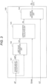
- FIG. 3 is a block diagram illustrating an example of the flow-rate limiting unit 120 of the ECU 100 in FIG. 2 .
- the flow-rate limiting unit 120 receives the pressure deviation ⁇ P and the target flow-rate value QT, and outputs a limited flow-rate value QL corresponding to the target flow-rate value QT having been limited, on the basis of a value and a change amount d ⁇ P of the pressure deviation ⁇ P.
- the flow-rate limiting unit 120 includes, for example, a change-amount calculation unit 121, a limit-value determination unit 122, a limited-flow-rate calculation unit 123, and a limiting processing unit 124.
- FIG. 4 is a flowchart illustrating a flow of processes performed by the energization-start-angle calculation unit 130 in FIG. 3 .
- the flow-rate limiting unit 120 first starts a process S1 of calculating the change amount d ⁇ P of the pressure deviation ⁇ P.
- the change-amount calculation unit 121 calculates the change amount d ⁇ P of the pressure deviation ⁇ P on the basis of, for example, the pressure deviation ⁇ P input from the feedback control unit 110.
- the change amount d ⁇ P of the pressure deviation ⁇ P is an increase or decrease in the pressure deviation ⁇ P per unit time, in other words, a change rate of the pressure deviation ⁇ P. More specifically, for example, the change-amount calculation unit 121 divides a difference between the pressure deviation ⁇ P obtained in a previous process and the pressure deviation ⁇ P obtained in a current process by a process cycle, to calculate the change amount d ⁇ P of the pressure deviation ⁇ P.
- the flow-rate limiting unit 120 performs a process S2 of determining a limit value LV.
- the limit-value determination unit 122 determines, as the limit value LV, a larger value as the value of the pressure deviation ⁇ P decreases and as the change amount d ⁇ P of the pressure deviation ⁇ P increases. More specifically, the limit-value determination unit 122 uses, for example, a limit-value map stored in a storage device such as a memory forming the ECU 100, and determines the limit value LV on the basis of the value and the change amount d ⁇ P of the pressure deviation ⁇ P.
- FIG. 5 is a graph illustrating an example of the limit-value map used in the process S2 of determining the limit value LV in FIG. 4 .
- a limit value LV(H) indicated by a dark-color circle is the limit value LV larger than a limit value LV(L) indicated by a light-color circle.
- the limit-value map is, for example, a graph with a horizontal axis representing the pressure deviation ⁇ P [%] and a vertical axis representing the change amount d ⁇ P [%/s], and the values therein are plotted such that a larger value is selected as the limit value LV(H) as the value of the pressure deviation ⁇ P decreases and as the change amount d ⁇ P of the pressure deviation ⁇ P increases.
- the limit value LV is not set until the detected pressure value Pd reaches 63.2 [%] of the target pressure value Pt, in other words, until the pressure deviation ⁇ P between the target pressure value Pt and the detected pressure value Pd becomes equal to 36.8 [%] or less.
- the limit-value determination unit 122 refers to the above-described limit-value map and determines the limit value LV on the basis of the value of the pressure deviation ⁇ P and the change amount d ⁇ P of the pressure deviation ⁇ P.
- the flow-rate limiting unit 120 performs a process S3 of calculating the limited flow-rate value QL.
- the limited-flow-rate calculation unit 123 subtracts the limit value LV from an upper-limit discharge flow-rate Qmax based on static characteristic of the high-pressure fuel pump 5, to calculate the limited flow-rate value QL.
- the upper-limit discharge flow-rate Qmax based on the static characteristic of the high-pressure fuel pump 5 is input from the energization-start-angle calculation unit 130 to the flow-rate limiting unit 120, for example, as illustrated in FIG. 2 .
- the flow-rate limiting unit 120 performs a flow-rate limiting process S4 of limiting the target flow-rate value QT using the limited flow-rate value QL.
- the limiting processing unit 124 receives the limited flow-rate value QL output from the limited-flow-rate calculation unit 123 and the target flow-rate value QT output from the feedback control unit 110.
- the limiting processing unit 124 outputs the target flow-rate value QT when the target flow-rate value QT does not exceed the limited flow-rate value QL, and outputs the limited flow-rate value QL when the target flow-rate value QT exceeds the limited flow-rate value QL.
- the output of the flow-rate limiting unit 120 is limited to the limited flow-rate value QL obtained by subtraction of the limit value LV from the upper-limit discharge flow-rate Qmax, or less. Then, the process flow of the flow-rate limiting unit 120 illustrated in FIG. 4 ends.
- the energization-start-angle calculation unit 130 receives the number of revolutions Re of the engine 2, a voltage Vb of a battery, and the limited flow-rate value QL or the target flow-rate value QT output from the flow-rate limiting unit 120.
- the energization-start-angle calculation unit 130 calculates, for example, an energization start phase ⁇ on in reciprocation of the plunger 54 that starts energization of the electromagnetic valve 52 of the high-pressure fuel pump 5 in accordance with the limited flow-rate value QL or the target flow-rate value QT having been input.
- the energization-start-angle calculation unit 130 refers to, for example, a static-characteristic map of the high-pressure fuel pump 5 stored in a storage device such as a memory of the ECU 100, and outputs the upper-limit discharge flow-rate Qmax of the high-pressure fuel pump 5, to the flow-rate limiting unit 120. More specifically, the energization-start-angle calculation unit 130 refers to, for example, the static-characteristic map of the high-pressure fuel pump 5 corresponding to the number of revolutions Re of the engine 2 and the voltage Vb of the battery.
- the static-characteristic map of the high-pressure fuel pump 5 is, for example, a graph with a horizontal axis representing an energization start phase ⁇ on [deg] and a vertical axis representing a discharge flow-rate Q [mg/stroke] of the high-pressure fuel pump 5.
- the energization-start-angle calculation unit 130 outputs the energization start phase ⁇ on corresponding to the limited flow-rate value QL or the target flow-rate value QT having been input, on the basis of the static-characteristic map of the high-pressure fuel pump 5.
- the energization-start-angle limiting unit 140 receives the energization start phase ⁇ on output from the energization-start-angle calculation unit 130.
- the energization-start-angle limiting unit 140 outputs an energization start phase ⁇ Lon corresponding to the input energization start phase ⁇ on having been limited using a phase of a bottom dead center (BDC) and a phase of a top dead center (TDC) of the plunger 54.
- BDC bottom dead center
- TDC top dead center
- the energization-stop-angle calculation unit 150 receives, for example, a crank angle ⁇ cra and a cam angle ⁇ cam detected by a crank-angle sensor and a cam-angle sensor that detect rotation angles of the crankshaft and the camshaft of the engine 2.
- the energization-stop-angle calculation unit 150 outputs an energization stop phase ⁇ off of the electromagnetic valve 52 of the high-pressure fuel pump 5 based on the crank angle ⁇ cra and the cam angle ⁇ cam.
- the energization-stop-angle limiting unit 160 receives the energization stop phase ⁇ off output from the energization-stop-angle calculation unit 150.
- the energization-stop-angle limiting unit 160 outputs an energization stop phase ⁇ Loff corresponding to the input energization stop phase ⁇ off having been limited using a phase of a BDC and a phase of a TDC of the plunger 54.
- the electromagnetic-valve control unit 170 generates a drive pulse DP for driving a solenoid of the electromagnetic valve 52 of the high-pressure fuel pump 5 on the basis of the energization start phase ⁇ Lon and the energization stop phase ⁇ Loff that have been input, and outputs the drive pulse DP to the electromagnetic valve 52 of the high-pressure fuel pump 5. More specifically, the electromagnetic-valve control unit 170 receives, for example, a detected phase value ⁇ d provided from an angle sensor that detects a phase of the plunger 54, the energization start phase ⁇ Lon, and the energization stop phase ⁇ Loff.
- the electromagnetic-valve control unit 170 starts energization of the electromagnetic valve 52 and opens the flow path 57. Meanwhile, for example, when the detected phase value ⁇ d matches with the energization stop phase ⁇ Loff, the electromagnetic-valve control unit 170 stops energization of the electromagnetic valve 52 and closes the flow path 57.
- fuel at a flow rate corresponding to the limited flow-rate value QL or the target flow-rate value QT output from the flow-rate limiting unit 120 is supplied to the pressurization chamber 53 of the high-pressure fuel pump 5 and is discharged from the high-pressure fuel pump 5 to the fuel injection device 6.
- FIG. 6 is a graph for describing an operation performed by the control device for the internal combustion engine of the present embodiment illustrated in FIG. 2 .
- the operation of the control device for the internal combustion engine according to the present embodiment will be described on the basis of comparison with a control device for an internal combustion engine according to a comparative example.
- a graph at the upper left of FIG. 6 is a graph illustrating change with time of the target pressure value Pt and the detected pressure value Pd of the high-pressure fuel pump 5 controlled by the control device for the internal combustion engine according to the comparative example.
- a graph at the lower left of FIG. 6 is a graph illustrating change with time of the target flow-rate value QT and a discharge flow-rate Qd actually detected by a flow-rate sensor, for the high-pressure fuel pump 5 controlled by the control device for the internal combustion engine according to the comparative example.
- the control device for the internal combustion engine according to the comparative example is different from the ECU 100 that is the control device for the internal combustion engine according to the present embodiment in that the flow-rate limiting unit 120 illustrated in FIG. 2 is not included.
- the other components of the control device for the internal combustion engine according to the comparative example are similar to those of the control device for the internal combustion engine according to the present embodiment.
- the feedback control unit 110 performs feedback control of the discharge pressure, in other words, the detected pressure value Pd, of the high-pressure fuel pump 5.
- the target pressure value Pt having a stepwise shape as illustrated in the graph at the upper left of FIG. 6 is input to the feedback control unit 110.
- the target flow-rate value QT output from the feedback control unit 110 rapidly increases, and for example, the target flow-rate value QT is limited to the upper-limit discharge flow-rate Qmax by the energization-start-angle calculation unit 130.
- the discharge flow-rate Qd of fuel in the high-pressure fuel pump 5 increases beyond the target flow-rate value QT.
- the control device for the internal combustion engine according to the comparative example there occurs overshoot in which the detected pressure value Pd that is the discharge pressure of the high-pressure fuel pump 5 rapidly increases, to greatly exceed the target pressure value Pt, so that pulsation is generated in the discharge pressure of fuel in the high-pressure fuel pump 5.
- control device for the internal combustion engine according to the comparative example not including the flow-rate limiting unit 120 has a problem of reduction in stability of a transient response of the discharge pressure of fuel in the high-pressure fuel pump 5, to the target pressure value Pt.
- control device for the internal combustion engine of the comparative example when overshoot of the discharge pressure of the high-pressure fuel pump 5 is suppressed by gain adjustment of the feedback control unit 110, there is a possibility of reduction in responsiveness of the discharge pressure of the high-pressure fuel pump 5, to the target pressure value Pt.
- the ECU 100 forming the control device for the internal combustion engine of the present embodiment controls the discharge pressure of fuel discharged from the high-pressure fuel pump 5 to the fuel injection device 6.
- the high-pressure fuel pump 5 includes the pressurization chamber 53 into which fuel is introduced from the fuel tank 3 via the low-pressure fuel pump 4, the electromagnetic valve 52 that opens and closes the flow path 57 through which the fuel is introduced into the pressurization chamber 53, and the plunger 54 that pressurizes the fuel introduced into the pressurization chamber 53.
- the fuel injection device 6 injects the fuel into the combustion chamber of the engine 2 that is an internal combustion engine.
- the ECU 100 includes the feedback control unit 110, the flow-rate limiting unit 120, and the energization-start-angle calculation unit 130 as described above.
- the feedback control unit 110 receives the detected pressure value Pd provided from the pressure sensor 63 for fuel discharged from the high-pressure fuel pump 5 to the fuel injection device 6, and the target pressure value Pt of the discharge pressure of the high-pressure fuel pump 5. Further, the feedback control unit 110 outputs the pressure deviation ⁇ P between the detected pressure value Pd and the target pressure value Pt on the basis of the target pressure value Pt and the detected pressure value Pd that have been input, and the target flow-rate value QT of a discharge flow-rate of the high-pressure fuel pump 5.
- the flow-rate limiting unit 120 receives the pressure deviation ⁇ P and the target flow-rate value QT, and outputs a limited flow-rate value QL corresponding to the target flow-rate value QT having been limited, on the basis of a value and a change amount d ⁇ P of the pressure deviation ⁇ P.
- the energization-start-angle calculation unit 130 calculates the energization start phase ⁇ on in reciprocation of the plunger 54 that starts energization of the electromagnetic valve 52 of the high-pressure fuel pump 5 in accordance with the limited flow-rate value QL.
- the control device for the internal combustion engine of the present embodiment operates as follows when the target pressure value Pt having a stepwise shape as illustrated in a graph at the upper right of FIG. 6 is input to the feedback control unit 110 in the same manner as in the above-described comparative example.
- the target flow-rate value QT output from the feedback control unit 110 rapidly increases, and, for example, the target flow-rate value QT is limited to the upper-limit discharge flow-rate Qmax based on the static characteristic of the high-pressure fuel pump 5 by the energization-start-angle calculation unit 130.
- the detected pressure value Pd provided from the pressure sensor 63 for fuel discharged from the high-pressure fuel pump 5 to the fuel injection device 6 rapidly increases. Then, the pressure deviation ⁇ P between the target pressure value Pt and the detected pressure value Pd decreases, and the change amount d ⁇ P of the detected pressure value Pd increases, for example, until the detected pressure value Pd reaches approximately 62.3 [%] of the target pressure value Pt.
- control device for the internal combustion engine of the present embodiment includes the flow-rate limiting unit 120 that outputs the limited flow-rate value QL corresponding to the target flow-rate value QT having been limited, on the basis of the value and the change amount d ⁇ P of the pressure deviation ⁇ P, as described above.
- the flow-rate limiting unit 120 limits the target flow-rate value QT to a lower limited flow-rate value QL1 before the detected pressure value Pd exceeds the target pressure value Pt.
- the energization-start-angle calculation unit 130 calculates the energization start phase ⁇ on in reciprocation of the plunger 54 that starts energization of the electromagnetic valve 52 of the high-pressure fuel pump 5 in accordance with the limited flow-rate value QL1 output from the flow-rate limiting unit 120. Consequently, an increase in the discharge flow-rate Qd of the high-pressure fuel pump 5 is limited, and the change amount d ⁇ P of the pressure deviation ⁇ P between the detected pressure value Pd of fuel discharged from the high-pressure fuel pump 5 to the fuel injection device 6 and the target pressure value Pt decreases.
- the discharge flow-rate Qd of the high-pressure fuel pump 5 is prevented from exceeding the target flow-rate value QT, thereby preventing overshoot in which the detected pressure value Pd of fuel discharged from the high-pressure fuel pump 5 to the fuel injection device 6 exceeds the target pressure value Pt.
- the flow-rate limiting unit 120 limits the target flow-rate value QT to a limited flow-rate value QL2 that is larger than the limited flow-rate value QL1 and is smaller than the target flow-rate value QT, on the basis of the decreased change amount d ⁇ P of the pressure deviation ⁇ P. Consequently, an excessive decrease in the discharge flow-rate Qd of the high-pressure fuel pump 5 is prevented, resulting in improvement of the responsiveness of the detected pressure value Pd of fuel discharged from the high-pressure fuel pump 5 to the fuel injection device 6, to the target pressure value Pt.
- the flow-rate limiting unit 120 includes the limit-value determination unit 122, the limited-flow-rate calculation unit 123, and the limiting processing unit 124.
- the limit-value determination unit 122 determines, as the limit value LV, a larger value as the value of the pressure deviation ⁇ P decreases and as the change amount d ⁇ P of the pressure deviation ⁇ P increases.
- the limited-flow-rate calculation unit 123 calculates the limited flow-rate value QL by subtracting the limit value LV from the upper-limit discharge flow-rate Qmax based on the static characteristic of the high-pressure fuel pump 5.
- the control device for the internal combustion engine of the present embodiment when the target pressure value Pt having a stepwise shape is input to the feedback control unit 110 as illustrated in the graph at the upper right of FIG. 6 , the detected pressure value Pd that is the discharge pressure of the high-pressure fuel pump 5 rapidly increases. As a result, the pressure deviation ⁇ P between the target pressure value Pt and the detected pressure value Pd decreases, and the change amount d ⁇ P of the pressure deviation ⁇ P increases, so that a relatively-large value is determined as the limit value LV.
- the target flow-rate value QT is limited to the relatively-small limited flow-rate value QL1 that is obtained by subtraction of the relatively-large limit value LV from the upper-limit discharge flow-rate Qmax. Therefore, according to the control device for the internal combustion engine of the present embodiment, it is possible to prevent overshoot in which the detected pressure value Pd exceeds the target pressure value Pt, thereby improving the stability of the transient response of the discharge pressure of the high-pressure fuel pump 5, to the target pressure value Pt.
- the control device for the internal combustion engine of the present embodiment it is possible to prevent an excessive decrease in the discharge flow-rate Qd of the high-pressure fuel pump 5, thereby improving the responsiveness of the transient response of the detected pressure value Pd of fuel discharged from the high-pressure fuel pump 5 to the fuel injection device 6, to the target pressure value Pt.
- control device for the internal combustion engine of the present embodiment further includes the electromagnetic-valve control unit 170 illustrated in FIG. 2 .
- the electromagnetic-valve control unit 170 receives the detected phase value ⁇ d provided from the angle sensor that detects a phase of the plunger 54 of the high-pressure fuel pump 5, and the energization start phase ⁇ Lon.
- the electromagnetic-valve control unit 170 starts energization of the electromagnetic valve 52 and opens the flow path 57 when the detected phase value ⁇ d matches with the energization start phase ⁇ Lon.
- control device for an internal combustion engine that can simultaneously improve stability and responsiveness of a transient response of the discharge pressure of the high-pressure fuel pump 5, to the target pressure value Pt.
- control device for the internal combustion engine of the present embodiment is not limited to the above-described embodiment. Below, some modifications of the foregoing embodiment will be described with reference to FIGS. 7 and 8 .
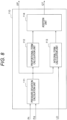
- FIG. 7 is a block diagram illustrating a modification of the flow-rate limiting unit 120 in FIG. 3 .
- the flow-rate limiting unit 120 may omit the limited-flow-rate calculation unit 123 illustrated in FIG. 3 .
- the flow-rate limiting unit 120 includes the change-amount calculation unit 121, the limit-value determination unit 122, and the limiting processing unit 124.
- the change-amount calculation unit 121 receives the pressure deviation ⁇ P and calculates the change amount d ⁇ P of the pressure deviation ⁇ P in the same manner as in the above-described embodiment.
- the limit-value determination unit 122 determines, as the limit value LV, a larger value as the value of the pressure deviation ⁇ P decreases and as the change amount d ⁇ P of the pressure deviation ⁇ P increases in the same manner as in the above-described embodiment. Then, the limiting processing unit 124 calculates the limited flow-rate value QL obtained by subtraction of the limit value LV from the target flow-rate value QT.
- control device for the internal combustion engine according to this modification can also produce the same effects as those of the control device for the internal combustion engine according to the above-described embodiment. Therefore, also in the present modification, it is possible to provide a control device for an internal combustion engine that can simultaneously improve stability and responsiveness of a transient response of the discharge pressure of the high-pressure fuel pump 5, to the target pressure value Pt.
- the flow-rate limiting unit 120 limits a value of the target flow-rate value QT to the limited flow-rate value QL obtained by subtraction of the limit value LV from the upper-limit discharge flow-rate Qmax or the target flow-rate value QT.
- the control device for the internal combustion engine according to the present disclosure can also limit the target flow-rate value QT by other methods.
- the flow-rate limiting unit 120 may include the limit-value determination unit 122 that determines the limit value LV on the basis of the value and the change amount d ⁇ P of the pressure deviation ⁇ P, and the limiting processing unit 124 that outputs the limited flow-rate value QL corresponding to the target flow-rate value QT of which change amount has been limited using the limit value LV.
- the limit value LV is a value for limiting an amount of change in the target flow-rate value QT, i.e., a difference between a previous value and a current value of the target flow-rate value QT.
- the control device for the internal combustion engine according to this modification not only can produce the same effects as those of the control device for the internal combustion engine according to the above-described embodiment, but also is applicable to the high-pressure fuel pump 5 and the fuel injection device 6 having a large individual difference in static characteristics.
- the high-pressure fuel pump 5 and the fuel injection device 6 have each a large individual difference in static characteristic, it is more effective to limit an amount of change in the target flow-rate value QT than to limit the upper value (absolute value) of the target flow-rate value QT output from the feedback control unit 110.
- FIG. 8 is a block diagram illustrating an example of the feedback control unit 110 of the control device for the internal combustion engine in FIG. 2 .
- the feedback control unit 110 includes a pressure-deviation calculation unit 111, a proportional-term calculation unit 112, an integral-term calculation unit 113, and an addition unit 114.
- the pressure-deviation calculation unit 111 calculates the pressure deviation ⁇ P using the target pressure value Pt and the detected pressure value Pd as inputs.
- the proportional-term calculation unit 112 calculates a proportional term on the basis of the pressure deviation ⁇ P.
- the integral-term calculation unit 113 calculates an integral term on the basis of the pressure deviation ⁇ P.
- the addition unit 114 adds the proportional term and the integral term to calculate the target flow-rate value QT.
- the integral-term calculation unit 113 receives a determination of limiting LD from the flow-rate limiting unit 120 as illustrated in FIGS. 2 and 8 .
- the integral-term calculation unit 113 stops calculation of an integral term when the target flow-rate value QT is limited using the limited flow-rate value QL, in other words, when the determination of limiting LD is input.
- the target flow-rate value QT is limited using the limited flow-rate value QL, and calculation of an integral term by the integral-term calculation unit 113 is stopped in the feedback control unit 110, so that overcorrection of the target flow-rate value QT, that is, accumulation of integral quantities, can be prevented. Therefore, it is possible to more effectively prevent the detected pressure value Pd of the discharge pressure of the high-pressure fuel pump 5 from overshooting the target pressure value Pt. Meanwhile, it is possible to stop calculation of an integral term, for example, by holding a calculated value, setting a calculated value to zero, or subtracting an amount of overcorrection at the time of limiting the target flow-rate value QT from a calculated value of an integral term.
Landscapes
- Engineering & Computer Science (AREA)
- Chemical & Material Sciences (AREA)
- Combustion & Propulsion (AREA)
- Mechanical Engineering (AREA)
- General Engineering & Computer Science (AREA)
- Fuel-Injection Apparatus (AREA)
Abstract
Description
- The present disclosure relates to a control device for an internal combustion engine.
- Conventionally, a control device for an internal combustion engine has been known. For example, a control device for an internal combustion engine described in the following
PTL 1 controls an internal combustion engine including an engine-driven high-pressure fuel pump that supplies high-pressure fuel from a fuel tank to a fuel injection means (paragraph 0014 and claim 1). The high-pressure fuel pump is driven by a cam of the internal combustion engine. When an on-off valve on an inlet side of the high-pressure fuel pump is closed at a desired timing based on an angle of a shaft that drives the cam, a desired discharge amount of high-pressure fuel is discharged. - The conventional control device includes a means for detecting the number of revolutions of the internal combustion engine, a means for detecting a pressure of the high-pressure fuel, and a control means for performing feedback control of the high-pressure fuel pump so that the detected pressure of the high-pressure fuel is equal to a target pressure. The control means includes a means for calculating a deviation between the detected pressure of the high-pressure fuel and the target pressure, a means for calculating an amount of feedback operation on the basis of the deviation, and a calculation means for calculating a required discharge amount of the high-pressure fuel pump on the basis of the amount of feedback operation.
- Further, the control means includes a means for calculating an angle of the shaft satisfying the required discharge amount in consideration of the number of revolutions of the internal combustion engine and the detected pressure of the high-pressure fuel, and a means for controlling the on-off valve such that the on-off valve is closed when an angle of the shaft becomes equal to the calculated angle. The above-described control device further includes a means for detecting a sudden change in the target pressure, and a holding means for holding a parameter of the feedback control such that the parameter is not changed when the sudden change is detected.
- When the target pressure of the high-pressure fuel is suddenly changed, the conventional control device for the internal combustion engine holds an integral term that is a parameter of the feedback control without updating it. In this manner, it is possible to prevent a large integral term from being calculated due to integration of a large integral term while the deviation is large, and hence, considerable overshoot or considerable undershoot can be avoided (
PTL 1, paragraph 0015). - PTL 1:
JP 2007-032322 A - In the above-described conventional control device for the internal combustion engine, the integral term of the feedback control is held without being updated, so that a discharge pressure of the high-pressure fuel pump can be prevented from considerably overshooting the target pressure value. However, in the conventional control device for the internal combustion engine, there is a possibility of reduction of responsiveness of the discharge pressure of the high-pressure fuel pump, to the target pressure value.
- The present disclosure provides a control device for an internal combustion engine that can simultaneously improve stability and responsiveness of a transient response of a discharge pressure of a high-pressure fuel pump, to a target pressure value.
- One aspect of the present disclosure is directed to a control device for an internal combustion engine, for controlling a discharge pressure of fuel discharged from a high-pressure fuel pump to a fuel injection device that injects the fuel to a combustion chamber of the internal combustion engine, the high-pressure fuel pump including a pressurization chamber into which the fuel is introduced from a fuel tank via a low-pressure fuel pump, an electromagnetic valve that opens and closes a flow path through which the fuel is introduced into the pressurization chamber, and a plunger that pressurizes the fuel introduced into the pressurization chamber, the control device including: a feedback control unit configured to receive a detected pressure value provided from a pressure sensor for the fuel discharged from the high-pressure fuel pump to the fuel injection device, and a target pressure value of the discharge pressure, and configured to output a pressure deviation between the detected pressure value and the target pressure value, and a target flow-rate value of a discharge flow-rate of the high-pressure fuel pump; a flow-rate limiting unit configured to receive the pressure deviation and the target flow-rate value and output a limited flow-rate value corresponding to the target flow-rate value having been limited, on the basis of a value and a change amount of the pressure deviation; and an energization-start-angle calculation unit configured to calculate an energization start phase in reciprocation of the plunger that starts energization of the electromagnetic valve of the high-pressure fuel pump in accordance with the limited flow-rate value.
- According to the above-described aspect of the present disclosure, it is possible to provide a control device for an internal combustion engine that can simultaneously improve stability and responsiveness of a transient response of a discharge pressure of a high-pressure fuel pump, to a target pressure value.
-
- [
FIG. 1] FIG. 1 is a block diagram illustrating an embodiment of a control device for an internal combustion engine according to the present disclosure. - [
FIG. 2] FIG. 2 is a block diagram illustrating an example of a configuration of the control device for the internal combustion engine inFIG. 1 . - [
FIG. 3] FIG. 3 is a block diagram illustrating an example of a flow-rate limiting unit of the control device for the internal combustion engine inFIG. 2 . - [
FIG. 4] FIG. 4 is a flowchart illustrating a flow of processes performed by the flow-rate limiting unit inFIG. 3 . - [
FIG. 5] FIG. 5 is a limit-value map for describing an example of a process of determining a limit value inFIG. 4 . - [
FIG. 6] FIG. 6 is a graph for describing an operation performed by the control device for the internal combustion engine illustrated inFIG. 2 . - [
FIG. 7] FIG. 7 is a block diagram illustrating a modification of the flow-rate limiting unit inFIG. 3 . - [
FIG. 8] FIG. 8 is a block diagram illustrating an example of a FDBK control unit of the control device for the internal combustion engine inFIG. 2 . - Hereinafter, an embodiment of a control device for an internal combustion engine according to the present disclosure will be described with reference to the drawings.
-
FIG. 1 is a block diagram illustrating an embodiment of a control device for an internal combustion engine according to the present disclosure. The control device for the internal combustion engine of the present embodiment includes, for example, an electronic control unit (ECU) 100 that is a part of anengine system 1 mounted on a vehicle. Theengine system 1 includes, for example, anengine 2 that is an internal combustion engine, afuel tank 3, a low-pressure fuel pump 4, a high-pressure fuel pump 5, afuel injection device 6, anaccelerator opening sensor 7, and theECU 100. - The
engine 2 includes, for example, an intake pipe, a throttle body, a throttle valve, an intake manifold, an intake port, a cylinder, a spark plug, a piston, a crankshaft, a camshaft, an exhaust port, an exhaust pipe, and the like that are not illustrated. Theengine 2 takes in intake air to the intake pipe in accordance with, for example, an operation of the piston. A flow rate of the intake air taken in to the intake pipe is controlled by the throttle valve provided in the throttle body while the intake air is passing through the throttle body. - The intake air that has passed through the throttle body passes through the intake manifold, is further mixed with fuel injected from an
injector 62 provided in the intake port, and is guided to a combustion chamber of the cylinder in a state of air-fuel mixture. The spark plug explosively burns the air-fuel mixture in the combustion chamber by spark ignition, to generate mechanical energy, and rotates the crankshaft and the camshaft connected to the piston. The gas generated by the burning is discharged from the combustion chamber of the cylinder to the exhaust pipe via the exhaust port, and is discharged as exhaust gas through the exhaust pipe to the outside of the vehicle. - In the
fuel tank 3, for example, liquid fuel such as gasoline, light oil, and ethanol is stored. The low-pressure fuel pump 4 is provided, for example, in the middle of afuel supply pipe 8 connecting thefuel tank 3 and the high-pressure fuel pump 5, and pumps fuel from thefuel tank 3 to the high-pressure fuel pump 5 through thefuel supply pipe 8. For example, the high-pressure fuel pump 5 pressurizes fuel supplied through thefuel supply pipe 8 and discharges the fuel to acommon rail 61 of thefuel injection device 6. - Meanwhile, a discharge pressure of fuel in low-
pressure fuel pump 4 is lower than a discharge pressure of fuel in the high-pressure fuel pump 5, and a discharge pressure of fuel in the high-pressure fuel pump 5 is higher than a discharge pressure of fuel in the low-pressure fuel pump 4. That is, "low pressure" and "high pressure" regarding the low-pressure fuel pump 4 and the high-pressure fuel pump 5 represent a relative relationship between discharge pressures of the respective fuel pumps, and do not define a specific pressure range. - The high-
pressure fuel pump 5 includes, for example, asuction port 51, anelectromagnetic valve 52, apressurization chamber 53, aplunger 54, adischarge valve 55, and adischarge port 56. Thesuction port 51 is connected to, for example, thefuel supply pipe 8, and fuel pumped by the low-pressure fuel pump 4 is introduced thereinto. Theelectromagnetic valve 52 is provided, for example, in the middle of aflow path 57 for supplying fuel from thesuction port 51 to thepressurization chamber 53, and is opened or closed under the control of theECU 100, to open and close theflow path 57 for supplying fuel to thepressurization chamber 53. - To the
pressurization chamber 53, fuel is introduced from thefuel tank 3 via the low-pressure fuel pump 4. More specifically, fuel is introduced from thefuel tank 3 to thesuction port 51 via the low-pressure fuel pump 4, further passes through theflow path 57 between thesuction port 51 and thepressurization chamber 53 and through theelectromagnetic valve 52 that opens and closes theflow path 57, and is introduced into thepressurization chamber 53. The high-pressure fuel pump 5 may include, for example, apulsation reduction unit 58 that reduces pulsation of a pressure of fuel that is sucked through thesuction port 51 and is discharged through thedischarge port 56. - The
plunger 54 pressurizes fuel introduced into thepressurization chamber 53. Theplunger 54 is housed in, for example, acylinder 59, and defines thepressurization chamber 53, together with thecylinder 59. Theplunger 54 is provided so that it can be axially reciprocated by a drive mechanism (not illustrated). The drive mechanism causes theplunger 54 to axially reciprocate by, for example, rotation of a cam attached to the camshaft of theengine 2. - A phase of reciprocation of the
plunger 54 is detected by, for example, a cam angle sensor that detects a rotation angle of the camshaft, and is input to theECU 100. That is, the cam angle sensor functions as an angle sensor that detects, for example, a phase of theplunger 54 of the high-pressure fuel pump 5, and a detected phase value θd of reciprocation of theplunger 54 can be calculated on the basis of a cam angle λcam detected by the cam angle sensor. - The
discharge valve 55 is provided between thepressurization chamber 53 and thedischarge port 56. While there is no pressure difference between fuel in thepressurization chamber 53 and fuel on a downstream side of thedischarge valve 55, a valve body of thedischarge valve 55 comes into contact with a seat surface of a seat member by a biasing force of a spring, so that the valve is closed. When a pressure of fuel in thepressurization chamber 53 becomes higher than a pressure of fuel on the downstream side of thedischarge valve 55 and the pressure difference therebetween exceeds the biasing force of the spring, the valve body is separated from the seat surface of the seat member and the valve is opened. Thedischarge port 56 is connected to, for example, thecommon rail 61 of thefuel injection device 6, and discharges high-pressure fuel pressurized in thepressurization chamber 53, to thecommon rail 61. - The
fuel injection device 6 includes, for example, thecommon rail 61, theinjector 62, and apressure sensor 63. Thecommon rail 61 stores therein high-pressure fuel supplied from the high-pressure fuel pump 5, and distributes the high-pressure fuel to the plurality ofinjectors 62. Eachinjector 62 injects, for example, high-pressure fuel supplied via thecommon rail 61 into the cylinder of theengine 2. Thepressure sensor 63 detects a pressure of high-pressure fuel discharged from the high-pressure fuel pump 5 to thecommon rail 61, and outputs a result of detection of the pressure, to theECU 100 via a signal line. - The
accelerator opening sensor 7 is connected to, for example, theECU 100 via a signal line, detects an amount of stepping on an accelerator pedal by a driver of the vehicle, as an accelerator opening, and outputs the detected accelerator opening to theECU 100. TheECU 100 includes, for example, one or more microcontrollers, is connected to the low-pressure fuel pump 4, the high-pressure fuel pump 5, and thefuel injection device 6 via signal lines, and controls the low-pressure fuel pump 4, the high-pressure fuel pump 5, and thefuel injection device 6. -
FIG. 2 is a block diagram illustrating an example of a configuration of theECU 100 inFIG. 1 . TheECU 100 that is the control device for the internal combustion engine of the present embodiment controls a discharge pressure of fuel discharged from the high-pressure fuel pump 5 to thefuel injection device 6 that injects fuel into the combustion chamber of theengine 2. TheECU 100 includes, for example, a feedback (FDBK)control unit 110, a flow-rate limiting unit 120, and an energization-start-angle calculation unit 130. Further, theECU 100 includes, for example, an energization-start-angle limiting unit 140, an energization-stop-angle calculation unit 150, an energization-stop-angle limiting unit 160, and an electromagnetic-valve control unit 170. - Each unit of the
ECU 100 illustrated inFIG. 2 represents each function of the control device for the internal combustion engine of the present embodiment, performed by, for example, execution of a program stored in a storage device such as a memory, by a central processing unit (CPU). Note that, regarding each unit of theECU 100 illustrated inFIG. 2 , for example, a single unit may include one or a plurality of devices, and a plurality of units may include one device. - The
feedback control unit 110 receives, for example, a detected pressure value Pd provided from thepressure sensor 63 for fuel discharged from the high-pressure fuel pump 5 to thefuel injection device 6, and a target pressure value Pt of a discharge pressure of the high-pressure fuel pump 5. TheECU 100 inputs, for example, the target pressure value Pt of the discharge pressure of the high-pressure fuel pump 5 calculated on the basis of a detected value provided from theaccelerator opening sensor 7, to thefeedback control unit 110. - The
feedback control unit 110 outputs, for example, a pressure deviation ΔP between the detected pressure value Pd and the target pressure value Pt and a target flow-rate value QT of a discharge flow-rate of the high-pressure fuel pump 5, on the basis of the detected pressure value Pd and the target pressure value Pt that have been input. More specifically, thefeedback control unit 110 calculates the target flow-rate value QT as a required discharge amount of the high-pressure fuel pump 5 necessary for making the detected pressure value Pd equal to the target pressure value Pt. -
FIG. 3 is a block diagram illustrating an example of the flow-rate limiting unit 120 of theECU 100 inFIG. 2 . The flow-rate limiting unit 120 receives the pressure deviation ΔP and the target flow-rate value QT, and outputs a limited flow-rate value QL corresponding to the target flow-rate value QT having been limited, on the basis of a value and a change amount dΔP of the pressure deviation ΔP. The flow-rate limiting unit 120 includes, for example, a change-amount calculation unit 121, a limit-value determination unit 122, a limited-flow-rate calculation unit 123, and a limitingprocessing unit 124. -
FIG. 4 is a flowchart illustrating a flow of processes performed by the energization-start-angle calculation unit 130 inFIG. 3 . After starting the process flow illustrated inFIG. 4 , the flow-rate limiting unit 120 first starts a process S1 of calculating the change amount dΔP of the pressure deviation ΔP. In this process S1, the change-amount calculation unit 121 calculates the change amount dΔP of the pressure deviation ΔP on the basis of, for example, the pressure deviation ΔP input from thefeedback control unit 110. - Here, the change amount dΔP of the pressure deviation ΔP is an increase or decrease in the pressure deviation ΔP per unit time, in other words, a change rate of the pressure deviation ΔP. More specifically, for example, the change-
amount calculation unit 121 divides a difference between the pressure deviation ΔP obtained in a previous process and the pressure deviation ΔP obtained in a current process by a process cycle, to calculate the change amount dΔP of the pressure deviation ΔP. - Subsequently, the flow-
rate limiting unit 120 performs a process S2 of determining a limit value LV. In this process S2, the limit-value determination unit 122 determines, as the limit value LV, a larger value as the value of the pressure deviation ΔP decreases and as the change amount dΔP of the pressure deviation ΔP increases. More specifically, the limit-value determination unit 122 uses, for example, a limit-value map stored in a storage device such as a memory forming theECU 100, and determines the limit value LV on the basis of the value and the change amount dΔP of the pressure deviation ΔP. -
FIG. 5 is a graph illustrating an example of the limit-value map used in the process S2 of determining the limit value LV inFIG. 4 . InFIG. 5 , a limit value LV(H) indicated by a dark-color circle is the limit value LV larger than a limit value LV(L) indicated by a light-color circle. The limit-value map is, for example, a graph with a horizontal axis representing the pressure deviation ΔP [%] and a vertical axis representing the change amount dΔP [%/s], and the values therein are plotted such that a larger value is selected as the limit value LV(H) as the value of the pressure deviation ΔP decreases and as the change amount dΔP of the pressure deviation ΔP increases. - In the example illustrated in
FIG. 5 , two different limit values LV of the relatively-large limit value LV(H) and the relatively-small limit value LV(L) are determined, but three or more different limit values LV may be determined. Further, in the example illustrated inFIG. 5 , the limit value LV is not set until the detected pressure value Pd reaches 63.2 [%] of the target pressure value Pt, in other words, until the pressure deviation ΔP between the target pressure value Pt and the detected pressure value Pd becomes equal to 36.8 [%] or less. The limit-value determination unit 122 refers to the above-described limit-value map and determines the limit value LV on the basis of the value of the pressure deviation ΔP and the change amount dΔP of the pressure deviation ΔP. - Subsequently, the flow-
rate limiting unit 120 performs a process S3 of calculating the limited flow-rate value QL. In this process S3, for example, the limited-flow-rate calculation unit 123 subtracts the limit value LV from an upper-limit discharge flow-rate Qmax based on static characteristic of the high-pressure fuel pump 5, to calculate the limited flow-rate value QL. The upper-limit discharge flow-rate Qmax based on the static characteristic of the high-pressure fuel pump 5 is input from the energization-start-angle calculation unit 130 to the flow-rate limiting unit 120, for example, as illustrated inFIG. 2 . - Subsequently, the flow-
rate limiting unit 120 performs a flow-rate limiting process S4 of limiting the target flow-rate value QT using the limited flow-rate value QL. In this process S4, as illustrated inFIG. 3 , the limitingprocessing unit 124 receives the limited flow-rate value QL output from the limited-flow-rate calculation unit 123 and the target flow-rate value QT output from thefeedback control unit 110. For example, the limitingprocessing unit 124 outputs the target flow-rate value QT when the target flow-rate value QT does not exceed the limited flow-rate value QL, and outputs the limited flow-rate value QL when the target flow-rate value QT exceeds the limited flow-rate value QL. - As a result, the output of the flow-
rate limiting unit 120 is limited to the limited flow-rate value QL obtained by subtraction of the limit value LV from the upper-limit discharge flow-rate Qmax, or less. Then, the process flow of the flow-rate limiting unit 120 illustrated inFIG. 4 ends. - For example, as illustrated in
FIG. 2 , the energization-start-angle calculation unit 130 receives the number of revolutions Re of theengine 2, a voltage Vb of a battery, and the limited flow-rate value QL or the target flow-rate value QT output from the flow-rate limiting unit 120. The energization-start-angle calculation unit 130 calculates, for example, an energization start phase θon in reciprocation of theplunger 54 that starts energization of theelectromagnetic valve 52 of the high-pressure fuel pump 5 in accordance with the limited flow-rate value QL or the target flow-rate value QT having been input. - Further, the energization-start-
angle calculation unit 130 refers to, for example, a static-characteristic map of the high-pressure fuel pump 5 stored in a storage device such as a memory of theECU 100, and outputs the upper-limit discharge flow-rate Qmax of the high-pressure fuel pump 5, to the flow-rate limiting unit 120. More specifically, the energization-start-angle calculation unit 130 refers to, for example, the static-characteristic map of the high-pressure fuel pump 5 corresponding to the number of revolutions Re of theengine 2 and the voltage Vb of the battery. - The static-characteristic map of the high-
pressure fuel pump 5 is, for example, a graph with a horizontal axis representing an energization start phase θon [deg] and a vertical axis representing a discharge flow-rate Q [mg/stroke] of the high-pressure fuel pump 5. For example, the energization-start-angle calculation unit 130 outputs the energization start phase θon corresponding to the limited flow-rate value QL or the target flow-rate value QT having been input, on the basis of the static-characteristic map of the high-pressure fuel pump 5. - The energization-start-
angle limiting unit 140 receives the energization start phase θon output from the energization-start-angle calculation unit 130. The energization-start-angle limiting unit 140 outputs an energization start phase θLon corresponding to the input energization start phase θon having been limited using a phase of a bottom dead center (BDC) and a phase of a top dead center (TDC) of theplunger 54. - The energization-stop-
angle calculation unit 150 receives, for example, a crank angle φcra and a cam angle λcam detected by a crank-angle sensor and a cam-angle sensor that detect rotation angles of the crankshaft and the camshaft of theengine 2. The energization-stop-angle calculation unit 150 outputs an energization stop phase θoff of theelectromagnetic valve 52 of the high-pressure fuel pump 5 based on the crank angle φcra and the cam angle λcam. - The energization-stop-
angle limiting unit 160 receives the energization stop phase θoff output from the energization-stop-angle calculation unit 150. The energization-stop-angle limiting unit 160 outputs an energization stop phase θLoff corresponding to the input energization stop phase θoff having been limited using a phase of a BDC and a phase of a TDC of theplunger 54. - The electromagnetic-
valve control unit 170 generates a drive pulse DP for driving a solenoid of theelectromagnetic valve 52 of the high-pressure fuel pump 5 on the basis of the energization start phase θLon and the energization stop phase θLoff that have been input, and outputs the drive pulse DP to theelectromagnetic valve 52 of the high-pressure fuel pump 5. More specifically, the electromagnetic-valve control unit 170 receives, for example, a detected phase value θd provided from an angle sensor that detects a phase of theplunger 54, the energization start phase θLon, and the energization stop phase θLoff. - For example, when the detected phase value θd matches with the energization start phase θLon, the electromagnetic-
valve control unit 170 starts energization of theelectromagnetic valve 52 and opens theflow path 57. Meanwhile, for example, when the detected phase value θd matches with the energization stop phase θLoff, the electromagnetic-valve control unit 170 stops energization of theelectromagnetic valve 52 and closes theflow path 57. As a result, fuel at a flow rate corresponding to the limited flow-rate value QL or the target flow-rate value QT output from the flow-rate limiting unit 120 is supplied to thepressurization chamber 53 of the high-pressure fuel pump 5 and is discharged from the high-pressure fuel pump 5 to thefuel injection device 6. -
FIG. 6 is a graph for describing an operation performed by the control device for the internal combustion engine of the present embodiment illustrated inFIG. 2 . Below, the operation of the control device for the internal combustion engine according to the present embodiment will be described on the basis of comparison with a control device for an internal combustion engine according to a comparative example. - A graph at the upper left of
FIG. 6 is a graph illustrating change with time of the target pressure value Pt and the detected pressure value Pd of the high-pressure fuel pump 5 controlled by the control device for the internal combustion engine according to the comparative example. A graph at the lower left ofFIG. 6 is a graph illustrating change with time of the target flow-rate value QT and a discharge flow-rate Qd actually detected by a flow-rate sensor, for the high-pressure fuel pump 5 controlled by the control device for the internal combustion engine according to the comparative example. - The control device for the internal combustion engine according to the comparative example is different from the
ECU 100 that is the control device for the internal combustion engine according to the present embodiment in that the flow-rate limiting unit 120 illustrated inFIG. 2 is not included. The other components of the control device for the internal combustion engine according to the comparative example are similar to those of the control device for the internal combustion engine according to the present embodiment. In the control device for the internal combustion engine according to the comparative example, thefeedback control unit 110 performs feedback control of the discharge pressure, in other words, the detected pressure value Pd, of the high-pressure fuel pump 5. - For example, suppose a case in which an accelerator opening that is a detected value provided from the
accelerator opening sensor 7 rapidly increases when the vehicle on which theengine system 1 is mounted suddenly starts. In this case, in the control device for the internal combustion engine of the comparative example, the target pressure value Pt having a stepwise shape as illustrated in the graph at the upper left ofFIG. 6 is input to thefeedback control unit 110. As a result, as illustrated in the graph at the lower left ofFIG. 6 , the target flow-rate value QT output from thefeedback control unit 110 rapidly increases, and for example, the target flow-rate value QT is limited to the upper-limit discharge flow-rate Qmax by the energization-start-angle calculation unit 130. - However, in the control device for the internal combustion engine according to the comparative example not including the flow-
rate limiting unit 120, the discharge flow-rate Qd of fuel in the high-pressure fuel pump 5 increases beyond the target flow-rate value QT. As a result, in the control device for the internal combustion engine according to the comparative example, there occurs overshoot in which the detected pressure value Pd that is the discharge pressure of the high-pressure fuel pump 5 rapidly increases, to greatly exceed the target pressure value Pt, so that pulsation is generated in the discharge pressure of fuel in the high-pressure fuel pump 5. - That is, the control device for the internal combustion engine according to the comparative example not including the flow-
rate limiting unit 120 has a problem of reduction in stability of a transient response of the discharge pressure of fuel in the high-pressure fuel pump 5, to the target pressure value Pt. In the above-described control device for the internal combustion engine of the comparative example, when overshoot of the discharge pressure of the high-pressure fuel pump 5 is suppressed by gain adjustment of thefeedback control unit 110, there is a possibility of reduction in responsiveness of the discharge pressure of the high-pressure fuel pump 5, to the target pressure value Pt. - In contrast thereto, the
ECU 100 forming the control device for the internal combustion engine of the present embodiment controls the discharge pressure of fuel discharged from the high-pressure fuel pump 5 to thefuel injection device 6. As described above, the high-pressure fuel pump 5 includes thepressurization chamber 53 into which fuel is introduced from thefuel tank 3 via the low-pressure fuel pump 4, theelectromagnetic valve 52 that opens and closes theflow path 57 through which the fuel is introduced into thepressurization chamber 53, and theplunger 54 that pressurizes the fuel introduced into thepressurization chamber 53. As described above, thefuel injection device 6 injects the fuel into the combustion chamber of theengine 2 that is an internal combustion engine. TheECU 100 includes thefeedback control unit 110, the flow-rate limiting unit 120, and the energization-start-angle calculation unit 130 as described above. Thefeedback control unit 110 receives the detected pressure value Pd provided from thepressure sensor 63 for fuel discharged from the high-pressure fuel pump 5 to thefuel injection device 6, and the target pressure value Pt of the discharge pressure of the high-pressure fuel pump 5. Further, thefeedback control unit 110 outputs the pressure deviation ΔP between the detected pressure value Pd and the target pressure value Pt on the basis of the target pressure value Pt and the detected pressure value Pd that have been input, and the target flow-rate value QT of a discharge flow-rate of the high-pressure fuel pump 5. The flow-rate limiting unit 120 receives the pressure deviation ΔP and the target flow-rate value QT, and outputs a limited flow-rate value QL corresponding to the target flow-rate value QT having been limited, on the basis of a value and a change amount dΔP of the pressure deviation ΔP. The energization-start-angle calculation unit 130 calculates the energization start phase θon in reciprocation of theplunger 54 that starts energization of theelectromagnetic valve 52 of the high-pressure fuel pump 5 in accordance with the limited flow-rate value QL. - With the above-described configuration, the control device for the internal combustion engine of the present embodiment operates as follows when the target pressure value Pt having a stepwise shape as illustrated in a graph at the upper right of
FIG. 6 is input to thefeedback control unit 110 in the same manner as in the above-described comparative example. As illustrated in a graph at the lower right ofFIG. 6 , the target flow-rate value QT output from thefeedback control unit 110 rapidly increases, and, for example, the target flow-rate value QT is limited to the upper-limit discharge flow-rate Qmax based on the static characteristic of the high-pressure fuel pump 5 by the energization-start-angle calculation unit 130. - Further, because of the rapid increase of the target flow-rate value QT of the discharge flow-rate of the high-
pressure fuel pump 5, the detected pressure value Pd provided from thepressure sensor 63 for fuel discharged from the high-pressure fuel pump 5 to thefuel injection device 6 rapidly increases. Then, the pressure deviation ΔP between the target pressure value Pt and the detected pressure value Pd decreases, and the change amount dΔP of the detected pressure value Pd increases, for example, until the detected pressure value Pd reaches approximately 62.3 [%] of the target pressure value Pt. - Note that the control device for the internal combustion engine of the present embodiment includes the flow-
rate limiting unit 120 that outputs the limited flow-rate value QL corresponding to the target flow-rate value QT having been limited, on the basis of the value and the change amount dΔP of the pressure deviation ΔP, as described above. Thus, as illustrated in the graphs at the upper right and the lower right ofFIG. 6 , the flow-rate limiting unit 120 limits the target flow-rate value QT to a lower limited flow-rate value QL1 before the detected pressure value Pd exceeds the target pressure value Pt. - As a result, the energization-start-
angle calculation unit 130 calculates the energization start phase θon in reciprocation of theplunger 54 that starts energization of theelectromagnetic valve 52 of the high-pressure fuel pump 5 in accordance with the limited flow-rate value QL1 output from the flow-rate limiting unit 120. Consequently, an increase in the discharge flow-rate Qd of the high-pressure fuel pump 5 is limited, and the change amount dΔP of the pressure deviation ΔP between the detected pressure value Pd of fuel discharged from the high-pressure fuel pump 5 to thefuel injection device 6 and the target pressure value Pt decreases. As a result, the discharge flow-rate Qd of the high-pressure fuel pump 5 is prevented from exceeding the target flow-rate value QT, thereby preventing overshoot in which the detected pressure value Pd of fuel discharged from the high-pressure fuel pump 5 to thefuel injection device 6 exceeds the target pressure value Pt. - Further, the flow-
rate limiting unit 120 limits the target flow-rate value QT to a limited flow-rate value QL2 that is larger than the limited flow-rate value QL1 and is smaller than the target flow-rate value QT, on the basis of the decreased change amount dΔP of the pressure deviation ΔP. Consequently, an excessive decrease in the discharge flow-rate Qd of the high-pressure fuel pump 5 is prevented, resulting in improvement of the responsiveness of the detected pressure value Pd of fuel discharged from the high-pressure fuel pump 5 to thefuel injection device 6, to the target pressure value Pt. - More specifically, in the control device for the internal combustion engine of the present embodiment, the flow-
rate limiting unit 120 includes the limit-value determination unit 122, the limited-flow-rate calculation unit 123, and the limitingprocessing unit 124. The limit-value determination unit 122 determines, as the limit value LV, a larger value as the value of the pressure deviation ΔP decreases and as the change amount dΔP of the pressure deviation ΔP increases. The limited-flow-rate calculation unit 123 calculates the limited flow-rate value QL by subtracting the limit value LV from the upper-limit discharge flow-rate Qmax based on the static characteristic of the high-pressure fuel pump 5. The limitingprocessing unit 124 outputs the target flow-rate value QT when the target flow-rate value QT does not exceed the limited flow-rate value QL, and outputs the limited flow-rate value QL when the target flow-rate value QT exceeds the limited flow-rate value QL. - With the above-described configuration, in the control device for the internal combustion engine of the present embodiment, when the target pressure value Pt having a stepwise shape is input to the
feedback control unit 110 as illustrated in the graph at the upper right ofFIG. 6 , the detected pressure value Pd that is the discharge pressure of the high-pressure fuel pump 5 rapidly increases. As a result, the pressure deviation ΔP between the target pressure value Pt and the detected pressure value Pd decreases, and the change amount dΔP of the pressure deviation ΔP increases, so that a relatively-large value is determined as the limit value LV. - Consequently, the target flow-rate value QT is limited to the relatively-small limited flow-rate value QL1 that is obtained by subtraction of the relatively-large limit value LV from the upper-limit discharge flow-rate Qmax. Therefore, according to the control device for the internal combustion engine of the present embodiment, it is possible to prevent overshoot in which the detected pressure value Pd exceeds the target pressure value Pt, thereby improving the stability of the transient response of the discharge pressure of the high-
pressure fuel pump 5, to the target pressure value Pt. - After that, the change amount dΔP of the pressure deviation ΔP decreases, so that the limit value LV that is relatively small is determined. Consequently, the target flow-rate value QT is limited to the relatively-large limited flow-rate value QL2 that is obtained by subtraction of the relatively-small limit value LV from the upper-limit discharge flow-rate Qmax as illustrated in the graph at the lower right of
FIG. 6 . Therefore, according to the control device for the internal combustion engine of the present embodiment, it is possible to prevent an excessive decrease in the discharge flow-rate Qd of the high-pressure fuel pump 5, thereby improving the responsiveness of the transient response of the detected pressure value Pd of fuel discharged from the high-pressure fuel pump 5 to thefuel injection device 6, to the target pressure value Pt. - Moreover, the control device for the internal combustion engine of the present embodiment further includes the electromagnetic-
valve control unit 170 illustrated inFIG. 2 . The electromagnetic-valve control unit 170 receives the detected phase value θd provided from the angle sensor that detects a phase of theplunger 54 of the high-pressure fuel pump 5, and the energization start phase θLon. The electromagnetic-valve control unit 170 starts energization of theelectromagnetic valve 52 and opens theflow path 57 when the detected phase value θd matches with the energization start phase θLon. - With this configuration, when a phase of reciprocation of the
plunger 54 matches with the energization start phase θLon, energization of the solenoid of theelectromagnetic valve 52 of the high-pressure fuel pump 5 is started, so that theflow path 57 is opened. As a result, fuel is introduced from thefuel tank 3 to thepressurization chamber 53 of the high-pressure fuel pump 5 via the low-pressure fuel pump 4, and is pressurized in thepressurization chamber 53 of the high-pressure fuel pump 5, and fuel at a flow rate corresponding to the limited flow-rate value QL or the target flow-rate value QT is discharged from the high-pressure fuel pump 5 to thefuel injection device 6. - As described above, according to the present embodiment, it is possible to provide a control device for an internal combustion engine that can simultaneously improve stability and responsiveness of a transient response of the discharge pressure of the high-
pressure fuel pump 5, to the target pressure value Pt. Note that the control device for the internal combustion engine of the present embodiment is not limited to the above-described embodiment. Below, some modifications of the foregoing embodiment will be described with reference toFIGS. 7 and8 . -
FIG. 7 is a block diagram illustrating a modification of the flow-rate limiting unit 120 inFIG. 3 . For example, the flow-rate limiting unit 120 may omit the limited-flow-rate calculation unit 123 illustrated inFIG. 3 . In the modification of the control device for the internal combustion engine illustrated inFIG. 7 , the flow-rate limiting unit 120 includes the change-amount calculation unit 121, the limit-value determination unit 122, and the limitingprocessing unit 124. The change-amount calculation unit 121 receives the pressure deviation ΔP and calculates the change amount dΔP of the pressure deviation ΔP in the same manner as in the above-described embodiment. The limit-value determination unit 122 determines, as the limit value LV, a larger value as the value of the pressure deviation ΔP decreases and as the change amount dΔP of the pressure deviation ΔP increases in the same manner as in the above-described embodiment. Then, the limitingprocessing unit 124 calculates the limited flow-rate value QL obtained by subtraction of the limit value LV from the target flow-rate value QT. - The control device for the internal combustion engine according to this modification can also produce the same effects as those of the control device for the internal combustion engine according to the above-described embodiment. Therefore, also in the present modification, it is possible to provide a control device for an internal combustion engine that can simultaneously improve stability and responsiveness of a transient response of the discharge pressure of the high-
pressure fuel pump 5, to the target pressure value Pt. - Meanwhile, in the control device for the internal combustion engine according to the above-described embodiment and modification, the flow-
rate limiting unit 120 limits a value of the target flow-rate value QT to the limited flow-rate value QL obtained by subtraction of the limit value LV from the upper-limit discharge flow-rate Qmax or the target flow-rate value QT. However, the control device for the internal combustion engine according to the present disclosure can also limit the target flow-rate value QT by other methods. - For example, in the example illustrated in
FIG. 7 , the flow-rate limiting unit 120 may include the limit-value determination unit 122 that determines the limit value LV on the basis of the value and the change amount dΔP of the pressure deviation ΔP, and the limitingprocessing unit 124 that outputs the limited flow-rate value QL corresponding to the target flow-rate value QT of which change amount has been limited using the limit value LV. That is, the limit value LV is a value for limiting an amount of change in the target flow-rate value QT, i.e., a difference between a previous value and a current value of the target flow-rate value QT. - The control device for the internal combustion engine according to this modification not only can produce the same effects as those of the control device for the internal combustion engine according to the above-described embodiment, but also is applicable to the high-
pressure fuel pump 5 and thefuel injection device 6 having a large individual difference in static characteristics. In other words, in a case in which the high-pressure fuel pump 5 and thefuel injection device 6 have each a large individual difference in static characteristic, it is more effective to limit an amount of change in the target flow-rate value QT than to limit the upper value (absolute value) of the target flow-rate value QT output from thefeedback control unit 110. -
FIG. 8 is a block diagram illustrating an example of thefeedback control unit 110 of the control device for the internal combustion engine inFIG. 2 . In the example illustrated inFIG. 8 , thefeedback control unit 110 includes a pressure-deviation calculation unit 111, a proportional-term calculation unit 112, an integral-term calculation unit 113, and anaddition unit 114. The pressure-deviation calculation unit 111 calculates the pressure deviation ΔP using the target pressure value Pt and the detected pressure value Pd as inputs. The proportional-term calculation unit 112 calculates a proportional term on the basis of the pressure deviation ΔP. The integral-term calculation unit 113 calculates an integral term on the basis of the pressure deviation ΔP. Theaddition unit 114 adds the proportional term and the integral term to calculate the target flow-rate value QT. For example, when the target flow-rate value QT is limited using the limited flow-rate value QL, the integral-term calculation unit 113 receives a determination of limiting LD from the flow-rate limiting unit 120 as illustrated inFIGS. 2 and8 . The integral-term calculation unit 113 stops calculation of an integral term when the target flow-rate value QT is limited using the limited flow-rate value QL, in other words, when the determination of limiting LD is input. - As described above, when the target flow-rate value QT is limited using the limited flow-rate value QL, and calculation of an integral term by the integral-
term calculation unit 113 is stopped in thefeedback control unit 110, so that overcorrection of the target flow-rate value QT, that is, accumulation of integral quantities, can be prevented. Therefore, it is possible to more effectively prevent the detected pressure value Pd of the discharge pressure of the high-pressure fuel pump 5 from overshooting the target pressure value Pt. Meanwhile, it is possible to stop calculation of an integral term, for example, by holding a calculated value, setting a calculated value to zero, or subtracting an amount of overcorrection at the time of limiting the target flow-rate value QT from a calculated value of an integral term. - The embodiment of the present disclosure and the modifications thereof have been described above in detail with reference to the drawings, but specific configurations are not limited to the embodiment and the modifications, and design changes and the like within a range of the gist of the present invention, if any, are included in the present disclosure.
-
- 2 engine (internal combustion engine)
- 3 fuel tank
- 4 low-pressure fuel pump
- 5 high-pressure fuel pump
- 52 electromagnetic valve
- 53 pressurization chamber
- 54 plunger
- 57 flow path
- 6 fuel injection device
- 63 pressure sensor
- 100 ECU (control device for internal combustion engine)
- 110 feedback control unit
- 111 pressure-deviation calculation unit
- 112 proportional-term calculation unit
- 113 integral-term calculation unit
- 114 addition unit
- 120 flow-rate limiting unit
- 122 limit-value determination unit
- 123 limited-flow-rate calculation unit
- 124 limiting processing unit
- 130 energization-start-angle calculation unit
- 170 electromagnetic-valve control unit
- dΔP change amount of pressure deviation
- LV limit value
- Pd detected pressure value
- Pt target pressure value
- QL limited flow-rate value
- Qmax upper-limit discharge flow-rate
- QT target flow-rate value
- ΔP pressure deviation
- θon energization start phase
Claims (6)
- A control device for an internal combustion engine, for controlling a discharge pressure of fuel discharged from a high-pressure fuel pump to a fuel injection device that injects the fuel to a combustion chamber of the internal combustion engine, the high-pressure fuel pump including a pressurization chamber into which the fuel is introduced from a fuel tank via a low-pressure fuel pump, an electromagnetic valve that opens and closes a flow path through which the fuel is introduced into the pressurization chamber, and a plunger that pressurizes the fuel introduced into the pressurization chamber, the control device comprising:a feedback control unit configured to receive a detected pressure value provided from a pressure sensor for the fuel discharged from the high-pressure fuel pump to the fuel injection device, and a target pressure value of the discharge pressure, and configured to output a pressure deviation between the detected pressure value and the target pressure value, and a target flow-rate value of a discharge flow-rate of the high-pressure fuel pump;a flow-rate limiting unit configured to receive the pressure deviation and the target flow-rate value and output a limited flow-rate value corresponding to the target flow-rate value having been limited, on the basis of a value and a change amount of the pressure deviation; andan energization-start-angle calculation unit configured to calculate an energization start phase in reciprocation of the plunger that starts energization of the electromagnetic valve of the high-pressure fuel pump in accordance with the limited flow-rate value.
- The control device for the internal combustion engine according to claim 1, wherein the flow-rate limiting unit includes: a limit-value determination unit configured to determine, as a limit value, a larger value as the value of the pressure deviation decreases and as the change amount of the pressure deviation increases; and a limiting processing unit configured to calculate the limited flow-rate value obtained by subtraction of the limit value from the target flow-rate value.
- The control device for the internal combustion engine according to claim 1, wherein the flow-rate limiting unit includes: a limit-value determination unit configured to determine, as a limit value, a larger value as the value of the pressure deviation decreases and as the change amount of the pressure deviation increases; a limited-flow-rate calculation unit configured to calculate the limited flow-rate value by subtracting the limit value from an upper-limit discharge flow-rate based on static characteristic of the high-pressure fuel pump; and a limiting processing unit configured to output the target flow-rate value when the target flow-rate value does not exceed the limited flow-rate value, and to output the limited flow-rate value when the target flow-rate value exceeds the limited flow-rate value.
- The control device for the internal combustion engine according to claim 1, wherein the flow-rate limiting unit includes: a limit-value determination unit configured to determine a limit value on the basis of the value and the change amount of the pressure deviation; and a limiting processing unit configured to output the limited flow-rate value corresponding to the target flow-rate value of which change amount has been limited using the limit value.
- The control device for the internal combustion engine according to claim 1, whereinthe feedback control unit includes a pressure-deviation calculation unit configured to calculate the pressure deviation, a proportional-term calculation unit configured to calculate a proportional term on the basis of the pressure deviation, an integral-term calculation unit configured to calculate an integral term on the basis of the pressure deviation, and an addition unit configured to add the proportional term and the integral term to calculate the target flow-rate value, andthe integral-term calculation unit stops calculation of the integral term when the target flow-rate value is limited using the limited flow-rate value.
- The control device for the internal combustion engine according to claim 1, further comprising an electromagnetic-valve control unit configured to receive a detected phase value provided from an angle sensor configured to detect a phase of the plunger, and the energization start phase, and configured to start energization of the electromagnetic valve to open the flow path when the detected phase value matches with the energization start phase.
Applications Claiming Priority (1)
| Application Number | Priority Date | Filing Date | Title |
|---|---|---|---|
| PCT/JP2022/024091 WO2023243032A1 (en) | 2022-06-16 | 2022-06-16 | Internal combustion engine control device |
Publications (2)
| Publication Number | Publication Date |
|---|---|
| EP4542020A1 true EP4542020A1 (en) | 2025-04-23 |
| EP4542020A4 EP4542020A4 (en) | 2026-04-08 |
Family
ID=89192486
Family Applications (1)
| Application Number | Title | Priority Date | Filing Date |
|---|---|---|---|
| EP22946849.1A Pending EP4542020A4 (en) | 2022-06-16 | 2022-06-16 | CONTROL DEVICE FOR INTERNAL COMBUSTION ENGINE |
Country Status (4)
| Country | Link |
|---|---|
| EP (1) | EP4542020A4 (en) |
| JP (1) | JP7788553B2 (en) |
| CN (1) | CN119213211A (en) |
| WO (1) | WO2023243032A1 (en) |
Family Cites Families (11)
| Publication number | Priority date | Publication date | Assignee | Title |
|---|---|---|---|---|
| JP2002188545A (en) | 2000-12-20 | 2002-07-05 | Hitachi Ltd | High pressure fuel pump control system for in-cylinder injection engine |
| JP3984446B2 (en) * | 2001-09-28 | 2007-10-03 | 株式会社日立製作所 | Control device for internal combustion engine |
| JP2003307149A (en) * | 2002-04-12 | 2003-10-31 | Denso Corp | Accumulator type fuel injection device |
| JP4081308B2 (en) * | 2002-06-20 | 2008-04-23 | 株式会社日立製作所 | High pressure fuel pump control device for internal combustion engine |
| DE102004023365B4 (en) * | 2004-05-12 | 2007-07-19 | Mtu Friedrichshafen Gmbh | Method for pressure control of a storage injection system |
| JP4333549B2 (en) | 2004-10-18 | 2009-09-16 | トヨタ自動車株式会社 | Fuel injection control device for internal combustion engine |
| JP4000159B2 (en) | 2005-10-07 | 2007-10-31 | 三菱電機株式会社 | High pressure fuel pump control device for engine |
| JP4170345B2 (en) * | 2006-01-31 | 2008-10-22 | 三菱電機株式会社 | High pressure fuel pump control device for internal combustion engine |
| JP5124612B2 (en) | 2010-03-25 | 2013-01-23 | 日立オートモティブシステムズ株式会社 | High pressure fuel pump control device for internal combustion engine |
| DE102013009147B4 (en) * | 2013-05-31 | 2015-11-05 | Mtu Friedrichshafen Gmbh | Method for regulating a pressure and arrangement for regulating a pressure |
| CN110185547A (en) * | 2019-06-24 | 2019-08-30 | 苏州国方汽车电子有限公司 | A kind of rail pressure control system |
-
2022
- 2022-06-16 JP JP2024528020A patent/JP7788553B2/en active Active
- 2022-06-16 CN CN202280096112.4A patent/CN119213211A/en active Pending
- 2022-06-16 EP EP22946849.1A patent/EP4542020A4/en active Pending
- 2022-06-16 WO PCT/JP2022/024091 patent/WO2023243032A1/en not_active Ceased
Also Published As
| Publication number | Publication date |
|---|---|
| WO2023243032A1 (en) | 2023-12-21 |
| EP4542020A4 (en) | 2026-04-08 |
| JP7788553B2 (en) | 2025-12-18 |
| CN119213211A (en) | 2024-12-27 |
| JPWO2023243032A1 (en) | 2023-12-21 |
Similar Documents
| Publication | Publication Date | Title |
|---|---|---|
| EP2042717B1 (en) | Fuel-supply quantity estimating apparatus and fuel injection system | |
| US7757669B2 (en) | High-pressure fuel pump control apparatus for an internal combustion engine | |
| US10697384B2 (en) | Control device and control method for engine | |
| JP2013177824A (en) | Detection device for continued injection of fuel | |
| JP6146274B2 (en) | Control device for internal combustion engine | |
| JP2003041998A (en) | Fuel system diagnosis and control device for internal combustion engine | |
| JP5497556B2 (en) | Engine control device | |
| US10273885B2 (en) | High-pressure pump control device for internal-combustion engine | |
| JP7788553B2 (en) | Control device for internal combustion engine | |
| JP2018100644A (en) | Control device for internal combustion engine | |
| WO2008149383A1 (en) | Fuel injection system of a vehicle | |
| EP4636242A1 (en) | Control device for internal combustion engine | |
| JP3984446B2 (en) | Control device for internal combustion engine | |
| JP2014202075A (en) | Fuel injection device | |
| JP4075567B2 (en) | Fuel supply device for internal combustion engine | |
| CN108350819B (en) | Control device for internal combustion engine | |
| JP5018374B2 (en) | Fuel injection system for internal combustion engine | |
| JP2007224785A (en) | Fuel supply device | |
| JP4529943B2 (en) | Fuel injection control device for internal combustion engine | |
| JP7613274B2 (en) | Fuel Pressure Control Device | |
| JP4389417B2 (en) | Fuel supply apparatus for in-cylinder injection internal combustion engine | |
| JP4329755B2 (en) | High pressure fuel pump for internal combustion engine | |
| JP2009281276A (en) | Fuel injection system | |
| JP2002054479A (en) | In-cylinder injection engine control device | |
| JP2006152852A (en) | Fuel piping for internal combustion engines |
Legal Events
| Date | Code | Title | Description |
|---|---|---|---|
| STAA | Information on the status of an ep patent application or granted ep patent |
Free format text: STATUS: THE INTERNATIONAL PUBLICATION HAS BEEN MADE |
|
| PUAI | Public reference made under article 153(3) epc to a published international application that has entered the european phase |
Free format text: ORIGINAL CODE: 0009012 |
|
| STAA | Information on the status of an ep patent application or granted ep patent |
Free format text: STATUS: REQUEST FOR EXAMINATION WAS MADE |
|
| 17P | Request for examination filed |
Effective date: 20250116 |
|
| AK | Designated contracting states |
Kind code of ref document: A1 Designated state(s): AL AT BE BG CH CY CZ DE DK EE ES FI FR GB GR HR HU IE IS IT LI LT LU LV MC MK MT NL NO PL PT RO RS SE SI SK SM TR |
|
| RAP3 | Party data changed (applicant data changed or rights of an application transferred) |
Owner name: ASTEMO, LTD. |
|
| DAV | Request for validation of the european patent (deleted) | ||
| DAX | Request for extension of the european patent (deleted) | ||
| A4 | Supplementary search report drawn up and despatched |
Effective date: 20260310 |
|
| RIC1 | Information provided on ipc code assigned before grant |
Ipc: F02D 41/38 20060101AFI20260304BHEP Ipc: F02M 51/00 20060101ALI20260304BHEP Ipc: F02M 59/36 20060101ALI20260304BHEP Ipc: F02D 41/14 20060101ALI20260304BHEP |