EP4542000A1 - Offshore production facility for producing, treating and refining raw gas - Google Patents
Offshore production facility for producing, treating and refining raw gas Download PDFInfo
- Publication number
- EP4542000A1 EP4542000A1 EP22947001.8A EP22947001A EP4542000A1 EP 4542000 A1 EP4542000 A1 EP 4542000A1 EP 22947001 A EP22947001 A EP 22947001A EP 4542000 A1 EP4542000 A1 EP 4542000A1
- Authority
- EP
- European Patent Office
- Prior art keywords
- gbs
- compartments
- central part
- walls
- slab
- Prior art date
- Legal status (The legal status is an assumption and is not a legal conclusion. Google has not performed a legal analysis and makes no representation as to the accuracy of the status listed.)
- Pending
Links
Images




Classifications
-
- E—FIXED CONSTRUCTIONS
- E02—HYDRAULIC ENGINEERING; FOUNDATIONS; SOIL SHIFTING
- E02B—HYDRAULIC ENGINEERING
- E02B17/00—Artificial islands mounted on piles or like supports, e.g. platforms on raisable legs or offshore constructions; Construction methods therefor
- E02B17/0017—Means for protecting offshore constructions
- E02B17/0021—Means for protecting offshore constructions against ice-loads
-
- E—FIXED CONSTRUCTIONS
- E02—HYDRAULIC ENGINEERING; FOUNDATIONS; SOIL SHIFTING
- E02B—HYDRAULIC ENGINEERING
- E02B17/00—Artificial islands mounted on piles or like supports, e.g. platforms on raisable legs or offshore constructions; Construction methods therefor
- E02B17/02—Artificial islands mounted on piles or like supports, e.g. platforms on raisable legs or offshore constructions; Construction methods therefor placed by lowering the supporting construction to the bottom, e.g. with subsequent fixing thereto
-
- E—FIXED CONSTRUCTIONS
- E02—HYDRAULIC ENGINEERING; FOUNDATIONS; SOIL SHIFTING
- E02B—HYDRAULIC ENGINEERING
- E02B17/00—Artificial islands mounted on piles or like supports, e.g. platforms on raisable legs or offshore constructions; Construction methods therefor
- E02B17/02—Artificial islands mounted on piles or like supports, e.g. platforms on raisable legs or offshore constructions; Construction methods therefor placed by lowering the supporting construction to the bottom, e.g. with subsequent fixing thereto
- E02B17/025—Reinforced concrete structures
-
- E—FIXED CONSTRUCTIONS
- E21—EARTH OR ROCK DRILLING; MINING
- E21B—EARTH OR ROCK DRILLING; OBTAINING OIL, GAS, WATER, SOLUBLE OR MELTABLE MATERIALS OR A SLURRY OF MINERALS FROM WELLS
- E21B41/00—Equipment or details not covered by groups E21B15/00 - E21B40/00
- E21B41/0007—Equipment or details not covered by groups E21B15/00 - E21B40/00 for underwater installations
-
- B—PERFORMING OPERATIONS; TRANSPORTING
- B63—SHIPS OR OTHER WATERBORNE VESSELS; RELATED EQUIPMENT
- B63B—SHIPS OR OTHER WATERBORNE VESSELS; EQUIPMENT FOR SHIPPING
- B63B35/00—Vessels or similar floating structures specially adapted for specific purposes and not otherwise provided for
- B63B35/44—Floating buildings, stores, drilling platforms, or workshops, e.g. carrying water-oil separating devices
- B63B2035/448—Floating hydrocarbon production vessels, e.g. Floating Production Storage and Offloading vessels [FPSO]
-
- B—PERFORMING OPERATIONS; TRANSPORTING
- B63—SHIPS OR OTHER WATERBORNE VESSELS; RELATED EQUIPMENT
- B63B—SHIPS OR OTHER WATERBORNE VESSELS; EQUIPMENT FOR SHIPPING
- B63B2211/00—Applications
- B63B2211/06—Operation in ice-infested waters
-
- E—FIXED CONSTRUCTIONS
- E02—HYDRAULIC ENGINEERING; FOUNDATIONS; SOIL SHIFTING
- E02B—HYDRAULIC ENGINEERING
- E02B17/00—Artificial islands mounted on piles or like supports, e.g. platforms on raisable legs or offshore constructions; Construction methods therefor
- E02B2017/0056—Platforms with supporting legs
- E02B2017/0069—Gravity structures
Definitions
- the invention pertains to offshore production facilities and may be used in creation of offshore production complexes to extract, treat, and process hydrocarbon feedstock to produce liquefied natural gas (LNG), wide fraction of light hydrocarbons (WFLH) and stable gas condensate (SGC) on a gravity-based structure (GBS), representing a new type of offshore oil-and-gas structures - GDCPSO (gravity drilling chemical production storage and offloading).
- LNG liquefied natural gas
- WFLH wide fraction of light hydrocarbons
- SGC stable gas condensate
- GBS gravity-based structure
- FPSO floating production storage and offloading
- FLNG floating liquefied natural gas
- the LNG plant is part of a floating installation that produces, treats, and liquefies natural gas, as well as stores and offloads LNG.
- FLNGs are used in development of offshore natural gas field and are installed directly at the field using anchoring and/or mooring.
- FLNGs are not used in water areas with heavy ice conditions due to impossibility of ensuring reliable positioning required to connect an installation hull to a underwater extraction system when ice moves. Therefore, their use is limited to development of offshore fields in ice-free seas.
- GBS gravity-based structure
- the installation comprises a floating foundation (vessel), a drilling rig placed on it for oil gas production, a flare unit, process equipment comprising gas treatment (purification and dehydration) installations, fractionation installations, and gas liquefaction installations, an unloading appliance, a power plant, accommodations and control rooms, as well as tanks for liquefied natural gas (LNG), liquefied petroleum gas (LPG), and stable gas condensate (SGC) placed within the hull of the vessel, and a mooring turret.
- VNG liquefied natural gas
- LPG liquefied petroleum gas
- SGC stable gas condensate
- the FDLPSOU is used to develop offshore natural gas fields and is placed directly at the field with the use of dynamic positioning system, and connected to an underwater gas extraction system with the help of the turret.
- the proposed solution for the above problem is an offshore production complex for raw gas extracting, treating and processing (the "GDCPSO", gravity drilling chemical production storage and offloading) comprising a substructure with a topside on top, including drilling facility, a flare unit, process equipment for raw gas treating and processing, and living quarters, with the foundation accommodating storage tanks for respective processed products.
- GDCPSO gravity drilling chemical production storage and offloading
- the substructure is a gravity-based structure (GBS) that has a central part and a protruding part, with the central part being a rectangular prism with a top slab housing the process equipment, and the GBS protruding part stretching all along sides of the central part all around its perimeter and having vertical external walls, the central part and the protruding part sharing a base slab, the protruding part being lower in height than the central part, the GBS central part having longitudinal and transverse walls that form compartments, including ballast compartments and compartments accommodating storage tanks for respective processed products, and the GBS protruding part having internal walls that are perpendicular to its external walls and form ballast compartments.
- GBS gravity-based structure
- the preferable design also features compartments of the GBS central part formed by its short-end walls on one side, that include at least one consumables compartment, at least one chemicals compartment, and at least one waste compartment.
- some of the compartments in the GBS central part can be auxiliary compartments.
- the GBS central part also has an intermediate horizontal slab accommodating storage tanks for one of the processed products, which is liquefied natural gas, and there are longitudinal and transverse walls forming additional ballast compartments between the intermediate horizontal slab and the base slab.
- compartments in the GBS central part form storage tanks for other processed products, which are stable gas condensate and natural gas liquids.
- the purpose of the GDCPSO is hydrocarbon production, treatment and processing to produce LNG, WFLH, and SGC.
- the GDCPSO is used for drilling of production wells and formation fluid treatment for further processing.
- the GBS protruding part adds to buoyancy of GDCPSO and reduces its submersion during transportation to the installation site.
- Increased width of the GBS bottom part adds to the stability of the entire structure during its transportation, enabling to install a topside structure of greater height and weight onto the GBS.
- Seawater is used as ballast during the transportation stage.
- Ballast compartments in the peripheral part of GBS inside the protruding part make it easy to balance GBS, i.e. to settle GBS down evenly, without trim and list.
- Some compartments that perform the function of ballast tanks during the transportation are used as compartments for the storage of consumables, chemical agents, waste, as utility compartments, and borehole wells during operation after the GBS is installed at the field.
- Seawater and firm ballast may be used to fill the ballast compartments to fix the GDCPSO in place.
- the protruding part also protects the GBS central part from drifting ice and emergency ship impact.
- the protruding part also serves as a foundation for raw gas processing products (LNG, WFLH, and SGC) offloading jetties.
- the proposed GDCPSO offshore complex is a fully factory ready technical product that is a combination of process, engineering and auxiliary equipment for drilling, raw gas extraction, treatment, production, storage and offloading of LNG, WFLH and SGC.
- GDCPSO is fabricated at a dedicated yard and towed afloat to the place of installation.
- the GDCPSO is installed on dedicated underbase foundation 9 on seabed 27 ( Figs. 2 to 4 ) directly at the field, from which the feedstock is sourced, or at a distance from the field enabling hydrocarbon extraction operations, in accordance with the field development plan, where water depths exceed 14 m.
- seabed 27 To prevent scouring of GBS underbase foundation 9 and seabed 27 around the GBS, gabions or other similar structures or berm backfilling may be arranged for seabed reinforcement.
- the GDCPSO main components intended for hydrocarbon (raw gas) extraction, treatment and processing are the GBS and the topside - modularized drilling and process equipment ( Figs. 1 to 4 ).
- the GBS is a three-dimensional reinforced-concrete structure serving as a support unit for the drilling facility, comprising drilling rig 10, flare unit 11, topside process modules 12 and living quarters module 13, and also functioning as a storage for respective products of processed raw gas, i. e. LNG, WFLH and SGC, consumables, chemicals, waste, and intended for installation on seabed 27 with the help of its own weight.
- processed raw gas i. e. LNG, WFLH and SGC
- Central part 1 of the GBS is a rectangular prism with top slab 3.
- GBS protruding part 2 stretches along the sides of GBS central part 1 all around its perimeter.
- GBS central part 1 and protruding part 2 share base slab 4, with protruding part 2 being lower in height than central part 1.
- GBS central part 1 includes main load-bearing structures - vertical walls 6 and horizontal slabs (top slab 3, base slab 4 and intermediate slab 5).
- the load-bearing structures support the required spatial rigidity of the GBS framework, for instance when the GDCPSO is transported and stays afloat prior to its installation.
- Vertical walls 6 made from reinforced concrete also separate the GBS into compartments in accordance with their intended use.
- GBS top slab 3 accommodates reinforced-concrete supports 7, on which drilling rig 10, flare unit 11, process modules 12, and living quarters modules 13 are mounted.
- GBS top slab 3 slopes from the centerline towards the edges to evacuate atmospheric precipitation and process spills. Top slab 3 is designed to withstand explosion in case of emergencies. For cryogenic spill protection purposes, top slab 3 is reinforced with rebar made from very cold-resistant steel.
- the design includes horizontal intermediate slab 5 between top slab 3 and base slab 4. Vertical walls 6 under this slab transfer the load to base slab 4 and ensure the spatial rigidity of the structure.
- Reinforced concrete based on modified normal density concrete with tensioned reinforcement is the main material of GBS central part 1.
- GBS central part 1 separates into compartments ( Fig. 5 to 7 ). Some (compartments 14, 15, 16) are used to store finished products; some (compartments 17 along the long sides of the GBS) are used for water or solid ballast. Compartments 18 formed by the short-end walls of central part 1 on one side are used as borehole wells, at least one compartment 19 is used to store consumables, at least one compartment 20 is used to store chemicals, and at least one compartment 21 is used to store waste, and also at least one compartment 22 is used as an auxiliary compartment. GBS central part 1 also houses engineering compartments 23. During transportation and operation, compartments 19-23 are also used as ballast compartments. During operation, consumables, chemicals and waste in respective compartments 19, 20 and 21 are also considered as ballast.
- Compartments 17 formed by vertical walls 6 of GBS protruding part 2 are included in the ballast system.
- the GDCPSO can stay afloat during transportation by sea to the installation site and can withstand ice impact in ice conditions.
- ballast compartments 17 are filled with sea water.
- the GDCPSO external dimensions may vary depending on its production capacity.
- the main space-planning solutions of the GBS structures are defined by technological parameters, as well as internal and external loads affecting the GBS structure, taking into account their maximum possible negative combination.
- Protruding part 2 of the GBS serves the following main purposes:
- LNG, WFLH and SGC storage tanks are installed in GBS compartments 14, 15, 16.
- GBS central part 1 has a number of tanks ( Fig. 5 ) that may have different design depending on the properties of substances to be stored.
- Membrane tanks are used for LNG storage.
- the tank consisting of a metal membrane made of stainless steel or invar (Fe-Ni alloy) separated from the concrete structure by a thermal insulation layer is installed inside the concrete compartment.
- the insulation layer is located directly on top slab 3, intermediate slab 5 and GBS vertical walls 6, transferring loads from the tank and its liquid content to the above-mentioned boundary structures.
- the GBS slabs and walls thus serve as support structures for membrane tanks, with which they are integrated into a single structural unit.
- the bottom and the side surfaces of membrane tanks have a secondary barrier being an additional membrane installed inside the thermal insulation layer.
- WFLH and SGC storage tanks are formed by GBS concrete compartments 15 and 16, with their boundary structures serving as a barrier.
- Smaller storage compartments 19, 20 and 21 as consumables, chemicals, and waste tanks are located along the GBS short ends.
- waste tanks e. g. diesel, oil, mud, service water, glycol solution, drill cuttings, drilling wastewater, demineralized water, fresh water, etc.
- Auxiliary compartments 22 and engineering compartments 23 in GBS central part 1 are located on either side of main LNG, WFLH and SGC storage compartments 14, 15 and 16 and between them in the middle. These compartments are intended for process needs, equipment, service fluids, as well as access and evacuation routes for personnel. With dry compartments along the perimeter of main compartments for hydrocarbons storage, external surfaces of the boundary walls of compartments 14, 15 and 16 (LNG, WFLH and SGC storage tanks) can be inspected.
- the engineering equipment includes: a power supply system, including substations; a heating, ventilation and air conditioning (HVAC) system; a ballast water heating and recirculation system; a water supply and disposal system; firewater pumps and pipelines; foam fire-fighting system skids; an electrochemical corrosion protection system; telecommunication and alarm systems and a video surveillance system.
- HVAC heating, ventilation and air conditioning
- the engineering equipment for the most part, is located on the top slab 3 and/or in/on process modules 12, with the remaining part being located in engineering compartments 23.
- Auxiliary compartments 22 can remain empty and accessible with the help of ladders and manholes.
- Reinforced-concrete supports 7 for the topside modules on GBS top slab 3 ensure that the support load be transferred from drilling rig 10, flare unit 11, process modules 12, and living quarters module 13 to GBS main load-bearing structures.
- supports 7 are reinforced-concrete pylons with heads for embedded components.
- reinforced-concrete supports 7 correspond to intersections of GBS vertical walls 6 enabling the distribution of loads from the topside modules.
- Reinforced-concrete supports 7 are designed to be high enough to provide enough space between GBS top slab 3 and a bottom of drilling rig 10, flare 11, process modules 12, and living quarters module 13 as may be necessary to install piping and cabling 24 between the topside and the equipment in the GBS compartments as well as to ensure access for people and vehicles across GBS top slab 3.
- the GBS ballast system comprises inner ballast compartments 17, including those under intermediate slab 5, formed by vertical walls 6, as well as outer ballast compartments 17 in GBS central part 1 and GBS protruding part 2, respectively.
- the design includes a ballast recirculation and heating system.
- the water in ballast compartments 17 is heated using waste heat from flue gas of gas turbines installed on the topside modules.
- the ballast system performs two main functions:
- the topside comprises the process equipment composed of process modules 12.
- the number of process modules 12 is decided upon during the production complex engineering phase. Location of the modules on the GBS is assumed taking into account their weight to make sure the centre of gravity of the GDCPSO is close to the geometric center of the GBS so as to reduce the volume of water ballast required to balance out the structure when afloat.
- Process modules 12 are three-dimensional steel frames with bracings, which accommodate process equipment, electrical equipment, automation systems, etc.
- process modules 12 are not different from topside modules used in the oil and gas sector at marine oil and gas structures of other types in terms of their design and layout.
- the modules accommodate process installations for purification and treatment of raw gas, equipment of gas liquefaction, equipment for offloading of LNG, WFLH and SGC to tankers, as well as auxiliary equipment and utilities.
- the process systems for treatment and utilization of feedstock produced from wells are designed to work with formation fluid and produce gas, WFLH, and stable gas condensate. These systems are analogous to the systems usually used at onshore fields. The difference is that marine versions of the equipment are used.
- each process module 12 has several tiers (decks).
- Main tier 8 of each process module 12 is at the same height to enable combining routes for evacuation and load movement across the topside, thus reducing the load on GBS top slab 3.
- Other tiers of process modules 12 vary in height depending on their function and equipment.
- the LNG, WFLH and SGC offloading jetties 25 are structurally integrated with the GBS and the topside, and are located along both long sides of the GBS. Jetties 25 are equipped with mooring fenders, breakers and offloading platforms with loading arms as well as other marine and process equipment enabling offloading. Drawings show water level 26 in the water area.
- Compartments may be separated by transverse partitions, except for main LNG storage compartments 14. Openings may be made inside walls of ballast compartments 17 for water to flow through, and passages for personnel and penetrations for cabling and piping are made in engineering compartments 22 and 23.
- the drilling facility is designed for operating conditions at offshore fields and have relevant climatic design.
- the drilling facility comprise drilling rig 10 ( Fig. 1 , 4 ) with a handling device, blow-out preventing equipment, mud pumps, a mud circulating system, concreting facilities, pneumatic conveying system, a slurry preparation and injection system, a drilling wastewater collection system, hydraulic actuating gear for mechanisms of drilling rig 10, bulk materials depot, etc.
- Drilling rig 10 of the GDCPSO ensures all-year-round multiple well drilling and workover of vertical, directional, and horizontal wells. Multiple well drilling is ensured by moving drilling rig 10 across the whole well pattern.
- Drilling rig 10 is installed on a short end of GBS central part 1 with its underlying compartments 18 serving as borehole well.
- Drilling rig 10 includes a base frame with a substructure with outfitted with equipment and systems ensuring well drilling. Drilling rig 10 handling devices allow to position it above any point in the well pattern and to fix drilling rig 10 in that position. The drilling is done through tborehole wells 18 in the GBS ( Fig. 4-7 ).
- Process systems for well fluid treatment and disposal are designed to operate as part of an integrated GDCPSO.
- the design includes high-pressure and low-pressure flare systems for safe disposal of gases, including hydrocarbon gases/vapors, which are not consumed to produce power or heat, coming from high-pressure and low-pressure process equipment, respectively.
- the flare system is also engaged in emergencies and/or during blowdown.
- the gas coming from high-pressure and low-pressure systems is sent to flare unit 11 to be burned at the flare tip ( Fig. 1 , 3 ).
- Living quarters module 13 is used to provide accommodation ( Fig. 1 , 3 , 4 ). Living quarters module 13 is a safe, fully functional, fire-proof, reliably fixed building conforming to every applicable architectural, design, sanitary, and general technical requirement. Living quarters module 13 is developed as a part of the topside in conjunction with other structures and systems.
- Living quarters module 13 is a fully functional modular structure containing living, public-use, sanitary, medical, and food premises as well as premises for auxiliary equipment to support the functionality of living quarters module 13.
- living quarters module 13 is installed as far away as possible from the most hazardous operating area, in which drilling facility 10 is located.
Landscapes
- Engineering & Computer Science (AREA)
- General Engineering & Computer Science (AREA)
- Structural Engineering (AREA)
- Civil Engineering (AREA)
- Mechanical Engineering (AREA)
- Life Sciences & Earth Sciences (AREA)
- Geology (AREA)
- Mining & Mineral Resources (AREA)
- Fluid Mechanics (AREA)
- Geochemistry & Mineralogy (AREA)
- General Life Sciences & Earth Sciences (AREA)
- Physics & Mathematics (AREA)
- Environmental & Geological Engineering (AREA)
- Filling Or Discharging Of Gas Storage Vessels (AREA)
- Organic Low-Molecular-Weight Compounds And Preparation Thereof (AREA)
- Carbon And Carbon Compounds (AREA)
Abstract
Description
- The invention pertains to offshore production facilities and may be used in creation of offshore production complexes to extract, treat, and process hydrocarbon feedstock to produce liquefied natural gas (LNG), wide fraction of light hydrocarbons (WFLH) and stable gas condensate (SGC) on a gravity-based structure (GBS), representing a new type of offshore oil-and-gas structures - GDCPSO (gravity drilling chemical production storage and offloading).
- FPSO (floating production storage and offloading) systems are one of the most widespread technical solutions for offshore hydrocarbons processing.
- In particular, FLNG (floating liquefied natural gas) systems are used for offshore LNG plants. In this case, the LNG plant is part of a floating installation that produces, treats, and liquefies natural gas, as well as stores and offloads LNG. FLNGs are used in development of offshore natural gas field and are installed directly at the field using anchoring and/or mooring.
- This design features the following disadvantage.
- FLNGs are not used in water areas with heavy ice conditions due to impossibility of ensuring reliable positioning required to connect an installation hull to a underwater extraction system when ice moves. Therefore, their use is limited to development of offshore fields in ice-free seas.
- There exists an integrated production complex for processing of raw gas on a gravity-based structure (GBS) (
RU 2762588 C1, publication date: 21/12/2021 - This complex features the following disadvantages.
- 1. The complex requires connection to field hydrocarbons extraction and treatment infrastructure.
- 2. The complex allows for hydrocarbons offloading only from one side of the GBS which faces the sea.
- 3. The GBS has a large number of compartments with significant total volume which are only used as ballast compartments. These compartments do not have any other functions.
- The closest to the proposed offshore complex is the technical solution (
KR20170049075 A, publication date: 10/05/2017 - The FDLPSOU is used to develop offshore natural gas fields and is placed directly at the field with the use of dynamic positioning system, and connected to an underwater gas extraction system with the help of the turret.
- This design features the following disadvantages.
- 1. In case of simultaneous drilling of production wells and production of hydrocarbons it is difficult for the FDLPSOU unit to ensure the positioning required for drilling when the production turret is connected.
- 2. Both the FDLPSOU and the FLNG are not used in water areas with heavy ice conditions due to impossibility of ensuring reliable positioning.
- The technical problem resolved with the invention is as follows. In view of the increasing hydrocarbon production from Arctic offshore fields, there is a pressing need to develop a new efficient production complex for hydrocarbon extracting and processing adapted to operate in waters with ice conditions in the Arctic.
- The proposed solution for the above problem is an offshore production complex for raw gas extracting, treating and processing (the "GDCPSO", gravity drilling chemical production storage and offloading) comprising a substructure with a topside on top, including drilling facility, a flare unit, process equipment for raw gas treating and processing, and living quarters, with the foundation accommodating storage tanks for respective processed products. In accordance with the invention, the substructure is a gravity-based structure (GBS) that has a central part and a protruding part, with the central part being a rectangular prism with a top slab housing the process equipment, and the GBS protruding part stretching all along sides of the central part all around its perimeter and having vertical external walls, the central part and the protruding part sharing a base slab, the protruding part being lower in height than the central part, the GBS central part having longitudinal and transverse walls that form compartments, including ballast compartments and compartments accommodating storage tanks for respective processed products, and the GBS protruding part having internal walls that are perpendicular to its external walls and form ballast compartments.
- The preferable design of the drilling facility includes a drilling rig installed on a short end of the GBS central part with its compartments under the drilling rig serving as borehole wells.
- The preferable design also features compartments of the GBS central part formed by its short-end walls on one side, that include at least one consumables compartment, at least one chemicals compartment, and at least one waste compartment.
- Furthermore, some of the compartments in the GBS central part, including at least one of the compartments that is formed by its short-end walls on one side, can be auxiliary compartments.
- Furthermore, the GBS central part also has an intermediate horizontal slab accommodating storage tanks for one of the processed products, which is liquefied natural gas, and there are longitudinal and transverse walls forming additional ballast compartments between the intermediate horizontal slab and the base slab.
- Furthermore, some of the compartments in the GBS central part form storage tanks for other processed products, which are stable gas condensate and natural gas liquids.
- The purpose of the GDCPSO is hydrocarbon production, treatment and processing to produce LNG, WFLH, and SGC.
- The GDCPSO is used in offshore field development and is installed at sea directly at the field without any anchoring, mooring or any other system. The GDCPSO is fixed in position after settlement on an
underbase foundation 9 by filling the ballast system. - The GDCPSO is used for drilling of production wells and formation fluid treatment for further processing.
- The technical result achieved by the proposed technical solution is as follows.
- The GBS protruding part adds to buoyancy of GDCPSO and reduces its submersion during transportation to the installation site.
- Increased width of the GBS bottom part adds to the stability of the entire structure during its transportation, enabling to install a topside structure of greater height and weight onto the GBS. Seawater is used as ballast during the transportation stage.
- Ballast compartments in the peripheral part of GBS inside the protruding part make it easy to balance GBS, i.e. to settle GBS down evenly, without trim and list. Some compartments that perform the function of ballast tanks during the transportation, are used as compartments for the storage of consumables, chemical agents, waste, as utility compartments, and borehole wells during operation after the GBS is installed at the field.
- Seawater and firm ballast may be used to fill the ballast compartments to fix the GDCPSO in place.
- The protruding part also protects the GBS central part from drifting ice and emergency ship impact.
- The protruding part also serves as a foundation for raw gas processing products (LNG, WFLH, and SGC) offloading jetties.
-
-
Fig. 1 shows a layout of the proposed offshore complex from the top. -
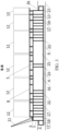
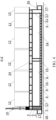
Fig. 2 - transverse section A-A forFig. 1 . -
Fig. 3 - longitudinal section B-B forFig. 1 . -
Fig. 4 - longitudinal section C-C forFig. 1 . -
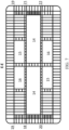
Fig. 5 - layout of the GBS main compartments. -
Fig. 6 - the GBS vertical walls arrangement in section D-D forFigure 2 . -
Fig. 7 - GBS vertical walls' arrangement in section E-E forFigure 2 . - The proposed GDCPSO offshore complex is a fully factory ready technical product that is a combination of process, engineering and auxiliary equipment for drilling, raw gas extraction, treatment, production, storage and offloading of LNG, WFLH and SGC.
- GDCPSO is fabricated at a dedicated yard and towed afloat to the place of installation.
- The GDCPSO is installed on
dedicated underbase foundation 9 on seabed 27 (Figs. 2 to 4 ) directly at the field, from which the feedstock is sourced, or at a distance from the field enabling hydrocarbon extraction operations, in accordance with the field development plan, where water depths exceed 14 m. To prevent scouring ofGBS underbase foundation 9 and seabed 27 around the GBS, gabions or other similar structures or berm backfilling may be arranged for seabed reinforcement. Once the field development is completed, the production complex can be deballasted and moved to operate in a different location. It can therefore be used for hydrocarbon production from shallow and medium-depth fields. - GDCPSO development will make possible development of fields located in shallow areas of the Arctic seas.
- The GDCPSO main components intended for hydrocarbon (raw gas) extraction, treatment and processing are the GBS and the topside - modularized drilling and process equipment (
Figs. 1 to 4 ). - The GBS is a three-dimensional reinforced-concrete structure serving as a support unit for the drilling facility, comprising
drilling rig 10,flare unit 11,topside process modules 12 andliving quarters module 13, and also functioning as a storage for respective products of processed raw gas, i. e. LNG, WFLH and SGC, consumables, chemicals, waste, and intended for installation onseabed 27 with the help of its own weight. -
Central part 1 of the GBS is a rectangular prism withtop slab 3.GBS protruding part 2 stretches along the sides of GBScentral part 1 all around its perimeter. GBScentral part 1 and protrudingpart 2share base slab 4, with protrudingpart 2 being lower in height thancentral part 1. - GBS
central part 1 includes main load-bearing structures -vertical walls 6 and horizontal slabs (top slab 3,base slab 4 and intermediate slab 5). The load-bearing structures support the required spatial rigidity of the GBS framework, for instance when the GDCPSO is transported and stays afloat prior to its installation.Vertical walls 6 made from reinforced concrete also separate the GBS into compartments in accordance with their intended use. -
GBS top slab 3 accommodates reinforced-concrete supports 7, on whichdrilling rig 10,flare unit 11,process modules 12, andliving quarters modules 13 are mounted. - Since
vertical walls 6 also serve as load-bearing structures that transfer the load from the topside to thebase slab 4 andunderbase foundation 9, reinforced-concrete supports 7 are erected above the intersections ofvertical walls 6 in GBScentral part 1. -
GBS top slab 3 slopes from the centerline towards the edges to evacuate atmospheric precipitation and process spills.Top slab 3 is designed to withstand explosion in case of emergencies. For cryogenic spill protection purposes,top slab 3 is reinforced with rebar made from very cold-resistant steel. - To distribute the load from the tanks that store LNG, one of the raw gas processing products, the design includes horizontal
intermediate slab 5 betweentop slab 3 andbase slab 4.Vertical walls 6 under this slab transfer the load tobase slab 4 and ensure the spatial rigidity of the structure. - Reinforced concrete based on modified normal density concrete with tensioned reinforcement is the main material of GBS
central part 1. -
Vertical walls 6 separate GBScentral part 1 into compartments (Fig. 5 to 7 ). Some (compartments 14, 15, 16) are used to store finished products; some (compartments 17 along the long sides of the GBS) are used for water or solid ballast.Compartments 18 formed by the short-end walls ofcentral part 1 on one side are used as borehole wells, at least onecompartment 19 is used to store consumables, at least onecompartment 20 is used to store chemicals, and at least onecompartment 21 is used to store waste, and also at least onecompartment 22 is used as an auxiliary compartment. GBScentral part 1 also houses engineering compartments 23. During transportation and operation, compartments 19-23 are also used as ballast compartments. During operation, consumables, chemicals and waste inrespective compartments -
Compartments 17 formed byvertical walls 6 ofGBS protruding part 2 are included in the ballast system. - The GDCPSO can stay afloat during transportation by sea to the installation site and can withstand ice impact in ice conditions. To settle the floating GDCPSO into a fixed position on the
underbase foundation 9 at the installation site, ballast compartments 17 are filled with sea water. - The GDCPSO external dimensions may vary depending on its production capacity.
- The main space-planning solutions of the GBS structures are defined by technological parameters, as well as internal and external loads affecting the GBS structure, taking into account their maximum possible negative combination.
-
Protruding part 2 of the GBS serves the following main purposes: - achieving the required target GBS buoyancy parameters;
- housing ballast compartments 17 primarily intended for the GBS balancing, ensuring the GBS being afloat with an even keel, without roll or trim;
- forming a natural protective barrier in case of design emergency collision / ship impact; protruding
part 2 will withstand and absorb most of the collision energy, preventing damage to the main volume of the GBS framework ensuring the integrity and preservation of main tanks and load-bearing structures of the topside; - housing auxiliary process and marine equipment ensuring tankers mooring and offloading of LNG, WFLH and SGC.
- LNG, WFLH and SGC storage tanks are installed in GBS compartments 14, 15, 16.
- GBS
central part 1 has a number of tanks (Fig. 5 ) that may have different design depending on the properties of substances to be stored. - Membrane tanks are used for LNG storage. In this case, the tank consisting of a metal membrane made of stainless steel or invar (Fe-Ni alloy) separated from the concrete structure by a thermal insulation layer is installed inside the concrete compartment. The insulation layer is located directly on
top slab 3,intermediate slab 5 and GBSvertical walls 6, transferring loads from the tank and its liquid content to the above-mentioned boundary structures. The GBS slabs and walls thus serve as support structures for membrane tanks, with which they are integrated into a single structural unit. To prevent any leaks, the bottom and the side surfaces of membrane tanks have a secondary barrier being an additional membrane installed inside the thermal insulation layer. - WFLH and SGC storage tanks are formed by GBS concrete compartments 15 and 16, with their boundary structures serving as a barrier.
- Smaller storage compartments 19, 20 and 21 as consumables, chemicals, and waste tanks (e. g. diesel, oil, mud, service water, glycol solution, drill cuttings, drilling wastewater, demineralized water, fresh water, etc.) are located along the GBS short ends.
-
Auxiliary compartments 22 andengineering compartments 23 in GBScentral part 1 are located on either side of main LNG, WFLH and SGC storage compartments 14, 15 and 16 and between them in the middle. These compartments are intended for process needs, equipment, service fluids, as well as access and evacuation routes for personnel. With dry compartments along the perimeter of main compartments for hydrocarbons storage, external surfaces of the boundary walls ofcompartments - The engineering equipment includes: a power supply system, including substations; a heating, ventilation and air conditioning (HVAC) system; a ballast water heating and recirculation system; a water supply and disposal system; firewater pumps and pipelines; foam fire-fighting system skids; an electrochemical corrosion protection system; telecommunication and alarm systems and a video surveillance system. The engineering equipment, for the most part, is located on the
top slab 3 and/or in/onprocess modules 12, with the remaining part being located in engineering compartments 23.Auxiliary compartments 22 can remain empty and accessible with the help of ladders and manholes. - Reinforced-
concrete supports 7 for the topside modules onGBS top slab 3 ensure that the support load be transferred fromdrilling rig 10,flare unit 11,process modules 12, andliving quarters module 13 to GBS main load-bearing structures. Structurally, supports 7 are reinforced-concrete pylons with heads for embedded components. - The locations of reinforced-
concrete supports 7 correspond to intersections of GBSvertical walls 6 enabling the distribution of loads from the topside modules. - Reinforced-
concrete supports 7 are designed to be high enough to provide enough space between GBStop slab 3 and a bottom ofdrilling rig 10,flare 11,process modules 12, andliving quarters module 13 as may be necessary to install piping andcabling 24 between the topside and the equipment in the GBS compartments as well as to ensure access for people and vehicles acrossGBS top slab 3. - The GBS ballast system comprises inner ballast compartments 17, including those under
intermediate slab 5, formed byvertical walls 6, as well as outer ballast compartments 17 in GBScentral part 1 andGBS protruding part 2, respectively. To prevent the water inballast compartments 17 from freezing, the design includes a ballast recirculation and heating system. The water in ballast compartments 17 is heated using waste heat from flue gas of gas turbines installed on the topside modules. - The ballast system performs two main functions:
- ballasting, i.e. changing the weight of GBS, ensuring required GBS draft when afloat and the structure stability once the GBS is installed on
underbase foundation 9; - GBS balancing, i.e. bringing GBS on an even keel, without roll and trim when afloat, through compensation with ballast water of deviation of the structure centre of gravity from its geometric center.
- The topside comprises the process equipment composed of
process modules 12. The number ofprocess modules 12 is decided upon during the production complex engineering phase. Location of the modules on the GBS is assumed taking into account their weight to make sure the centre of gravity of the GDCPSO is close to the geometric center of the GBS so as to reduce the volume of water ballast required to balance out the structure when afloat. -
Process modules 12 are three-dimensional steel frames with bracings, which accommodate process equipment, electrical equipment, automation systems, etc. - At a fundamental level,
process modules 12 are not different from topside modules used in the oil and gas sector at marine oil and gas structures of other types in terms of their design and layout. - The modules accommodate process installations for purification and treatment of raw gas, equipment of gas liquefaction, equipment for offloading of LNG, WFLH and SGC to tankers, as well as auxiliary equipment and utilities.
- The process systems for treatment and utilization of feedstock produced from wells are designed to work with formation fluid and produce gas, WFLH, and stable gas condensate. These systems are analogous to the systems usually used at onshore fields. The difference is that marine versions of the equipment are used.
- For ease of equipment maintenance and personnel access, each
process module 12 has several tiers (decks).Main tier 8 of eachprocess module 12 is at the same height to enable combining routes for evacuation and load movement across the topside, thus reducing the load onGBS top slab 3. Other tiers ofprocess modules 12 vary in height depending on their function and equipment. - The LNG, WFLH and
SGC offloading jetties 25 are structurally integrated with the GBS and the topside, and are located along both long sides of the GBS.Jetties 25 are equipped with mooring fenders, breakers and offloading platforms with loading arms as well as other marine and process equipment enabling offloading. Drawings showwater level 26 in the water area. - Compartments may be separated by transverse partitions, except for main LNG storage compartments 14. Openings may be made inside walls of
ballast compartments 17 for water to flow through, and passages for personnel and penetrations for cabling and piping are made inengineering compartments - The drilling facility is designed for operating conditions at offshore fields and have relevant climatic design. To ensure the works related to well drilling, the drilling facility comprise drilling rig 10 (
Fig. 1 ,4 ) with a handling device, blow-out preventing equipment, mud pumps, a mud circulating system, concreting facilities, pneumatic conveying system, a slurry preparation and injection system, a drilling wastewater collection system, hydraulic actuating gear for mechanisms ofdrilling rig 10, bulk materials depot, etc. -
Drilling rig 10 of the GDCPSO ensures all-year-round multiple well drilling and workover of vertical, directional, and horizontal wells. Multiple well drilling is ensured by movingdrilling rig 10 across the whole well pattern. -
Drilling rig 10 is installed on a short end of GBScentral part 1 with itsunderlying compartments 18 serving as borehole well. -
Drilling rig 10 includes a base frame with a substructure with outfitted with equipment and systems ensuring well drilling.Drilling rig 10 handling devices allow to position it above any point in the well pattern and to fixdrilling rig 10 in that position. The drilling is done throughtborehole wells 18 in the GBS (Fig. 4-7 ). - Process systems for well fluid treatment and disposal are designed to operate as part of an integrated GDCPSO.
- The design includes high-pressure and low-pressure flare systems for safe disposal of gases, including hydrocarbon gases/vapors, which are not consumed to produce power or heat, coming from high-pressure and low-pressure process equipment, respectively. The flare system is also engaged in emergencies and/or during blowdown. The gas coming from high-pressure and low-pressure systems is sent to flare
unit 11 to be burned at the flare tip (Fig. 1 ,3 ). - Living
quarters module 13 is used to provide accommodation (Fig. 1 ,3 ,4 ). Livingquarters module 13 is a safe, fully functional, fire-proof, reliably fixed building conforming to every applicable architectural, design, sanitary, and general technical requirement. Livingquarters module 13 is developed as a part of the topside in conjunction with other structures and systems. - Living
quarters module 13 is a fully functional modular structure containing living, public-use, sanitary, medical, and food premises as well as premises for auxiliary equipment to support the functionality of livingquarters module 13. - In conformity with safety requirements, living
quarters module 13 is installed as far away as possible from the most hazardous operating area, in whichdrilling facility 10 is located.
Claims (6)
- An offshore production complex for raw gas extraction, treatment and processing comprising a substructure with a topside located on it, the topside including a drilling facility, flare unit, process equipment for raw gas treatment and processing, and living quarters, with the substructure accommodating storage tanks for respective processed products, characterized in that the substructure is a gravity-based structure (GBS) that has a central part and a protruding part, with the central part being a rectangular prism with a top slab with the process equipment located on it, and the GBS protruding part stretching along the central part sides all along its perimeter and having vertical external walls, the central part and the protruding part sharing a base slab, the protruding part being lower in height than the central part, the GBS central part having longitudinal and transverse walls that form compartments, including ballast compartments and compartments accommodating storage tanks for respective processed products, and the GBS protruding part having internal walls that are perpendicular to its external walls and form ballast compartments.
- The complex according to claim 1 characterized in that the drilling facility includes a drilling rig installed on a short end of the GBS central part with its underlying compartments serving as borehole wells.
- The complex according to claim 1 characterized in that the GB S central part compartments formed by its short-end walls on one side, include at least one consumables compartment, at least one chemicals compartment, and at least one waste compartment.
- The complex according to claim 1 characterized in that some of the compartments in the GBS central part, including at least one of the compartments that is formed by its short-end walls on one side, are auxiliary compartments.
- The complex according to claim 1 characterized in that the GBS central part also has an intermediate horizontal slab storage tanks for respective processed products, i. e. liquefied natural gas, located on it, and there are longitudinal and transverse walls forming additional ballast compartments between the intermediate horizontal slab and the base slab.
- The complex according to claim 5 characterized in that some of the compartments in the GBS central part form storage tanks for other respective processed products, i. e. stable gas condensate and wide fraction of light hydrocarbons.
Applications Claiming Priority (2)
| Application Number | Priority Date | Filing Date | Title |
|---|---|---|---|
| RU2022116273A RU2779235C1 (en) | 2022-06-16 | Offshore production complex for the production, preparation and processing of raw gas for the production of liquefied natural gas, a wide fraction of light hydrocarbons and stable gas condensate based on gravity type (gtb) | |
| PCT/RU2022/000334 WO2023244134A1 (en) | 2022-06-16 | 2022-11-11 | Offshore production facility for producing, treating and refining raw gas |
Publications (3)
| Publication Number | Publication Date |
|---|---|
| EP4542000A1 true EP4542000A1 (en) | 2025-04-23 |
| EP4542000A8 EP4542000A8 (en) | 2025-11-19 |
| EP4542000A4 EP4542000A4 (en) | 2026-06-24 |
Family
ID=89191721
Family Applications (1)
| Application Number | Title | Priority Date | Filing Date |
|---|---|---|---|
| EP22947001.8A Pending EP4542000A4 (en) | 2022-06-16 | 2022-11-11 | OFFSHORE PRODUCTION PLANT FOR THE PRODUCTION, TREATMENT AND REFINATION OF RAW GAS |
Country Status (6)
| Country | Link |
|---|---|
| US (1) | US12662787B2 (en) |
| EP (1) | EP4542000A4 (en) |
| JP (1) | JP2025522262A (en) |
| CN (1) | CN119403993A (en) |
| CA (1) | CA3258835A1 (en) |
| WO (1) | WO2023244134A1 (en) |
Families Citing this family (1)
| Publication number | Priority date | Publication date | Assignee | Title |
|---|---|---|---|---|
| RU2767575C1 (en) * | 2021-11-24 | 2022-03-17 | Публичное акционерное общество "НОВАТЭК" | Integrated complex for production of liquefied natural gas (lng) on gravity-based foundation (gbf) |
Family Cites Families (17)
| Publication number | Priority date | Publication date | Assignee | Title |
|---|---|---|---|---|
| US3412564A (en) * | 1967-02-21 | 1968-11-26 | Pike Corp Of America | Sub-sea working and drilling apparatus |
| CA946629A (en) * | 1970-07-02 | 1974-05-07 | Gulf Oil Corporation | Portable products terminal |
| GB1366770A (en) * | 1972-04-04 | 1974-09-11 | Taylor Woodrow Const Ltd | Submersible structures |
| NO136375C (en) * | 1972-06-13 | 1977-08-24 | Selmer A S Ingeni R F | UNDERWATER FOUNDATION, INCLUDING A SUCCESSFUL CONCRETE CONSTRUCTION |
| JPS5421415A (en) * | 1977-07-19 | 1979-02-17 | Mitsubishi Heavy Ind Ltd | Barge for making iron reinforced concrete products |
| FR2410706A1 (en) * | 1977-12-05 | 1979-06-29 | Doris Dev Richesse Sous Marine | PLATFORM ALLOWING TO REACH A PRECISE POINT OF THE SEA BOTTOM OR A WATER BOTTOM |
| US4511288A (en) * | 1981-11-30 | 1985-04-16 | Global Marine Inc. | Modular island drilling system |
| US4497594A (en) * | 1982-09-30 | 1985-02-05 | Mcdermott Incorporated | Offshore structure and method of sinking same |
| US20040115006A1 (en) * | 2002-11-18 | 2004-06-17 | Gene Facey | System and method for converting a floating drilling rig to a bottom supported drilling rig |
| FR2894646B1 (en) * | 2005-12-14 | 2008-02-29 | Doris Engineering | TERMINAL FOR LIQUEFIED NATURAL GAS OR LIQUEFIED PETROLEUM GAS, AND METHOD FOR CONSTRUCTING SUCH TERMINAL |
| US8641327B2 (en) | 2007-07-30 | 2014-02-04 | Kellogg Brown & Root Llc | Methods and apparatus for protecting offshore structures |
| CA2981140C (en) * | 2014-11-27 | 2022-09-06 | Gravifloat As | Sea bed terminal for offshore activities |
| KR101778381B1 (en) | 2015-10-28 | 2017-09-13 | 현대중공업 주식회사 | FDLPSOU - Floating Drilling, LNG Production-Storage-Offloading Unit |
| NO20160906A1 (en) | 2016-05-26 | 2017-10-30 | Sembcorp Marine Integrated Yard Pte Ltd | Sea bed terminal for drilling |
| CN110803263A (en) | 2018-08-06 | 2020-02-18 | 吴植融 | Damping structure of straight cylinder type floating platform |
| US20220324541A1 (en) | 2019-11-28 | 2022-10-13 | Jgc Corporation | Structure for offshore plant |
| RU2762588C1 (en) | 2021-10-11 | 2021-12-21 | Публичное акционерное общество "НОВАТЭК" | Integrated production facility based on gravity type (gtb) |
-
2022
- 2022-11-11 EP EP22947001.8A patent/EP4542000A4/en active Pending
- 2022-11-11 CN CN202280097121.5A patent/CN119403993A/en active Pending
- 2022-11-11 CA CA3258835A patent/CA3258835A1/en active Pending
- 2022-11-11 US US18/866,213 patent/US12662787B2/en active Active
- 2022-11-11 WO PCT/RU2022/000334 patent/WO2023244134A1/en not_active Ceased
- 2022-11-11 JP JP2024564834A patent/JP2025522262A/en active Pending
Also Published As
| Publication number | Publication date |
|---|---|
| CA3258835A1 (en) | 2025-03-25 |
| EP4542000A4 (en) | 2026-06-24 |
| JP2025522262A (en) | 2025-07-15 |
| US20250320678A1 (en) | 2025-10-16 |
| WO2023244134A1 (en) | 2023-12-21 |
| US12662787B2 (en) | 2026-06-23 |
| EP4542000A8 (en) | 2025-11-19 |
| CN119403993A (en) | 2025-02-07 |
Similar Documents
| Publication | Publication Date | Title |
|---|---|---|
| US3766583A (en) | Offshore liquefied gas terminal | |
| US4188157A (en) | Marine structure | |
| US8684630B2 (en) | Underwater reinforced concrete silo for oil drilling and production applications | |
| US4202648A (en) | Floating plant for offshore liquefaction, temporary storage and loading of LNG | |
| CN107075824B (en) | Seabed terminal for offshore activities | |
| EP4417754A1 (en) | Integrated production complex on a gravity-based structure (gbs) | |
| US20250320678A1 (en) | Offshore production facility for producing, treating and refining raw gas | |
| EP4450378A1 (en) | Gravity-based structure (gbs) | |
| US3990254A (en) | Marine structure for offshore activities | |
| OA21850A (en) | Offshore Production Facility For Producing, Treating And Refining Raw Gas. | |
| RU2779235C1 (en) | Offshore production complex for the production, preparation and processing of raw gas for the production of liquefied natural gas, a wide fraction of light hydrocarbons and stable gas condensate based on gravity type (gtb) | |
| RU2312185C1 (en) | Marine complex for in-situ hydrocarbon fuel production of oil and gas condensate (variants) | |
| KR20180095015A (en) | Modular membrane LNG tank | |
| EP4438815A1 (en) | Integrated liquefied natural gas (lng) production facility on a gravity-based structure (gbs) | |
| Nezamian et al. | Concept evaluation of concrete floating liquefied natural gas (FLNG) | |
| OA21648A (en) | Integrated production complex on a gravity-based structure (GBS). | |
| OA21770A (en) | Integrated liquefied natural gas (LNG) production facility on a gravity-based structure (GBS). | |
| WO2005043034A1 (en) | Vaporizing systems for liquified natural gas storage and receiving structures | |
| OA21773A (en) | Gravity-based structure (GBS) | |
| WO2005045307A1 (en) | Liquefied natural gas storage structure having direct mooring for carriers | |
| RU163720U1 (en) | FLOATING STORAGE OF LIQUID NATURAL GAS OF GRAVITATIONAL TYPE | |
| WO2005045304A1 (en) | Liquefied natural gas storage structure having foundations extending into a bottom of a body of water | |
| GB2641937A (en) | Selective positioning of a pump tower in a storage tank for liquified natural gas | |
| Sédillot | The Hibernia gravity base structure |
Legal Events
| Date | Code | Title | Description |
|---|---|---|---|
| STAA | Information on the status of an ep patent application or granted ep patent |
Free format text: STATUS: THE INTERNATIONAL PUBLICATION HAS BEEN MADE |
|
| PUAI | Public reference made under article 153(3) epc to a published international application that has entered the european phase |
Free format text: ORIGINAL CODE: 0009012 |
|
| STAA | Information on the status of an ep patent application or granted ep patent |
Free format text: STATUS: REQUEST FOR EXAMINATION WAS MADE |
|
| 17P | Request for examination filed |
Effective date: 20241126 |
|
| AK | Designated contracting states |
Kind code of ref document: A1 Designated state(s): AL AT BE BG CH CY CZ DE DK EE ES FI FR GB GR HR HU IE IS IT LI LT LU LV MC ME MK MT NL NO PL PT RO RS SE SI SK SM TR |
|
| DAX | Request for extension of the european patent (deleted) | ||
| RAV | Requested validation state of the european patent: fee paid |
Extension state: KH Effective date: 20241126 Extension state: MA Effective date: 20241126 Extension state: TN Effective date: 20241126 |
|
| RBV | Designated contracting states (corrected) |
Designated state(s): AL CH GB IS LI MC ME MK NO RS SM TR |
|
| REG | Reference to a national code |
Ref country code: DE Ref legal event code: R108 |
|
| REG | Reference to a national code |
Ref country code: DE Ref legal event code: R079 Free format text: PREVIOUS MAIN CLASS: E21B0043010000 Ipc: E02B0017020000 |
|
| A4 | Supplementary search report drawn up and despatched |
Effective date: 20260522 |
|
| RIC1 | Information provided on ipc code assigned before grant |
Ipc: E02B 17/02 20060101AFI20260518BHEP Ipc: E21B 43/01 20060101ALI20260518BHEP Ipc: B63B 35/44 20060101ALI20260518BHEP Ipc: E02B 17/00 20060101ALI20260518BHEP |